1
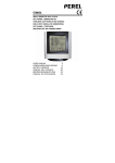
REMOTE MAINCLOCK 2 PTC-240B OPERATING ELEMENTS bedienelemente 1. Control Key Pressing these keys help to move through the displaymenu. 1. Funktionstasten Durch Drücken dieser Tasten bewegen Sie sich durch das Display-Menü. 2. Display The display shows the functions of the clock and the programmed events. 2. Anzeige Das Display zeigt die Funktionen der Uhr und Ihrer einprogrammierten Ereignisse. 5 4 3 3. BUS-connector Here the Main clock is connected to the ProLine BUS. 3. Bus-Anschluss Hier wird die Hauptuhr mit dem ProLine-Bus verbunden. 4. Update-connector Here the firmware program adapter PPA-001 is connected. 4. Update-Anschluss Hier wird der Firmware-Programm-Adapter PPA-001 angeschlossen. 5. Build-in slots Here the different relay cards are to be put into the device such as PTC-008x or PTC-108x 5. Einbauschächte Hier können Relais-Karten des Typs PTC-008x oder PTC-108x eingebaut werden. INITIAL OPERATION inbetriebnahme The basic device is delivered without modules and relay cards. In order to insert the different types of relay cards, the actual cabinet has to be opened. The exact way of doing such is described in the according module section of this manual. Das Grundgerät wird ohne Module oder Relaiskarten geliefert. Zum Einbau von verschiedenen Arten von Relaiskarten muss das Gehäuse geöffnet werden. Die genaue Vorgehensweise wird im Kapitel der jeweiligen Module beschrieben. A Cat7-S/STP cable should be used as a BUS cable. A Cat5S/STP cable with an overall screen is also possible. In case of large BUS lengths a separate supply line with 2 x 0, 8 mm or thicker is a better choice for the operating voltage. In order to avoid a drop in voltage on the cable, the remote microphones may also be connected directly to the socket with 24 V. The pair of wires of the RS-485 port has to be equipped with a 120 Ohm-load resistor; otherwise malfunction may occur due to reflection of the cable head. All devices connected to the BUS are to be regarded as equal and therefore can be wired in random order. The PSS-224 B may also be located in the center of the remote microphones. Star-shaped wiring is not possible. 4 Als Buskabel sollte ein Cat7-S/STP-Kabel verwendet werden. Möglich ist auch ein Cat5-S/STP-Kabel mit Gesamtschirm. Bei sehr großen Buslängen ist eine separate Versorgungsleitung mit 2 x 0,8 mm oder stärker für die Betriebsspannung eine bessere Wahl. Um Spannungsabfälle auf dem Kabel zu vermeiden. Das Adernpaar der RS-485-Schnittstelle muss an beiden Enden mit je einem 120-Ohm-Abschlusswiderstand versehen werden, sonst kommt es unweigerlich zu Fehlfunktionen aufgrund von Reflektionen an den Kabelenden. Alle am Bus angeschlossenen Geräte sind als gleichwertig zu betrachten und können daher in beliebiger Reihenfolge verdrahtet werden. Die PTC-240x kann also auch in der Mitte zwischen den Sprechstellen liegen. Eine sternförmige Verdrahtung ist nicht möglich.