1
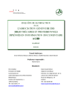
User’s Manual
W-Ie–Ne-R
VME 430 Cern Spec.
Plein & Baus GmbH
General Remarks
The only purpose of this manual is a description of the product. It must not be
interpreted as a declaration of conformity for this product including the product and
software.
W-Ie-Ne-R revises this product and manual without notice. Differences between the
description in manual and the product are possible.
W-Ie-Ne-R excludes completely any liability for loss of profits, loss of business, loss of
use or data, interrupt of business, or for indirect, special incidental, or consequential
damages of any kind, even if W-Ie-Ne-R has been advises of the possibility of such
damages arising from any defect or error in this manual or product.
Any use of the product which may influence health of human beings requires the
express written permission of W-Ie-Ne-R.
Products mentioned in this manual are mentioned for identification purposes only.
Product names appearing in this manual may or may not be registered trademarks or
copyrights of their respective companies.
No part of this product, including the product and the software may be reproduced,
transmitted, transcribed, stored in a retrieval system, or translated into any language in
any form by any means without the express written permission of W-Ie-Ne-R.
PROFIBUS if named in this document is replaced by CANbus
Mains Voltage and Connection
The Power supplies are equipped with a “World”- mains input, which works properly
form 94VAC up to 264VAC and within a frequency range of 47 to 63Hz.
Before connecting to the mains please double-check correspondence.
The mains input connection at the power supply side is done with a 3-pin Hirschmann
connector (input current max. 16 A) or power terminals.
Hirschmann
Pin No.
Signal
Description
Color of the Wire
Pin 1
L
Phase
black or brown
Pin 2
N
Return, Neutral
blue
Pin 3
Earth
not connected
PE
Protective Earth
green/yellow
Safety
After connecting the Power box to the mains, the mains input module is powered
permanently. Filter and storage capacitors of the power factor correction module are
charged with about 400VDC. The DC-On-Signal as well as a power switch at control
board (if any installed) operates as a DC on/off switch only and not as a mains breaker.
Therefore it becomes dangerous if the box cover is open. In this case a lot of
components on high voltage potential get touchable!
Before starting any kind of work inside the power box remove the unit from mains
and wait a couple of minutes with your activities! Discharge the primary DC Filtercapacitors by use of a well isolated 22 ohm 10W resistor.
September 08
Every fan is single controlled by the micro-processor based fan failure and fan
speed control mit. Thus a malfunction of any one of the fans is detected. With
the FAN SPEED switch the speed of the fans can be step wise reduce or increase
. Further, it is possible to switch the fans complete off if the optional crate
temperature measurement (at slot 1 position) is installed. In this case the bin
temperature is automatically controlled. If the bin temperature reaches the
threshold value of 45°C the fans are automatically switched On.
For monitoring of fan speed, voltages, currents, temperatures, and optional bin
temperature and network address the control and monitoring unit is equipped
with a LED - alphanumeric display. In the case of illegal conditions or crate
failures it serves as diagnostic system.
For the data transfer between fan-tray, bin and power supply based on the
RS232 standard (2400 Baud) the free lines 41 and 42 a t PG46PG47 (see wiring
scheme) are used. They now correspond to the RS232 TXD and RXD lines.
Further, the free lines 8 and 9 a t PG46PG47 are used for the optional bin
temperature measurement (at slot 1)and for the SYSFAIL signal respectively.
By this way the monitoring and controlling operations are extended by a lot of
important functions.
By use of an optional possible interface all fan parameters can be monitored
and each fan can be single controlled. If using all W-le-Ne-R power supply, fantray and bin, a lot of control functions concerning the power supply are possible
too.
Optionally several interfaces are available as CAENET, IEC, and PROFIBUS.
Thus, remote control from a single point by an IBM-PC or a seperated VME or
CAlMAC crate is possible by use of
I E C interface
CAENET interface
PROFIBUS interface
for up to 15 crates
for up to 99 crates
for up to 256 crates.
According to the CERN V-430 specification for remote control and monitoring
the following signal lines are available a t a monitoring and control connector
(CANON Type DAC 15-S-FO)which is placed at the bin backside,
WWQ
mudfx,ring
~
and oan%ral
Description
line
STATUS
FAN FAILURE
A.C.POWER INHIBIT
SYSRESET
OV SIGNAL
DISABLE
GND
status monitor output
fan failure output
remote on 1off
manual system reset
common control return line
global trip-off disable input
ground.
STATUS and FAN FAILURE are switched by relais contacts. They are close
connected to the return lines in case of correct operation. The system reset
circuit is activated by a short circuit between the SYSRESET and the GND
signal line. For trouble shooting purposes the global trip-off can be disabled by a
jumper connection between INHIBIT and OV SIGNAL lines.
I
1.3. VME-fan-tray UEL 4251EC
The UEL 425/EC is the W-Ie-Ne-R economic fan tray unit version which
conforms the CERN V430 standard. The unit is equipped with 3 axial 2-speed
AC-fans. The fans are noise decreased mounted with shafts on ball bearings.
SWITCHES
main switch for ventilation and power
protected located switch for SYSRESET
circuit activation
P
SYS RES
F
RANGE SEltECT
1
FAN SPEED
circular selection switch to choose
voltage range
2 position button for fan speed
FAN AUTO OFF
1
switch to choose between local and
remote warning or d.c. voltage cut-off
after fan-failure
LED - INDICATORS
green large LED lights if PO WER is on
green LED lights if all voltages are
within the limit
yellow LED lights if a fan failure is
recognised
yellow LED lights if an overheat in the
power supply occur
SYSFAIL
~
.J
red LED lights if VME-bus system
generates the SYSFAZL signal (system
red control LED for reduced fan speed
(approx. 50%)
for 'only warning after
; . , ~ ~ ~op+~,::?zz~
$ ~ u ~ ~ ; (red
- control
~failure'LED
fan
mode (d.c. off after fan
.... . . . .
..............
...........
...:
.:.
.....:......:.:....
................
failure disabled)
Sys Res Switch
Auto Off Switch and LED
Fan Speed Switch and LED
-
Range select Switch
Voltage display
Current Display
LED's for Status, Fan Fail
Overheat and Sys Fail
Power LED
Power switch
Fig.2 UEL 425 EC fan tray front panel
User's Manual
VME 430 Cern Spec.
W-le-Ne-R
Plein 8 Baus GmbH
As the microprocessor controlled fan tray unit the UEL425lEC can operate in
two different modes. In the standard mode the air is taken from the front and
then pushed upwards to the modules. A bottom side air inlet for full cooling
efficiency can be reached by removing the bottom plate of the fan-tray and
mounting an optional front Cover. The maximum air flow reached is greater
then 380 m3/h and shows a good homogeneity. Working with front air inlet only
a reduced air flow is available. The static pressure is equal to 8 mm water
column. With the 2 position FAN SPEED switch the speed of the fans can be
reduced.
For monitoring of voltages and currents the control and monitoring unit is
equipped with a dual digital panel meter. The voltage range can be chosen by a
circular selection switch.
Al1 elements of the control unit are placed at the front panel of the fan-tray,
1.3. VME-power-supplyUEP 429
The VME-power-supply UEP 429 is a micro-processor controlled switching
power supply designed in a high density modular technology. The power supply
is placed within the bin in the upper part of the back behind the backplane. It
can be removed or inserted easily by the User.
The a.c. input voltage is 180-264 V 147-63 Hz whereby the input is protected by
a slow-blow fuse 10N250V. A solid state relay comects the power supply to a.c.
mains. The relay is activated by the POWER ONIOFF switch mounted at the
fan-tray front panel.
The VDE 0871 class B rule concerning RFI rejections is accomplished. The
insulation performs the CERN V430 specification with input to output 1KV-eff.
However, due to the bin - fan-tray and bin - power supply connectors (48 pinRADIALL) required by the CERN V430 specification the ISO NDE norm is not
realised.
The available voltages with the corresponding maximum available currents are
given in the following table
[ tem
0370- 0302. H
0370- 0012. H
0370- 0312. H
0370- 0052. H
0370- 0353. H
0371- 0352. H
September 08
-
-
Power cupplies VME- Series 430
UEP 429 CERN 5V1100A +/-I 2Vll OA
UEP 429
5V1200A +/-I 2Vll OA
UEP 429
5V1300A +I-12Vll OA
UEP 429
5V1100A -5,2V1100A -2Vl50(1OO)A +/-I 2V10A
UEP 429
5V1200A -5,2V1100A -2V150(1OO)A +/-I 2Vll OA
UEP 429
5V1100A -5,2V1100A -2V150(1OO)A +/-I 2Vll OA +/-I 5Vll OA
90-265VAC
90-265VAC
90-265VAC
90-265VAC
90-265VAC
90-265VAC
The power output to backplane connections conform to the CEFtN V430
specification, i.e. the high current d.c. power outputs (+5V, -5.2V7-2V and GND)
are connected with the backplane bus bar via massive special fork connectors
and the low current outputs (+I-12V, +I-15V) as well as the sense, monitoring
and control signal lines via a multiway (48-pin RADIALL) connector. Each
output rail can be adjusted by a multi-turn potentiometer which is placed a t
each power module covered by the top plate, but free accessible.
The voltage regulation parameters depends on the module type, i.e. switched or
linear regulated module. The static regulation is better than 0.2% or 0.3% for +I100% load change combined with +/_15%mains variation for the switched and
the linear regulated modules, respectively. In the case of dynamic regulation the
deviation is lower than 0.7% within 0.35 ms for +I-25% load change for the
switched module and lower than 0.7% within 0.2 ms for +/_25%load change for
the linear regulated one. The periodic and random deviations (PARD) are less
than 20 mV(pp) for 20 MHz and 5 mV(pp) for 2 MHz band width, as well as 5
mV(pp) for 20 MHz and 1 mV(pp) for 2 MHz band width for the linear regulated
voltage. If the UEP 429 is used in a compatible bin the PARD may be higher but
within the CEFtN-specification (<50mV(pp))
By the help of the remote sense lines an output voltage compensation of a t least
0.5 V is possible. An internal 10 ohm resistor is mounted between each sense
and power line to avoid a going out of control in the case of external
discomected sense lines.
Turning on the power supply all voltages reach the nominal values nearly
simultaneously within 50+/_2.5ms (start-end-time) whereby the voltage versus
time curve shows a monotone behaviour. The start-off-time which corresponds to
a value of 10% of the nominal voltages is reached after 2.5+/_2.5ms. The turnon inrush current is limited by a soft start-circuit to a maximum value of 12 A.
The UEP 429 shows a n excellent long time stability. Under constant conditions
the maximum voltage drift is lower than 10 mV or 0.1% within 24 hours or 50
mV or 1.0% within 6 months. The temperature coefficient of the output voltages
is less than 2.0*10-4 /K.
To dissipate the heat produced within the power packs two fans are placed in
the bottom of the power supply.
Al1 monitoring and control operations are performed by a micro-processor based
alarm and control circuit which is placed inside the UEP 429. To protect both
the power supply and the VME modules, a d.c. cut-off is started in the case of,
- overheat in the power modules (each module is
equipped with temperature sensors);
- overload, i.e. 115% of nominal maximal current is
exceeded (trip-off current set to 115% as
standard value, can be changed [see 2.2.1);
- overvoltage, if voltage >125% (hardware) and if
>105% (software, can be changed)
- undervoltage, if voltage <97.5% (software, can be changed)
- f a n failure.
If the d.c. cut-off is started all voltages decrease within a time of 5 ms to a
minimum of about 20% of their nominal values (or -lV for the -2V output).
For monitoring all voltages and currents as well as the temperature inside the
power supply (and fan speed, air entry temperature, and optional parameters,
See 1.2) can be shown on the alphanumeric display of the fan-tray. The current
information is given by a d.c. output reference voltage which corresponds to the
current with a ratio of 1V1100A (+5V, -5.2V, -2V) or 1VIlOA (+I-12V, +/,15V).
The display ADC resolution is 10 bit. The accuracy of the voltage measurement
is better than 0.5%. The accuracy of the current measurement depends on the
corresponding voltage, i.e. for +/_5Vit is better than 2A in the range between 5A
- 50A and for -2V it is better than 1A in the range between 1A - 20A. Above
these current ranges the accuracy is at least 5% of the final value. In the case of
+I-12V and +I-15V the accuracy is better than 0.2 in the whole current range.
In addition to the standard VME and CERN V430 specification it is possible to
change and adjust the values for current limits (trip off current) as well as for
minimum and maximum voltages (see 2.2). Thus, module damages during tests
can be preyented. However, this software based feature works only if using
together W-le-Ne-R power supply, fan-tray, and bin.
For the data transfer between fan-tray, bin and power supply based on the
RS232 standard (2400 Baud) the free lines 41 and 42 at PG44 - PG45 (see
wiring scheme) are used. They now correspond to the RS232 TXD and RXD
lines. By this way the monitoring and controlling operations of the power supply
are extended by a lot of important functions.
Optional several interfaces for the fan-tray are available as CAENET, IEC,
and PROFIBUS. Thus, remote control and operation of the fan-tray and the
power supply is possible from a single point (IBM-PC or a separated VME or
CAMAC crate, See 1.2.).
User's Manual
VME 430 Cern Spec.
W-le-Ne-R
Plein & Baus GmbH
1.5. Technical data Summary
BIN UEV 431
Dimension
Backplane
Weight
483 mm X 8U X 420 mm (whd)
21 slots for 6U VME-system cards
multilayer monolith, J l , J 2 , and
Ja, (CERN V430)
9.6 Kg
FAN-Tray UEL 425
Number of fans
Fan type
Fan live time
Maximum air flow
Max. static pressure
Control unit
Weight
3
SANYO DC San Ace 109P1224H102
60.000 h (at 40 OC)
~ 5 4 m3
0 /h (bottom air inlet)
>400 m3 /h (front air inlet)
>10mm water column.
micro-processor based with
alphanumeric display (10 bit ADC)
3.3 Kg
FAN-Tray UEL 425 EC
Number of fans
Fan type
Maximum air flow
Max. static pressure
Control unit
Weight
September 08
3
Papst 4658N
>380 m3 /h (bottom air inlet)
>8mm water column.
dual digital voltage 1 current panel meter
3.9 Kg
11
User's Manual
W-le-Ne-R
VME 430 Cern Spec.
Plein 8 Baus GmbH
I.5 Technical Details of UEP429 Power Supplies
Mains input
Sinusoidal: CE EN 61000, pow. fact. 0,98 (230VAC), 92 ...264VAC, 16A
Inrush current:
limited to nominal input current, max.
Available modules
min. to max.
2... 7V
6... 16V (+I-)
Type MEH
Type MDH
range
max. output
100A +15% /
20A +15% I
550W
300W (600W)
Regulation
(+/-100% load, +/- f~illinains
static: MEH 550W1650W
range)
MDH
dyil.: MEH. MDH
<0,05%
<1 OOinV
Recovery time +/-25% load:
NIEH / MDH
within +-1% within +-0,1%
0,2ms
0,5ms,
Sense compensation range:
difference between min. and max. output voltage
Noise and ripple
<1 OmVpp, (0-20MHz )
:
<15mV
(+I-100% load, +/- full mains range)
(+/-25% load)
<2mVrms (0-30MHz)
Operation temperature range:
Temp.-coefficient :
Stability (conditions const.):
0....50°C without derating, Storage:-30°C ... +85"C
< 0,2% / 1CIK
lOmV or 0,1% I 24 hours, 25mV or 0,396 / 6 month
Current limits:
Voltage rise cliaracteristics:
adjustable to any lower level
monotonic 50n1s, processor controlled.
Protective equipment
Overvoltage crow bar :
DC Off (trip off):
trip off adjusted to 125% of nominal voltage each output
within 5nls if >2% deviation from adjusted nominal values,
by reason of overload, overheat, over-voltage,
under-voltage, (bad status) and fan fail
if temperatures exceed 1 10°C heat sink, 70°C ambient
Trip off points adjustable, processor controlled. Output capacitors will be discharged by the crow
bars if the power supply trips or when switched off.
Efficiency :
75% ... 85%, depends on modules / output voltage
Life time:
DC- Fans:
Power Supply electroilics:
25°C ambient >85 00011
40°C >I30 000 h
Weight:
14....18kg dependent upon number of fitted modules
September 08
40°C >65 000 h
2. Oneratin~instructions
2.1. global operations
POWER ONIOFF
switch up :
switch down :
on (green POWER LED lights)
off
SYSRESET
pushing will call a VME-SYSRES, after
pushing the display shows 'SYS RES'
MODE SELECT
switch up :
switch down :
next mode (UEL 425)
previous mode (UEL 425)
7 position switch for voltage range (UEL 425 EC)
The red SYS FAIL LED lights up if the SYSFAIL signal is generated by the
VME-bus system. This indicator works only if using all together W-le-Ne-R
power supply, fan-tray, and bin.
On the alphanumeric display in the centre of the fan-tray front panel the values
of fan speed, temperatures, voltages and currents as well as the adjusted
voltage and current limits will be shown. To choose between the available modes
push the MODE SELECT switch.
The following table gives a look about all available modes and shows examples
for the displayed values. Note that the modes marked by * only will be shown if
the optional available network interface (CAENET, IEC. PROFIBUS) and 1 or
the bin temperature measurement a t slot 1is installed.
...................
........................................................................................................................................
................................................................................................................................................
...............
.... . . . . . . . . . ......
:;. ....: ::~ijjjjijj,ijjjjj:j~~:;:),:
,,::ii::;,,:j::::::jjj:i:ji:jj:;:j;;::~::,~jljl:::I:iI:IIII;.~$~ijj~;~~~~ji~:.I,
.
....
....
........
...............................................................
.......................................................................
:i::&vai$hb~e:ijM&&@iiand
Mode Voltage
+5V
5.00
+12V 12.00
+15V 12.00
STBY 5.00
-5V
5.20
-12V
12.00
-15V
15.00
-2V
2.00
FANS 3000
TEMP
25
PTMP 55
BTMP:
35
CAEN*
ADDR
PROF
ADDR
IEC* ADDR
Ej&&piw
Current
100.0
Description
+5V channel
+12V channel
+15V channel
---stand-by channel
80.00
-5.2V channel
6.00
-12V channel
3.00
-15V channel
40.00
-2V channel
RPM
fan rotation speed
"C
fan air inlet temp.
OC
power supply temp. *
OC
bin slot 1temp.
12
CEANnet addresg*
12
Profibus gddress
12
IECbus address
6.00
3.00
.'
2.2. Fan-tray operations
FAN SPEED
switch up :
switch down :
AUTO OFF
switch up :
switch down :
step wise increase of fan
speed
step wise decrease of fan
speed
auto off enabled, a fan failure will set off the crate
auto off disabled, a fan
failure will not set off the
crate, only local and remote
waniing is given
The maximum value of fan speed is up to 3120 rpm. If the speed is lower than
3000 rpm the red SLOW SPEED LED lights. Change of fan speed is possible
independently from the displayed mode. If another range of the display was set
before pushing the FAN SPEED switch the display shows the speed for 5 sec.
and returns back to the previous range. The display shows the nominal speed of
the blowers and twinkles if it differs from the given real speed.
The yellow FAN FMLURE LED lights in the case of any fan-failure.
Power-supplymonitoring and control operations
All present voltage and current values of the several voltage output lines as well
as the temperature inside the power supply can be shown on the alphanumeric
display of the fan-tray. To select between the display modes push the MODE
SELECT switch as given in 2.2.
Using both W-le-Ne-R power supply and fan-tray it is also possible to adjust
the controlling limits of the power supply. The values of the minimum and
maximum output voltage and the maximum current which cause a cut-off can
be changed according to the following instructions,
1.
Switch on fan-tray and select channel (e.g.+12V) with MODE
SELECT switch.
2.
Switch up both POWER and MODE SELECT switches together for
about 5 sec. Then the controlling mode menu including selected
channel, limit (starting with IOFF), and the corresponding value will
be shown on the display.
3.
Choose the type of limit (trip-off current: IOFF, minimum voltage:
UMIN, and maximum voltage: UMAX) by pushing the MODE
SELECT switch
4.
Switch up POWER until the value twinkles.
5.
Change the value by pushing the MODE SELECT switch down
(value will decrease) or up (value will increase).
6.
To accept the new value switch down POWER. The power supply
control unit is programmed indicated by flashing PROG. To
change the other limits repeat step 3 - 6.
7.
Switch POWER down to end programming.
Note that all control limits are stored within the power supply control unit
which is located inside the power supply. During programming all remote
control signals will be ignored.
2.4. Error message list
Both, w - i e - ~ e - r tpower supplies and fan-trays are equipped with microprocessor based monitoring and control units. Thus, any fan or power module
failure will be detected and on the alphanumeric display an error message is
shown. This is a usefd information for trouble shooting.
2.4.1 Error messages during self test after switching on
Fan-Trav failures
CHKS CONF
Configuration check sum error
CHKS UCAL
Check sum error of calibration voltage
CHKS ZCAL
Check sum error of calibration current
PROM CONN
internal CPU error
CHKS ADDR
Check sum error of network address
C H m STAT
Check sum error of previous mains onloff
status
CHKS FAN
Fan-tray check sum error
Power supplv failures
P S PROM CHKS
Power supply check sum error
Pushing SYSRES the first three error messages will be ignored, but keep in
mind the defective conditions especially, for the voltage and current monitoring.
The other errors, instead of the CPU error are automatically corrected so that
the error message serves only as information for the User.
2.4.2 Run time error messages
FAN OFF
Fan failure
TEMP OFF
Temperature of power supply too high
AC FAIL
Failure of a.c. power (line)
+/_??VOV
Overvoltage of channel +/_??V
+/-??V W
Undervoltage of channel +/-??V
+/-??V OC
Overcurrent of channel +/_??V
2.5. Change of air flow direction
The UEL 425 fan-tray can operate in two different modes. The standard fan
takes the air from the front and pushes it upwards to the modules. To reach full
cooling efficiency through a bottom side air inlet remove the bottom plate and
change the front cover plate according to the following instructions:
1.
Release all screws of the fan-tray bottom plate and remove it.
2.
Release the screws fixing the front plate of the fan-tray and remove
front grid placed behind the front plate
3.
Insert front cover plate (optional) and fix all screws.
3. Test sheef!
A.1. Scheme of crate dimensions
A.2. Principe diagram
A.3. Wiring diagram
A.4. J l , J 2 , J„
pin allocation table and position scheme
B. Summaw data sheet
U
m
m
m
2 g,
2
0
E
W
L
C
z'
U
=
L
Lm
0
a
Cr
N
V
W
W
L
::
C-i
,2
-
X
0
I
L
L
I
D
F-
L
Tc
W
'J
n3
Ci3 L
L
0
a
TI
\T cn
-
L
P
-
W
3
0
n3
Ir-
Ir
--
g-
E C
-
>
a
N
I
L j
a.
a.
r-
C
m
a
Y
lndur s u r e ~
U
m
m
Ln
3
m
,
noU
d L m m
oom-
W
L U W L
--
>
I
UriUW
CCOU
OOLC
U E ari
hCt
P
-
m
m
-p
>
L n
4)OjUO
+
L
~OU6JlIOJ7UO~
U
6
>
0
m
N
---7
U
Y
C m
m C L W
r i o U
4 L m m
o o u 1 L
U
W
Y-
UOUIK
n
C
o
m
m
w
L
L
U
C
Y
L
z
m m
L c
+ m
I
m U
L
L
a
O
L.
O
~
6
oxtl
0x1
1
IOJJUQ3
--
PlIJl
Pin Nwnbcr
Row B
Row A
Row C
Pin Niimbcr
Row A
1
Row i3
Row C
W8
D@
D10
D11
D12
D13
D14
D15
2
3
4
5
6
7
8
U x r Dciincd
U x r Dciined
Uscr Dciincd
Uscr Dciincd
Uscr Dciincd
Uscr Dciincd
Uscr Dciincd
Uscr Dcfincd
+5 VDC
GND
(I) RESEKVED
A24
A25
A26
A27
A2S
Uscr Dciined
U x r Dciincd
Uscr Dcfincd
Uscr Dcfincd
Uscr Dciincd
Uscr Dciincd
Uscr Dcfincd
User Dcfincd
BG20UT*
BG31N'
BG30UT'
BRO*
BRl*
BR?*
BR3'
AM0
GND
SYSFAL*
BERR*
SYSRESET*
LWORD*
AM5
A23
A22
9
10
11
12
13
14
15
16
Uscr k f i n c d
Uscr Dciincd
Uscr DcGncd
Uscr Dcfined
Uxr Dciin~i
Uscr Dciincd
Uscr Dcfincd
Uscr Dciincd
A29
A30
A31
GND
+5 VDC
D16
D17
D18
U x r Dcfincd
User Dcfincd
Uscr Dcfined
Uccr Defincd
Uscr Dcfincd
Uscr Dcfincd
Uscr Drfinul
Uscr Dcfirilil
GND
AS*
GND
IACK*
IACKIN*
IACKOUT*
AM4
A07
AMI
AM2
AM3
GND
( t t ) SERCLK
(tt)SERDAT*
GND
IRQ7 *
A21
AZO
Al9
Al8
Al7
Al6
Al5
AI4
17
18
19
20
21
22
23
24
(Jscr Dcfiricd
Uscr Dciincd
Uscr Dciincd
User Dciincd
Uscr Dcfincd
Uscr Dciincd
User Dciincd
Uscr Dcfincd
D19
D20
D2 1
D22
D23
GND
D24
D25
Uscr h i i r i c d
U.xr Dcfiiicd
Uscr Dcfincd
Uccr Dcfincd
Uscr Dcfined
User Dciincd
U x r Dciincd
Uscr Dcfiiicd
AM
A05
AM
A03
A02
A01
-12 VDC
+5 VDC
IR@*
RQS*
Al3
Al2
Al 1
Al0
A09
A08
+I2 VDC
+5 VDC
25
26
27
28
29
30
31
32
Uscr Dciincd
Uscr Dcfincd
Uscr D c i i n d
User Dcfincd
Uscr Dcfincd
Uscr k f i n c d
User Dciincd
Uscr Dcfincd
D26
D27
D28
D29
D30
D3 1
GND
+5 VDC
User Dcfincd
IJscr Dcfincd
U.xr Dcfincd
U.xr D c f i n d
Uscr Dcfincd
Uscr Dcfinui
Uxr kfincd
Uscr Dcfincd
1
2
3
4
5
6
7
8
D00
D01
Da2
W3
DO-2
D05
D06
D07
BBSY*
BCLR*
ACFAL*
BGOIN*
BGWW*
BGIIN*
BG I O U T
BG2IN'
9
10
11
12
13
14
15
16
GND
SYSC1.K
GND
DSI*
DSO*
WKITE*
GND
DTACK*
17
18
1Y
20
21
22
23
24
25
26
27
28
29
30
31
32
mw*
IRQ3'
IRQ2'
IRQI*
+5VSTDBY
+ 5VDC
'
Nuics: ( t j RESERVED was n d c f i n c d a s REi'RY*, and (tt) SERCLK SERDAT*
wcrc ch:mgcd io iiscr dcfincd pins in ~ h Kcvision
c
D VhlEbus spwificaiioii.
Jaux
Pin Number
1
2
3
4
5
6
7
8
Row A
SN1
SN3
SN5
CK*
SG*
CL*
-2v
-15V
Row B
GND
GND
GND
GND
GND
GND
- 2v
CE
A.4. J l , J 2 , Ja- pin allocation table
Row C
SN2
SN4
GND
CK
SG
CL
-2v
+15V