1
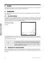
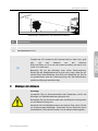
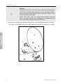
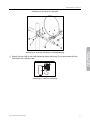
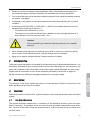
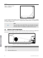
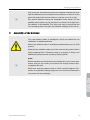
Mobile Sat-Anlage / Mobile Sat System Aufbau und Montage / Installation And Assembly Version: 12.03.2013 - Deutsch / English Vorwort Vorwort Herzlichen Glückwunsch zum Kauf einer mobilen Sat-Anlage von smart. Lesen Sie die Aufbau- und Montageanleitung vor Inbetriebnahme gründlich durch. Alle Arbeiten sollten sorgfältig erfolgen. Beachten Sie insbesondere die Sicherheitshinweise. Ihre smart electronic GmbH Industriestraße 29 78112 St. Georgen Germany Service-Hotline: +49 (0) 7724 9478-555 Telefax: +49 (0) 7724 9478-333 E-Mail: [email protected] Internet: www.smart-electronic.de © smart electronic GmbH 2013 Alle Rechte, technische Änderungen, Irrtümer sowie Druckfehler vorbehalten. Nachdruck, Vervielfältigung oder Übersetzung, auch auszugsweise, ist ohne schriftliche Genehmigung von smart nicht gestattet. 2 smart Mobile Sat-Anlage Sicherheitshinweise Inhaltsverzeichnis 1 Sicherheitshinweise ....................................................................................................... 4 2 Bestimmungsgemäße Verwendung .............................................................................. 5 3 Garantie ........................................................................................................................... 6 4 Standortwahl ................................................................................................................... 6 4.1 Die richtige Richtung ........................................................................................ 6 4.2 Hindernisse in der Empfangsrichtung .............................................................. 6 5 Montage der Antenne..................................................................................................... 7 6 Lieferumfang ................................................................................................................. 10 7 Befestigung der Antenne ............................................................................................. 11 8 Montage des F-Steckers.............................................................................................. 12 9 Anschluss der Geräte ................................................................................................... 14 10 Ausrichten der Satellitenantenne ................................................................................ 15 11 Einstellwinkel der Satellitenantenne........................................................................... 18 smart Mobile Sat-Anlage 3 Sicherheitshinweise 1 Sicherheitshinweise Achtung! Lesen Sie die Sicherheitshinweise sorgfältig durch, bevor Sie die Anlage montieren und in Betrieb nehmen. Beachten Sie alle Warnungen und Hinweise auf den Produkten und in dieser Bedienungsanleitung. Die Warnhinweise erheben keinen Anspruch auf Vollständigkeit. Im Zweifelsfall ist ein Fachmann zu Rate zu ziehen. Wird die Antenne an einem Fahrzeug (Auto, Wohnmobil, Wohnwagen usw.) montiert, muss die Antenne vor Fahrtbeginn abgebaut und im Innern des Fahrzeuges verstaut werden! Die Antenne darf selbst bei geringen Fahrgeschwindigkeiten nicht außen am Fahrzeug verbleiben. Gefahr eines Stromschlags! Halten Sie zu anderen elektrischen Einrichtungen den vorgeschriebenen Sicherheitsabstand ein. Installieren Sie die Satelliten-Anlage nicht bei aufziehendem Gewitter oder während eines Gewitters, es besteht Lebensgefahr durch Blitzschlag. • Wenn Sie die Antenne mittels Saugfuß befestigen, müssen Sie folgendes beachten: − Die Stelle, an der der Saugfuß befestigt wird, muss zuvor gereinigt werden. − Die Haftung des Saugfußes kann durch Witterungseinflüsse, Temperaturschwankungen usw. beeinträchtigt werden. − Eine dauerhafte Montage kann nicht gewährleistet werden. − Es muss dafür gesorgt werden, dass die Antenne, falls sich der Saugfuß löst, nicht abstürzen kann. • Die Verwendung des Saugfußes, z.B. auf einem Autodach oder auf anderen empfindlichen Grundflächen (Holz, Metall oder Glas), kann durch die relativ hohe Saugwirkung oder durch Unverträglichkeiten mit dem Gummimaterial des Saugfußes in seltenen Fällen zu Beschädigungen der Standfläche führen. Für derartig verursachte Schäden übernimmt der Hersteller keinerlei Haftung. • Verwenden Sie nur die vom Hersteller vorgegebenen Bauteile. Nehmen Sie keine Veränderungen an den Bauteilen vor. Andernfalls können eine einwandfreie Funktion der Anlage nicht gewährleistet und Personen gefährdet werden. • Die Satellitenantenne darf nicht auf Gebäuden errichtet werden, deren Dächer aus leicht entzündlichem Material wie Stroh, Reet und ähnliches besteht. Andernfalls besteht Brandgefahr. 4 smart Mobile Sat-Anlage Bestimmungsgemäße Verwendung • Antennenleitungen und Erdungsleiter dürfen nicht durch Räume geführt werden, in denen leicht entzündliche Stoffe wie Heu, Stroh und ähnliches gelagert werden oder in denen eine explosive Atmosphäre herrscht oder entstehen kann. Andernfalls besteht Brandoder Explosionsgefahr. • Achten Sie darauf, dass die Antenne nicht beschädigt oder verbogen wird. Schon kleine Beschädigungen verschlechtern den Empfang. • Montieren Sie die Antenne nach den vorgegebenen Schritten. Bei nicht ordnungsgemäßer Montage erlischt der Garantieanspruch. • Die Montage der Satellitenantenne auf Dächern oder an Dachkanten darf nur von einem Fachmann durchgeführt werden. Nur er verfügt über die vorgeschriebene Sicherheitsausrüstung. • Benutzen Sie, falls erforderlich, ausschließlich Leitern und Steighilfen und achten Sie darauf, dass diese in einwandfreiem Zustand sind. Achtung! Der Blitzschutz für eine Satellitenantenne darf nur von einem Fachmann angebracht werden. • Wird die Satellitenantenne auf einem Dach montiert oder beträgt ihr Abstand bei einer Montage an der Hauswand weniger als 2 m von der Dachunterkante und mehr als 1,5 m von der Hauswand, ist die Satellitenantenne nach DIN EN 60728-11 (VDE 0855-1):200510 mit einem Blitzschutz zu versehen. • Achten Sie beim Aufbau und beim Ausrichten der Antenne darauf, dass niemand durch herabfallende Werkzeuge oder Teile der Satellitenantenne verletzt werden kann. Sperren Sie den Gefahrenbereich ggf. ab. • Versuchen Sie niemals, ein defektes Gerät selbst zu reparieren. Wenden Sie sich immer an Ihren Fachhändler. • Lesen Sie diese Anleitung vor der Montage durch. Installieren Sie die Antenne nach den vorgegebenen Schritten. Bei nicht ordnungsgemäßer Montage erlischt der Garantieanspruch. 2 Bestimmungsgemäße Verwendung Die Mobile Sat-Anlage von smart dient dem Empfang von digitalem Satelliten-Fernsehen im privaten Bereich. Sie ist ausschließlich für diesen Zweck bestimmt und darf nur dafür verwendet werden. Jede andere Verwendung gilt als nicht bestimmungsgemäß und kann zu Sachschäden oder sogar zu Personenschäden führen. Beachten Sie alle Informationen in dieser Bedienungsanleitung, insbesondere die Sicherheitshinweise auf den Seiten 3 und 5. Es wird keine Haftung für Schäden übernommen, die durch einen nicht bestimmungsgemäßen Gebrauch entstehen. smart Mobile Sat-Anlage 5 Garantie 3 Garantie Die Gewährleistung für das Produkt Mobile Sat-Anlage der smart electronic GmbH entspricht den gesetzlichen Bestimmungen zum Zeitpunkt des Erwerbs. 4 Standortwahl Der richtige Standort ist entscheidend für eine gute Empfangsqualität und störungsfreie Bildund Tonsignale. 4.1 Die richtige Richtung Die gängigen Fernseh-Satelliten befinden sich von Standorten in Deutschland aus betrachtet in südlicher oder südöstlicher Richtung. Als Orientierung für die Richtung Süden kann der Stand der Sonne dienen. Die Sonne steht während der Sommerzeit um 13:00 Uhr und während der Winterzeit um 12:00 Uhr ungefähr im Süden. Abbildung 1: Schemazeichnung zur Antennenmontage Im 90-Grad-Winkel zwischen Süden und Osten (siehe Abbildung 1) liegen fast alle gängigen Satellitenpositionen wie z. B. Astra auf 19,2 Grad Ost, Eutelsat Hotbird auf 13,0 Grad Ost oder Türksat auf 42 Grad Ost. Hinweis! 4.2 Je weiter westlich Sie sich innerhalb Europas befinden, desto weiter nach Osten müssen Sie die Antenne drehen (siehe StandortTabellen für Einstellwinkel auf Seite 18 und 19, Azimut = Abweichung des Satelliten von Süden). Hindernisse in der Empfangsrichtung Bei der Standortwahl müssen Sie berücksichtigen, dass Ihre Antenne eine direkte Sichtverbindung zum Satelliten haben muss. Weder Häuser noch Bäume dürfen diese freie Sicht behindern. 6 smart Mobile Sat-Anlage Montage der Antenne Abbildung 2: Standort für die mobile Sat-Antenne Nr. Beschreibung 1 Satellit 2 Hindernis, Höhe 10 m 3 Mindestabstand 20 m Hinweis! 5 Faustformel: Ein Hindernis darf maximal halb so hoch bzw. groß sein wie sein Abstand von der Antenne. Steht ein Baum ca. 20 m von der Antenne entfernt, so darf er maximal 10 m hoch sein. Beachten Sie bei der Montage unter einem Dachvorsprung: Setzen Sie die Satellitenantenne so weit nach unten, dass die gesamte Fläche des Reflektors freie Sicht zum Satelliten hat. Nur so ist gewährleistet, dass der Dachvorsprung nicht die Reflexionskapazität des Spiegels beeinträchtigt. Montage der Antenne Achtung! Verwenden Sie nur Antennenmasten oder Standrohre, die für die Montage von Satellitenantennen geeignet sind. Befestigen Sie den Antennenmast oder das Standrohr fachgerecht nur auf festem Untergrund. Montieren Sie die Satellitenantenne auf ebener Erde, bevor Sie sie am Antennenmast befestigen. Ansonsten können Personen durch herabfallende Teile verletzt werden und es besteht Absturzgefahr. smart Mobile Sat-Anlage 7 Montage der Antenne Hinweis! Vergewissern Sie sich, bevor Sie eine entsprechende Wandhalterung (nicht im Lieferumfang enthalten) an Ihrer Hauswand befestigen, ob Sie Ihre Antenne entsprechend weit drehen können, ohne an die Hauswand anzustoßen. Achten Sie darauf, dass der Antennenmast absolut senkrecht steht. Ansonsten stimmen die angegebenen Einstellwinkel nicht und es sind aufwändige Korrekturen notwendig. Montieren Sie die Antenne auf dem Saugfuß wie in der Explosionszeichnung in Abbildung 3 oder mit der Masthalterung an einem Antennenmast wie in Abbildung 4 zu sehen. 8 smart Mobile Sat-Anlage Montage der Antenne Abbildung 3: Antenne mit Saugfuß Abbildung 4: Antenne mit Mast und Masthalterung Setzen Sie den LNB in die LNB-Halterung (siehe Abbildung 5) und schrauben Sie den LNB-Halter am LNB-Arm fest. Abbildung 5: LNB mit Halterung smart Mobile Sat-Anlage 9 Lieferumfang 6 Lieferumfang Nr. Art Beschreibung 1 Kreuzschlitzschraube selbstschneidend 4 x 16 2 2 Feststellschraube M8 1 3 Flügelschrauben M6 3 4 Flügelmutter M6 3 5 U-Klammer M6 x W38 1 6 Feststellschraube M8 1 7 Kreuzschlitzschraube M6 x 35 1 8 Verschlusskappe 1 9 Winkel-Einstellstift 1 10 ¼“ x 2“ Blechschraube 1 15 Spiegel 1 16 LNB-Arm 1 17 Saugfuß 1 18 Verlängerungsarm 1 19 Befestigungsplatte 1 20 LNB-Klemmen-Befestigung 40 mm 1 21 LNB-Klemme 40mm 1 22 Kompass 1 23 Schraubensatz 1 24 Kleinteilebehälter-Abdeckung 1 25 LNB 1 26 Koaxkabel 10m 1 27 Receiver (nicht bei Camp LC Koffer) 1 28 Scartkabel (nur bei Camp LC3) 1 29 HDMI-Kabel (nur bei Camp LC HD, Camp LC HD2) 1 Gewinde max. Anzugsmoment M6 8,8 Nm M8 21,4 Nm 10 Anzahl smart Mobile Sat-Anlage Befestigung der Antenne 7 Befestigung der Antenne Befestigen Sie die Antenne an dem von Ihnen ausgewählten Standort wie in den folgenden Grafiken beschrieben. Abbildung 6: Befestigung der Antenne an einer Wand Abbildung 7: Befestigung der Antenne mittels Saugfuß smart Mobile Sat-Anlage 11 Montage des F-Steckers 8 Montage des F-Steckers Hinweis! Die Montage von F-Steckern ist nur dann erforderlich, wenn Sie das mitgelieferte Koaxkabel 10m nicht verwenden, sondern ein unkonfektioniertes Koaxkabel aus dem Fachhandel benutzen. Achtung! Das Drahtgeflecht und der Innenleiter des Koaxkabels führen während des Betriebs Strom. Achten Sie deshalb darauf, dass das Drahtgeflecht des abisolierten Kabels nicht mit dem Innenleiter in Berührung kommt. Kurzschlussgefahr! 1. Isolieren Sie das Koaxkabel an beiden Enden wie in Abbildung 9 beschrieben ab. 2. Schieben Sie die Gummitülle auf das Koaxkabel, bevor Sie den zweiten F-Stecker montieren. Die Öffnung mit dem größeren Durchmesser muss zum Ende des Kabels weisen. 3. Schrauben Sie die F-Stecker wie in Abbildung 9 beschrieben auf das Koaxkabel auf. Abbildung 8: Aufbau des Koaxkabels 12 smart Mobile Sat-Anlage Montage des F-Steckers Originalzustand des Koaxkabels. Entfernen Sie 8mm vom Mantel, Drahtgeflecht samt Alu-Folie und Dielektrikum. Achten Sie darauf, dass Sie den Innenleiter nicht beschädigen. Entfernen Sie vorsichtig ca. 10 mm des äußeren Mantels, so dass Alu-Folie und Drahtgeflecht freiliegen. Stülpen Sie Drahtgeflecht und Alu-Folie nach hinten, so dass kein Draht des Drahtgeflechts den Innenleiter berührt. Entfernen Sie nun die Isolierung (Dielektrikum) unter dem Drahtgeflecht, so dass nur noch der Innenleiter zu sehen ist. Drehen Sie den F-Stecker über das zurückgestülpte Drahtgeflecht, bis die Innenisolierung innen am F-Stecker anstößt. Kürzen Sie den Innenleiter, bis er maximal 1mm über den F-Stecker hinaussteht. 1 mm Abbildung 9: Montage des F-Steckers auf das Koaxkabel smart Mobile Sat-Anlage 13 Anschluss der Geräte 9 Anschluss der Geräte Achtung! Verbinden Sie zuerst Receiver und Antenne über ein entsprechendes Kabel miteinander, bevor Sie den Receiver an das Stromnetz oder eine Autobatterie anschließen. Ansonsten kann der Receiver zerstört werden und Ihr Garantieanspruch erlischt. Lesen Sie auch die Anleitung des Receivers sorgfältig durch. 1. Schließen Sie Ihren Receiver an die Antenne und an Ihr Fernsehgerät an. Weitere Informationen zum Anschluss des Receivers finden Sie in dessen Bedienungsanleitung. 2. Schließen Sie das Koaxkabel an den LNB an. Hinweis! Die beiden F-Stecker werden am Receiver und am LNB nur von Hand aufgeschraubt. Verwenden Sie kein Werkzeug und verkanten Sie die Stecker nicht. 1. Verbinden Sie Ihren Receiver mit dem Stromnetz oder der Autobatterie. 2. Schalten Sie Ihr TV-Gerät ein. 3. Schalten Sie Ihren Receiver ein. Auf dem Bildschirm erscheint während der Startphase eine Begrüßungsanzeige. Ist dies nicht der Fall, müssen Sie Ihr Fernsehgerät auf AVBetrieb umschalten. 4. Folgen Sie den Anweisungen auf dem Bildschirm, bis die Konfiguration des Receivers abgeschlossen ist. 14 smart Mobile Sat-Anlage Ausrichten der Satellitenantenne 10 Ausrichten der Satellitenantenne Abbildung 10: Kompass Richten Sie die Antenne mit Hilfe des Kompasses aus. Hinweis! Beachten Sie dazu die Informationen im Kapitel Standortwahl auf Seite 6 sowie der Tabellen auf Seite 18 und 19. Abbildung 11: Einstellung Neigungswinkel Nehmen Sie die Grobeinstellung des Neigungswinkels vor. Orientieren Sie sich dabei an den Daten in den Azimut-Elevations-Tabellen auf Seite 18 und 19. Ihr Satelliten-Receiver ist ab Werk mit allen aktuellen Sendern für die wichtigsten SatellitenPositionen vorprogrammiert. 1. Schalten Sie Ihren Receiver auf einen Programmplatz des gewünschten Satelliten, zum Beispiel Programm 1, ARD auf ASTRA. 2. Überprüfen Sie noch einmal die Elevationseinstellung für Ihren Aufenthaltsort (siehe Standorttabellen für Einstellwinkel auf Seite 18 und 19). Korrigieren Sie sie gegebenenfalls. 3. Drehen Sie die Satellitenantenne in ihre Ausgangsposition nach Süden. smart Mobile Sat-Anlage 15 Ausrichten der Satellitenantenne Abbildung 12: Einstellung des Azimutwinkels der Satellitenantenne 4. Von dieser Ausgangsposition drehen Sie die Antenne schrittweise nach links Richtung Osten. 5. Nach jedem Schritt müssen Sie ca. 4 bis 5 Sekunden warten und überprüfen, ob ein Bild auf dem angeschlossenen Fernsehgerät erscheint. Der digitale Sat-Receiver benötigt immer eine kurze Zeit, um aus dem Datenstrom ein Signal zu empfangen. 6. Sobald Sie ein Bild des eingestellten Programms empfangen, informieren Sie sich in der der Bedienungsanleitung des Receivers über die Feineinstellung der Antenne. Sollten Sie nach Drehung der Satellitenantenne um 90 Grad noch kein Bild empfangen, verfahren Sie wie folgt: 7. Drehen Sie die Satellitenantenne wieder nach Süden. 8. Verändern Sie den Elevationswinkel um 1 Grad nach oben. 9. Von dieser Ausgangsposition drehen Sie die Antenne schrittweise nach links Richtung Osten. 10. Nach jedem Schritt müssen Sie ca. 4 bis 5 Sekunden warten und überprüfen, ob ein Bild auf dem angeschlossenen Fernsehgerät erscheint. Der digitale Sat-Receiver benötigt immer eine kurze Zeit, um aus dem Datenstrom ein Signal zu empfangen. 11. Sobald Sie ein Bild des eingestellten Programms empfangen, informieren Sie sich in der der Bedienungsanleitung des Receivers über die Feineinstellung der Antenne. 12. Sollten Sie nach Drehung der Satellitenantenne um 90 Grad noch kein Bild empfangen, wiederholen Sie die Schritte 7 bis 9, bis Sie den Neigungswinkel um maximal 5 Grad nach oben korrigiert haben. 13. Sollten Sie danach immer noch kein Bild empfangen, drehen Sie die Satellitenantenne wieder nach Süden und stellen den Neigungswinkel für Ihren Aufenthaltsort wie in den Standorttabellen für Einstellwinkel auf Seite 18 und 19 angegeben ein. 14. Neigen Sie Ihre Antenne um 1 Grad nach unten. 16 smart Mobile Sat-Anlage Ausrichten der Satellitenantenne 15. Von dieser Ausgangsposition drehen Sie die Antenne schrittweise nach links Richtung Osten. 16. Nach jedem Schritt müssen Sie ca. 4 bis 5 Sekunden warten und überprüfen, ob ein Bild auf dem angeschlossenen Fernsehgerät erscheint. Der digitale Sat-Receiver benötigt immer eine kurze Zeit, um aus dem Datenstrom ein Signal zu empfangen. 17. Sobald Sie ein Bild des eingestellten Programms empfangen, informieren Sie sich in der der Bedienungsanleitung des Receivers über die Feineinstellung der Antenne. 18. Sollten Sie immer noch kein Bild empfangen, prüfen Sie noch einmal alle Kabel und Einstellungen auf korrekte Montage und wiederholen Sie die Schritte 1 bis 17. smart Mobile Sat-Anlage 17 Einstellwinkel der Satellitenantenne0F 11 Einstellwinkel der Satellitenantenne Ort Deutschland ASTRA 19,2° Ost 1 0F HOT BIRD 13° Ost Ort Deutschland ASTRA 19,2° Ost HOT BIRD 13° Ost EL 2 31 34 30 30 31 30 29 31 31 32 30 31 30 30 28 30 31 27 32 AZ 3 163 169 173 167 165 169 167 171 173 167 165 172 164 164 165 165 169 168 167 EL 32 34 30 30 32 30 29 32 31 33 31 32 31 31 29 31 32 27 32 AZ 171 177 180 174 172 177 175 180 182 174 173 181 172 172 173 172 177 176 174 Kassel Kiel Koblenz Köln Krefeld Leipzig Lübeck Magdeburg Mainz Mannheim Marburg München Münster Nürnberg Oberstdorf Oldenburg Osnabrück Paderborn Potsdam EL 31 28 31 31 30 31 28 30 32 32 31 34 30 33 35 29 29 30 30 AZ 168 169 165 165 164 171 170 170 166 166 167 170 169 170 168 167 166 170 172 EL 28 32 31 35 31 30 30 33 33 32 35 29 33 30 31 34 30 31 30 AZ 176 173 172 175 175 173 178 174 174 174 178 180 177 174 175 180 180 175 180 30 173 30 182 Regensburg 33 171 34 179 34 32 30 31 28 30 33 165 171 168 169 169 168 166 35 32 31 31 29 30 34 173 179 176 179 176 176 175 28 32 31 28 33 32 34 171 164 166 172 167 164 168 28 33 32 28 34 33 34 179 172 174 180 175 172 176 Heilbronn 33 167 30 176 28 167 29 174 Hildesheim Ingolstadt Kaiserslautern 30 34 32 169 170 165 32 31 34 179 173 174 Rostock Saarbrücken Siegen Stralsund Stuttgart Trier Ulm Wilhelmshaven Wuppertal Würzburg 30 32 165 168 31 33 172 176 1F Aachen Augsburg Berlin Bielefeld Bonn Braunschweig Bremen Chemnitz Cottbus Darmstadt Dortmund Dresden Duisburg Düsseldorf Emden Essen Erfurt Flensburg Frankfurt/Main Frankfurt/Oder Freiburg Gera Göttingen Halle Hamburg Hannover Heidelberg 2F Tabelle 1: Azimut-Elevations-Tabelle für Orte in Deutschland Alle Angaben ohne Gewähr Elevation, Neigungswinkel in Grad 3 Azimut, Drehwinkel in Grad 1 2 18 smart Mobile Sat-Anlage Einstellwinkel der Satellitenantenne0F Ort Europa Aberdeen Alborg Amsterdam Ancona Athen Barcelona Basel Belfast Bergen Bern Birmingham Bordeaux Bregenz Brüssel Budapest Bukarest Cadiz Cork Danzig Den Haag Dover Dublin Esbjerg Florenz Galway Genf Glasgow Göteborg Graz Helsingborg Helsinki Kiruna Klagenfurt Kopenhagen Linz Lissabon Ljubljana London Lublin ASTRA 19,2° Ost EL 22 25 29 39 46 39 34 24 21 35 27 35 35 30 35 38 40 25 28 29 29 25 26 39 24 35 23 25 36 26 22 14 36 26 34 36 37 28 31 AZ 155 169 162 172 187 155 164 150 164 164 154 153 167 161 180 190 141 146 179 161 157 149 167 169 146 162 152 172 175 172 187 181 173 172 173 139 173 156 184 HOT BIRD 13° Ost EL 24 25 30 40 45 41 35 25 21 36 28 37 35 31 35 37 43 27 28 30 31 27 27 40 26 36 25 24 36 26 21 14 37 27 35 40 37 30 31 AZ 162 176 170 180 197 154 173 157 171 172 161 161 175 169 188 198 149 153 187 159 165 156 174 177 153 171 159 179 183 180 194 188 182 179 182 147 182 163 168 Ort Europa Luxembourg Madrid Mailand Manchester Marseille Neapel Oslo Ostrau Oulu Palermo Paris Plymouth Prag Riga Rom Salzburg Santander Sarajevo Skopje Sofia St. Gallen Stockholm Straßburg Tallin Tampere Thessaloniki Tirana Toulouse Trondheim Turin Vaduz Valencia Venedig Vigo Vilnius Warschau Wien Zagreb Zürich ASTRA 19,2° Ost HOT BIRD 13° Ost EL 32 38 37 26 38 43 22 33 17 45 32 28 32 25 41 35 35 39 42 41 35 23 33 22 20 43 42 37 18 37 35 40 37 34 27 30 35 37 35 EL 33 40 38 27 40 43 22 33 16 46 33 30 33 25 42 35 37 39 41 40 35 23 34 22 20 42 42 38 18 38 36 42 38 37 27 30 35 37 35 AZ 163 147 166 154 160 172 170 179 187 171 158 151 174 184 170 172 148 179 183 186 167 179 165 184 185 186 181 155 170 164 167 150 170 142 188 182 176 175 166 AZ 171 155 175 161 169 182 177 187 194 181 166 158 182 193 179 180 156 188 193 195 175 186 173 194 192 195 190 163 177 172 165 159 179 149 195 190 185 184 174 Tabelle 2: Azimut-Elevations-Tabelle für Orte in Europa smart Mobile Sat-Anlage 19 Introduction Introduction Dear customer, Congratulations on your purchase of a smart mobile satellite system. Please thoroughly read the installation and assembly instructions before using the product. All work should be done carefully. Pay particular attention to the safety instructions. Your smart electronic GmbH Industriestraße 29 78112 St. Georgen Germany Service hotline: +49 (0) 7724 9478-555 Fax: +49 (0) 7724 9478-333 E-mail: [email protected] Internet: www.smart-electronic.de © smart electronic GmbH 2013 All rights, technical changes, errors as well as printing mistakes reserved. Any reproducing or copying of the contents requires prior written permission from smart. 20 smart Mobile Sat System Table of Contents Table of Contents 1 Safety Instructions ....................................................................................................... 22 2 Intended Use ................................................................................................................. 23 3 Guarantee ...................................................................................................................... 23 4 Location ......................................................................................................................... 23 4.1 The Right Direction ......................................................................................... 23 4.2 Obstacle in The Receiving Direction .............................................................. 24 5 Assembly of the Antenna ............................................................................................. 25 6 Scope Of Delivery ......................................................................................................... 27 7 Mounting of the Antenna ............................................................................................. 28 8 Mounting of the F-connectors..................................................................................... 29 9 Connecting the Devices ............................................................................................... 30 10 Aligning the Antenna .................................................................................................... 31 11 Setting Angles for the Satellite Antenna .................................................................... 34 smart Mobile Sat System 21 Safety Instructions 1 Safety Instructions Caution! Read the safety instructions carefully before installing and operating the system. Pay attention on all warnings and instructions on the product and in this manual. The warnings do not claim to be complete. If in doubt, an expert has to be consulted. If the antenna is mounted on a vehicle (car, motor home, caravan, etc.), the antenna must be removed before driving and stowed inside the vehicle! The antenna may not remain outside the vehicle, even at low speeds. Risk of electrical shock! Keep the required security clearance against other electrical devices. Do not install the satellite system during a thunderstorm due to danger to life from lightning. • • When you install the antenna using the suction foot, please note the following: − The assembly site where the suction foot is mounted, must be previously cleaned. − The adhesion of the suction foot can be affected by weather conditions, temperature changes, etc. − A permanent fixing of the suction foot cannot be guaranteed. − Ensured that the antenna does not crash if the suction foot detaches. The use of the suction foot, for example on a car roof or on other sensitive ground surfaces (wood, metal or glass) can - in rare cases - cause damage to the ground surface due to − The relatively high suction or − Incompatibilities with the rubber material of the suction foot. For such damages caused by the manufacturer assumes no responsibility. • Use only components which are recommended by the manufacturer. Do not make any changes to the components. Otherwise, a proper function of the system is not guaranteed, and persons can be injured. • To avoid a fire hazard do not install the satellite antenna on buildings with roofs consisting of flammable materials such as straw, reeds and the like. • To avoid a fire or explosion hazard antenna do not pass cables and grounding conductors through rooms in which flammable materials such as hay, straw or similar are stored or where an explosive atmosphere may arise. • Make sure that the antenna is not damaged or bent. Even minor damage deteriorates the reception. 22 smart Mobile Sat System Intended Use • Read this manual completely before installation. Mount the antenna according to the recommended steps. Improper installation will invalidate the warranty agreement. • Only a specialist having the mandatory safety equipment may install the satellite antenna on roofs or roof edges. • If necessary, use ladders and climbing systems and make sure that they are in perfect condition. • According to DIN EN 60728-11 (VDE 0855-1 ) :2005-10 the satellite antenna has to be equipped with a lightning protection, if − Your antenna is mounted on a roof or − The antenna is mounted on the wall with a distance to the roof edge less than 2 m and a distance from the wall more than 1.5 m. Caution! Only a specialist may install the lightning protection for a satellite antenna! • When installing and adjusting the antenna ensure that no one can be injured by falling tools or parts of the satellite antenna. Lock the danger zone if necessary. • Never try to repair a defective device. Always contact your dealer. 2 Intended Use The smart mobile sat system is intended for private receiving of digital satellite television. It is exclusively intended for such purpose and must be used exclusively for such purpose. Any other use is deemed to be unintended use and can cause material damages and even injury. Please note all information in this manual, especially the safety instructions on page 22. We do not bear any liability for damages caused due to improper usage. 3 Guarantee The warranty of the smart mobile sat system of smart electronic GmbH corresponds to the legal regulations at the time of purchase. 4 Location The correct location is decisive for a good reception quality and undisturbed video and audio signals. 4.1 The Right Direction The popular television satellites are in a southerly or southeasterly direction (view from locations in Germany). The position of the sun can serve as orientation towards the south direction. The sun in the south during the summer time at 13:00 clock and during the winter time at 12:00 clock. smart Mobile Sat System 23 Location Figure 1: Schema for the antenna installation In the 90 degree angle between south and east (see Figure 1) you find nearly all popular satellite positions, for example Astra 19.2 degrees east, Eutelsat Hotbird 13.0 degrees east or Turksat 42 degrees east. Note! 4.2 The more west you are within Europe, the more east you have to rotate the antenna (see tables for the setting angles on the pages 34 and 35, Azimuth = the satellite's deviation from the south). Obstacle in The Receiving Direction When choosing a location, you must consider that there must be a direct line of sight from your antenna to the satellite. Neither houses nor trees may hinder this line of sight. Figure 2: Location of the mobile satellite antenna No. 24 Description 1 Satellite 2 Obstacle, height 10 m 3 Minimum distance 20 m smart Mobile Sat System Assembly of the Antenna 5 Rule of thumb: the maximum size of an obstacle must be less than half the distance from the obstacle to the antenna. If there is a tree about 20 meters far from the antenna, it can be up to 10 m high. Pay special attention during the installation under eaves: put the satellite antenna down so far that there is a direct line of sight from the reflector to the satellite. This is the only way to ensure that the roof overhang does not impair the reflection capacity of the mirror. Assembly of the Antenna Caution! Only use antenna masts or standpipes, which are suitable for the installation of satellite antennas. Attach the antenna mast or standpipe professionally only on solid ground. Assemble the satellite antenna and the mast on flat ground before finally installing them. Otherwise, there is a danger of falling, and additionally people can be injured by falling objects. Note! smart Mobile Sat System Before installing a wall bracket (not included) onto your house wall, ensure that you can rotate your antenna far enough without striking against the wall. Make sure that the antenna mast is 100% vertically aligned. Otherwise, the specified setting angles are not correct and extensive corrections will be necessary. 25 Assembly of the Antenna Install the antenna on the suction foot as shown in the exploded drawing in Figure 3 or with the bracket at an antenna mast as shown in Figure 4. Figure 3: Antenna with suction foot Figure 4: 26 Antenna with mast and mast fixation smart Mobile Sat System Scope Of Delivery Put the LNB into the LNB bracket (see Figure 5) and mount the LNB bracket on the LNB supporting arm. Figure 5: LNB with bracket 6 Scope Of Delivery No. Part Description Quantity 1 Self-drilling screw (eco-syn) 4 x 16 2 2 Knob nut M8 1 3 Knob bolt M6 3 4 Wing nut M6 3 5 U bolt M6 x W38 1 6 Knob nut M8 1 7 Hex-head cap screw M6 x 35 1 8 Plug 1 9 L type rod adjust 1 10 ¼“ x 2“ drill self screw 1 15 Reflector w/bracket 1 16 LNB arm 1 17 Base 1 18 Extension rod 1 19 Fix plate 1 20 LNB clamp holder 40 mm 1 21 LNB clamp 40mm 1 22 Compass 1 23 Screw kit 1 24 Tool box cover 1 25 LNB 1 26 Coaxial cable 10m 1 27 Receiver (not with Camp LC Koffer) 1 smart Mobile Sat System 27 Mounting of the Antenna No. Part Description 28 Scart cable (only with Camp LC3) 1 29 HDMI cable (only with Camp LC HD, Camp LC HD2) 1 Thread Max. tightening torque M6 8.8 Nm M8 21.4 Nm 7 Quantity Mounting of the Antenna Mount the antenna on the selected location as described the following graphics. Figure 6: Mounting the antenna on a wall 28 smart Mobile Sat System Mounting of the F-connectors Figure 7: Mounting the antenna with a suction foot 8 Mounting of the F-connectors The assembly of F-type connectors is only required if you do not use the supplied coaxial cable 10m, but use a not-terminated coaxial cable from the specialist trade. Attention! The wire mesh and the inner conductor of the coaxial cable have live during operation. Therefore, make sure that the wire mesh of the stripped cable is not connected to the inner conductor. Danger of short circuit! 1. Strip the coaxial cable at both ends as described in Figure 9. 2. Slide the rubber grommet on the coax cable before mounting the second F-connector. The opening with the larger diameter must be facing the end of the cable. 3. Screw the F-connector as shown in Figure 9 on the coax cable. Figure 8: Construction of the coaxial cable No. 1 2 3 4 Description Sleeve Wire mesh and aluminum foil Dielectric Inner conductor Original condition of the coaxial cable. Remove 8mm of sleeve, wire mesh including aluminum foil and dielectric. Be careful not to damage the inner conductor. Carefully remove about 10 mm of the sleeve, so that aluminum foil and wire mesh are exposed. smart Mobile Sat System 29 Connecting the Devices Turn the wire mesh and aluminum foil backwards so that it's not touching the inner conductor. Now remove the insulation (dielectric) under the mesh, so that only the inner conductor can be seen. Turn the F connector on the backwarded wire mesh until the insulation touches inside the Fconnector. Cut the inner conductor, until it protrudes not more than 1mm beyond the F connector. 1 mm Figure 9: Mounting of the F-connector on the coaxial cable 9 Connecting the Devices Attention! First, connect the receiver and the antenna using a suitable cable with each other before you connect the receiver to the mains or a car battery. Otherwise, the receiver can be destroyed and will void the warranty. Please also read the manual of the receiver carefully. 1. Connect your receiver to the antenna and to your TV. For more information on connecting the receiver, refer to its manual. 2. Connect the coaxial cable to the LNB. The two F-connectors are screwed to the receiver and to the LNB only by hand. Do not use tools and avoid tilting! 1. Connect your receiver to the mains or to the car battery. 2. Turn on your TV set. 3. Turn on your receiver. On the screen during the startup phase you will see a welcome screen. If this is not the case, you must set your TV to AV mode. 4. Follow the instructions on the screen until the configuration of the receiver is finished. 30 smart Mobile Sat System Aligning the Antenna 10 Aligning the Antenna Figure 10: Compass Adjust the antenna using the compass. Please refer to the information under the heading Location on page 23 and the tables from page 34 onwards. Figure 11: Adjusting the inclination angle Make the rough adjustment of the inclination angle. Refer to the data in the azimuth and elevation tables from page 34 onwards. Your satellite receiver is factory-programmed with all current channels of the most important satellite positions. 1. Switch your receiver to the channel position of the satellite, for example, channel 1, ARD on ASTRA. 2. Double-check the elevation setting for your location (see the azimuth and elevation tables on the pages 34 and 35). Correct it where appropriate. 3. Rotate the dish to its original position to the south. smart Mobile Sat System 31 Aligning the Antenna Figure 12: Adjusting of the azimuth angle of the satellite antenna 4. From this starting position, turn the antenna gradually to the left towards the east. 5. After each step, you have to wait about 4 to 5 seconds and check if an image appears on the connected TV set. The satellite receiver always needs a short time to receive a signal from the data stream. 6. Once you have an image of the set channel, please consult the user manual of the receiver on the fine tuning of the antenna. If you do not get an image after rotation of the satellite antenna through 90 degrees, do the following: 7. Turn the satellite antenna back to the south. 8. Change the angle of elevation by 1 degree up. 9. From this starting position, turn the antenna gradually to the left towards the east. 10. After each step, you have to wait about 4 to 5 seconds and check if an image appears on the connected TV set. The satellite receiver always needs a short time to receive a signal from the data stream. 11. Once you have an image of the set channel, please consult the user manual of the receiver on the fine tuning of the antenna. 12. If you do not get an image after rotation of the satellite antenna through 90 degrees, repeat steps 7 to 9 until you have corrected the elevation angle by 5 degrees. 13. If you still do not get an image, rotate the dish back to the south and set the angle specified for your location in the azimuth and elevation tables on the pages 34 and 35. 14. Change the angle of elevation by 1 degree down. 15. From this starting position, turn the antenna gradually to the left towards the east. 32 smart Mobile Sat System Aligning the Antenna 16. After each step, you have to wait about 4 to 5 seconds and check if an image appears on the connected TV set. The satellite receiver always needs a short time to receive a signal from the data stream. 17. Once you have an image of the set channel, please consult the user manual of the receiver on the fine tuning of the antenna. 18. If you do still not receive any image, recheck all cables and settings for correct installation and repeat steps 1 through 17 smart Mobile Sat System 33 Setting Angles for the Satellite Antenna3F 11 Setting Angles for the Satellite Antenna 4 3F Location Germany ASTRA 19,2° East HOT BIRD 13° East EL 5 31 34 30 30 31 30 29 31 31 32 30 31 30 30 28 30 31 27 32 30 34 32 30 31 28 30 33 AZ 6 163 169 173 167 165 169 167 171 173 167 165 172 164 164 165 165 169 168 167 173 165 171 168 169 169 168 166 EL 32 34 30 30 32 30 29 32 31 33 31 32 31 31 29 31 32 27 32 30 35 32 31 31 29 30 34 AZ 171 177 180 174 172 177 175 180 182 174 173 181 172 172 173 172 177 176 174 182 173 179 176 179 176 176 175 Heilbronn 33 167 30 176 Hildesheim Ingolstadt Kaiserslautern 30 34 32 169 170 165 32 31 34 179 173 174 4F Aachen Augsburg Berlin Bielefeld Bonn Braunschweig Bremen Chemnitz Cottbus Darmstadt Dortmund Dresden Duisburg Dusseldorf Emden Essen Erfurt Flensburg Frankfurt/Main Frankfurt/Oder Freiburg Gera Goettingen Halle Hamburg Hannover Heidelberg 5F Location Germany Kassel Kiel Koblenz Cologne Krefeld Leipzig Lubeck Magdeburg Mainz Mannheim Marburg Munich Muenster Nuremberg Oberstdorf Oldenburg Osnabruck Paderborn Potsdam Regensburg Rostock Saarbrucken Siegen Stralsund Stuttgart Trier Ulm Wilhelmshaven Wuppertal Wuerzburg ASTRA 19,2° East HOT BIRD 13° East EL 31 28 31 31 30 31 28 30 32 32 31 34 30 33 35 29 29 30 30 33 28 32 31 28 33 32 34 AZ 168 169 165 165 164 171 170 170 166 166 167 170 169 170 168 167 166 170 172 171 171 164 166 172 167 164 168 EL 28 32 31 35 31 30 30 33 33 32 35 29 33 30 31 34 30 31 30 34 28 33 32 28 34 33 34 AZ 176 173 172 175 175 173 178 174 174 174 178 180 177 174 175 180 180 175 180 179 179 172 174 180 175 172 176 28 167 29 174 30 32 165 168 31 33 172 176 Table 1: Azimuth elevation table for locations in Germany All information without engagement Elevation, inclination in degrees 6 Azimuth, angle of rotation in degrees 4 5 34 smart Mobile Sat System Setting Angles for the Satellite Antenna3F Location Europe Aberdeen Alborg Amsterdam Ancona Athen Barcelona Basel Belfast Bergen Bern Birmingham Bordeaux Bregenz Brussels Budapest Bukarest Cadiz Cork Gdansk Den Haag Dover Dublin Esbjerg Florenz Galway Genf Glasgow Gothenburg Graz Helsingborg Helsinki Kiruna Klagenfurt Kopenhagen Linz Lissabon Ljubljana London Lublin ASTRA 19,2° East HOT BIRD 13° East EL 22 25 29 39 46 39 34 24 21 35 27 35 35 30 35 38 40 25 28 29 29 25 26 39 24 35 23 25 36 26 22 14 36 26 34 36 37 28 31 EL 24 25 30 40 45 41 35 25 21 36 28 37 35 31 35 37 43 27 28 30 31 27 27 40 26 36 25 24 36 26 21 14 37 27 35 40 37 30 31 AZ 155 169 162 172 187 155 164 150 164 164 154 153 167 161 180 190 141 146 179 161 157 149 167 169 146 162 152 172 175 172 187 181 173 172 173 139 173 156 184 AZ 162 176 170 180 197 154 173 157 171 172 161 161 175 169 188 198 149 153 187 159 165 156 174 177 153 171 159 179 183 180 194 188 182 179 182 147 182 163 168 Location Europe Luxembourg Madrid Milan Manchester Marseille Naples Oslo Ostrava Oulu Palermo Paris Plymouth Prag Riga Rome Salzburg Santander Sarajevo Skopje Sofia St. Gallen Stockholm Strasbourg Tallin Tampere Thessaloniki Tirana Toulouse Trondheim Turin Vaduz Valencia Venice Vigo Vilnius Warsaw Vienna Zagreb Zurich ASTRA 19,2° East HOT BIRD 13° East EL 32 38 37 26 38 43 22 33 17 45 32 28 32 25 41 35 35 39 42 41 35 23 33 22 20 43 42 37 18 37 35 40 37 34 27 30 35 37 35 EL 33 40 38 27 40 43 22 33 16 46 33 30 33 25 42 35 37 39 41 40 35 23 34 22 20 42 42 38 18 38 36 42 38 37 27 30 35 37 35 AZ 163 147 166 154 160 172 170 179 187 171 158 151 174 184 170 172 148 179 183 186 167 179 165 184 185 186 181 155 170 164 167 150 170 142 188 182 176 175 166 AZ 171 155 175 161 169 182 177 187 194 181 166 158 182 193 179 180 156 188 193 195 175 186 173 194 192 195 190 163 177 172 165 159 179 149 195 190 185 184 174 Table 2: Azimuth elevation table for locations in Europe smart Mobile Sat System 35 Art.-Nr. / Part no.: 90-60-01-0030