1
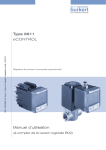
Type8611
eCONTROL
Process controller and Ratio controller
Operating Instructions
(Valid from software version B02)
We reserve the right to make technical changes without notice.
Technische Änderungen vorbehalten.
Sous réserve de modification technique.
© Bürkert SAS , 2010-2015
Operating Instructions 1501/5_EUen_00805625 / Original: DE
Type 8611

eCONTROL 8611: Process Controller and Ratio Controller
Contents
1.
Operating Instructions.........................................................................................................................................................6
1.1.
2.
Symbols....................................................................................................................................................................................6
Authorized use..............................................................................................................................................................................7
2.1.
Restrictions..............................................................................................................................................................................7
2.2.
Predictable Misuse..............................................................................................................................................................7
3.
Basic Safety Instructions..................................................................................................................................................8
4.
General Information.................................................................................................................................................................9
5.
6.
7.
4.1.
Contact Addresses..............................................................................................................................................................9
4.2.
Warranty....................................................................................................................................................................................9
4.3.
Information on the Internet.............................................................................................................................................9
System Description.................................................................................................................................................................10
5.1.
General Description.........................................................................................................................................................10
5.2.
Functions...............................................................................................................................................................................11
5.3.
The various mounting and installation models.................................................................................................11
5.4.
Software.................................................................................................................................................................................11
Technical Data..............................................................................................................................................................................12
6.1.
Operating Conditions......................................................................................................................................................12
6.2.
Conformity with the following standards.............................................................................................................12
6.3.
General Technical Data..................................................................................................................................................12
6.4.
Rating plate description.................................................................................................................................................13
6.5.
Electrical Data.....................................................................................................................................................................14
Assembly............................................................................................................................................................................................16
7.1.
Assembly models..............................................................................................................................................................16
7.2.
Attachment to a proportional valve.........................................................................................................................17
english
3
Type 8611

7.3.
8.
9.
10.
Assembly of the control cabinet model................................................................................................................18
Electrical Installation.......................................................................................................................................................20
8.1.
Electrical installation for fitting assembly, wall assembly, valve assembly or rail assembly
models....................................................................................................................................................................................20
8.2.
Electrical installation of the control cabinet model........................................................................................24
Operation and Function.....................................................................................................................................................27
9.1.
Control and display elements.....................................................................................................................................27
9.2.
Operating levels and operating states..................................................................................................................28
9.3.
Function of the keys........................................................................................................................................................29
Operating Structure.............................................................................................................................................................30
10.1. Operating structure of the process operating level in MANUAL operating state..........................30
10.2. Operating structure of the configuration level..................................................................................................31
11.
Functions of the Process Operating Level....................................................................................................37
11.1. Operating state AUTOMATIC......................................................................................................................................37
11.2. Operating state MANUAL..............................................................................................................................................38
11.3. Specific menu options of process and ratio control......................................................................................38
11.4. Menu options in the MANUAL operating state..................................................................................................38
11.5. SET - Set-point value default for process control..........................................................................................39
11.6. RFAC - Ratio factor default for ratio control.......................................................................................................39
11.7. TEST – Display of the analog inputs and outputs and the digital inputs...........................................40
11.8. PARA – Display and optimization of the controller parameters..............................................................41
11.9. VALV – Manual opening and closing of the connected actuating elements.....................................42
12.
Functions of the Configuration Level................................................................................................................44
12.1. General Description.........................................................................................................................................................44
12.2. Menu options of the configuration level...............................................................................................................45
12.3. MODE - Selection of control variable, actuating element and process value input.....................46
12.4. UNIT - Selection of measuring units and decimal places..........................................................................59
4
12.5. SETP / RFAC - Selection and scaling of set-point value default / entry of ratio factor.............62
english
Type 8611

12.6. S_IN - Scaling of sensor input signal (4 - 20 mA or 0 - 10 V).......................................................................................................64
12.7. AOUT - Scaling of analog output
(4 - 20 mA or 0 - 10 V)....................................................................................................65
12.8. CALI - Calibration of the analog inputs and outputs.....................................................................................67
12.9. Calibration of the assembly models: Wall, rail, valve or fitting assembly...........................................................................................................................68
12.10. Calibration of the control cabinet model..............................................................................................................69
12.11. KFAC - Entry of K-factor for flow-rate measurement....................................................................................70
12.12. FILT - Filtering of the process actual value input............................................................................................72
12.13. PARA - Adjusting the controller parameters......................................................................................................73
12.14. B_IN - Configuration of binary input.......................................................................................................................81
12.15. B_O1 - Configuration of the binary output..........................................................................................................82
12.16. B_O2 - Second binary output.....................................................................................................................................90
12.17. VALV - Test function and setting of the control range..................................................................................91
12.18. CODE - Code protection...............................................................................................................................................93
12.19. DSPL - Setting the display...........................................................................................................................................94
12.20. FACT - Reset to Factory Settings.............................................................................................................................95
12.21. U_xx, B_xx - Display of the program version and software version......................................................95
12.22. END - Leaving the configuration level...................................................................................................................96
13.
Overview Setting parameters.......................................................................................................................................97
14.
Maintenance, Troubleshooting..................................................................................................................................98
14.1. Malfunctions.........................................................................................................................................................................98
15.
Packaging and Transport................................................................................................................................................99
16.
Storage...............................................................................................................................................................................................99
17.
Disposal.............................................................................................................................................................................................99
5
english
Type 8611
Operating Instructions
1.
Operating Instructions
The operating instructions describe the entire life cycle of the device. Keep these instructions in a location which is
easily accessible to every user, and make these instructions available to every new owner of the device.
Warning!
The operating instructions contain important safety information!
Failure to observe these instructions may result in hazardous situations.
• The operating instructions must be read and understood.
1.1.
Symbols
Danger!
Warns of an immediate danger!
• Failure to observe the warning will result in a fatal or serious injury.
Warning!
Warns of a potentially dangerous situation!
• Failure to observe the warning may result in serious injuries or death.
Caution!
Warns of a possible danger!
• Failure to observe this warning may result in a moderate or minor injury.
Note!
Warns of damage to property!
• Failure to observe the warning may result in damage to the device or the equipment.
Indicates important additional information, tips and recommendations.
refers to information in these operating instructions or in other documentation.
→→designates a procedure which you must carry out.
6
english
Type 8611
Authorized use
2.
Authorized use
Non-authorized use of the process controller Type 8611 may be a hazard to people, nearby equipment
and the environment.
• The process controller is intended for controlling the process variables for pressure, temperature or flow-rate
in conjunction with a proportional or process valve and a sensor.
• Do not use the device outdoors.
• Use according to the authorized data, operating conditions and conditions of use specified in the contract
documents and operating instructions. These are described in the chapter entitled "Technical Data".
• The device may be used only in conjunction with third-party devices and components recommended and
authorized by Bürkert.
• Correct transportation, correct storage and installation and careful use and maintenance are essential for reliable and faultless operation.
• Use the device only as intended.
2.1.
Restrictions
If exporting the system/device, observe any existing restrictions.
2.2.
Predictable Misuse
• The Type 8611 is not to be used in areas where there is a risk of explosion.
• Do not physically stress the housing (e.g. by placing objects on it or standing on it).
7
english
Type 8611
Basic Safety Instructions
3.
Basic Safety Instructions
These safety instructions do not make allowance for any
• contingencies and events which may arise during the installation, operation and maintenance of the devices.
• local safety regulations – the operator is responsible for observing these regulations, also with reference to the
installation personnel.
General Hazardous Situations.
To prevent injury, ensure that:
• any installation work may be carried out by authorized technicians and with the appropriate tools only.
• after an interruption in the power supply or pneumatic supply, ensure that the process is restarted in a defined
or controlled manner.
• the device may be operated only when in perfect condition and in consideration of the operating instructions.
• the general rules of technology apply to application planning and operation of the device.
Note!
Electrostatic sensitive components / modules!
The device contains electronic components, which react sensitively to electrostatic discharge (ESD). Contact
with electrostatically charged persons or objects is hazardous to these components. In the worst case scenario,
they will be destroyed immediately or will fail after start-up.
• Observe the requirements in accordance with EN 61340-5-1 and 5-2 to minimize or avoid the possibility of
damage caused by sudden electrostatic discharge!
• Also, ensure that you do not touch electronic components when the power supply voltage is present!
The process controller Type 8611 was developed with due consideration given to the accepted safety rules
and is state-of-the-art. Nevertheless, dangerous situations may occur.
Failure to observe this operating manual and its operating instructions as well as unauthorized tampering
with the device release us from any liability and also invalidate the warranty covering the devices and
accessories!
8
english
Type 8611
General Information
4.
General Information
4.1.
Contact Addresses
Germany
Bürkert Fluid Control Systems
Sales Center
Christian-Bürkert-Str. 13-17
D-74653 Ingelfingen
Tel. + 49 (0) 7940 - 10 91 111
Fax + 49 (0) 7940 - 10 91 448
E-mail: [email protected]
International
Contact addresses can be found on the final pages of the printed operating instructions.
And also on the Internet at:
www.burkert.com
4.2.
Warranty
The warranty is only valid if the device is used as intended in accordance with the specified application
conditions.
4.3.
Information on the Internet
The operating instructions and data sheets for Type 8611 can be found on the Internet at:
www.burkert.com
9
english
Type 8611
System Description
5.
System Description
5.1.
General Description
The process controller Type 8611 is designed for integration in a closed control circuit and can be used for
numerous control tasks in fluid technology. The figure below illustrates the integration of the controller in a closed
control circuit.
Controlled system
Controller 8611
Set-point SP
(set-point value)
+
Manipulated
variable MV
Controlled
variable
_
Actuating
element
X
Sensor
Process
Feedback process actual value (PV)
Figure 1:
Block diagram of a closed control circuit
5.1.1.
Interfaces of the process controller Type 8611
Depending on the controlled system and process, different controller structures and different inputs/outputs are
available for measuring the process actual value and for controlling the actuating elements. The diagram below
shows the available interfaces of the process controller.
Analog output
4 - 20 mA / 0 - 10 V
Inputs
Operation
Figure 2:
Interfaces of the process controller Type 8611
english
Transistor outputs
PWM, 2P – T, 3P – T
Process value output
4 - 20 mA / 0 - 10 V
Binary output 0 / 24 V
(NC / NO)
Binary input 0-30 V DC
10
Outputs
eCONTROL
Type 8611
Ext. set-point value default
or ratio
4 - 20 mA / 0 - 10 V
Sensor inputs
4 - 20 mA / 0 - 10 V,
frequency, Pt 100
Process
controller
Interfaces
24 / 5 V DC
electrical power supply
for sensors
Supply
Supply 24 V DC
RS485
option, for control
cabinet model only
Type 8611
System Description
5.2.
Functions
The following control tasks can be executed with the process controller Type 8611 eCONTROL.
• Fixed command control (single-loop control circuit)
• Sequential control (external set-point value)
• Ratio control
• Cascade control
Standard signals (current / voltage) and frequency-analog signals can optionally be applied or resistance thermometers (Pt 100) can be connected to the scalable controller inputs.
Outputs for continuous standard signals (current / voltage) or transistor outputs can be used as controller outputs.
Valves or other switching actuators can be operated via the transistor outputs. One binary output and up to 2 binary
outputs for auxiliary functions are additionally provided.
5.3.
The various mounting and installation models
The process controller Type 8611 is available in the following models (see also chapter “7.1. Assembly models”):
• For installation in a pipeline system
• For attachment to a proportional valve
• For wall assembly or for assembly on a rail
• For installation in a control cabinet
Particularities of the control cabinet model:
Unlike the remaining assembly models, the cabinet model of type 8611 has not one but two binary
outputs.
5.4.
Software
In the following description of the menu options and their operating structures, the entire software of the eCONTROL
Type 8611 is explained. This complete software scope is only available for the control cabinet model of the eCONTROL
Type 8611.
The menu structure may vary depending on the device model (wall, valve, rail or fitting assembly). In accordance
with the device model, only menu options that are logically purposeful for the application area can be selected. This
pre-selection is made upon delivery of the controller in accordance with the chosen order part number.
11
english
Type 8611
Technical Data
6.
Technical Data
6.1.
Operating Conditions
Permitted ambient temperature:
(operation and storage) 0 ... +70 °C
Max. permitted humidity: ≤ 80 %, non condensing
Protection class: IP65 to EN 60529
6.2.
Conformity with the following standards
CE mark conforms to
EMC Directive:
6.3.
EN61326
General Technical Data
Materials
Housing, cover: PC, + 20 % glass fiber
Front plate foil: Polyester
Screws: Stainless steel
Multipin: CuZn, nickel-plated
Wall assembly bracket: PVC
Assembly
Installation position: Any position
Assembly models:Attachment to a pipeline with Bürkert flow-rate fitting Type S030
wall assembly, rail assembly, valve assembly, control cabinet assembly
Display: 2-line, (see “Figure 10: Display elements”)
Operating voltage: Multipin: 3-pin or / and 4-pin M8, 8-pin M12
Power cable: 0.5 mm2 max. cross section,
max. 100 m long, screened
12
english
Type 8611
Technical Data
6.4.
Rating plate description
The rating plate contains important technical data for the specific device. The structure of the rating plate is
described below by way of example.
6.4.1.
Rating plate of the controllers for wall, rail, valve or fitting
assembly
Controller type
Assembly model
- Wall (wall assembly)
- Rail (rail assembly)
- Valve (assembly directly on valve)
- Fitting (assembly directly on flow-rate fitting)
Example:
8611 Wall 24VDC
IN:Norm
OUT:Norm
SET: Norm ACT: PWM
S/N xxxxxx
00177462
W16LU
6.4.2.
Sensor input signal (Norm, Pt 100 or Freq (NPN))
Analog output (Norm or None)
Controller output signal (PWM or NORM)
Set-point value input signal
Manufacturer's code
Order part number
Serial number
Figure 3:
Power supply voltage
Example: Rating plate of the controllers for wall, rail, valve or fitting assembly
Rating plate of the control cabinet model
Controller type
Assembly model
- Panel (control cabinet)
Example:
8611 Panel 24VDC
Prozessregler
Controller design
Serial number
S/N xxxxxx
00210206
Power supply voltage
W16LU
Manufacturer's code
Order part number
Figure 4:
Example: Rating plate of the control cabinet model
13
english
Type 8611
Technical Data
6.5.
Electrical Data
Operating voltage: 24 V DC ±10 %, filtered and controlled
Power consumption without load: approx. 2 W
with load: maximum 48 W
100 % ED: 36 W
Controller sampling rate: 6.5.1.
300 Hz
Inputs
Set-point value
Standard 4 - 20 mAInput impedance:
Resolution:
70 Ω
5.5 µA
Standard 0 - 10 VInput impedance:
Resolution:
11.5 kΩ
2,5 mV
Sensors
Standard 4 - 20 mAInput impedance:
Resolution:
70 Ω
5.5 µA
Frequency
Input 1External sensor
Frequency range:
Input resistance:
Signal types:
min. 0.25 Hz / max. 1 kHz
> 1 kΩ
Sine, rectangle, triangle (> 3000 mVss,
max. 30 Vss)
Input 2Internal Hall sensor
Frequency range:
min. 0.25 Hz / max. 1 kHz
(only in conjunction with Bürkert flow-rate fitting
Type S030)
Pt 100 (2-wire)Measuring range:
Measured current:
Measuring error:
0 °C ... 200 °C
1 mA
< 0.5 °C
Binary inputInput impedance:
Response threshold:
Max. frequency:
10 kΩ
3 ... 30 V
1 kHz
14
english
Type 8611
Technical Data
6.5.2.
Outputs
Continuous signalStandard signal 4 - 20 mA
Max. loop resistance:
Precision:
680 Ω
0,5 %
Standard signal 0 - 10 V
Maximum current:
Precision:
20 mA
0,5 %
Discontinuous signal2 transistor outputs for PWM or PTM control
Control frequency:
1.2 kHz ... 20 Hz
Max. resolution:
16 bit (depending on frequency)
Max. current per unit area: 1.5 A
Switching voltage:
24 V DC
Binary outputTransistor output (PNP) configurable
Max. current per unit area: 1.5 A
Switching voltage:
24 V DC
Sensor supply:
24 V DC
Total load for all outputs:
1,5 A
15
english
Type 8611
Assembly
7.
Assembly
7.1.
Assembly models
Attachment to a Bürkert flow-rate fitting
Attachment to a proportional valve
Bürkert
flow-rate fitting
Type SO30
Installation in a control cabinet
Wall assembly or rail assembly
The description of the installation in a control
cabinet and the device dimensions can be found in
the following chapter “7.3. Assembly of the control
cabinet model”.
Table 1:

Adapter
for wall assembly
Adapter
for rail assembly
Assembly models
7.1.1.
Assembly accessories
Model
Accessories
Order no.
Installation in pipeline
Flow-rate fitting, Type S030
See data sheet S030
Rail assembly
Adapter for rail assembly
655980
Wall assembly
Adapter for wall assembly
427098
The adapters for the wall and rail assembly are included in the scope of supply of the assembly model.
16
Table 2:
Assembly accessories
english
Type 8611
Assembly
7.2.
Attachment to a proportional valve
Attach the process controller Type 8611 to a proportional valve as described below.
→→Loosen the 4 screws at the front of the process controller.
Note!
Be careful when opening the process controller so as not to damage the internal cabling.
• Remove the cover carefully from the housing without jerks.
→→Remove the cover carefully from the housing.
→→Place the supplied flat seal over the contact tabs.
→→Attach the housing of the process controller on the contact tabs and fasten with the valve screw.
→→Check the correct position of the profile gasket at the housing of the process controller.
→→Place cover on the housing of the process controller and fasten with 4 screws.
If necessary, the cover can also be mounted in a position rotated by 90 ° to the left or the right.
Proportional valve
Housing of the process controller
Cover of the
process controller
Contact tabs
Flat seal
Valve screw
Profile gasket
4 screws for fastening the cover
Figure 5:
Attachment of the process controller to a proportional valve
17
english
Type 8611
Assembly
7.3.
7.3.1.
Assembly of the control cabinet model
Device dimensions and control panel cut-out
66
54.2
76
29
44.5
Control panel cut-out for the installation
R3
45

Figure 6:
Device dimensions and control panel cut-out
18
english
Type 8611
Assembly
7.3.2.
Installation in a control cabinet
• Prepare control panel cut-out with the dimensions 45mm x 45mm (corner radius 3mm).
• Place the supplied seal on the housing.
• Insert the controller from the front into the control panel cut-out.
• From the rear, snap the 4 supplied fastening elements into place and fasten using a screwdriver.
4 Fastening elements
Seal

Figure 7:
Installation elements
Figure 8:
Installed controller
Recommended line cross sections for the control cabinet model:
Cross section
min.
Cross section for flexible lines
0.2 mm²
Cross section for flexible lines with cable end
sleeve without plastic sleeve
0.25 mm²
Cross section for flexible lines with cable end
sleeve with plastic sleeve
0.25 mm²
Table 3:
Cross section
max.
Minimum length
1.5 mm²
10 mm (stripping)
1.5 mm²
10 mm
0.75 mm²
10 mm
Recommended line cross sections
19
english
Type 8611
Electrical Installation
8.
Electrical Installation
8.1.
Electrical installation for fitting assembly, wall
assembly, valve assembly or rail assembly models
8.1.1.
Connection versions
Connector
Connector view
Circular plug-in
connector
M12, 8-pole
5
6
4
7
3
1
Circular plug-in
connector
M8, 3-pole
Circular plug-in
connector
M8, 4-pole
2
8
3
2
4
1
3
Connection sensor
(4 - 20 mA / 0 - 10 V, Pt 100 or frequency)
and sensor supply 24 V DC
Connection actuating element
• Proportional valve (1 x PWM)
• Process valve (1 x PTM)
• Manipulated variable 4 - 20 mA / 0 - 10 V and
sensor supply 24 V DC (only ID 182383)
Connection for direct assembly on proportional valve (1 x PWM) or
open/closed valve (1 x PTM)
DIN-EN 175301
2
Table 4:
Power supply voltage,
set-point input 4 - 20 mA / 0 - 10 V,
process actual value or position set-point output 4 - 20 mA / 0 - 10 V,
binary input,
binary output
Note!
A straight plug (female) is recommended for the connecting cable,
as the alignment of the plug can vary.
4
1
Configuration
1
Connection versions for assembly on flow-rate fitting, wall assembly, rail assembly or valve assembly
20
english
Type 8611
Electrical Installation
8.1.2.
Pin assignment
Circular plug-in connector M12, 8-pole
A straight connector (female) is recommended for the connecting cable as the orientation of the connector may vary.
Connector
diagram
5
6
4
7
3
1
8
2
Table 5:
Pin
Color
Configuration
1
white
24 V DC power supply
2 (DIN2)
brown
Binary input (B_IN)
3
green
GND – Power supply, binary input, binary output
4 (AOUT)
yellow
4 - 20 mA or 0 - 10 V analog output
(process value or manipulated variable for valve)
5 (AIN2)
grey
4 - 20 mA or 0 - 10 V analog input (set-point value / ratio)
6
pink
GND – Analog output
7
blue
GND – Analog input (set-point value / ratio)
8 (BO1)
red
(+) Binary output (B_O1)
Configuration of circular plug-in connector M12, 8-pole
Wire colors when using standard cables (e.g. from Lumberg, Escha)
8.1.3.
Sensor connection
Circular plug-in connector M8, 3-pole
4
1
3
Input signal
Pin Color
Configuration
External circuit
1
1
4 - 20 mA
2-wire supply of Type
3
8611
brown
+ 24 V sensor supply
blue
not connected
(AIN1)
black
Signal input (source)
4
I
24 V DC
Transmitter
4
4 - 20 mA / 0 - 10 V 1
3-wire supply of Type
3
8611
brown
+ 24 V sensor supply
1
blue
GND
3
(AIN1)
4
black
Signal input (source)
4 - 20 mA / 0- 10 V
4-wire external
supply
1
brown
not connected
3
blue
GND
(AIN1)
4
black
Signal input (source)
4
4 - 20 mA
24 V DC
GND
Transmitter
4 - 20 mA / 0 - 10 V
GND
3
4
GND
Transmitter
4 - 20 mA / 0 - 10 V Supply
21
english
Type 8611
Electrical Installation
Input signal
Pin Color
Configuration
External circuit
1
Frequency
3-wire supply of Type
3
8611
brown
+ 24 V sensor supply
1
blue
GND
3
(DIN1)
4
black
Frequency input (NPN)
Frequency
4-wire external
supply
1
brown
not connected
3
blue
GND
(DIN1)
4
black
Frequency input (NPN)
1
brown
not connected
3
blue
GND Pt 100
4
black
(+) Pt 100 (power supply)
Pt 100
(2-wire)
(AIN3)
Table 6:
24 V DC
GND
4
Transmitter
Clock (DIN1)
GND
GND
3
4
Transmitter
Clock (DIN1)
Supply
Pt 100
3
4
Sensor connection: Configuration of circular plug-in connector M8, 3-pole
8.1.4.
Valves connection
Circular plug-in connector M8, 4-pole
2
4
1
3
Output
signal:
Pin
Color
Configuration
1
brown
not connected
PWM
2
white
not connected
(MODE =
SCV)
3
blue
(–) PWM (valve2)
4 (BO4)
black
(+) PWM (valve2)
1 (BO3)
brown
(+) Aeration (valve 1)
3-point
2
white
(–) Aeration (valve 1)
(MODE =
PCV)
3
blue
(–) Deaeration (valve 2)
1)
4 - 20 mA
or 0 - 10 V
(MODE =
4 – 20 /
0 – 10)
External circuit
3
1
3
(+) Deaeration (valve 2)
1 (BO3)
brown
+ 24 V DC supply
2
white
GND (4 - 20 mA or 0 - 10 V)
2
3
blue
GND supply
3
+ 4 - 20 mA or
0 - 10 V manipulated variable
4
english
NO valve
4
black
22
NC valve
2
4 (BO4)
4 (AOUT) black
Proportional
valve
4
1
Supply of 8611
M
Type 8611
Electrical Installation
Output
signal:
Pin
Color
Configuration
External circuit
1 (BO3)
brown
(+) Valve 1
1
3-point
2
white
(–) Valve 1
(MODE =
3P – T)
3
blue
(–) Valve 2
1)
4 - 20 mA
or 0 - 10 V
(MODE =
4 – 20 /
0 – 10)
External
supply
2-point
(MODE =
2P – T)
3
black
(+) Valve 2
1
brown
+ 24 V DC supply (max. 1A)
2
white
GND (4 - 20 mA or 0 - 10 V)
3
blue
GND supply
4
(AOUT)
black
+ 4 - 20 mA or
0 - 10 V manipulated variable
4
1 (BO3)
brown
(+) Valve 1
1
white
(–) Valve 1
3
blue
not connected
4
black
not connected
NC / NO valve
4
4 (BO4)
2
NC / NO valve
2
External supply
+ 24 V DC
2
M
GND
NC / NO valve
2
1)Only available for identification number 182383
Table 7:
Configuration of circular plug-in connector M8, 4-pole
Circular plug-in connector M12, 8-pole
5
6
4
7
3
1
8
2
Output
signal:
2)
4 - 20 mA
or 0 - 10 V
(MODE =
4 – 20 /
0 – 10)
Pin
Color
4
yellow
(AOUT)
6
pink
Configuration
External circuit
4 - 20 mA or
0 - 10 V manipulated variable
4
GND – Analog output
+ 24 V DC
M
GND (24 V)
6
2)Available for all models except for identification number 182383
Table 8:
Configuration of circular plug-in connector M12, 8-pole
23
english
Type 8611
Electrical Installation
8.2.
Electrical installation of the control cabinet model
Warning!
Risk of injury from incorrect installation!
Incorrect installation can damage or destroy the Type 8611 eCONTROL.
• The electrical installation may be performed by authorized electricians only!
1 2 3 4 5 6 7 8
Terminal block 1
9 10 11 12 13 14 15 16 17 18
19 20 21 22 23 24 25 26 27
Terminal block 2
Terminal block 3
Jumper 1
Jumper 2
Figure 9:
8.2.1.
Control cabinet model; connection PCB with spring terminals and jumpers
Terminal assignment
Terminal block 1
Terminal Configuration
1
GND – Electrical power supply
External circuit
1
GND
2
24 V DC
24 V DC ± 10 %
max. residual ripple 10 %
2
24 V DC power supply
3
(BO2)
Binary output 2 (B_O2)
3
(1, 6, 8, 11, or 23
24 V / 0 V (max. 1 A) NC / NO
GND)
4
(BO1)
Binary output 1 (B_O1)
4
(1, 6, 8, 11, or 23
24 V / 0 V (max. 1 A) NC / NO
GND)
24
english
Type 8611
Electrical Installation
Terminal Configuration
5
(BO3)
(+) Aeration valve (PCV) or
valve 1 (2P – T or 3P – T)
6
(–) Aeration valve (PCV) or
valve 1 (2P – T or 3P – T)
7
(BO4)
(+) Proportional valve (SCV),
bleed valve (PCV) or valve 2
(3P – T)
8
(–) Proportional valve (SCV),
bleed valve (PCV) or valve 2
(3P – T)
Table 9:
External circuit
5
MODE = 2P – T
or 3P – T
6
MODE = PCV
5
6
NC / NO
valve max. 1 A
NC
valve max. 1 A
MODE = 3P – T
MODE = SCV
MODE = PCV
7
7
7
8
8
8
NC / NO
valve max. 1 A
NC
valve max. 1.5 A
NO
valve max. 1 A
Configuration of terminal block 1
Terminal block 2
Terminal Configuration
External circuit
GND – Analog output
10
(AOUT)
(+) Analog output (process value or
manipulated variable
for valve)
10
4 - 20 mA / 0 - 10 V
11
GND – Sensor, actuating element
11
GND
12
24 V DC sensor supply or actuating
element
12
24 V DC
13
not used
14
(AIN2)
(+) External set-point value / ratio
4 - 20 mA / 0 - 10 V
15
(+) 5 V DC sensor supply (max. 20 mA)
16
RS485_COM
16
RS485_COM
17
RS485_A (+)
17
RS485_A
18
RS485_B (–)
18
RS485_B
Table 10:
9
GND
9
not used
14
(21
15
(1, 11, or 23
4 - 20 mA / 0 - 10 V (Source)
A-GND)
5 V DC
GND)
Configuration of terminal block 2
25
english
Type 8611
Electrical Installation
Terminal block 3
Terminal
Configuration
19
GND – Pt 100, RTD
20
(AIN3)
(+) Pt 100, RTD (power supply)
External circuit
19
Pt 100
(0 ... 200 °C)
20
21
GND – Analog input
21
A-GND
22
(AIN1)
(+) Process value input
4 - 20 mA / 0 - 10 V
22
21
4 - 20 mA / 0 - 10 V (source)
A-GND
23
GND – Sensor, actuating element
23
GND
24
24 V DC sensor supply or
actuating element
24
23
24 V DC - Out (max. 1 A)
GND
25
Supply of
Type 8611
(DIN3)
Frequency input 2
(NPN or PNP)
Jumper 2
Q2 for ratio control
(MODE = RATI)
NPN
Supply of 8611
12 or 24
11 or 23
25
PNP
25
External
supply
(DIN3)
Frequency input 2
(NPN or PNP)
Jumper 2
Q2 for ratio control
(MODE = RATI)
NPN
11 or 23
25
26
(+) Binary input
(DIN1)
27
External
supply
(DIN1)
Table 11:
Clock
GND
Transmitter
Clock
GND
0 ... 2.7 V (log. 0)
max. 1 kHz
3 ... 30 V (log. 1)
1, 11, or 23
Supply of
Type 8611
Transmitter
Supply
(DIN2)
27
GND
External supply
PNP
26
24 V DC
Frequency input 1
(NPN or PNP)
Jumper 1
Actual value flow-rate /
Q1 for ratio control
(MODE = RATI)
NPN
Frequency input 1
(NPN or PNP)
Jumper 1
Actual value flow-rate /
Q1 for ratio control
(MODE = RATI)
NPN
Configuration of terminal block 3
26
english
PNP
GND
Supply of 8611
12 or 24
11 or 23
27
24 V DC
GND
Transmitter
Clock
External supply
Supply
PNP
11 or 23
27
GND
Clock
Transmitter
GND
Type 8611
Operation and Function
9.
Operation and Function
9.1.
Control and display elements
The control and display element of the eCONTROL Type 8611 is equipped with 3 buttons and an LCD-Matrix
display.
9.1.1.
Display elements
4-character display
7-character matrix for numerical values
4-character display
14-character matrix for measuring units and parameter
designations
10-segment bar graph for display of the manipulated
variable in % (One Segment indicates 10 % of
manipulated variable)
Red LED is lit in case of an alarm
Is displayed for external set-point value default
Is displayed when the control is activated
Indicates the operating state MANUAL
Figure 10:
9.1.2.
Display elements
Control elements
Arrow keys
• Change the display at the process operating level in AUTOMATIC operating
state
left
right
• Change the menu options in MANUAL operating state and at the
configuration level
• Entering of numerical values
ENTER button
• Switches between the operating states AUTOMATIC and MANUAL
• Switches between operating and configuration level
• Selection of menu option
• Take over settings
The detailed description of the function can be found in chapter “9.3. Function of the keys”.
english
27
Type 8611
Operation and Function
9.2.
Operating levels and operating states
2 operating levels and 2 operating states AUTOMATIC and MANUAL are available for the operation and setting
of the eCONTROL Type 8611.
Level 1: Process operating level
At level 1, the user can switch between 2 operating states AUTOMATIC and MANUAL.
Operating state:
AUTOMATIC: The normal control mode is executed and monitored.
MANUAL: Quick access to important functions and test functions.
The operating state MANUAL is indicated on the display by a hand
symbol.
Level 2: Configuration level
At level 2, the user can change the basic settings of the controller.
After switching on the operating voltage, the controller is at the process operating level and in the AUTOMATIC
operating state.
When the operating voltage is applied, the software version will light up on the display for approx. 2 seconds. If
the ENTER key is pressed during these 2 seconds, the sub-version is displayed. After this, the controller is once
again at the process operating level.
9.2.1.
Switching between the operating levels and operating
states
The ENTER key is pressed to change the operating level and operating state (see Figure 11).
Any changes made within the configuration level are only stored after returning to the process operating
level.
Changes in the MANUAL operating state can be made while the controller is running.
Configuration level
Process operating level
Operating state
AUTOMATIC
Press
button
eCONTROL 8611
> 5 s (long)
eCONTROL 8611
025.5
MODE
L /M
0..... 9
O
u
t
< 1 s (short)
ENTER
Operating state
MANUAL
BACK
END
VALV
Changing the operating level and operating state
english
ENTER
TEST
PARA
Figure 11:
O
u
t
MODE
UNIT
.
.
.
.
SET
28
0..... 9
Type 8611
Operation and Function
9.3.
Function of the keys
The device is operated using two arrow keys and one ENTER key.
The function of these in respect of the operating level and the operating state is shown in Table 12 below.
Operating
level
Operating
state
AUTOMATIC
Level 1:
Process
operating level
Switch display between actual value,
set-point value and manipulated
variable
Switches to the
last menu option
MANUAL
Level 2:
Configuration
level
• Press and hold key (> 5 s):
Switches to configuration level
• Selection of menu option
• Take over settings
Entering of values
Increase value
Change by one
position to the left
Switches to the
last menu option
Switches to the
next menu option
Entering of values
Increase value
Table 12:
Switches to the
next menu option
• Press key briefly (< 1 s):
Switches to operating state MANUAL
Change by one
position to the left
• Switches to operating state AUTOMATIC (for display BACK)
• Selection of menu option
• Take over settings
• Switches to process operating level
and to operating state AUTOMATIC
(for display END)
Function of the keys
29
english
Type 8611
Operating Structure
10.
Operating Structure
10.1. Operating structure of the process operating level
in MANUAL operating state
SET ***)
RFAC ****)
***) The SET menu option is
only displayed for process
control.
Consequently for all control
variables set in the MODE
menu except for RATI.
Enter set-point value
Enter ratio factor
BACK
AIN1
TEST
****) The RFAC menu option
is only displayed for ratio
control.
Consequently only if the
RATI control variable is set in
the MODE menu.
AIN2
AIN3
DIN1
DIN2
DIN3
**) Code query only when code
protection is activated
(see chapter 12.18)
AOUT
BACK
CODE **)
KP1
PARA
KP2 *)
*)The display depends on the
control variable set in the
MODE menu
(see chapter 12.3)
TREG *)
TN *)
DEAD
KP T *)
TN T *)
DE T *)
BACK
150
VALV *)
L/H
055 PRZ *)
Back to
AUTOMATIC operating state
30
Figure 12:
Operating structure of the process operating level in MANUAL operating state
english
Type 8611
Operating Structure
10.2. Operating structure of the configuration level
Configuration level
CODE
MODE
Enter access code if the code protection has been activated in the CODE menu.
CODE
RATI
„0001“
FREQ
NORM
F
P
SCV
PCV
T
T–F
T+F
L
X
UNIT *
Select
control frequency
(PWM)
Select
control times
2P – T
Select
control times
3P – T
Select
control times
FREQ *
PT *
NORM *
4 – 20
0 – 10
*)The display depends on the control variable set in the MODE
menu.
Q1 **)
Q2 **)
**)Q1 and Q2 are only displayed if ratio control = RATI has been
set in the MODE menu.
MODE = RATI
MODE = F
L/H
1
L/M
0.1
G/H
0.01
G/M
ML / M
M3 / H
MODE = T
MODE = T+F, T-F
See Chapter 12.3
°C
°F
NU
MODE = P
BAR
RBAR
MBAR
PSI
UNIT, MODE = L, MODE = X
Figure 13:
Operating structure of the configuration level - 1 of 6
31
english
Type 8611
Operating Structure
MODE = L
UNIT *)
MM
1
CM
0.1
M
0.01
*)The display depends on
the control variable set in
the MODE menu
(see chapter 12.3)
Ft
In
NU
MODE = X
PH
µS/c
mS/c
S/c
Ωxc
ppm
SETP **)
EXT
4 – 20
RFAC ***)
INT
0 – 10
S_IN ****)
4 – 20
Enter
scaling
Enter
scaling
0 – 10
AOUT
4 – 20
FLOW *)
0 – 10
TEMP *)
Enter
scaling
**) The SETP menu option is
only displayed for
process control.
Consequently for all
control variables set in the
MODE menu except for
RATI.
***) The RFAC menu option
is only displayed for ratio
control.
Consequently only if the
RATI control variable is
set in the MODE menu.
PRES *)
LEVL *)
VAL *)
POS *)
Q1 *)
Q2 *)
RFAC *)
CALI
Calibration of analog inputs and outputs
KFAC
32
Figure 14:
Operating structure of the configuration level - 2 of 6
english
****) The S_IN menu option is
only displayed if standard
signal (NORM) was
selected as sensor input.
Type 8611
Operating Structure
Select K-factor for ratio control
KFAC *)
Q1 **)
Q2 **
)
FREE
**)Q1 and Q2 are only displayed if frequency input (FREQ) was
selected for both flow-rate sensors in ratio control.
Enter value
0.01
0.1
1
10
The display 0.01, 0.1, 1 is used for setting the
decimal place.
Use the display 10 for setting the multiplier 10 for the
K-factor.
BACK
8081
QN0.6
QN1.5
Display value
QN2.5
QN3.5
QN6.0
8071
50L
Display value
100L
500L
S070
DN15
DN25
Display value
DN40
DN50
DN80
DN100
8031
100L
Display value
250L
S030
VA
DN06
8030
PVDF
DN08
PP
DN15
V2
PVC
DN20
OLD
MS
DN25
8012
8011
DN32
*) The KFAC menu option is not
indicated unless a sensor with
frequency input was selected in the
MODE menu.
DN40
DN50
Display value
Fitting S030 and the fitting of
devices 8030, 8011 and 8012,
DN15, exist in 2 versions. The
„v2“ marking can be found
either on the bottom or on the
side of the fitting.
FILT
Figure 15:
Operating structure of the configuration level - 3 of 6
33
english
Type 8611
Operating Structure
Enter filter factor ( 2 - 20)
FILT
PARA
KP1
KP2 *)
TREG *)
TN *)
*)The display depends on the
control variable set in the MODE
menu (see chapter 12.3)
DEAD
KP_T *)
TN_T *)
DE_T *)
INV
NO
YES
ZERO is only displayed
for entry INV / NO
ZERO
NO
STRT *)
YES
BACK
B _IN
NO
INV
HIGH
HOLD
LOW
SAFP
HIGH
PRZV **)
LOW
mA **
V **)
OPEN **)
CLOS **)
STOP **)
HIGH
OPEN
LOW
CLOS
OPEN **)
HIGH
CLOS **
LOW
)
B_O1 / B_O2
34
Figure 16:
Operating structure of the configuration level - 4 of 6
english
Enter value
)
**)The display depends on
the actuating element
set in the MODE menu
(see chapter 12.3)
Type 8611
Operating Structure
B _O1
NO
Selecting binary output as pulse output
PULS
Enter number
of pulses
DM3
1
IGAL
0.1
UGAL
0.01
M3
Selecting binary output as limit switch
LIMT
REL
ABS
Enter
hyteresis
values
FLOW *)
Enter process
limit value
PRES *)
*)The display depends on
the control variable set
in the MODE menu:
(see chapter 12.3)
TEMP *)
LEVL *)
VAL *)
POS
DLY XXX.X
Enter position
limit
INV
NO
HIGH
INV
YES
LOW
Selecting binary output as 2-state controller
2_P
REL
Enter
hysteresis
values
SP
Enter set
point limit
value
ABS
FLOW *)
Enter process
limit value
PRES *)
TEMP *)
LEVL *)
VAL *)
DLY XXX.X
B _O2 **)
INV
NO
HIGH
LED
NO
TEXT
NO
INV
YES
LOW
LED YES
TEXT
YES
**)The operating structure is identical to B_O1
VALV
Figure 17:
Operating structure of the configuration level - 5 of 6
35
english
Type 8611
Operating Structure
VALV
MODE = SCV, 4 - 20, 0 - 10: Continuous control
L/H *)
END
PRZ *
MIN
mA *)
MAX
)
*)The display depends on the
control variable set in the MODE
menu (see chapter 12.3)
V*
)
MODE = PCV, 2P - T, 3P - T: Quasi-continuous control
L/H *)
END
MIN
Enter MIN
MAX
Enter MAX
CODE
DSPL
NO
CMD
YES
BOTH
PVAL
SETP
FACT
NO
YES
U_xx
B_xx
END
36
Figure 18:
Display program version
xxxxx
Display software version
Switching to the process operating level – AUTOMATIC operating state
Operating structure of the configuration level - 6 of 6
english
Type 8611
Functions of the Process Operating Level
11.
Functions of the Process Operating
Level
11.1. Operating state AUTOMATIC
After switching on the operating voltage, the controller is at the process operating level and in the AUTOMATIC
operating state. The normal control mode is executed and monitored.
11.1.1. Displays in the AUTOMATIC operating state
Press the arrow keys to switch between 4 different displays for monitoring the control operation. Which of these
displays should be shown as start display after applying the operating voltage can be defined in the DSPL menu
(see “12.19. DSPL - Setting the display”).
eCONTROL 8611
025.5
025.5
L/M
L /M
0..... 9
O
u
t
Display process actual value
The display of the unit depends on the selection made in the
UNIT menu (see chapter 12.4).
For MODE = T – F or T + F the display switches between
temperature and flow-rate.
ENTER
For MODE = RATI the display switches between flow-rate Q1
and Q2.
030.0
0 3 SET
0.0
RFAC
Display set-point value
The display depends on the selection made in the MODE menu
(see chapter 12.3).
SET = Display for process control
RFAC = Display for ratio control
For MODE = T – F or T + F the display switches between
flow-rate set-point (SP_Q) and temperture set-point (SP_T).
For MODE = RATI the display switches between ratio factor
(RFAC) and flow-rate set-point (SPQ1).
025.5
030.0
065.0
0 6PRZV
5.0
0 6 5mA
.0
V
Figure 19:
Display process actual value
Display set-point value
Display manipulated variable for valve
Display depends on the actuating element selected in the
MODE menu (see chapter 12.3).
PRZV = Display pulse duty factor for solenoid valve
mA = Display manipulated variable in mA
V = Display manipulatec variable in V
Displays in the AUTOMATIC operating state
37
english
Type 8611
Functions of the Process Operating Level
11.2. Operating state MANUAL
Briefly press (< 1 s) the ENTER key to go to the MANUAL operating state. The operating state is indicated on the
display by a hand symbol.
11.3. Specific menu options of process and ratio control
The display of some menu options differs for the process and the ratio control. This is described in detail in the
respective menu descriptions.
The control type is specified by the control variable selected in the MODE menu:
• Process control: is active if all control variables have been selected in the MODE menu except forRATI.
• Ratio controlis active if the RATI control variable has been selected in the MODE menu
(see chapter “12.3.1. RATI - Selection of external sensors for ratio control”).
11.4. Menu options in the MANUAL operating state
SET
Set-point value default for process control
See chapter “11.5. SET - Set-point value default for process control”
• Menu option is displayed for process control.
• Is not available if external set-point value default is selected.
RFAC
Ratio factor default for ratio control
See chapter “11.6. RFAC - Ratio factor default for ratio control”
• Menu option is only displayed for ratio control (MODE = RATI).
• Is not available if external set-point value default is selected.
BACK
When BACK is displayed on the display, press the ENTER key briefly to switch to AUTOMATIC operating state.
When an arrow key is pressed, the next or respectively the previous menu option is
displayed.
TEST
Display of the analog inputs and outputs and the digital inputs.
See chapter 11.7
PARA
Adjusting the controller parameters (Code must be entered if code protection is activated).
See chapter “11.8. PARA – Display and optimization of the controller parameters”
VALV
Manual opening and closing of the connected valves.
See chapter 11.9
Table 13:
Menu options of the process operating level
38
english
Type 8611
Functions of the Process Operating Level
11.5. SET - Set-point value default for process control
In the case of process control, the set-point value default can be entered in the MANUAL operating state using
the SET menu.
Process control is active if all control variables have been set in the MODE menu except for RATI.
Setting the set-point value default in the menu:
Process operating level
Enter a value between 0.00 and 9999
(depends on the decimal places selected in the UNIT menu).
<1s
SET
030.0
*)Menu option is only available if internal set-point
value default was selected (see chapter “12.5.
SETP / RFAC - Selection and scaling of setpoint value default / entry of
ratio factor”).
SET *)
BACK
Back to operating state
AUTOMATIC
Figure 20:
SET; Set-point value default for process control
11.6. RFAC - Ratio factor default for ratio control
In the case of ratio control, the ratio factor can be entered in the MANUAL operating state using the RFAC menu.
The ratio control is active if the RATI control was set in the MODE menu.
Setting the ratio factor in the menu:
Process operating level
Enter a value between 00,00 and 99,99.
<1s
RFAC
00.00
% *)
BACK
*)Menu option is only available if internal set-point
value default was selected (see chapter “12.5.
SETP / RFAC - Selection and scaling of setpoint value default / entry of
ratio factor”).
Back to operating state
AUTOMATIC
Figure 21:
RFAC; Ratio factor default for ratio control
39
english
Type 8611
Functions of the Process Operating Level
11.7. TEST – D
isplay of the analog inputs and outputs
and the digital inputs
The analog inputs and outputs and the digital inputs are displayed while the controller is operating. No
changes can be made.
TEST
PARA
AIN1
Analog input 1: 4 - 20 mA or 0 - 10 V
(process value Q1 or Q2 for ratio control)
AIN2
Analog input 2: 4 - 20 mA or 0 - 10 V
(set-point value for process or ratio control)
AIN3
Analog input 3: Pt 100
(Process actual value temperature)
DIN1
Frequency input 1
(Process actual value flow-rate or Q1 for ratio control)
DIN2
Binary input: 0 / 1 corresponds to 0 V / 24 V input
DIN3
Frequency input 2
(Q2 for ratio control)
AOUT
Analog output 4 - 20 mA or 0 - 10 V (process actual value
or manipulated variable for actuating element)
BACK
Back to operating state
AUTOMATIC
Figure 22:
TEST; Display of the analog inputs and outputs and the digital inputs
40
english
Type 8611
Functions of the Process Operating Level
11.8. PARA – Display and optimization of the controller
parameters
In this menu of the process operating level, the controller parameters of the running process can be optimized.
The new controller parameters are taken over immediately after pressing the ENTER key.
The detailed description of the controller parameters depending on the selected process variable can be found in
chapter “11.8. PARA – Display and optimization of the controller parameters”.
Access to this menu can be protected by a user code (see chapter “12.18. CODE - Code protection”)
Enter code.
**)The display depends on the control variable
set in the MODE menu (see chapter 12.3)
0000
PARA
KP 1 **)
CODE *
)
KP 2 **)
TREG **)
Enter value
TN **)
VALV
*)Display is shown only if
code protection was activated in the CODE menu
(see chapter 12.18)
DEAD **)
KP T **)
0000
XXX
TN T **
)
DE T **)
BACK
Back to operating state
AUTOMATIC
Figure 23:
PARA; Display and optimization of the controller parameters
41
english
Type 8611
Functions of the Process Operating Level
11.9. VALV – M
anual opening and closing of the
connected actuating elements
If the VALV menu option is selected, the controller is stopped and the actuating element remains in the last
position. The manipulated variable can now by increased or lowered relatively to the last position by pressing
the key.
The display in the VALV menu option depends on the control variable set in the MODE menu:
• MODE = SCV, 0 - 10, 4 - 20, 2P - T, 3P - T (Reset time TN activated, TN > 0)
• MODE = PCV, 2P - T, 3P - T (Reset time TN deactivated, TN = 9999)
MODE = SCV, 0 - 10, 4 - 20, 2P - T, 3P - T (Reset time TN activated, TN > 0)
Display process value
150
VALV
L/H
In the case of cascaded control, the process value and
the flow-rate are displayed alternately
Actuating of Valve 1 (VLV1) (Increasing of the manipulated
variable, Bargraph length increases from left to right 3) 4)
SET
Actuating of Valve 1 (VLV1) (Decreasing of the manipulated
variable, Bargraph length decreases from right to left 3) 4)
055
PRZ
Back to operating state
AUTOMATIC
Figure 24:
Display manipulated variable (4 – 20, 0 – 10 or PRZ)
When leaving the VALV menu option, the last selected
manipulated variable is taken over.
VALV; Manual opening and closing of the actuating element
Changing the manipulated variable
Each time the key is pressed: MODE = SCV, 2P - T, 3P - T MODE = 4 - 20
MODE = 0 - 10
3) by 1%
by 0.2 mA
by 0.1 V
Continuous pressing of the key > 80 ms: Quick adjustment of the manipulated variable
4) The manipulated variable can be changed between 0 and 100 %.
Only for MODE = 3p - T the manipulated variable can be changed between -100 % and +100 %.
-100 % = Valve 2 is controlled by 100 % pulse duty factor
+100 % = Valve 1 is controlled by 100 % pulse duty factor
42
english
Type 8611
Functions of the Process Operating Level
MODE = PCV, 2P - T, 3P - T (Reset time TN deactivated, TN = 9999)
Display process value
VALV
150
L/H
In the case of cascaded control, the process value
and the flow-rate are displayed alternately
Actuating of valve 1 (VLV1) 5)
SET
Actuating of valve 2 (VLV2) 5)
Back to operating state
AUTOMATIC
Figure 25:
VALV; Manual opening and closing of the actuating element
Key functions
Each time the key is pressed: the actuating element is operated for 40 ms
Continuous pressing of the key > 80 ms: Continuous control of the actuating element
4) The detailed description of the VALV function can be found in chapter “12.17. VALV - Test function and
setting of the control
range”
43
english
Type 8611
Functions of the Configuration Level
12.
Functions of the Configuration
Level
12.1. General Description
In the following description of the menu options and their operating structures, the entire software of the eCONTROL
Type 8611 is explained. This complete software scope is only available for the control cabinet model of the eCONTROL
Type 8611.
The menu structure may vary depending on the device model (wall, valve, rail or fitting assembly). In accordance
with the device model, only menu options that are logically purposeful for the application area can be selected. This
pre-selection is made upon delivery of the controller in accordance with the chosen order part number.
Any changes made within the configuration level are only stored after returning to the process operating
level.
Access to the configuration level can be protected by a code. Any unauthorized persons are thus denied
access and cannot change the parameters.
If the code protection is activated, a code must be entered before switching to the configuration level
(see chapter “12.18. CODE - Code protection”).
44
english
Type 8611
Functions of the Configuration Level
12.2. Menu options of the configuration level
MODE
Selection of control variable, actuating element and process value input.
See Chapter 12.3
UNIT
Selection of measuring units and decimal places.
See chapter 12.4
SETP
Selection and scaling of set-point value default.
See chapter 12.5
RFAC
Entry of ratio factor for ratio control (MODE = RATI).
See chapter 12.5
S_IN
Scaling of sensor input signal ( 4 - 20 mA or 0 - 10 V).
See chapter 12.6
AOUT
Scaling of analog output (4 - 20 mA or 0 - 10 V).
See chapter 12.7
CALI
Calibration of the analog inputs and outputs.
See chapter 12.8
KFAC
Entry of K-factor for flow-rate measurement.
See chapter 12.11
FILT
Setting of the filtering factor.
See chapter 12.12
PARA
Setting of the controller parameters.
See chapter 12.13
B_IN
Configuration of the binary input.
See chapter 12.14
B_O1
Configuration of binary output 1. See chapter 12.15
B_O2
Configuration of binary output 2. See chapter 12.16
VALV
Test function and setting of the control range.
See chapter 12.17
CODE
Code protection.
See chapter 12.18
DSPL
Setting of the display.
See chapter 12.19
FACT
Resetting to factory settings.
See chapter 12.20
U_XX
Display of program version.
See chapter 12.21
A_XX
Display of software version.
See chapter 12.21
END
Leaving the configuration level See chapter 12.22
Table 14:
Menu options of the configuration level
45
english
Type 8611
Functions of the Configuration Level
12.3. MODE - Selection of control variable, actuating
element and process value input
The most important basic settings of the controller are made in this menu option.
The setting is done in 3 successive steps.
• Selection of control variable (e.g. flow-rate control, pressure control, etc.)
• Selection of actuating element (e.g. proportional valve, process valve, etc.)
• Selection of process value input (e.g. 4 - 20 mA, frequency, etc.)
The MODE menu option is at the configuration level. To go there, press and hold the ENTER key (> 5 s)
(see chapter “9.2. Operating levels and operating states”).
How the settings are made in the menu is explained below.
Configuration level
CODE
MODE
Enter access code if the code protection has been activated in the CODE menu.
If you have forgotten the code → see chapter “12.18.1. If you have forgotten the code”
0001
CODE
Selection of control
variable
RATI
Select
sensor input for Q2
Ratio control
(see chapter 12.3.1
T+F
Select
sensor input for Q *)
Temperature control with subordinate flow control
T–F
Select
sensor input for Q *)
Temperature control with
flow-rate display
Flow-rate control
P
Pressure control
T
Temperature regulation
L
Filling level control
X
Other control variable
(pH, conductivity, process variables without unit)
Confirm selection
UNIT
46
Figure 26:
Continue with
selection of actuating element
MODE; Selection of the control variable
english
*) The
selection of the sensor
input is only available in the
control cabinet model
F
Type 8611
Functions of the Configuration Level
MODE
Selection of control variable
Selection of actuating element
SCV
Select
PWM frequency
Continuous control using proportional
valve and selection of PWM frequency
(see chapter 12.3.2)
PCV
Select
control times
Quasi-continuous control
using process valve
(see chapter 12.3.3)
Select
control times
operating principle
Quasi-continuous 3-state control with
time-proportional control for opening
or closing
(see chapter 12.3.6)
Select
control times
operating principle
Quasi-continuous 2-state control with
time-proportional control for opening
or closing
(see chapter 12.3.5)
3P – T
2P – T
0 – 10
Continuous control
using 0 - 10 V standard signal
(see chapter 12.3.4)
4 – 20
Continuous control
using 4 - 20 mA standard signal
(see chapter 12.3.4)
Confirm selection
Selection of process value input
FREQ **)
Frequency input
(can only be set for MODE = T+F, T-F, F, RATI, 2P-T, 3P-T) PT
PT **)
PT100 sensor
(can only be set for MODE = T+F, T-F, T, 2P-T, 3P-T)
NORM
4 - 20 mA or 0 - 10 V standard signal
(can be set for all control variables)
**) The display depends on the control variable previously set in this
menu (see “Figure 26: MODE; Selection of the control variable”)
YES *)
NO *)
*) The query YES/NO is only displayed
if the control variable or the selection
of the actuating element has been
changed.
Accept and save changes
UNIT
Figure 27:
After saving, all parameters are reset
to the default values.
MODE; Selection of the actuating element and of the process value input
47
english
Type 8611
Functions of the Configuration Level
12.3.1. RATI - Selection of external sensors for ratio control
A ratio control can easily be implemented by combining the compact controller Type 8611 with flow-rate fitting
S030 and a second flow-rate sensor.
In a ratio control, the controlled flow-rate Q1 is adapted to the uncontrolled flow-rate Q2 so that it corresponds to
a specified mixture ratio.
The flow-rate is measuredfor Q1 using the Bürkert flow-rate fitting of Type S030
for Q2 using a second external flow-rate sensor.
The following relation exists between Q1 and Q2 :
Q1 = RFAC · Q2 Q1 : controlled flow-rate
Q2 : uncontrolled flow-rate
RFAC: ratio factor (in %)
(for selection see chapter “11.6. RFAC - Ratio factor default for ratio
control”)
Example of a ratio control:
Selected ratio factor RFAC:
Flow-rate Q2 :
Control of Q1 to:
4, 00 %
20 l/h
20 l/h · 4/100 = 0,80 l/h
Schematic representation:
Frequency (FREQ)
Manipulated variable 4 - 20 mA
8611
Q2
Flow-rate fitting,
Type S030
Flow-rate Q1
controlled
Flow-rate Q2
uncontrolled
Controller setting:
MODE = RATI, FREQ, 4 – 20, FREQ
Figure 28:
Fluid mixture
Ratio control using process controller Type 8611 (assembly directly on flow-rate fitting Type S030).
48
english
Type 8611
Functions of the Configuration Level
Settings in the menu:
0001
MODE
CODE
Selection of control variable
Select frequency input for sensor input Q2
FREQ *)
RATI
Select standard signal for sensor input Q2
NORM **)
Continue with
Selection of actuating element
(see chapter 12.3.2 to
chapter 12.3.6)
Figure 29:
*)FREQ: The sensor-specific K-factor is entered in the
KFAC menu.
**) NORM:The scaling of the standard signal is selected in
the S_IN menu
RATI; Setting the ratio control
Particularity of the control cabinet model!
In the control cabinet model, the standard signal input is available for Q1 in addition to the frequency input.
However, for the inputs Q1 and Q2 , a standard signal (NORM) can only be assigned once.
If the standard signal was selected for sensor input Q2 (MODE, RATI, NORM) only frequency is available
when selecting the process value input Q1 .
Example:
Selection of sensor input Q2
Selection option for process value input Q1
FREQ (frequency)
FREQ (frequency) or NORM (standard signal)
NORM (standard signal)
FREQ (frequency)
Table 15:
Select NORM/FREQ for sensor input and process value input
49
english
Type 8611
Functions of the Configuration Level
Schematic representation:
Control cabinet model
Frequency input
(FREQ)
8611
4 - 20 mA
PWM
Q1
Flow-rate Q1
controlled
Q2
Flow-rate Q2
uncontrolled
Controller setting:
MODE = RATI, NORM, SCV, FREQ
Figure 30:
Fluid mixture
Schematic representation; Ratio control using control cabinet model of Type 8611
12.3.2. SCV - Continuous control using proportional valve
The settings of the eCONTROL Type 8611 are made in this menu if a proportional valve is used. It is very important
and crucial for a good control that the control frequency (PWM frequency) is set according to the selected valve type.
Technical explanations:
• Relation between valve type and control frequency
Depending on the orifice and the fluidic performance data, the individual valve types include magnetic coils that
greatly differ in terms of manufactured size, coil data and dynamic properties.
The magnetic force of the coil and the selected control frequency influence the responsiveness of the valve and
the related dither movement.
• Interaction of magnetic force, frequency and dither movement
The ability to respond to a PWM signal with a small dither movement and thus to ensure a particularly good
responsiveness of the valve greatly depends on the dynamic parameters of the coil.
The following is generally applicable:
-Small coils with a low magnetic force still respond well to higher frequencies.
In low frequencies, they produce an unnecessarily high noise level due to excessive movement amplitudes.
-Large coils with a high magnetic force respond less well to higher frequencies.
In low frequencies, they still produce dither movements thus ensuring sliding friction states.
• Responsiveness
The response of a valve to a PWM signal not only depends on its frequency but also on the current pulse duty
factor τ and the working point.
The valve responds more sensitively if the working point is within medium pulse duty factors (τ ~ 50 %) and
more sluggishly if the opening corresponds to a pulse duty factor in the border areas close to 0 % or close to
100 %. To compensate for this dependency, controlling is executed at a variable PWM frequency that depends
on the pulse duty factor and the progression of which follows a triangular function.
In this regard, the frequency is lowest at the border points (0 %, 100 %) and highest at τ = 60 %.
(see Figure 31)
50
english
Type 8611
Functions of the Configuration Level
Frequency
f
High
frequency
Ideal
working point
f HI
Low
frequency f LO
τ
0%
Figure 31:
60 %
100 % Pulse duty factor
PWM frequency / pulse duty factor
Note for easy setting of the PWM frequency
All Bürkert proportional valves with the corresponding PWM frequency are saved in the menu of the
eCONTROL Type 8611 and can be selected there.
The table with the PWM frequencies is available on the internet at www.burkert.com.
By setting the valve type, the two limit frequencies of the PWM control (fHI and fLO ) are set. Depending on the
working point, the actual output frequency is in this range. The values allocated to the valve types were determined
empirically from the behavior of a large number of individual devices of the respective type.
For optimizing the control behavior, the pulse duty factor is limited depending on the valve type as there are no
significant changes in the flow-rate in the upper range of the pulse duty factor.
Warning!
Danger due to malfunction if an incorrect valve type is selected!
Selecting the wrong valve type may result in damage at the valve and in malfunction.
• Ensure that you select the right valve type.
51
english
Type 8611
Functions of the Configuration Level
Setting the PWM frequency in the menu:
0001
MODE
Selection of
control variable
CODE
Setting the PWM frequency
0000
SCV
.. .. .. ..
0725
2821
PWM frequency
Bürkert Type
.
.
.
.
Manual entry of
PWM frequency*)
0000
FREE
FREE
Continue with
Selection of process
value input
see Figure 27
Figure 32:
BACK
*) Value range for PWM frequency:
min. 150 Hz, max. 9999 Hz.
SCV; Setting the PWM frequency for controlling proportional valves
Schematic representation:
Controller setting:
MODE = P, SCV, NORM
Controller
Set-point value
8611
PWM
4 - 20 mA
P
Figure 33:
Pressure control using proportional valve
12.3.3. PCV - Quasi-continuous control using process valve
Use: Using this function, it is possible to implement the control of a process valve without position feedback. This
is in particular interesting if the process valve cannot be designed with position feedback due to rough process
conditions (e.g. high temperature, high humidity, little space requirement).
52
english
Type 8611
Functions of the Configuration Level
Parameterization: Single-acting, pneumatically operated control valves with "normal closed" function can be
operated. Two control valves are required for the pneumatic control of the process valve (see Figure 34).
y 2 (ms)
Controller setting:
y 1 (ms)
MODE = F, PCV, TMN1,
TMN2, FREQ
P
R
Control valves
Aeration
(NC operating
principle)
Set-point
value
Deaeration
(NO operating
principle)
8611
Actual value
Figure 34:
Example of a quasi-continuous control using process valve
The process valve is opened and closed with two control valves. The control valve for aeration opens and that for
deaeration closes the process valve.
A 3-state controller with P-structure is provided as controller, which calculates a time-proportional control (PTM)
as manipulated variable for the control valves depending on the set-point/actual value deviation.
By default, the control valves are available as control block (Bürkert Type 8810) for the control of 1, 2, 4 or 6
process valves. The design for the control of a process valve is shown in Figure 35.
For optimal control of process valves, the opening and closing times must be set in the PCV menu by
setting the minimum control time:
Display
Description
Control time [ms]
Bürkert control blocks
Type 8810
Other valves
Use the times specified
in the data sheet of the
valve
TMN1
Minimum control time for aeration valve in ms
5 ms (default)
(0 ... 9999 ms)
TMN2
Minimum control time for bleed valve in ms
5 ms (default)
(0 ... 9999 ms)
Table 16:
Minimum control time for control valves
The minimum control time describes the time within that the control valve just starts opening.
For the Bürkert control blocks Type 8810, the minimum control time of 5 ms has been set as default in the
controller and does not have to be changed.
53
english
Type 8611
Functions of the Configuration Level
Bleed valve
(NO operating principle = Normally open / opened with no current)
Aeration valve
(NC operating principle = Normally closed / closed with no current)
Figure 35:
Control block 8810 for control of the process valve
If control valves other than those of Type 8810 are used, the opening time specified in the data sheet for "TMN1"
or the closing time for "TMN2" can be used.
To ensure that the process valve moves automatically into closed position in the event of a power failure, observe
the operating principle of the control valves:
• Control valve for aeration
=
NC operating principle / Normally closed ( closed with no current)
• Control valve for deaeration
=
NO operating principle / Normally Open (opened with no current)
54
english
Type 8611
Functions of the Configuration Level
Setting the minimum control time in the menu:
0001
MODE
Selection of
control variable
CODE
Enter minimum control time for control valves
PCV
0005
0005
TMN1
TMN2
Continue with
Selection of process value input
see Figure 27
Figure 36:
PCV; Enter minimum control time for control valves
12.3.4. 4–20 / 0-10 - Continuous control with 4 - 20 mA or 0 - 10 V
standard signal
This function can be used for operating control valves (e.g. motor valve, positioner) via the analog output using
the control for 4-20mA or alternatively 0-10V standard signal.
Example of a typical use, the flow-rate control in conjunction with a flow-rate sensor and an electric motor control
valve, see Figure 37.
10
Manipulated variable 0 - 10 V
Controller setting:
MODE = F, 0-10, FREQ
0
Process value
Set-point value
Controller
8611
8611
Pos
M
Flow-rate fitting
Type S030
Figure 37:
Example of a flow-rate control with 0 - 10 V control
Setting the continuous control with standard signal in the menu:
Selection of standard signal
MODE
0001
CODE
Selection of
control variable
4 – 20
0 – 10
Continue with
Selection of process value input
see Figure 27
Figure 38:
MODE; Setting the standard signal
55
english
Type 8611
Functions of the Configuration Level
12.3.5. 2P – T - Quasi-continuous 2-state control with open/
closed valves
This function can be used to implement quasi-continuous controls using open/closed valves.
Here, unlike in purely open/closed controls that only provide for the states open or closed, the control time for the
opening or closing is varied proportionally to the set-point/actual value deviation. The valves are controlled via the
transistor output of the controller.
Pt 100
T
8611
NC valve
Controller setting:
MODE = T, 2P – T, NC, PT
Figure 39:
Example of a 2-state temperature control with open/closed valve
Setting the quasi-continuous 2-state control in the menu:
0001
MODE
CODE
Selection of
control variable
Selection of 2-state control
2P – T
Continue with
Selection of process value input
see Figure 27
Figure 40:
Selection of operating principle
Enter minimum control time
NC
VLV1
0001
TMN1
NO
VLV1
2P – T; 2-state control / operating principle
Display
Description
2P – T
Quasi-continuous 2-state control with time-proportional control for opening and closing.
VLV1
Control of valve 1 (output BO3)
NC
Valve with operating principle "closed with no current" (normally closed).
NO
Valve with operating principle "opened with no current" (normally open).
TMN1 Minimum control time in ms
Table 17:
Display 2P – T; quasi-continuous 2-state control / operating principle
56
english
Type 8611
Functions of the Configuration Level
12.3.6. 3P – T - Quasi-continuous 3-state control with open/closed valves
or motor valve
This function can be used to implement quasi-continuous controls using open/closed valves or motor valves.
Here, unlike in purely open/closed controls that only provide for the states open or closed, the control time for the
opening or closing is varied proportionally to the set-point/actual value deviation. The valves are controlled via 2
transistor outputs of the controller.
Controller setting:
MODE = P, 3P – T, NC, TMN1, NO, TMN2, NORM
Set-point value
8611
Actual value
4 - 20 mA
P
P
R
P Tank
VLV1
(NC)
VLV2
(NO)
Control of valve 1
Control of valve 2
Operating principle
NO = open with no current
Operating principle
NC = closed with no current
Figure 41:
Example of a three-state pressure control
Controller setting:
MODE = T, 3P – T, NC, TMN1, NC, TMN2, NORM
8611
VLV1
4 - 20 mA
T
VLV2
M
Figure 42:
Example of a three-state temperature control
57
english
Type 8611
Functions of the Configuration Level
Setting the quasi-continuous 3-state control in the menu:
Selection of three-state control
0001
MODE
CODE
Selection of
control variable
3P – T
Selection of operating principle and enter minimum control time
NC
VLV1
0001
TMN1
NO
VLV1
NC
VLV2
0001
TMN2
NO
VLV2
Continue with
Selection of process value input
see Figure 27
Figure 43:
3P – T; 3-state control / operating principle
Display
Description
3P – T
Quasi-continuous 3-state control with time-proportional control for opening and closing.
VLV1
Control of valve 1 or "Open" motor valve (output BO3)
VLV2
Control of valve 2 or "Close" motor valve (output BO4)
NC
Valve with operating principle "closed with no current" (normally closed).
In the event of a motor drive, the NC operating principle must be set for both VLV1 and VLV2.
NO
Valve with operating principle "opened with no current" (normally open).
Table 18:
TMN1
Minimum control time of valve 1 in ms.
TMN2
Minimum control time of valve 2 in ms.
Display 3P – T; quasi-continuous 3-state control / operating principle
58
english
Type 8611
Functions of the Configuration Level
12.4. UNIT - Selection of measuring units and decimal
places
In this menu option, the measuring units and the number of decimal places (see Table 19) are selected for the
displayed values.
What measuring unit is selected in the UNIT menu depends on the control variable set in the MODE
menu.
Selecting the measuring unit and decimal places in the menu:
UNIT
Selected control variable MODE = F,
Selected control variable MODE = RATI
Q1
L/M
Liters/minute
Q2
G/H
Gallons/hour
G/M
Gallons/minute
ML / M
Milliliters/minute
M3 / H
Cubic meters/hour
Liters/hour
L/H
1
DP F
0.1
DP F
0.01
Selected control variable MODE = P
BAR
DP F
Bar
RBAR
Relative bar (to enter negative values)
MBAR
Millibar
PSI
PSI (American measuring unit)
1
DP_P
0.1
DP_P
0.01
SETP
RFAC
Figure 44:
DP_P
UNIT; Selecting the measuring unit and decimal places for control variable MODE = RATI,
MODE = F, MODE = P
english
59
Type 8611
Functions of the Configuration Level
UNIT
Selected control variable MODE = T
°C
Degrees/Celsius
°F
Degrees/Fahrenheit
NU
Display without measuring unit
1
DP_T
0.1
DP_T
0.01
DP_T
Selected control variable MODE = T + F, T - F
°C
Degrees/Celsius
°F
Degrees/Fahrenheit
NU
Display without measuring unit
1
DP_T
0.1
DP_T
0.01
DP_T
L/M
Liters/minute
G/H
Gallons/hour
G/M
Gallons/minute
ML/M
Milliliters/minute
M3/H
Cubic meters/hour
L/H
Liters/hour
1
DP_F
0.1
DP_F
0.01
DP_F
SETP
RFAC
Figure 45:
60
UNIT; Selecting the measuring unit and decimal places for control variable MODE = T,
MODE = T+F, MODE = T-F
english
Type 8611
Functions of the Configuration Level
UNIT
Selected control variable MODE = L
M
Meters
CM
Centimeters
MM
Millimeters
IN
Inch
FT
Feet
1
DP_L
0.1
DP_L
0.01
DP_L
Selected control variable MODE = X
PH
pH value
NU
Display without measuring unit
Ωxc
Conductivity (Ohm · cm)
S/c
Conductivity (Siemens/cm)
mS/c
Conductivity (Millisiemens/cm)
µS/c
Conductivity (Microsiemens/cm)
ppm
Concentration
1
DP_X
0.1
DP_X
0.01
DP_X
SETP
RFAC
Figure 46:
UNIT; Selecting the measuring unit and decimal places for control variable MODE = L, MODE = X
Selecting the decimal places:
Display
Description
1
No decimal places
0.1
One decimal place
0.01
Two decimal places
Table 19:
Selecting the decimal places
61
english
Type 8611
Functions of the Configuration Level
12.5. SETP / RFAC - Selection and scaling of set-point
value default / entry of ratio factor
When selecting the set-point value default, the display in the menu makes a distinction between the set-point
value for the process control and the set-point value for the ratio control.
In the case of process control, the SETP menu is displayed for the setting; in the case of ratio control the RFAC
menu.
Set-point value for the process control (SETP):
The process control applies for all control variables set in the MODE menu except for the control
variable RATI.
The ratio factor (RFAC) is entered as set-point value for the ratio control:
For the ratio control, the control variable RATI must be set in the MODE menu.
For both control types, it is possible to select in the menu whether the set-point value is specified internally (INT)
using the keys or externally (EXT) using a standard signal.
If external set-point value default was selected, this is indicated by a 1 on the display
(see chapter “9.1.1. Display elements”).
At the process operating level and in the operating state MANUAL, the internal set-point value default is specified
using the following menus:
SET for the process control (see chapter “11.5. SET - Set-point value default for process control”)
RFAC for the ratio control (see chapter “11.6. RFAC - Ratio factor default for ratio control”)
Settings in the menu for process control (SETP):
Selection of
set-point value default
SETP
INT
Selection of standard signal
EXT
4 – 20
0 – 10
Scaling
0000
50.00
4 mA *)
20 mA *)
0000
50.00
0V*
10 V *
)
)
*)The display depends on the selection
of the standard signal
S_IN
AOUT
Figure 47:
SETP; Setting the set-point value default and scaling for process control
62
english
Type 8611
Functions of the Configuration Level
Display SETP
Description
INT
Internal set-point value default.
Is entered in the operating state MANUAL in the SET menu using the keyboard.
See chapter “11.5. SET - Set-point value default for process control”
EXT
External process set-point value default using standard signal (4 - 20 mA or 0 - 10 V).
4 mA / 20 mA
Scaling of 4 - 20 mA standard signal (for definition of decimal places see UNIT menu).
0 V / 10 V
Scaling of 0 - 10 V standard signal (for definition of decimal places see UNIT menu).
Table 20:
Display SETP
Setting in the menu for ratio control (RFAC):
Selection of
set-point value default
RFAC
INT
Selection of standard signal
EXT
4 – 20
0 – 10
Scaling
0000
9.999
4 mA *)
20 mA *)
0000
9.999
0 V *)
10 V *)
*)The display depends on the selection
of the standard signal
S_IN
AOUT
Figure 48:
RFAC; Setting the ratio factor
Display RFAC
Description
INT
Internal ratio factor default.
Is entered in the operating state MANUAL in the RFAC menu using the keyboard.
See chapter “11.6. RFAC - Ratio factor default for ratio control”.
Value range: 00.00 to 99.99 %
EXT
External ratio factor default (RFAC) using standard signal (4 - 20 mA or 0 - 10 V).
4 mA / 20 mA
Scaling of 4 - 20 mA standard signal (value range: 0.000 - 9.999).
0 V / 10 V
Scaling of 0 - 10 V standard signal (value range: 0.000 - 9.999).
Table 21:
Display RFAC
The decimal place for the ratio factor RFAC is fixed and cannot be changed.
63
english
Type 8611
Functions of the Configuration Level
12.6. S_IN - Scaling of sensor input signal (4 - 20 mA or 0 - 10 V)
The S_IN menu is only displayed if an analog sensor input was selected in the MODE menu.
Setting in the menu:
Selection of
sensor input
S_IN
Scaling
4 - 20
0000
0050
4 mA *)
20 mA *)
0 – 10
*)The display depends on the selection of the
sensor input
CALI
Figure 49:
S_IN; Scaling of the sensor input signal
Display
Description
4 - 20
Selection of 4 - 20 mA as sensor input
4 mA: Entry of display value for 4 mA
20 mA: Entry of display value for 20 mA
0 – 10
Selection of 0 - 10 V as sensor input
0 V: Entry of display value for 0 V
10 V: Entry of display value for 10 V
Value range: D
isplay value for 4 mA / 0 V < display value for 20 mA / 10 V or
display value for 20 mA / 10 V < display value for 4 mA / 0 V
Table 22:
Display S_IN
64
english
Type 8611
Functions of the Configuration Level
12.7. AOUT - Scaling of analog output
(4 - 20 mA or 0 - 10 V)
The analog output is selected and scaled in this menu.
The AOUT menu is not displayed if, in the MODE menu, 4 - 20 or 0 - 10 was selected as actuating
element. See chapter “12.3. MODE - Selection of control variable, actuating element and process value
input”.
Setting in the menu:
Selection of standard signal
AOUT
Selection of output variable
4 – 20
FLOW *)
0 – 10
TEMP *)
PRES *)
LEVL *)
VAL *)
*)The display depends
on the control variable
set in the MODE
menu
POS *)
Q1 *)
Q2 *)
RFAC *)
Scaling
*)The display depends
on the selected output
variable
0000
50.00
4 mA **)
20 mA **)
0000
50.00
0 V **)
10 V **)
CALI
Figure 50:
AOUT; Scaling of the analog output
Display
Description
4 - 20
Selection of 4 - 20 mA standard signal output
0 - 10
Selection of 0 - 10 V standard signal output
FLOW
Output of flow-rate as standard signal (only for control variable MODE = F, T + F, T - F)
TEMP
Output of temperature as standard signal (only for control variable MODE = T, T + F,
T - F)
PRES
Output of pressure as standard signal (only for control variable MODE = P)
LEVL
Output of filling level (only for control variable MODE = L)
VAL
Output of process value (only for control variable MODE = X or T and UNIT = NU)
english
65
Type 8611
Functions of the Configuration Level
Display
Description
POS
Output of actuating element position (only for actuating element type MODE = SCV)
Value range: 000.0 - 100.0
000.0 = valve closed
100.0 = valve open
Q1
Output of flow-rate Q1 for ratio control (control variable MODE = RATI)
Q2
Output of flow-rate Q2 for ratio control (control variable MODE = RATI)
RFAC
Output of ratio factor RFAC for ratio control (control variable MODE = RATI)
Scaling: Fixed scaling between 00.00 and 99.99 %.
4 mA / 20 mA
Scaling of 4 - 20 mA output signal.
4 mA: Entry of output value for 4 mA
20 mA: Entry of output value for 20 mA
Value range: O
utput value for 4 mA < output value for 20 mA or
output value for 20 mA < output value for 4 mA
0 V / 10 V
Scaling of 0 - 10 V output signal.
0 V: Entry of output value for 0 V
10 V: Entry of output value for 10 V
utput value for 0 V < output value for 10 V or
Value range: O
output value for 10 V < output value for 0 V
Table 23:
Display AOUT
66
english
Type 8611
Functions of the Configuration Level
12.8. CALI - Calibration of the analog inputs and outputs
Note!
Impaired function due to incorrect calibration.
The calibration must be done by trained staff only
All analog inputs and outputs were calibrated at the factory prior to delivery of the controller Type 8611.
However, it is possible to recalibrate the analog inputs and outputs for services purposes or for checking the
calibration.
Setting in the menu:
CALI
0002
CODE
Only for external set-point
value default
(SETP = EXT)
Calibration set-point input
00.00
*)The display depends on the
selection of the standard signal in
the SETP menu
(4 – 20 or 0 – 10).
SETA*
)
00.00
SETV*)
Calibration sensor input
Only for sensor input
(MODE = ... NORM)
00.00
IN A**
)
00.00
IN V**)
**)The display depends on the
sensor input selected in the
S_IN menu
(4 – 20 or 0 –10).
Calibration analog output
20.00
OUTA***)
10.00
OUTV***)
***) The
display depends on the
standard signal selected in the
AOUT menu
(4 – 20 or 0 –10).
Calibration temperature input
Only for sensor input
(MODE = ... PT)
(default 0 °C)
(default 100 °C)
000.0
100.0
TEMP
TEMP
Accept temperature
calibration
SAVE
KFAC
Figure 51:
CALI; Calibration of the analog inputs and outputs
67
english
Type 8611
Functions of the Configuration Level
12.9. Calibration of the assembly models: Wall, rail, valve or fitting assembly
Menu
SETA,
SETV
IN A,
IN V
Description
Circular plug-in
connector
Use standard signal transmitter to apply a
defined voltage (max. 10 V) or defined current
(max. 20 mA), as shown in the columns on the M 12,
right.
8-pole
Use the arrow keys to change the displayed value
until the display corresponds to the default.
Apply defined current to sensor input, as shown
in the columns on the right.
M 8,
Use the arrow keys to change the displayed value 3-pole
until the display corresponds to the default.
OUTV
3
1
2
8
4
1
3
6
5
3
External circuit
5 (+)
7 (–)
4 (+)
3 (–)
6 (–)
4 (+)
1
2
8
Use the arrow keys to change the current or
voltage value until 20 mA or 10 V are displayed Wall assembly (only identification number 182383)
on the multimeter.
2
4
2 (–)
M 8,
4-pole
4 (+)
3
1
M 8,
Increase temperature value to 100 °C or resis3-pole
tance to 138.506 Ω. Press the up arrow key to
accept the value.
4
1
Confirm the SAVE display with the ENTER key to
save the measurement.
Table 24:
4
7
Use standard signal transmitter to apply a temperature of 0 °C or a resistance of 100 Ω, as
shown in the columns on the right. Press the up
arrow key to accept the value.
TEMP
4
7
Connect multimeter to circular plug-in connector, as shown in the columns on the right, and M 12,
measure the current and voltage value.
8-pole
OUTA,
5
6
Pin
Calibration of the assembly models: Wall, rail, valve or fitting assembly
68
english
3
4
3
Type 8611
Functions of the Configuration Level
12.10.Calibration of the control cabinet model
Menu
SETA,
SETV
IN A,
IN V
OUTA,
OUTV
TEMP
Description
Use standard signal transmitter to apply a defined voltage
(max. 10 V) or defined current (max. 20 mA), as shown in
the columns on the right.
Terminals

14
21

21
22
Use the arrow keys to change the displayed value until the
display corresponds to the default.
Connect multimeter to terminals, as shown in the columns on
the right, and measure the current and voltage value.
Increase temperature value to 100 °C or resistance to
138.506 Ω. Press the up arrow key to accept the value.
22 (+)
21 (–)
9

10
9
10
Use the arrow keys to change the current or voltage value
until 20 mA or 10 V are displayed on the multimeter.
Use standard signal transmitter to apply a temperature of
0 °C or a resistance of 100 Ω to the terminals, as shown in
the columns on the right. Press the up arrow key to accept
the value.
14 (+)
21 (–)
Use the arrow keys to change the displayed value until the
display corresponds to the default.
Apply defined current to sensor input, as shown in the
columns on the right.
External circuit

19
20
19
20
Confirm the SAVE display with the ENTER key to save the
measurement.
Table 25:
Calibration of the control cabinet model
69
english
Type 8611
Functions of the Configuration Level
12.11.KFAC - Entry of K-factor for flow-rate measurement
The controller Type 8611 only displays the KFAC menu if entry of the K-factor is required.
This is the case if a sensor with frequency input was selected. (MODE, selection of process value input, FREQ.
See chapter 12.3).
In the controller Type 8611, the respective K-factor is already pre-set for the sensors from Bürkert. Once the type
and the flow-rate variable have been selected, the corresponding K-factor is displayed and confirmed with the
ENTER key.
Selecting the FREE menu option also allows for individual, i.e. type-independent entry of the K-factor.
Entry of the K-factor for ratio control (MODE = RATI):
If frequency input was selected for both flow-rate sensors for ratio control, one of the inputs must be selected for
the entry of the K-factor. When the menu is started, the selection Q1 and Q2 is displayed.
For ratio control see chapter “12.3.1. RATI - Selection of external sensors for ratio control”.
70
english
Type 8611
Functions of the Configuration Level
Q1 *)
Q2 *)
KFAC
*)Q1 and Q2 are only displayed if frequency input
(FREQ) was selected for both flow-rate sensors in
ratio control.
1
FREE
0050
DP_K
KFAC
0.1
DP_K
0.01
DP_K
10
DP_K
The display 0.01, 0.1, 1 is used for setting the
decimal place.
Use the display 10 for setting the multiplier 10
for the K-factor.
BACK
Selection of ultrasonic sensor
8081
0500
QN0.6
KFAC
QN1.5
QN2.5
QN3.5
QN6.0
Selection of oval wheel sensor
0400
50
8071
KFAC
500
100
0500
DN15
S070
KFAC
DN25
DN40
DN50
DN80
DN100
Selection of paddle wheel sensor
1020
100
8031
KFAC
250
Selection of paddle wheel sensor
S030
VA
DN06
8030
PVDF
DN08
8012
PP
DN15
V2
8011
PVC
DN20
OLD
MS
DN25
1)
Fitting S030 and the fitting of devices 8030, 8011
and 8012, DN15, exist in 2 versions. The „v2“ marking
can be found either on the bottom or on the side of the
fitting.
1)
FILT
Figure 52:
440.0
KFAC
DN32
DN40
DN50
KFAC; entry of K-factor
71
english
Type 8611
Functions of the Configuration Level
12.12.FILT - Filtering of the process actual value input
Factory setting: FILT = 08
Value range: 2 - 20
The process actual value input is prepared via a digital FIR filter for the control or for the analog process value output.
The behavior of such filter corresponds to an analog filtering using an RC element. The time behavior of the filtering
differs depending on the measuring signal (frequency signal or analog signal).
12.12.1. Filtering analog inputs (4 - 20 mA, 0 - 10 V, Pt 100)
The analog measurement values are scanned at a sampling frequency of 300 Hz, the resulting sampling rate
amounts to 3.33 ms
The time behavior of the measurement value depending on the filtering depth is shown in the figure below.
12
Measuring signal
10
8
Jump signal
Filtering depth 2
Filtering depth 4
Filtering depth 6
Filtering depth 8
Filtering depth 12
Filtering depth 16
6
4
2
0
80
Figure 53:
130
180
230
280
380 Time in [ms]
330
Filtering of the analog measurement values depending on different filtering depths
The T90 time as response to a jump signal can be estimated as follows:
T90 = 2.2 x sampling rate (3.33 ms) x filtering depth = 7.3 ms x filtering depth
12.12.2. Filtering frequency inputs
For frequency inputs, the sampling frequency for filtering the flow-rate value varies. It depends on the selected flowrate sensor. The typical output frequencies for the Bürkert flow-rate sensor range between 10Hz and 200 – 300
Hz. The measured period TP serves as the measure for estimating the T90 time. Based on this period, the T90 time
can be estimated as follows:
T90 = 2.2 · period · filtering depth
The following table contains a list of the frequency range (fmin - fmax ) and the period (Tp ) for the Bürkert flow-rate
sensors that are stored in the eCONTROL Type 8611. Sampling frequencies under fmin are automatically detected
by the eCONTROL Type 8611 as zero flow-rate.
Sensor type
8031
S070
8071
8081
FREE
Frequency range [Hz]
3 - 255
fmin - fmax
15 - 283
1 - 72
0,5 - 55
0,5 - 666
0,5 - 2000
Period [ms]
Tp
66 - 3,5
1000 - 14
2000 - 18
2000 - 1,5
2000 - 0,5
Table 26:
8011, 8012,
8030, S030
333 - 4
FILT, frequency range and period of Bürkert flow-rate sensors
72
english
Type 8611
Functions of the Configuration Level
12.13.PARA - Adjusting the controller parameters
In this menu, the following parameters can be set for the eCONTROL Type 8611:
• Proportional coefficient (proportional gain for opening and closing the actuating element) KP1 , KP2
The influence that the proportional coefficient has with regard to the selected actuating element and how the
proportional gain is calculated are described in the following chapter “12.3.1. RATI - Selection of external
sensors for ratio control”.
• Controller cycle time TREG
• Reset time TN, TN_T
• Dead zone DEAD, DE_T
• Effective direction between process value and valve position INV
• Zero point shut-off ZERO
• Defining the start value STRT
What controller parameters are displayed for setting in the PARA menu depends on the actuating element
selected in the MODE menu. See chapter “12.3. MODE - Selection of control variable, actuating element
and process value input”.
73
english
Type 8611
Functions of the Configuration Level
Setting the controller parameters in the menu:
Set value
PARA
Accept value
01.50
KP1
01.50
KP2
01.00
TREG
00.50
TN
00.10
DEAD
00.50
KP_T
01.00
TN_T
01.00
DE_T
01.50
KP1, proportional coefficient 1
KP1 *
*)Changing the decimal place
(see Table 27)
)
01.50
KP2 *)
01.00
TREG
00.50
TN
00.10
DEAD
00.50
KP_T *)
01.00
TN_T
01.00
DE_T
YES
NO
INV
INV
NO
KP2, proportional coefficient 2
Cycle time for controller [s]
(display only for MODE = PVC,
3P – T, 2P – T,)
Reset time [s]
(display only for MODE = SCV,
0 – 10, 4 – 20, 2P – T, 3P – T,)
Dead zone absolute. Unit and display of
decimal place analogous to UNIT.
Proportional coefficient for cascaded
temperature control
(display only for MODE = T + F)
Reset time in [s] for cascaded
temperature control
(display only for MODE = T + F)
Dead zone absolute for cascaded temperature control (display only for
MODE = T + F). Unit and display of decimal
place analogous to UNIT.
Effective direction between process value
and valve position
INV
YES
NO
ZERO
ZERO
NO
ZERO
01.00
STRT
04.00
STRT
BACK
AOUT
74
Figure 54:
PARA; Adjusting the controller parameters
english
Zero point shut-off
(if default < 2 % of the set-point value
range). Display only for INV = NO
Definition of start value for manipulated
variable
(display only for MODE = SCV, 0 – 10,
4 – 20, 2p - T, 3P - T)
Type 8611
Functions of the Configuration Level
12.13.1. KP1, KP2 - Setting the proportional coefficient (proportional gain)
Depending on the actuating element selected in the MODE menu (see chapter 12.3), the influence of the proportional coefficient varies. It serves as proportional gain [KP] either for opening or for closing the actuating element.
Calculation of the proportional gain [KP ]:.
Calculation for continuous control (MODE = SCV, 4 – 20 or 0 – 10):
The proportional gain is calculated by dividing the value for the manipulated variable change [∆%] by the value for
the process value change [∆PV].
KP =

∆%
Manipulated variable change
∆PV
Process value change
Depending on the selected actuating element in the MODE menu the manipulated variable is scaled as follow:
MODE = SCV
0 % = Pulse duty factor 0 %
100 % = Pulse duty factor 100 % (relatively to PWMfrequency)
100 % = Manuipulated variable 10 V
MODE = 0 - 10
0 % = Manipulated variable 0 V
MODE = 4 - 20
0 % = Manipulated variable 4 mA 100 % = Manipulated variable 20 mA
MODE = 2P - T
0 % = Valve closed
100 % = Valve (VLV1) open in relatio to time TREG
(TREG = 100 %)
MODE = 3P - T
0 % = Valve 1 closed
100 % = Valve 1 (VLV1) in relatio to time TREG
(TREG = 100 %)
0 % = Valve 2 closed
-100 % = Valve 2 (VLV2) in relatio to time TREG
(TREG = 100 %)
0 % = Valve 1 closed
100 % = Valve 1 (VLV1) in relatio to time TREG
(TREG = 100 %)
0 % = Valve 2 closed
-100 % = Valve 2 (VLV2) in relatio to time TREG
(TREG = 100 %)
MODE = PCV
Speciality: The controller operates as a discontinous 2-state controller or 3-state controller if in the MODE menu
as actuating element 2P - T or 3P - T is selected and the proportional gain KP is set to 9999 (independent from
decimal place). The parameters TREG and TN have no influence to the control..
The influence of the proportional value on the actuating element and the calculation of the proportional gain:
Actuating Influence proportional
element
coefficient
(selection in
MODE =)
Calculation of the Value range
proportional gain
[KP ]
SCV
4 – 20
0 – 10
Proportional gain KP1 for
opening and closing the
actuating element
PCV
2P – T
3P – T
Proportional gain KP1 for
opening the actuating
element
KP1
PCV
3P – T
Proportional gain KP2
for closing the actuating
element
KP2 =
Table 27:
KP1, KP2 - Proportional gain
KP1 =
∆%
∆PV
∆%
=
∆PV
∆%
∆PV
0.001 – 9999
Changing the decimal places
→→Press the ENTER key to select KP1 or KP2.
→→Use the arrow key to move to the left until the
decimal place flashes.
→→Now use the up arrow key to position the
decimal place at the correct place and
confirm with ENTER.
75
english
Type 8611
Functions of the Configuration Level
If the selected unit is changed in the UNIT menu, the proportional gain [KP ] must be adapted accordingly.
Setting aid:
An unsatisfactory dynamic of the control is improved by increasing the aproportional gain [KP ]. The following must be observed:
In the event of impermissibly high overshoots after set-point value jumps or in the event of an unstable
control, the proportional gain [KP ] should be reduced.
12.13.2. Examples for the setting and calculation of the
proportional gain [KP]
SCV - Pressure control using proportional valve
(For schematic representation see “Figure 33: Pressure control using proportional valve”)
Technical description:
• The control of the proportional valve is restricted to between 20 % and 90 %.
The control range of the valve is restricted as follows: VALV, MIN = 20 %, MAX = 90 %
(see chapter “12.17. VALV - Test function and setting of the control range”).
The physical control range thus takes place between 20% and 90% of the valve
position. The defined physical range is set in the controller as 100%.
• The process value change amounts to 250 mbar.
Calculation for KP1 :

KP1 =
100 %
= 0,4 % mbar
250 mbar
PCV - Quasi-continuous flow-control using process valve
(For schematic representation see “Figure 34: Example of a quasi-continuous control using process valve”)
Technical description:
• Bürkert process valve with actuator size 50 mm.
• The max. process value change between closed and open position of the valve amounts to 50 l/min.
• The flow change is done within the opening time of the valve. The opening time amounts of about 2 s (see
“Table 28: Valve opening times for Bürkert process valves”).
• The control range of the valve is not restricted: VALV, MIN = 0, MAX = 0 (see chapter “12.17. VALV - T
est
function
and
setting
of the
control
range”).
Calculation for KP1 and KP2 :
76
english
Type 8611
Functions of the Configuration Level

KP1 =
100 %
50 l/mn
=2%
l/mn
The proportional coefficient for opening can also be used for closing.
The controller cycle time TREG can be set between 1 - 2 s. For slow control loops like temperature control TREG
must be increased.
77
english
Type 8611
Functions of the Configuration Level
Overview of the valve opening times of the Bürkert process valves depending on the actuator size and pilot
pressure:
Actuator size [DN]
6
5
4
6
5
4
6
5
50
63
80
Table 28:
Pilot pressure
Opening time for valve [s]
Closing time for valve [s]
2
2
2
3
4
4
5
3
5
Valve opening times for Bürkert process valves
0 – 10 - Flow-rate control with motor valve and 0 - 10 V control
(For schematic representation see “Figure 37: Example of a flow-rate control with 0 - 10 V control”)
Technical description:
• Motor ball valve with 0 - 10 V control.
• The max. process value change between closed and open position of the valve amounts to 20 l/min.
• The control range of the valve is not restricted: VALV, MIN = 0, MAX = 10
(see chapter “12.17. VALV - Test function and setting of the control range”).
• According to the manufacturer, the opening and closing time are 90 s each.
Calculation for KP1 :

KP1 =
100 %
20 l/min
· 100 = 5 % (l/min)
The opening or closing time for the valve is taken into consideration by the reset time TN . As start value for TN
about 60 - 70 % of the valve opening time can be taken.
2P – T - Temperature control with open/closed valve
(For schematic representation see “Figure 39: Example of a 2-state temperature control with open/closed valve”)
Technical description:
• Solenoid valve.
• The process value change between closed and continuously opened position of the valve amounts to 10 °C.
• The time for the temperature change amounts to 20 s.
Calculation for KP1 :

KP1 =
100 %
10 °C
= 10 %
°C
• The reset time TN can be set between 15 - 20 s.
78
• With the controller cycle time TREG the switching frequency of the valve can be influenced.
Recommendation: TREG = 0.5 - 0.25 TN
english
Type 8611
Functions of the Configuration Level
Setting aid:
An unsatisfactory dynamic of the control is improved by increasing the proportional gain [KP ]. The following must be observed:
In the event of impermissibly high overshoots after set-point value jumps or in the event of an unstable
control, the proportional gain [KP ] should be reduced.
12.13.3. TREG – Setting the controller cycle time
This parameter is only available if quasi-continuous actuating parameters have been selected
(MODE = PCV, 2P – T or 3P – T).
TREG defines the cycle time in seconds in that a set-point/actual value comparison is regularly executed and a new
manipulated variable is calculated. Within this time the pilot valve will be switched one time.
The parameter TREG has to be set in that way to get an acceptable life time of the valve on the one side and to
avoid an tolerable oscillation of the process value on the other side.
The parameter TREG should be smaller than the reset time [TN ]
12.13.4. TN – Setting reset time
With this parameter the I-portion of continuous or quasi-continuous control loops can be set.
The reset time [TN ] in seconds is the time that is required to obtain an equally large change in the manipulated
variable by the I portion, as occurs due to the P portion.
The time it takes for getting about 60 - 70 % of the process value change can be taken as an start value for TN .
TN can be selected between 0.01 and 999.9 s. When 999.9 is set, the I-portion is deactivated (independent from
decimal place).
12.13.5. DEAD – Insensitivity range (dead zone)
This function causes the process controller to respond only from a specific control difference. This protects the
control valves.
The dead zone is entered as an absolute value according to the unit selected in the UNIT menu.
x‘
Set-point
value (SP)
+
Control
difference
to the controller
x
–
Figure 55:
Process
value
x‘
Dead zone
DEAD; Insensitivity range (dead zone)
79
english
Type 8611
Functions of the Configuration Level
12.13.6. KP T – Proportional gain of the cascaded temperature
control
This parameter is only available if the MODE = T + F process variable is selected and describes the proportional
gain of the superimposed temperature controller. In the cascaded temperature control, the flow-rate control serves
as subsidiary control circuit.
The proportional gain KP_T is scaled as follows:
KPT =

∆PV (flow-rate change in accordance with the unit selected in UNIT)
∆°K (temperature change)
Setting aid:
For starting up the cascaded controller, it is purposeful to optimize only the flow-rate measurement first.
The corresponding setting in the menu:
• Set KP_T (proportional coefficient for the cascaded temperature control) to 0.0
• Set TN_T (reset timein [s] for cascaded temperature control) to 999.9
This switches off the temperature control.
The set-point value of the temperature control is taken over as the set-point value for the flow-rate control.
12.13.7. DE_T – Insensitivity range of the cascaded temperature
control
Analogously to the DEAD menu option (see chapter 12.13.5) this function causes the cascaded temperature controller to respond from a specific control difference only.
The dead zone is entered as an absolute value according to the temperature unit selected in the UNIT menu.
12.13.8. INV – Effective direction between process value and valve
position
This function is used to set the effective direction between the process value and the position of the valve
(see Figure 56). Selection of inverted or not inverted control is possible.
High
Process value
INV – YES
INV – NO
Low
Closed
80
Figure 56:
Valve position
INV; Effective direction between valve position and process value
english
Open
Type 8611
Functions of the Configuration Level
Display
INV
Description
NO
Not inverted or direct control (the process value increases with the opening of the valve)
YES
Inverted control (the process value decreases with the opening of the valve)
Figure 57:
Display INV
12.13.9. ZERO – Zero point shut-off
The zero point shut-off can be activated or deactivated. When the zero point shut-off is activated it is ensured
that the valves close securely.
Display ZERO
Description
NO
No zero point shut-off. The control is continuous up to the lower limit value of the value
range defined in SETP-EXT (see chapter 12.5) or up to the lower limit of the range
defined in VALV-MIN (see chapter 12.17). The greater one of the two values is relevant
YES
Zero point shut-off is active. The control is continuous until the set-point value < 2% of
the upper value range of SETP-EXT has been reached.
If the 2% limit is not reached, all valve outputs are disconnected from the voltage
supply. When valves are controlled with 0 - 10 V or 4 - 20 mA, the control signal is set
to 0 V or 4 mA.
Figure 58:
Display ZERO
12.13.10. STRT – Start value for active control
A start value can be defined for continuous actuating elements; this start value is approached immediately by the
actuating element when the control is started.
If the working point of the control valve is known, this can be set as start value. The working point of the valve is
then controlled very quickly. Depending on the selected actuating element, the following selection options are
available:
Selected actuating element
Value range
Solenoid control valve (SCV), open/closed valve (2P - T, 3P - T)
0 % - 100 %
Control valve with 0 - 10 V control (0 – 10)
0 V – 10 V
Control valve with 4 - 20 mA control (4 – 20)
4 mA – 20 mA
Figure 59:
Start value setting
81
english
Type 8611
Functions of the Configuration Level
12.14.B_IN - Configuration of binary input
The binary input allows for starting various controller functions. The feedback from a limit switch (for filling level,
pressure, etc.), the feedback from a PLC, etc. may be binary input signals.
What menu options are displayed for the configuration depends on the actuating element set in the MODE menu.
Setting in the menu:
B_IN
NO
INV
HIGH
HOLD
LOW
Enter value
SAFP
HIGH
LOW
000
PRZV *)
000
mA *)
000
V *)
* The display depends on the actuating
element set in the MODE menu
)
000
OPEN *)
000
CLOS *)
STOP *)
HIGH
OPEN
LOW
CLOS
OPEN *)
HIGH
CLOS *)
LOW
B_O1
Figure 60:
B_IN; Configuration of binary input
Display
Description
NO
Binary input not active
INV
Inverting of the effective direction defined in the PARA menu. By this, the controller can
be switched via an external signal from "cooling" to "heating", for example.
HOLD
Stopping the controller when binary input is active. Valve remains in current position.
If control is active, the "2" is displayed.
82
english
Type 8611
Functions of the Configuration Level
Display
Description
SAFP
Setting of a safety position that is approached when binary input is active.
Depending on the actuating element, the following options can be selected:
PRZV:
mA: V:
OPEN:
CLOS:
STOP
Control ratio in [%] for proportional valves
Control in [mA] for drives with current input as manipulated variable
Control in [mA] for drives with voltage as manipulated variable
Open valve completely
Close valve completely
Valve movement is stopped (e.g. if the valve has reached the limit stop).
The controller remains active and the binary input is automatically deactivated when the
limit stop is left. The following functions are available for selection:
OPEN: Opening movement is stopped
CLOS:
Closing movement is stopped
These functions are only required when using valves without position feedback in conjunction with limit switches.
If, for example, the set-point value has not yet been reached and the limit switch is
active, the opening or closing movement is stopped.
The STOP menu option is only displayed if, in the MODE menu, PCV, 2P – T or 3P – T
was selected as actuating element.
OPEN
Valve is opened. The opening is restricted by the value set in VALV, MAX
(see chapter “12.17. VALV - Test function and setting of the control range”).
The OPEN menu option is only displayed if, in the MODE menu, SCV, 4 – 20 or 0 – 10
was selected as actuating element.
CLOS
Valve is being closed. The closing is restricted by the value set in VALV, MIN
(see chapter “12.17. VALV - Test function and setting of the control range”).
The CLOS menu option is only displayed if, in the MODE menu, SCV, 4 – 20 or 0 – 10
was selected as actuating element.
HIGH
Binary input active if 3 V < B_IN < 30 V
LOW
Binary input active if 0 V < B_IN < 2.7 V
Table 29:
Display B_IN
12.15.B_O1 - Configuration of the binary output
In this menu, the binary output for one of the following functions can be configured:
NO
Binary output not active
PULS
Pulse output (PULS)
Depending on a flow-rate, a pulse signal can be emitted.
LIMT
Output for limit value monitoring (LIMT).
Depending on limit values, alarms or switching contacts can be set for the case that such values
are exceeded or not reached.
2_P
Output for discontinuous 2-state control (2_P).
Table 30:
B_O1; Functions
83
english
Type 8611
Functions of the Configuration Level
12.15.1. PULS - Configuration of the binary output as pulse output
In this menu, it can be defined when, referred to a specific flow-rate volume, a pulse signal is to be emitted.
The measuring units and the volume per pulse can be selected as followed:
DM3
Cubic decimeters (liters)
IGAL
British gallon (Imperial)
UGAL
American gallon
M3
Cubic meters
PU
Flow-rate volume per pulse (number of pulses) related to selected measuring unit
Table 31:
Measuring units for pulse output
Setting aid:
Selection of the number of pulses:
The pulse frequency fPU is calculated according to the equation
fPU =
Q (flow-rate)
PU (number of pulses)

The pulse frequency may never exceed the frequency of 150 Hz. Select the number of pulses PU so that
you obtain a max. frequency of 150 Hz for the maximum flow-rate.
A clock ratio of 50 % is emitted over the entire frequency range.
Setting in the menu:
B_O1
NO
PULS
DM3
IGAL
UGAL
M3
1
000.0
DP V
PU
0.1
DP V
0.01
DP V
LIMT
2_P
For description of the configuration
see “12.15.2. LIMT - Configuration of the binary output as limit switch”
For description of the configuration
see “12.15.3. 2_P - Configuration of the binary output as
2-state controller”
B_O2
Figure 61:
B_O1; Configuration of the binary output as pulse output
84
english
Type 8611
Functions of the Configuration Level
12.15.2. LIMT - Configuration of the binary output as limit switch
This menu can be used to set alarms or switching contacts if specific limit values are exceeded or not reached.
Setting in the menu:
B_O1
NO
PULS
For description of the configuration
see „12.15.1. PULS - Configuration of the binary output as pulse output“
LIMT
REL
ABS
0002
HYLO
FLOW *)
PRES *)
0002
HYHI
0002
0002
PVLO
PVHI
TEMP *)
LEVL *)
VAL *)
POS *)
*)The display depends
on the control variable
selected in the MODE
menu (see chapter 12.3)
0002
0002
POSL
POSH
00.0
NO
DLY
INV
YES
HIGH
LOW
INV
2_P
NO
NO
LED
TEXT
YES
YES
LED
TEXT
For description of the configuration
see „12.15.3. 2_P - Configuration of the binary output as
2-state controller“
B_O2
Figure 62:
B_O1; Configuration of the binary output as limit switch (LIMT)
85
english
Type 8611
Functions of the Configuration Level
Display
Description
LIMT
Selection for the binary output with the function as limit switch.
REL
Limit states are monitored relatively to the set-point value (SETP) using a superimposed switching hysteresis between the limit values (SETP+HYLO) and SETPHYLO). If the set-point value (SETP) is changed, the monitoring limits are adapted
automatically.
See Figure 64
HYHI:
Permissible exceeding of upper set-point value
HYLO:
Permissible dropping below lower set-point value
Value range: HYHI, HYLO >= 0
Measuring unit: absolute, like defined in UNIT
ABS
Limit values are monitored absolutely to fixed limit values (PVHI) and (PVLO).
Depending on the selected control variable and measuring unit following variables can
be selected:
FLOW: Monitoring of flow
PRES: Monitoring of pressure
TEMP: Monitoring of temperature
LEVL: Monitoring of level
VAL: Monitoring of conductivity, pH-value, concentration or process values
without indication of units (UNIT = NU)
PVHI:Upper switching threshold referred to analog process variable
PVLO:Lower switching threshold referred to analog process variable
Value range PVLO, PVHI: PVHI > PVLO
Measuring unit: absolute, like defined in UNIT
POS
Monitoring takes place relatively to the valve position (POS).
POSL:
Lower switching threshold referred to valve position (%, mA or V)
POSH:
Upper switching threshold referred to valve position (%, mA or V)
Value range POSL/POSH: POSH > POSL
DLY
Time in sec for that the deviation must constantly be present.
INV
Specify whether the limit switch is to be active inside or outside the monitoring
window.
YES:Binary output is active if the limit values are inside the monitoring window.
NO:Binary output is active if the limit values are outside the monitoring window.
HIGH Binary output active at voltage of 24 V.
LOW Binary output active at voltage of 0 V.
LED
YES:
LED is on, if binary output is active
NO:
LED is off, if binary output is active
TEXT YES:
NO:
Table 32:
Display B_O1, LIMT
86
english
Indication of error message (ERR), if binary output is active
No indication of error message (ERR), if binary output is active
Type 8611
Functions of the Configuration Level
Schematic representation of a limit value monitoring referred to fixed process value limits:
PV
Process actual value
Process value
PVHI
PVLO
2s
2s
Time
Active HIGH
(NC valve)
DLY = 0 s
Active LOW
(NO valve)
Active HIGH
(NC valve)
DLY = 2 s
Active LOW
(NO valve)
Figure 63:
24 V
0V
24 V
0V
24 V
0V
24 V
0V
B_O1; LIMT; Limit value monitoring referred to fixed process value limits
Schematic representation of a limit value monitoring relatively to the variable set-point value:
Exceeding of
process value
PV
Process actual
value
SETP + HYHI
SETP
SETP - HYLO
HYHI
HYLO
Dropping below
process value
2s
2s
Time
Active HIGH
DLY = 0 s
24 V
0V
Active LOW
24 V
0V
Active HIGH
24 V
0V
DLY = 2 s
Active LOW
Figure 64:
Set-point
value
24 V
0V
B_O1; LIMT; limit value monitoring relatively to the variable set-point value
87
english
Type 8611
Functions of the Configuration Level
12.15.3. 2_P - Configuration of the binary output as 2-state
controller
In the discontinuous 2-state control, an open/closed valve is opened or closed depending on two limit values, for
example.
Setting in the menu:
B_O1
NO
PULS
For selection for binary output as pulse output
see „12.15.1. PULS - Configuration of the binary output as pulse output“
LIMT
For selection for binary output as limit switch
see „12.15.2. LIMT - Configuration of the binary output as limit switch“
2_P
* The display depends
on the control variable
selected in the MODE
menu (see chapter 12.3)
)
REL
0002
0001
HYLO
HYHI
SP
000.0
000.0
ABS
FLOW *)
SPLO
SPHI
PRES *)
TEMP *)
LEVL *)
VAL *)
00.0
NO
DLY
INV
YES
INV
B_O2
88
Figure 65:
B_O1; Configuration of the binary output as 2-state control (2_P)
english
0002
0002
PVLO
PVHI
HIGH
LOW
Type 8611
Functions of the Configuration Level
Display
Description
2_P
Selection for the binary output with the function as 2-state controller.
REL
The 2-state control is implemented relatively to the set-point value depending on the
deviation between set-point value and actual process value.
If the set-point value is changed, the control limits are adapted automatically.
See “Figure 66: B_O1, 2_P; 2-state control relatively to the set-point value”
HYHI:
Upper hysteresis
HYLO:
Lower hysteresis
Value range: HYHI, HYLO >= 0
Measuring unit: absolute, like defined in UNIT
SP
The switching of the outputs is done relatively to the set-point value (SETP) between
the limit values (SPHI) and (SPLO). This function can be used e. g. for opening
or closing an additional open/closed valve for extending the working range of the
control valve.
SPLO:
SPHI:
Lower switching threshold referred to set-point value
Upper switching threshold referred to set-point value
Measuring unit: absolute, like defined in UNIT
ABS
2-state control between the fixed limit values (PVHI) and (PVLO). Depending on the
selected control variable and measuring unit following can be selected:
FLOW: 2-state control of flow
PRES: 2-state control of pressure
TEMP: 2-state control of temperature
LEVL
2-state control of level
VAL:2-state control of conductivity, pH-value, concentration or process values
without indication of units (UNIT = NU)
PVHI:
Upper switching threshold referred to analog process value.
PVLO:Lower switching threshold referred to analog process value.
(PVHI >= PVLO)
The 2-state control between the limit values PVHI and PVLO can, for example, be
used for the filling level control in a tank.
DLY
Time in sec for that the deviation must constantly be present.
INV
Effective direction between the process value and the opening of the valve
YES:
Inverted control direction
NO:
Direct control direction (not inverted)
Example: The control is inverted, if the displayed process value decreases when the
valve opens.
Table 33:
HIGH
Binary output active at voltage of 24 V.
LOW
Binary output active at voltage of 0 V.
Display B_O1, configuration as 2-state controller
89
english
Type 8611
Functions of the Configuration Level
Schematic representation of a 2-state control relatively to the set-point value:
PV
Process actual value
Process value
Set-point value
SETP + HYHI
HYHI
SETP
HYLO
SETP - HYLO
Time
Inverted control (cooling)
Active HIGH 24 V
0V
(NC valve)
Active LOW
(NO valve)
24 V
0V
Direct control (heating)
Active HIGH 24 V
(NC valve)
0V
Active LOW
(NO valve)
Figure 66:
24 V
0V
B_O1, 2_P; 2-state control relatively to the set-point value
90
english
Type 8611
Functions of the Configuration Level
12.15.4. Error messages for B_O1 and B_O2
B_O1
ERR1
B_O2
ERR3
Description
ERR1 is displayed if the process value displayed by the monitoring window is
exceeded or not reached relatively to the set-point value
(PV > SETP+HYHI or PV < SETP-HYLO).
The last measurement value is displayed and the red LED is lit.
According to the definition made in B_O1, the binary output is set to LOW (0 V) or
HIGH (24 V).
The controller remains active.
RESET: The red LED goes off. The display and the binary output are reset automatically as soon as the process value displayed in the monitoring window is once again
within the range of the set-point value.
ERR2
ERR4
ERR2 is displayed if the value displayed by the monitoring window is exceeded or
not reached absolutely to the fixed process value limit (PVHI, PVLO).
(PV > PVHI or PV < PVLO).
The last measurement value is displayed and the red LED is lit.
According to the definition made in B_O1, the binary output is set to LOW (0 V) or
HIGH (24 V).
The controller remains active.
RESET: The red LED goes off. The display and the binary output are reset automatically as soon as the process value displayed in the monitoring window is once again
within the process value limit.
Table 34:
B_O1; error messages
12.16.B_O2 - Second binary output
The binary output B_O2 is only available for the control cabinet model of Type 8611.
The description for binary output B_O2 is identical to that of binary output B_O1 (see chapter 12.15).
As all models of the eCONTROL Type 8611 controller are equipped with the same software, the B_O2
menu option also exists in the assembly models for wall, rail, valve and fitting assembly, even though binary
output B_O2 is not available.
If B_02 is activated, an error message is displayed on the display or by the LED in accordance with the
defined limit values.
91
english
Type 8611
Functions of the Configuration Level
12.17.VALV - Test function and setting of the control
range
In this menu option, the actuating element can be operated manually, for instance in order to
• test how the process variable responds to the change in manipulated variable or
• to define the permissible control range of the actuating element.
It is recommended to carry out the settings under real process conditions if the process allows it.
12.17.1. Control with PI-action structure (TN activated, TN > 0), MODE = SCV, 0 - 10, 4 - 20, 2P -T, 3P - T
Setting in the menu:
*) The display (PRZ, 0 – 10 or 4 – 20) depends on the actuating element set in the
MODE menu.
055
PRZ *)
Display manipulated variable
(return to the process value display after approx. 2 seconds)
The arrow keys are used to display and at the same time to change the
value of the manipulated variable.
approx.
2s
Increasing of the manipulated variable of valve 1 (VLV1), bargraph length
increases from left (0 %, 0 V, 4 mA) to right (100 %, 10 V, 20 mA). **)
Decreasing of the manipulated variable of valve 1 (VLV1), bargraph length
decreases from right to left. **) For MODE = 3P -T only valve 2 (VLV2) is
actuated, the bargraph moves from right (0 %) to left (-100 %).
VALV
150
L/H
Display process value In the case of cascaded control, the two process values are displayed alternately.
Press the ENTER key to take over the current manipulated variable in
the buffer
055
END
100
MAX
000
MIN
CODE
92
Table 35:
Displays the value in the buffer
When the ENTER-key is pressed, no value is saved
when returning to the previous display.
Display of maximum manipulated variable as
currently saved.
The ENTER key is pressed to take over the value
from the buffer (as displayed in END) for the
maximum manipulated variable.
Display of minimum manipulated variable as
currently saved.
The ENTER key is pressed to take over the value
from the buffer (as displayed in END) for the
minimum manipulated variable.
**)Depending on the selected actuating element (in the MODE menu), the manipulated variable is
increased or decreased by 1%, 0.2 mA or 0.1 V.
Operating range: 0 - 100 %, 4 - 20 mA, or 0 - 10 V.
VALV; menu setting for control with PI-action structure (TN activated, TN > 0)
english
Type 8611
Functions of the Configuration Level
12.17.2. Control with P-action structure (TN deactivated, TN = 9999), MODE = PCV, 2P -T, 3P - T
Setting in the menu:
1.Press the ENTER key to display the current process value. In the case of cascaded control, the process value
and the flow-rate value are displayed alternately
Press the up arrow key to open the actuating element, and the down arrow key to close the actuating element.
Press the up arrow key to operate the actuating element 1 (VLV1), and the down arrow key to operate the
actuating element 2 (VLV2). For MODE = 2P - T only the actuating element 1 (VLV1) can be operated with
the arrow up key.
Each time the key is pressed, the actuating element is operated for 40 ms. If the button is pressed continuously the control of the actuating element will be continuously.
Press the ENTER key to take over the displayed process value in the buffer END.
2.Press the arrow keys to switch between the displays for the
- currently saved maximum value (MAX)
- currently saved minimum value (MIN)
in the buffer (END).
3.Press the ENTER key to confirm the selection and
•if END is selected, no change is made when returning to the previous display.
• When selecting MIN or MAX the value from the buffer is displayed.
It can be stored by pressing the ENTER key once again, or
can manually be overwritten using the arrow keys before saving.
Display process value *)
VALV
150
L/H
Display buffer
150
END
Display MAX value
180
150
MAX
MAX
Display MIN value
50
150
MIN
MIN
*) In the case of cascaded control, the two process values are displayed alternately.
CODE
Figure 67:
VALV, menu setting for control with P-action structure (TN deactivated, TN = 9999)
93
english
Type 8611
Functions of the Configuration Level
12.18.CODE - Code protection
Access to the configuration level can be protected by a code. Any unauthorized persons are thus denied access
and cannot change the parameters.
If the code protection is activated, there is a prompt to input the code prior to each blocked operator action.
The following operator actions are blocked if code protection is activated:
• Changing the controller parameters in operating state MANUAL under the PARA menu (see chapter 11.8)
• Access to the configuration level (see chapter 12.1)
Factory setting:
Upon delivery from the factory, the display in the CODE menu is set to 0000. This means that the code
protection is not activated. Switching to the configuration level (see chapter “9.2.1. Switching between
the operating levels and operating states”) is done without query of the code.
Setting the code protection in the menu:
Enter code
CODE
0000
CODE
A value between 0001 and 9999 can be entered for the
code protection.
If 0000 is entered, the code protection is not activated.
DSPL
Figure 68:
CODE; Setting the code protection
12.18.1. If you have forgotten the code
If you have forgotten the code, access is possible using a master code.
In this case, please contact your the sales office responsible for you. The contact details can be found on our
Locations
Company
Bürkert
homepage under www.burkert.com
94
english
Type 8611
Functions of the Configuration Level
12.19.DSPL - Setting the display
In this menu, the following settings for the display can be made:
• Activation of the background lighting
• Define what value or what manipulated variable should be displayed after switching on the voltage.
Setting the display in the menu:
NO
DSPL
The background lighting remains switched on continuously.
L OFF
YES
L OFF
The background lighting switches on when the button is
pressed and switches off automatically after 60 seconds.
PVAL
Display process actual value
CMD
Display manipulated variable
(only for continuous control (MODE
= SCV, 4 – 20 or 0 – 10)
see chapter 12.3.2)
BOTH
Display set-point value and process
actual value
SETP
Display set-point value
FACT
Figure 69:
DSPL; Setting the display
Display
Description
PVAL
Display process actual value. Depending on the unit selected in the UNIT menu
(see chapter 12.4) the corresponding process actual value with unit is displayed.
In the case of cascaded control, the temperature and the flow-rate value are displayed alternately. In the case of ratio control, the two flow-rate values are displayed alternately.
CMD
Display manipulated variable. Depending on the actuating element selected in the MODE
menu (see chapter 12.3) the following is displayed:
PRZV:
Display manipulated variable for control of proportional valve in [%]
4 – 20: Display manipulated variable for control of analog actuating element in [mA]
0 – 10: Display manipulated variable for control of analog actuating element in [V]
The CMD function is not available for selection for the actuating elements PCV, 2P – T and
3P – T.
BOTH
Set-point value (SETP) and process actual value (PVAL) are shown on one display
SETP
Display set-point value. Depending on the control variable selected in the MODE menu
(see chapter 12.3) the following is displayed:
Table 36:
SET:
Display set-point value for process control
RATI:
Display set-point value for ratio control
Display DSPL
95
english
Type 8611
Functions of the Configuration Level
12.20.FACT - Reset to Factory Settings
In this menu, the controller Type 8611 can be reset to the factory settings it was delivered with.
Setting in the menu:
Enter access
code 0003
FACT
0003
NO
CODE
FACT
YES
FACT
Return without resetting of the settings
Resetting to factory settings upon
delivery
U_xx
Figure 70:
FACT; Reset to Factory Settings
12.21.U_xx, B_xx - Display of the program version and
software version
• In the U_xx menu, the program version of the controller Type 8611 is displayed.
• In the B_xx menu, the software version of the controller Type 8611 is displayed.
Menu display:
U_xx
Display program version
B_xx
xxxx
Display software version.
After pressing the ENTER key, the sub-version is displayed
for 2 seconds
END
Figure 71:
U_xx, B_xx; Display of the program version and software version
96
english
Type 8611
Functions of the Configuration Level
12.22.END - Leaving the configuration level
Press the ENTER key in the END menu option to leave the configuration level. After that, the controller is once
again at the process operating level and in the AUTOMATIC operating state (see chapter “9.2.1. Switching
between the operating levels and operating states”).
If the arrow keys are pressed, the controller remains at the configuration level and switches to the next or the previous menu option.
MODE
Menu selection
.
of the
.
configuration level
.
B_xx
END
Figure 72:
Switching to the process operating level
AUTOMATIC operating state
END; Leaving the configuration level
97
english
Type 8611
Overview Setting parameters
Valve parameter (MODE)
13.
Overview Setting parameters
Continuous control
Quasi-continuous control
Discontinuous
control
Actuating
element
Proportional
valve
Linear actuating
element
Process Open/
valve
closed
valve
Open/
closed
rotary
actuator
Open/
closed valve
Open/
closed
valve
Program
MODE
SCV
0-10
4-20
PCV
2P – T
3P – T
2P – T
3P – T
Control
frequency
PWM
[-]
[-]
[-]
[-]
[-]
[-]
[-]
Operating
principle
[-]
[-]
[-]
[-]
NC/NO
NC/NO
NC/NO
NC/NO
Minimum
control time
[-]
[-]
[-]
TMN1/
TMN2
[ms]
TMN1
[ms]
TMN1/
TMN2
[ms]
TMN1
[ms]
TMN1/
TMN2
[ms]
Control parameter (PARA)
Control
structure
PI oder
P (TN = 9999)
P
Proportional
gain
KP1
[%/PV]
KP1
[%/PV]
Reset time
TN
[s]
TN
[s]
Cycle time
[-]
Dead zone
DEAD
[∆ PV]
Control
direction
INV
INV
(Yes/No) (Yes/No)
INV
INV
(Yes/No) (Yes/No)
Zero point
shut-off
ZERO
ZERO
(Yes/No) (Yes/No)
Startposition STRT
of control
[0-100]
PI oder
P (TN = 9999)
P KP1
[%/PV]
KP1
[%/PV]
KP1 / KP2
[%/PV]
KP1
(=9999)
KP1 / KP2
(=9999)
TN
[s]
[-]
TN
[s]
TN
[s]
[-]
[-]
[-]
[-]
TREG
[s]
TREG
[s]
TREG
[s]
[-]
[-]
DEAD
[∆ PV]
DEAD
[∆ PV]
DEAD
[∆ PV]
DEAD
[∆ PV]
DEAD
[∆ PV]
DEAD
[∆ PV]
DEAD
[∆ PV]
INV
INV
(Yes/No) (Yes/No)
INV
(Yes/No)
INV
(Yes/No)
ZERO
ZERO
(Yes/No) (Yes/No)
ZERO
ZERO
(Yes/No) (Yes/No)
ZERO
(Yes/No)
ZERO
(Yes/No)
STRT
[4-20]
STRT
[0-100]
[-]
[-]
STRT
[0-10]
[-]
STRT
[0-100]
Additional control parameters for setting a cascaded control loop (MODE = T + F)
Proportional
gain
KP_T
[%/°K]
KP_T
[%/°K]
KP_T
[%/°K]
KP_T
[%/°K]
KP_T
[%/°K]
KP_T
[%/°K]
KP_T
[%/°K]
KP_T
[%/°K]
Reset time
TN_T
[s]
TN_T
[s]
TN_T
[s]
TN_T
[s]
TN_T
[s]
TN_T
[s]
TN_T
[s]
TN_T
[s]
Dead zone
DEAD
[∆ °K]
DEAD
[∆ °K]
DEAD
[∆ °K]
DEAD
[∆ °K]
DEAD
[∆ °K]
DEAD
[∆ °K]
DEAD
[∆ °K]
DEAD
[∆ °K]
Table 37:
Overview setting parameters
98
english
Type 8611
Maintenance, Troubleshooting
14.
Maintenance, Troubleshooting
The process controller Type 8611 is maintenance-free when operated according to the instructions in this manual.
14.1. Malfunctions
The table below contains the possible error messages with cause and remedial action.
Error
Display / action
Cause
ERR1
ERR1 is displayed and red LED is
lit. The process actual value is still
displayed.
Binary output B_O1 is activated.
The process value displayed
by the monitoring window is
exceeded or not reached relatively to the set-point value
(see menu function B_O1 /
LIMT / REL, chapter 12.15).
The control remains active.
ERR2
ERR2 is displayed and red LED is
lit. The process actual value is still
displayed.
Binary output B_O1 is activated.
The control remains active.
ERR3
ERR3 is displayed and red LED is
lit. The process actual value is still
displayed.
Binary output B_O2 is activated.
The control remains active.
ERR4
ERR4 is displayed and red LED is
lit. The process actual value is still
displayed.
Binary output B_O2 is activated.
The control remains active.
The process value displayed
by the monitoring window is
exceeded or not reached absolutely to the fixed process value
limit
(see menu function B_O1 /
LIMT / ABS, chapter 12.15).
The process value displayed
by the monitoring window is
exceeded or not reached relatively to the set-point value
(see menu function B_O2 /
LIMT / REL, chapter 12.16).
The process value displayed
by the monitoring window is
exceeded or not reached absolutely to the fixed process value
limit
(see menu function B_O2 /
LIMT / ABS, chapter 12.16).
Remedial action
For description see
chapter “12.15.4. Error
messages for B_O1 and
B_O2”
For description see
chapter “12.15.4. Error
messages for B_O1 and
B_O2”
ERR5
Display ERR5
control is deactivated and valve
closes.
Sensor input signal of
process actual value < 2 mA.
Check sensor or cables.
Acknowledge with ENTER
key.
ERR6
Display ERR6
control is deactivated and valve
closes.
Set-point value input signal
< 2 mA.
Check sensor or cables.
Acknowledge with ENTER
key.
ERR7
Display ERR7
control is deactivated and valve
closes.
No temperature sensor (PT100)
connected.
Check Pt 100 resistance
thermometer.
Acknowledge with ENTER
key.
Table 38:
Error messages
99
english
Type 8611
Packaging and Transport
15.
Packaging and Transport
Note!
Transport damages!
Inadequately protected equipment may be damaged during transport.
• During transportation protect the device against moisture and dirt in shock-resistant packaging.
• Do not allow the temperature to exceed or drop below the permitted storage temperature.
16.
Storage
Note!
Incorrect storage may damage the device.
• Store the device in a dry and dust-free location!
• Storage temperature: 0 – +70 °C.
17.
Disposal
→→Dispose of the device and packaging in an environmentally friendly manner.
Note!
Damage to the environment caused by device components contaminated with media.
• Observe applicable disposal regulations and environmental regulations.
Observe national waste disposal regulations.
100
english
www.burkert.com