1
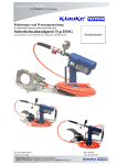
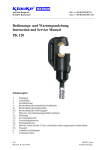
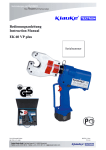
Bedienungsanleitung Instruction Manual Handleiding Manuel d’utilisation EK 120U plus Serialnummer JCS HE.7844_F 2/98 HE7844_F.doc Anzahl der Seiten: 19 Bedienungsanleitung EK 120U plus Seite 2 __________________________________________________________________________________________________________________ Bild/Picture 1 8 3 10 4 6 5 1 2 9 10 7 Bild/Picture 3 Bild/Picture 5 Crimping direction Side b Bild/Picture 4 First crimp Side a Crimping direction First crimp Side b First crimp Bild/Picture 2 Crimping direction Side a Bedienunganleitung EK 120U plus Seite 3 ___________________________________________________________________________________________________________________ Tabelle 1 (siehe Bild 1 Seite 2) Pos.- Bezeichnung Funktion Nr. 1 BedienungsAuslösung des Preßvorgangs schalter 2 Rückstelltaste Taste zum Öffnen der Preßein-sätze im Fehler-, bzw. Notfall 3 Ringöse Vorrichtung zum Sichern des Gerätes und/oder zu Montagezwecken 4 Preßkopf 120 kN U-Preßkopf 5 Gehäuse Ergonomisch geformtes Kunststoffgehäuse 6 Leuchtdioden- Kontrollinstrument zum Feststellen anzeige des Ladezustandes, eines Gerätefehlers und zur Wartungsanzeige. 7 Akku wiederaufladbarer 2,6 Ah NiMH Akku (RA4) 8 Einsatzhalter seitlich herausnehmbarer Block zur Anfnahme der Einsätze 9 Handschutz Bügel zum Schutz der bedienenden Hand, kein Transportgriff! 10 Preßeinsätze Halbschalen Werkzeugeinsätze mit unterschiedlichen Preßprofilen Bedienungsanleitung für das elektro-hydraulische Preßgerät Typ EK 120U plus, Seriennummer ........................ Inhaltsangabe 1 2 3 4 4.1 4.2 4.3 5 5.1 5.2 5.3 5.4 5.5 5.6 6 7 8 Einleitung Aufschriften Gewährleistung Beschreibung des elektro-hydraulischen Preßgerätes Beschreibung der Komponenten Kurzbeschreibung der wesentlichen Leistungsmerkmale des Gerätes Beschreibung der Leuchtdiodenanzeige Hinweise zum bestimmungsgemäßen Gebrauch Bedienung des Gerätes Erläuterung des Anwendungsbereiches Verarbeitungshinweise Wartungshinweise Hinweis zur Verwendung des Akkus und des Ladegeräts Aufbewahrung und Transport des Preßgerätes Verhalten bei Störungen am Preßgerät Außerbetriebnahme/Entsorgung Technische Daten 4.2 Kurzbeschreibung der wesentlichen Leistungsmerkmale des Gerätes Symbole Sicherheitstechnische Hinweise Bitte unbedingt beachten, um Personen- und Umweltschäden zu vermeiden. - Das Gerät besitzt einen automatischen Rücklauf, der den Kolben nach Erreichen des max. Betriebsüberdruckes automatisch in die Ausgangslage zurückfährt. - Das Gerät ist mit einem Nachlaufstop ausgerüstet, der den Vorschub nach Loslassen des Bedienungsschalters (Pos.-Nr. 1) sofort stoppt. - Das Gerät ist mit einer Doppelkolbenpumpe ausgestattet, die durch einen schnellen Vorschub und einen langsamen Arbeitshub gekennzeichnet ist. - Der Preßkopf ist stufenlos 360° um die Längsachse drehbar. Dieses ermöglicht Montagen auch an sehr schlecht zugänglichen Stellen. - Die EK 120U plus ist mit einer Mikroprozessor-Steuerung ausgestattet, die den Motor nach vollendetem Preßvorgang abschaltet, Service Intervalle anzeigt, den Ladezustand des Akkus (Pos.-Nr. 7) angibt, bei Übertemperatur abschaltet und eine Fehlerdiagnose durchführt. Anwendungstechnische Hinweise Bitte unbedingt beachten, um Schäden am Gerät zu vermeiden. 1. Einleitung Vor Inbetriebnahme Ihres Preßgerätes lesen Sie sich die Bedienungsanleitung sorgfältig durch. Benutzen Sie dieses Gerät ausschließlich für den bestimmungsgemäßen Gebrauch. Das Preßgerät darf nur durch eine elektrotechnisch unterwiesene Person bedient werden. Das Mindestalter beträgt 16 Jahre. 4.3 Beschreibung der Leuchtdiodenanzeige Diese Bedienungsanleitung ist während der gesamten Lebensdauer des Gerätes mitzuführen. Die Leuchtdiode (Pos.-Nr. 6) dient in Verbindung mit der Steuerungselektronik zur Information über den Zustand des Akkus (Pos.-Nr. 7) und des Werkzeuges. Im einzelnen leuchtet die Diode in folgenden Fällen: Der Betreiber muß - dem Bediener die Betriebsanleitung zugänglich machen und - sich vergewissern, daß der Bediener sie gelesen und verstanden hat. 2. Signal Aufschriften Auf dem an dem Gehäuse angebrachten Typenschild finden Sie Typbezeichnung, Herkunftsangabe und den Firmennamen. Auf der gegenüberliegenden Seite des Gehäuses befindet sich ein Aufkleber mit einer Kurzdarstellung der preßbaren Querschnitte für Kupfer und Aluminium und die Preßkraft. Die Seriennummer befindet sich auf dem Hydraulikzylinder zwischen dem Gehäuse und dem Preßkopf. Am Preßkopf befindet sich ein Hinweis auf eine mögliche Quetschgefahr bei Preßvorgängen. 3. 1 2 Dauer wenige Sekunden Blinken 20 Sekunden Dauerleuchten 20 Sekunden Blinken (2Hz) 20 Sekunden Blinken (5Hz) 20 Sekunden Leuchten und Blinken Zeitpunkt Bedeutung beim Einsetzen des Durchführung Akkus des Selbsttests Nach dem Akku leer Arbeitsvorgang Nach dem Fehler oder Arbeitsvorgang Wartung fällig Während der Dauer Gerät zu heiß der Übertemperatur Nach dem Wartung fällig Arbeitsvorgang und Akku leer Gewährleistung Die Gewährleistung bei sachgemäßer Bedienung beträgt 12 Monate ab Lieferdatum. 1 4. Beschreibung des elektro-hydraulischen Preßgerätes 4.1. Beschreibung der Komponenten Das elektro-hydraulische Preßgerät mit unserer Typbezeichnung EK 120U plus ist ein handgeführtes Gerät und besteht aus folgenden Komponenten: 2 Anmerkungen: - Blinkt die Leuchtdiode ab einem bestimmten Zeitpunkt immer am Ende eines Arbeitsvorgangs für etwa 20 Sekunden, dann ist eine Wartung fällig. Das Gerät ist baldmöglichst ins Werk einzuschicken. - Beim Auftreten eines Fehlers blinkt die Leuchtdiode gleichfalls am Ende eines Arbeitszykluses. Das Blinken zeigt in diesem Fall das Ansprechen der elektronischen Sicherung an. Eine mögliche Ursache dafür ist der Versuch, einen Zyklus mit einem unzulässig entleerten Akku durchzuführen. Tritt das Blinken auch nach Auswechseln des Akkus weiterhin auf, liegt eine andere Störung vor oder eine Wartung ist fällig. In diesen Fällen ist das Gerät ins Werk einzuschicken. Wird das Gerät zu heiß schaltet sich das Gerät selbständig ab. Nach Absinken der Temperatur ist das Gerät automatisch wieder einsatzbereit. Bedienungsanleitung EK 120U plus Seite 4 __________________________________________________________________________________________________________________ 5. Hinweise zum bestimmungsgemäßen Gebrauch Vor Arbeitsbeginn sind alle aktiven, d.h. stromführenden Teile im Arbeitsumfeld des Monteurs freizuschalten. Ist dieses nicht möglich sind entsprechende Schutzvorkehrungen1 für das Arbeiten in der Nähe von unter Spannung stehenden Teilen zu treffen. Es sollte vor Arbeitsbeginn der Ladezustand des Akkus (Pos.-Nr. 7) überprüft worden sein2. Ein niedriger Ladezustand kann beispielsweise an der Leuchtdiode (Pos.-Nr. 6) durch ein 20 s’iges Aufleuchten am Ende einer Pressung erkannt werden. 5.1. Bedienung des Gerätes Als erstes erfolgt die Auswahl des geeigneten Preßeinsatz (Pos.Nr. 10). Achtung Preßwerkzeug niemals ohne Preßeinsätze betätigen! Anschließend werden die beiden Hälften der Preßeinsätze nacheinander seitlich bis zum Einrasten eingeschoben. Bei Tiefnutpressungen wird der Einsatzhalter (Pos.-Nr. 8) seitlich aus dem Preßkopf entfernt und statt dessen der Tiefnutkäfig eingeschoben. Auf der gegenüberliegenden Seite muß der dazugehörige Tiefnutdorn in den Adapter (Art.-Nr. pp 13) eingesetzt werden. Der Presskopf sollte möglichst vor Beginn des Pressvorganges in die gewünschte Position gedreht werden. Im drucklosen Zustand lässt sich der Presskopf deutlich leichter drehen. Die Betätigung des Bedienungsschalters (Pos.-No. 1) leitet den Preßvorgang ein, der durch das Zusammenfahren der Preßeinsätze gekennzeichnet wird (Bild 2 Stellung A). Dabei befindet sich das auf den Leiter aufgeschobene Verbindungsmaterial bei geschlossenem Preßkopf in dem Preßprofil der stationären Hälfte des Preßeinsatzes3. Ein Preßvorgang ist abgeschlossen, wenn die Preßeinsätze (Pos.Nr. 10) zusammengefahren sind. Der Rücklauf des Kolbens erfolgt automatisch nach Erreichen des max. Betriebsüberdruckes. Anschließend kann ein weiterer Preßvorgang vorgenommen werden oder das Verbindungsmaterial aus dem Preßkopf herausgenommen werden. Achtung Vor Auswechselung der Preßeinsätze unbedingt Akku gegen unbeabsichtigtes Betätigen aus dem Gerät entfernen. Durch Drücken der Rückstelltaste (Pos.-Nr. 2) können im Fehler-, bzw. Notfall die Preßeinsätze in die Ausgangsposition zurückgefahren werden (Bild 2 Stellung C). Achtung Der Preßvorgang kann jederzeit durch Loslassen des Betätigungsschalters unterbrochen werden. 5.2. Erläuterung des Anwendungsbereiches Das Preßgerät verfügt über eine große Anzahl verschiedener Preßeinsätze (Pos.-Nr. 10) zum Verpressen von KlaukeVerbindungsmaterial. Tabelle 2 (siehe Bild 3 auf Seite 2) PreßPreßeinsätze Kennzeichnung bereich außen Preßmm² profil 16-400 RKS und VB CU, QS QS Normalausf. 16-300 Preß-KS und ~ CU, QS, KennVB DIN zahl DIN 46235 46235 DIN 46267 10-300 Aluminium KS AL, QS Kennund VB zahl 25-185 Al-Preß-VB Al, QS KennAldrey zahl 25/4Preßverbinder Al, QS Kenn120/20 DIN 48085 T3 zahl St, QS Kennzahl 10-300 RunddruckRU; sm einsatz QS, sm; QS, sm 16-150 Quetsch-/Stift- CU, QS, QS KS DIN DIN 46234 46234 DIN 46230 10-95 isolierte ISQ, QS QS Quetsch-KS 16-150 Rohr-RKS für F, QS QS feindrähtige Leiter 10-70 C-AbzweigC, QS klemmen 10-150 RKS und VB IS, QS QS isoliert, StiftKS isoliert 2x50- Doppel-PreßDP, QS QS 2x95 RKS 25-240 AEH AE, QS DIN 46228 25-240 AEH für verd. AE, QS feindr. Leiter Oberfläche des Preßeinsatzes gelb chromatiert gelb chromatiert blau verzinkt blau verzinkt blau verzinkt brüniert gelb chromatiert gelb chromatiert gelb chromatiert gelb chromatiert gelb chromatiert gelb chromatiert gelb chromatiert gelb chromatiert gelb chromatiert Abkürzungen: RKS-Rohr-Kabelschuhe, VB-Verbinder, AEHAderendhülsen, QS-Querschnitt Achtung Es dürfen nur die in Tab. 2 genannten Verbindungsmaterialien verpreßt werden. Sollten andere Verbindungsmaterialien verpreßt werden müssen, ist eine Rücksprache mit dem Werk zwingend erforderlich. Die Tiefnutpressung wird gemäß der Französischen Norm C 33090-4 ausgeführt. Achtung Es dürfen keine unter Spannung stehenden Teile verpreßt werden. Bei der EK 120U plus handelt es sich um ein handgeführtes Gerät, das nicht eingespannt werden darf. Es darf nicht für den stationären Einsatz verwendet werden. Das Gerät ist nicht für den Dauerbetrieb geeignet. Es muß nach ca. 30-40 Verpressungen hintereinander eine Pause von ca. 15 min eingelegt werden um das Gerät abzukühlen. Achtung Bei zu intensivem Gebrauch kann es durch Erhitzung zu Schäden am Gerät kommen. Achtung Beim Betrieb von Elektromotoren kann es zur Funkenbildung kommen, durch die feuergefährliche oder explosive Stoffe in Brand gesetzt werden können. 1 Siehe DIN EN 50110-1 siehe Kapitel 5.5 3 Siehe Bild 4 – Montagehinweis für Kabelschuhe und Verbinder 2 Achtung Das elektrohydraulische Preßgerät darf nicht bei starkem Regen oder unter Wasser eingesetzt werden. Bedienungsanleitung EK 120U plus Seite 5 __________________________________________________________________________________________________________________ Tragen Sie das Ladegerät nie am Netzkabel und ziehen Sie es nicht gewaltsam aus der Steckdose heraus. Stecken Sie keine fremden Gegenstände in die Lüftungsgitter des Ladegerätes. 5.3. Verarbeitungshinweise Bitte beachten Sie unbedingt die entsprechenden Montagehinweise1. Das Laden der Akkus darf nur in den vom Hersteller vorgeschriebenen Ladegeräten vorgenommen werden. Achtung Es dürfen auch bei gleicher Kennzahl nur die für das Material vorgesehenen Preßeinsätze verwendet werden. Achtung Stecken Sie den Akku nicht in Ihre Hosentasche oder in Ihre Werkzeugkiste, wenn sich in ihnen leitfähige Teile befinden, wie z.B. Münzen, Schlüssel, Werkzeuge oder andere metallische Teile. 5.4. Wartungshinweise Das Preßgerät ist nach jedem Gebrauch zu reinigen und trocken zu lagern. Sowohl Akku als auch Ladegerät müssen vor Feuchtigkeit und vor Fremdkörpern geschützt werden. Ziehen Sie den Stecker des Ladegerätes nach dem Laden aus der Steckdose heraus. Nehmen Sie das Ladegerät nicht auseinander. Um die Sicherheit und Zuverlässigkeit des Ladegerätes zu gewährleisten sollten Reparatur, Wartung oder Einstellung durch unser Service-Center durchgeführt werden. Das Gerät ist innerhalb der durch die LED angezeigten Serviceintervalle wartungsfrei. Im Rahmen des bestimmungsgemäßen Gebrauchs dürfen vom Kunden nur die Preßeinsätze (Pos.-Nr. 10) gewechselt werden. 5.6. Aufbewahrung und Transport des Preßgerätes Um das Preßgerät vor Beschädigungen zu schützen, muß es nach Gebrauch und nachdem es gesäubert worden ist, in den Transportkoffer gelegt werden, der dann anschließend sicher zu verschließen ist. Achtung Geräteversiegelung nicht beschädigen! Bei Beschädigung der Geräteversiegelung erlischt der Garantieanspruch. 6. Verhalten bei Störungen am Preßgerät 5.5. Hinweis zur Verwendung des Akkus und des Ladegerätes a.) Regelmäßiges Blinken der Leuchtdiodenanzeige (Pos.-Nr. 6) => Akku (Pos.-Nr. 7) austauschen. Leuchtet die Anzeige weiter, muß das Gerät eingeschickt werden. (siehe auch Kap. 4.3) b.) Das Preßwerkzeug verliert Öl. => Das Gerät einschicken. Das Gerät nicht öffnen und die Geräteversiegelung nicht entfernen. c.) Preßwerkzeug erreicht den Enddruck nicht. => Preßvorgang unterbrechen. Rückstelltaste (Pos.-Nr. 2) gedrückt halten und gleichzeitig Bedienungsschalter ca. 10 sec. dauerbetätigen. Wird der Fehler dadurch nicht behoben, muß das Gerät ins Werk eingeschickt werden. Das Ladegerät Typ LG4 ist für 230 V/50-60 Hz ausgelegt. Neue Akkus Typ RA4 müssen vor dem erstmaligen Gebrauch geladen werden. Zur Aufladung des Akkus wird der Stecker des Ladegerätes in die Steckdose und der Akku in das Ladegerät eingesteckt. Die Ladezeit beträgt ca. eine Stunde. Der Ladezustand des Akkus2 wird an der Leuchtdiode am Ladegerät abgelesen. grün: rot: blinken: Akku ist aufgeladen Akku wird gerade geladen. Akku nicht vollständig eingeschoben oder Akku zu heiß, ein akustisches Signal ertönt. Ist der Ladevorgang abgeschlossen wechselt das Ladelicht wieder auf grün, wobei gleichzeitig ein akustisches Signal 5 Sekunden lang ertönt. Es dürfen keine artfremden Akkus weder in der Presse noch im Ladegerät verwendet werden. Laden Sie Ihren Akku auf, sobald die Geschwindigkeit Ihrer Maschine merklich nachläßt, bzw. die Anzeige am Gerät (siehe Kap. 4.3) auf einen leeren Akku hinweist. Laden Sie nicht vorsichtshalber einen teilentladenen Akku nach. Wenn Sie einen Akku aus einem kürzlich betriebenen Gerät oder einen, der längere Zeit in der Sonne lag, laden, kann das Aufladelicht rot blinken. Warten Sie in diesem Fall eine Weile. Das Aufladen beginnt nach Abkühlung des Akku. Blinkt das Aufladelicht abwechselnd rot und grün und wird ein Warnsignal 20 sec. lang abgegeben, ist das Aufladen nicht möglich. Die Pole des Ladegerätes oder die des Akkus sind durch Staub verschmutzt oder der Akku ist verbraucht oder beschädigt. Wollen Sie zwei Akkus nacheinander aufladen, warten Sie 15 min bevor Sie den zweiten Akku laden. Laden Sie den Akku bei einer Raumtemperatur von 10°C bis 40°C. Lassen Sie das Ladegerät nie im Regen oder Schnee liegen. Laden Sie den Akku nicht in Anwesenheit leicht entzündbarer Stoffe oder Gase. 1 Siehe auch Bild 4 auf Seite 2 dieser Bedienunganleitung Der Ladezustand des Akkus kann auch an der LED des Gerätes durch Leuchten am Ende einer Pressung erkannt werden. Siehe Kap. 4.3. 2 7. Außerbetriebnahme/Entsorgung Die Entsorgung der einzelnen Komponenten des Aggregates muß getrennt erfolgen. Dabei muß zuerst das Öl abgelassen werden und an speziellen Abnahmestellen entsorgt werden. Achtung Hydrauliköle stellen eine Gefahr für das Grundwasser dar. Unkontrolliertes Ablassen oder unsachgemäße Entsorgung steht unter Strafe. (Umwelthaftungsgesetz) Anschließend muß der Akku (Pos.-Nr. 7) unter Berücksichtigung der Batterieverordung speziell entsorgt werden. Bei der Entsorgung der restlichen Teile des Aggregates beachten Sie bitte die Umweltstandards der Europäischen Gemeinschaft, respektive der in Ihrem Land geltenden Vorschriften. Wir empfehlen wegen möglicher Umweltverschmutzung die Entsorgung durch zugelassene Fachunternehmen vornehmen zu lassen. Achtung Das Gerät darf nicht als Einheit im Restmüll entsorgt werden, da es auf der Deponie Umweltschäden verursachen kann. Eine kostenfreie Rücknahme des Altgerätes durch den Hersteller kann nicht zugesagt werden. Bedienungsanleitung EK 120U plus Seite 6 __________________________________________________________________________________________________________________ 8. Technische Daten Gewicht des kompl. Gerätes: Preßkraft: Hub: Antriebsmotor: Akkuspannung: Akkukapazität: Akku-Ladezeit: Preßzeit: Pressungen pro Akku: Hydrauliköl: Umgebungstemperatur: Schalldruckpegel: Vibrationen: Instruction Manual ca. 6 kg (inklusive Akku) ca. 120 kN 20 mm Gleichstrom-Permanentfeldmotor 12 V 2,6 Ah (RA4) ca. 1 h [LG 4], bzw. ¼ h [LG5] 6 s bis 13 s (abhängig vom Verbinderquerschnitt) ca. 65 Pressungen (RA4) (Cu 150 mm² DIN 46235) ca. 190 ml "Shell Tellus T 15" -20°C bis +40°C 70 dB (A) in 1m Abstand < 2,5 m/s (gewichteter Effektivwert der Beschleunigung) Anmerkung Diese Bedienungsanleitung kann jederzeit kostenlos unter der Bestell-Nr. HE.7844_F nachbestellt werden. for the electric-hydraulic crimping unit Type EK 120U plus, Serial-No. ........................ Index 1 2 3 4 4.1 4.2 4.3 5 5.1 5.2 5.3 5.4 5.5 5.6 6 7 8 Introduction Labels Warranty Description of the electric-hydraulic crimping unit Description of the components Brief description of the important features of the unit Description of the light diode display Remarks in respect of the determined use Operation of the units Explanation of the application range Mounting instructions Service and Maintenance instructions Remarks on the use of the Battery Cartridge and Charger Storage and transport of the crimping unit. Troubleshooting Putting out of operation/waste disposal Technical data Symbols Safety warnings Please do not disregard these instructions in order to avoid human injuries and environmental damages. Operational warnings Please do not disregard them to avoid damaging the pump unit. 1. Introduction Before starting to use the tool please read the instruction manual carefully. Use this tool exclusively for its determined use. Mounting and assembly of connecting material with the help of this tool must only be performed by specially trained personnel. The minimum age is 16 years. This instruction manual has to be carried along during the entire life span of that tool. The operator has - to guaranty the availability of the instruction manual for the user and - to make sure, that the user has read and understood the instruction manual. 2. Labels On the labels fixed on the housing of the tool you’ll find the type specification name of the manufacturer and the company logo. On the opposite side of the housing you’ll find a label with a brief presentation of the scope of manageable cross-sections for copper and aluminium and the pressing force. The serial number is on the hydraulic cylinder between the housing and the crimping head. On the crimping head you’ll find a warning against possible injuries during the crimp process. 3. Warranty If correct operation is guaranteed our warranty is 12 months from the time of delivery. 4. Description of the electric-hydraulic crimping unit 4.1. Description of the components The electric-hydraulic crimping unit type EK 120U plus is a hand held tool and consists of the following components: Instruction Manual EK 120U plus page 7 __________________________________________________________________________________________________________________ Table 1 (see Picture 1 page 2) Pos.-No. Description Function 1 Trigger switch to start crimping procedure 2 Retract button to open the dies in case of button emergency 3 Ring device to secure the crimping tool and or for assembly. 4 Crimping U-shape crimping head for 120 head kN 5 Housing ergonomically formed plastic housing for perfect handling with a detachable lid 6 Light diode indicator for tool functions and display battery charge control 7 Battery rechargeable NiMH battery cartridge (RA4) 8 die holder opposite support to accommodate the dies 9 Removable guard to protect the operating hand guard hand, not for transportation 10 Dies interchangeable crimping dies 5. Before starting any work on electrical appliances it must be safeguarded that there are no live parts in the immediate assembly area of the user. Is this not possible special precaution measures1 for working near live parts must be provided. Prior to operating the unit the charging level of the battery (Pos.-No. 7) should have been tested2. A low charging level can be detected by the flashing of the LED (Pos.-No. 6) for 20 s at the end of a crimping cycle. 5.1. Operation of the unit Now you have to select the right dies (Pos.-No. 10) for the intended application. Attention Don’t operate the tool without dies. The dies will be inserted sideways into the open crimping head. When performing deep indent crimps the die-holder (Pos.-No. 8) must be replaced against the connector cage of the deep indent crimp set. On the opposite side the indenter must be set into the adapter (KL-part # pp.13). 4.2. Brief description of the important features of the unit The crimping head should be turned into the desired position before starting the crimping cycle. It is significantly easier to turn the crimping head in a pressure free state. - The hydraulic unit incorporates an automatic retraction which returns the piston into its starting position when the maximum operating pressure is reached. - The unit is equipped with a special brake which stops the forward motion of the piston/dies when the trigger (Pos.-No. 1) is released. - The unit is equipped with a double piston pump which is characterised by a rapid approach of the dies (Pos.-No. 10) towards the connector and a slow crimping motion. - The crimping head can be smoothly turned by 360° around the longitudinal axis in order to gain better access to tight corners and other difficult working areas. - The EK 120U plus is equipped with a microprocessor which indicates service intervals, internal checks, low battery charges and switches off at high temperatures. It also shuts off the motor automatically after the crimp is completed. The crimping procedure is initiated by actuating the trigger (Pos.No. 1 & Picture 2 Pos. A). The crimping process is defined by the closing motion of the dies. During that process the connecting material is positioned in the stationary half of the die whereas the moving part of the die is approaching the compression point3. The crimping process is terminated when the crimping force is reached. After having completed the crimp the dies return into the starting position automatically. Afterwards a second crimping cycle can be initiated or the crimping procedure can be terminated. Attention After having terminated the crimping process and prior to changing the dies remove battery to avoid unintended use. 4.3. Description of the light diode display This tool is equipped with a special circuit board incorporating several important features to inform the user about the current status of the unit. The diode (Pos.-No. 6) signals in the following cases: Signal Duration 1 a few seconds of flashing glowing for 20 seconds flashing for 20 seconds (2Hz) flashing for 20 seconds (5Hz) 20 sec. glowing and flashing intermittently 2 When it occures battery insertion after crimp after crimp During high temperature after crimp In case of error or emergency the dies can be returned into the starting position by actuating the retract button (Pos.-No. 2 & Picture 2 Pos. C). Attention The crimping process can be interrupted at any moment by releasing the trigger. What it means self check – O.K. battery discharged return for service unit too hot Remarks in respect of the determined use 5.2. Explanation of the application range The EK 120U plus has a large number of various dies (Pos.-No. 10) available to crimp Klauke connecting material. service required and battery flat 1 Remarks: - Does the diode signal periodically at the end of a working cycle for approx. 20 sec the unit must be returned to an authorised Service Center for Service as soon as possible. - In case of an error the light diode display also signals periodically at the end of a working cycle. The signal indicates in this case the circuit opening by the electronic fuse. A possible reason for that is that a cycle was performed with an incorrectly low battery. If the signal occurs even after changing the battery there must be a different error or a service is due. In these cases the tool must be returned to the manufacturer or an authorised service center. 2 The unit switches off when it gets too hot. It switches on automatically after the unit cooled off. 1 See EN 50110-1 See Chapter 5.5 for more information of the battery and charging unit 3 See picture 4 page 2 2 Instruction Manual EK 120U plus page 8 __________________________________________________________________________________________________________________ Table 2 (see Picture 3, page 2) Crimping Crimping dies range mm² 16-400 TCL and C. Standard Version 16-300 TCL and C. DIN 46235 DIN 46267 10-300 Aluminium CL and C. 25-185 Aluminium C. Aldrey 25/4Full tension C. 120/20 DIN 48085 T3 10-240 sm 35-300 se 16-150 10-95 16-150 4-70 10-150 2x502x95 10-95 25-240 25-240 Pre-rounding dies Terminals DIN 46234 DIN 46230 insulated terminals tub. CL for fine-str. conductors C-clamps pre-insulated tub. CL and connectors double compression CL Oval compression joints WF DIN 46228 WF for comp. fine str. cables Abbreviations: 5.3. Mounting instructions Marking outside profile CU, „QS“ „QS“ CU, QS DIN 46235 AL, „QS“ Al, „QS“ Al, „QS“ ST, „QS“ RU; QS, sm; QS, sm CU, QS DIN 46234 ISQ, QS code # Surface of the dies chrome plated (yellow) chrome plated code # blue zinc code # blue zinc code # blue zinc code # black - chrome plated „QS“ chrome plated „QS“ chrome plated, chrome plated F, QS „QS“ C, QS - IS, QS „QS“ DP, QS „QS“ CU or AL, QS code # AE, QS - AE, QS - Please read the assembly instructions in Chapter 12 of our general catalogue. Attention Even if the code number is identical only those dies should be used which are suitable for the material. Please use the following assembly instructions for cable lugs and connectors: 1. Strip the conductor according to insertion depth (+10% due to the change of length of the crimped sleeve) 2. The Conductor ends must be cleaned with a cloth or brush before the assembly. 3. Insert the conductor fully into the cable lug or connector 4. Pay attention to the crimping directions and use the appropriate dies. The crimping directions3 for cable lugs and connectors is indicated in the illustration below. 5. After crimping, wipe away excess compound forced out of Alcable lugs and connectors. 5.4 Service and maintenance instruction The electric-hydraulic crimping unit is equipped with a sophisticated electronics enabling the user to see when the next service is due. (Pls. read chapter 4.3 for more information) When the next service is due the unit must to be returned to an authorised service center. For every day service the unit has to be cleaned and dried after each use. The battery cartridge (Pos.-No. 7) and the charging unit have to be protected against humidity and dust. chrome plated chrome plated Within the determined use of the tool only the dies (Pos.-No. 10) are permitted to be changed by the customers. chrome plated chrome plated chrome plated chrome plated Attention Do not damage the seals of the tool. If the seals are damaged the warranty is invalidated. 5.5 Remarks on the use of the battery cartridge and charging unit. The charging unit type LG4 is run with a nominal voltage of 230 V and a frequency of 50-60 Hz. New batteries must be charged prior to use. To charge the battery cartridge (Pos.-No. 7) the power plug of the charging unit has to be plugged into the power supply and the battery cartridge has to be pushed into the charging unit. The charging time is one hour. The charging level of the battery cartridge can be checked by a LED4. TCL-Tubular cable lugs, C-Connectors, WFWire Ferrules, QS-Cross-section Attention Do only crimp those connecting materials mentioned in Tab. 2 If different conducting materials have to be crimped, please contact the manufacturer. green red flashing The deep indent crimping is performed according to the French Standard C 33-090-4. Is the battery plugged in correctly the LED changes from green to red and the charging procedure starts. When the charging procedure is terminated the LED changes again to green. Simultaneously a signal occurs for 5 seconds. Attention Do not crimp on live cables or conductors The EK 120U plus is a hand held tool and it is not supposed to be restrained in a vise. It is not allowed to use the tool in a stationary application. No other battery cartridges e.g. dry batteries or car batteries etc. are permitted to be used neither in the tool nor in the charging unit. The tool is not designed for continued crimping operations. After a sequence of approximately 30-40 completed crimps you have to make a break of 15 min. to give the tool time to cool down. As soon as the speed of the machine decreases noticeably the battery must be recharged. Do not recharge a partially empty battery as a precaution. Attention Too intensive use can cause heat damages for the tool If charging a battery which has currently been used or which was laying in the sun for a longer period of time the LED might flash red. In this case wait for a while. The charging procedure starts after the battery cooled down. Attention During the operation of electric engines sparks can occur which might ignite highly inflammable or explosive liquids and materials 3 Attention Electric-hydraulic crimping tools should not be operated in pouring rain or under water. battery cartridge is charged Battery cartridge is empty and is just being charged battery cartridge is not pushed in properly or too hot, a sound signal occurs See Picture 4 on Page 2 The charging level of the battery can also be verified by the LED of the tool at the end of a crimping cycle. See chapter 4.3 for further information. 4 Instruction Manual EK 120U plus page 9 __________________________________________________________________________________________________________________ Does the LED flash red and green and does an audible tone occur for 20 seconds it is not possible to charge that battery. The poles of the battery or the charging unit are dirty or the battery is low or damaged. If you want to charge two batteries in a row wait for 15 min before you charge the second battery. Avoid great fluctuating temperatures under 0°C and above 40°C. Through these fluctuations damages may result for the battery cartridge as well as for the charging unit. The best operation temperature is between 15-25 °C. 8. Technical Data Weight of the complete tool: Crimping force: Stroke: Driving motor: Battery voltage: Battery capacity Charging time: Hydraulic oil: Environmental temperature: Sound level: Vibrations: approx. 5,95 kg (incl. battery) approx. 120 kN 20 mm direct-current permanent field motor 12 V 2,6 Ah (RA4) approx. 1 h [LG4], ¼ h with Quickcharger [LG5] approx. 6 s to 13 s (depending on the connector size) approx. 65 crimps (Cu 150 mm² DIN 46235) approx. 190 ml "Shell Tellus T 15" -20°C to –40°C 70 dB (A) in 1m distance < 2,5 m/s² Dimensions: See Picture 2 Crimping time: Do not leave or operate the charging unit in rain or snow. Do not charge the battery near lightly inflammable materials or gases. Do not use the cord to transport the charging unit or to pull the plug out of a wall socket with force. Do not insert strange parts into the ducts of the charging unit. The charging of the batteries must only be done with charging units supplied by the manufacturer. Attention Do not place the battery in your pocket or in your toolbox if there are any conductive materials in it such as coins, keys, tools or other metallic parts. Pull the plug of the charging unit after charging. Do not disassemble the charging unit or battery. In order to safeguard a safe and proper performance of the charging unit the repair and service of the unit should be made through our Service Center. 5.6 Storage and transport of the crimping tool In order to protect the tool against damages it has to be cleaned carefully after each use and be put into the transportation case which has to be closed safely. 6. Troubleshooting a.) Flashing of the light diode display (Pos.-No. 6) => See chapter 4.3 for more information about the special functions of the tool. b.) The tool loses oil. => Return the tool to the manufacturer. Do not open the tool and damage the seals of the tool. c.) The crimping tool does not reach the final operating pressure. => Stop the crimping process. Press the retract button (Pos.-No. 2) and the operating switch continuously and simultaneously for about 10 sec. Is the malfunction not be eliminated by this attempt the tool has to be returned to the manufacturer. 7. Putting out of operation/waste disposal The disposal of the various components of the tool has to be treated separately. First you have to dispose of the oil at special delivery points. Attention Hydraulic oils represent a danger for the groundwater. Uncontrolled draining of or improper disposal is under penalty. (environmental liability law) Next, the battery cartridge (Pos.-No. 7) has to be specially disposed of according to the EEC Battery Guideline. For the disposal of the remaining parts please reference the EC environmental guideline. Because of possible environmental damages we recommend to dispose of the tool by professional companies. Attention Do not dispose of the unit in your residential waste because it will finally end up on the waste dump which would be hazardous for the environment. A return of the old tool free of charge to the manufacturer cannot be granted. Crimp per battery: Note Additional instruction manuals are available free of charge. The part # is HE.7844_F. Handleiding EK 120U plus pagina 10 __________________________________________________________________________________________________________________ Handleiding voor de accu persmachine type EK 120U plus, serienummer ........................ Inhoud Tabel 1 (zie afbeelding 1) Pos. Omschrijving 1 Bedieningsschakelaar 2 Teruglooptoets 1. Inleiding 2. Labels 3. Garantie 4. Beschrijving van het elektrisch - hydraulisch persapparaat 4.1. Beschrijving van de componenten 4.2. Korte beschrijving van de belangrijkste mogelijkheden van het apparaat 4.3. Beschrijving van de lichtdiode - indicatie 5. Aanwijzingen voor het beoogd gebruik 5.1. Bediening van het apparaat 5.2. Verklaring van het toepassingsgebied 5.3. Verwerkingsaanwijzingen 5.4. Onderhoudsaanwijzingen 5.5. Aanwijzing bij het gebruik van de accu en het laadapparaat 5.6. Opbergen en transport van het persapparaat 6. Wat te doen bij storingen van het persapparaat 7. Buiten werking stellen / Weggooien 8. Technische gegevens Veiligheidstechnische aanwijzingen Absoluut opvolgen om schade aan personen en milieu te voorkomen. Toepassingstechnische aanwijzingen Absoluut opvolgen om schade aan personen en milieu te voorkomen. Inleiding Lees voordat u uw persapparaat in gebruik neemt de handleiding zorgvuldig door. Gebruik dit apparaat uitsluitend voor het doel waarvoor het gemaakt is en volg daarbij de algemene veiligheidsvoorschriften en de voorschriften ter voorkoming van ongevallen op. Gebruik het apparaat uitsluitend voor het beoogde doel. Deze handleiding moet tijdens de totale levensduur van het apparaat zorgvuldig bewaard worden. De gebruiker moet - zorgen dat de handleiding beschikbaar is voor de operator en - er zich van overtuigen dat de operator deze gelezen en begrepen heeft 2. Garantie De garantie bij deskundig gebruik en regelmatig onderhoud van het apparaat bedraagt 12 maanden vanaf de leverdatum. 4. 6 Lichtdiode - indicatie 7 Accu 8 9 Handbescherming 10 Matrijzen 11 Accu borgveer - Het apparaat bezit een automatische terugloop die de aandrijfrollen na het bereiken van de max. bedrijfsdruk automatisch naar de uitgangspositie terugbrengt. - Het apparaat heeft een naloopstop die de voortstuwende beweging direct stopt nadat de bedieningsschakelaar is losgelaten (pos.nr. 1). - Het apparaat heeft een dubbele zuigerpomp die door een snelle voortstuwende beweging en een langzame werkslag gekenmerkt wordt. - De persbekhouder (pos. 4) is traploos 360° om de lengteas draaibaar. Hierdoor is ook montage op zeer slecht toegankelijke plaatsen mogelijk. - De EK 120U plus heeft een microprocessor besturing die de motor na het persen uitschakelt, service - intervallen aangeeft, de laadstand van de accu (pos.nr. 7) aangeeft en een foutdiagnose uitvoert. 4.3. Beschrijving van de lichtdiode-indicatie De lichtdiode (pos.-nr. 6) dient in combinatie met de besturingselektronica voor het verstrekken van informatie over de toestand van de accu (pos.-nr. 7) en van het werktuig. Concreet brandt de diode in de volgende gevallen: Signaal Labels Op het op de behuizing bevestigde typeplaatje vindt u de typeaanduiding, informatie over de fabrikant en de firmanaam. Op de tegenoverliggende zijde van de behuizing bevindt zich een sticker met de technische gegevens en het serienummer. Op de persbekhouder bevindt zich een waarschuwing tegen mogelijk pletgevaar bij het persen. 3. Ophangoog Perskop Behuizing Toets voor het teruglopen van de zuigerstang bij storingen en / of noodgevallen. Ophangbevestigingspunt 120kN U - kop Ergonomisch uitgevoerde kunststof behuizing met afneembare deksel Controle instrument voor het vaststellen van de laadstand en Verdere apparaat functies. Oplaadbare 2,6 Ah NiMH accu (RA4) Beugel ter bescherming van de bedienende hand Halfschaalvormige, onderling uitwisselbare matrijzen Veer om de accu vast te zetten 4.2. Korte beschrijving van de belangrijkste mogelijkheden van het apparaat Symbolen 1. 3 4 5 Functie Starten van het persen Beschrijving van het elektrisch - hydraulisch persapparaat 4.1. Beschrijving van de componenten Het elektrisch - hydraulisch persapparaat met onze typeaanduiding EK 120U plus is een handbediend apparaat en bestaat uit de volgende componenten: 1 2 Duur enkele seconden knipperen 20 seconden continulicht 20 seconden knipperen (2Hz) 20 seconden knipperen (5Hz) 20 seconden branden en knipperen Tijdstip bij het inleggen van de accu na het werken Betekenis bezig met de zelftest accu leeg na het werken fout of onderhoud noodzakelijk apparaat te heet tijdens de duur van de overtemperatuur na het werken onderhoud noodzakelijk en accu leeg 1 Opmerkingen: - Als de lichtdiode vanaf een bepaald moment altijd op het einde van een werkcyclus gedurende ongeveer 20 seconden knippert, is een onderhoud noodzakelijk. Het apparaat moet zo snel mogelijk naar de fabriek worden gestuurd. - De lichtdiode knippert eveneens op het einde van een werkcyclus wanneer een fout is opgetreden. Het knipperen geeft in dit geval aan dat de elektronische zekering is aangesproken. Een mogelijke oorzaak hiervoor is de poging een cyclus uit te voeren met een ontoelaatbaar leeggemaakt accu. Als het knipperen zelfs na verwisseling van de accu blijft duren, is een andere storing aanwezig of is een onderhoud noodzakelijk. In deze gevallen moet het apparaat terug naar de fabriek worden gestuurd. 2 Als het apparaat te heet wordt, schakelt het zich automatisch uit. Na het dalen van de temperatuur is het apparaat automatisch weer gebruiksklaar. Handleiding EK 120U plus pagina 11 __________________________________________________________________________________________________________________ 5. Aanwijzingen voor het beoogde gebruik Voor met het werk te beginnen moeten alle actieve, d.w.z. stroomgeleidende onderdelen in het werkgebied van de monteur vrijgeschakeld worden. Als dat niet mogelijk is, moeten de betreffende beschermmaatregelen1 voor het werken in de buurt van onder spanning staande onderdelen genomen worden. 5.1. Bediening van het apparaat Tabel 2 (zie afb. 3 op pagina 2) PersMatrijzen Aanduiding bereik buiten Persmm2 profiel 16-400 16-300 Dan moet de geschikte matrijs (pos.nr. 10) gekozen worden. Let op Persgereedschap nooit zonder matrijs gebruiken! De twee halve schaaldelen van de matrijs worden één voor één vanaf de zijkant ingeschoven tot ze vastklikken. Voor met het werk te beginnen moet de laadstand van de accu (pos.nr. 7) gecontroleerd worden2. Een lage laadstand kan bijvoorbeeld aan het 20 seconden lang oplichten van de lichtdiode (pos.nr. 6) aan het einde van het persen vastgesteld worden. Het gebruik van de bedieningsschakelaar (pos.nr. 1) start het persen, dat door het samenkomen van de persmatrijzen gekenmerkt wordt (afb. 2 stand A). Daarbij bevindt zich het op de geleider geschoven verbindingsmateriaal bij gesloten persbekhouder in het persprofiel van de stationaire helft van de matrijs3. Het persen is afgesloten als de matrijzen samengevoegd zijn (pos.nr. 10). De terugloop van de zuiger geschiedt automatisch nadat de maximale bedrijfsdruk is bereikt. Daarna kan nog een keer geperst worden of door het openen van de trekstaaf (pos.nr. 3) het verbindingsmateriaal uit de persbekhouder genomen worden. Let op Voor het verwisselen van de matrijzen absoluut tegen per ongeluk gebruiken beveiligen. Door op de resettoets (pos.nr. 2) te drukken kunnen bij storingen of noodgevallen de matrijzen in de uitgangspositie teruggezet worden (afb. 2 stand B). Let op Het persen kan te allen tijde onderbroken worden door de bedieningsschakelaar los te laten. 10-300 25-185 25/4120/20 Het persapparaat beschikt over een groot aantal verschillende matrijzen (pos.nr. 10) voor het persen van Klaukeverbindingsmateriaal. CU, QS QS CU, QS DIN 46235 AL, QS AL, QS Kengetal Kengetal Kengetal blauw verzinkt blauw verzinkt AL, QS Kengetal blauw verzinkt St, QS Kengetal gebruind RU: QS, ms QS, sm CU, QS, DIN 46234 ISQ, QS - geel gechromatiseerd geel gechromatiseerd 10-300 sm Ronde persmatrijs 16-150 Plet-/stift-KS DIN 46234/ DIN 46230 10-95 Geïso-leerde plet-KS 16-150 Buis-RKS voor fijndradige L. C-aftakklemmen F, QS QS C, QS - RKS en VB geïsoleerd, stift-KS geïsoleerd Dubbele persRKS IS, QS QS DP, QS QS AE, QS - 10-70 10-150 2x502x95 25-240 Afkortingen: 5.2. Verklaring van de toepassingsgebieden RKS en VB normale uitvoering Pers-KS en – VB DIN 46235/ DIN 46267 aluminium KS en VB aluminium persverbinder Aldrey Persverbinder DIN 48085 T3 AEH DIN 46228 Oppervlakte van de matrijs QS QS geel gechromatiseerd geel gechromatiseerd geel gechromatiseerd geel gechromatiseerd geel gechromatiseerd geel gechromatiseerd geel gechromatiseerd geel gechromatiseerd RKS = buiskabelschoen, VB = verbinder, AEH = adereindhulzem, QS = diameter, L- geleider Let op Alleen de in tab.2 genoemde verbindingsmaterialen mogen geperst worden. Als andere verbindingsmaterialen geperst moeten worden, moet overlegd worden met de fabriek. Let op Er mogen geen onder spanning staande onderdelen geperst worden. Bij de EK 120U plus gaat het om een handbediend apparaat dat niet ingespannen mag worden. Het mag niet stationair gebruikt worden. Het apparaat is niet voor permanent gebruik bestemd. Na ca. 30-40 persingen achter elkaar moet een pauze van ca. 15 min ingelast worden om het apparaat te laten afkoelen. Let op Bij een te intensief gebruik kunnen er door verhitting schaden aan het apparaat ontstaan. 1 Zie DIN EN 50110-1 Zie hoofdstuk 5.5 3 Zie afbeelding 4 – montage-aanwijzingen voor kabelschoentjes en verbinders 2 Let op Bij gebruik van elektromotoren kunnen vonken ontstaan waardoor vuurgevaarlijke of explosieve stoffen in brand kunnen vliegen. Handleiding EK 120U plus pagina 12 __________________________________________________________________________________________________________________ Vermijd sterke temperatuurschommelingen onder 0°C en boven 40°C. Daardoor kunnen beschadigingen aan de accu en aan het persapparaat optreden. De optimale bedrijfstemperatuur ligt tussen 15 en 25 °C. Laat het laadapparaat nooit in de regen of sneeuw liggen. Laadt de accu niet op in de buurt van licht ontplofbare stoffen of gassen. Let op Het elektro hydraulische persapparaat mag niet bij sterke regen of onder water gebruikt worden. 5.3 Verwerkingsaanwijzingen Volg absoluut de in de catalogus in hoofdstuk 12 genoemde montage-aanwijzingen 4 op. Draag het laadapparaat nooit aan het netsnoer en trek het nooit met geweld uit de wandcontactdoos. Stop geen vreemde voorwerpen in de ventilatieroosters van het laadapparaat. Let op Er mogen bij gelijk kengetal alleen de voor het materiaal voorziene matrijzen gebruikt worden. Het opladen van de accu mag alleen m.b.v. de door de fabrikant voorgeschreven laadapparaten plaatsvinden. 5.4. Onderhoudsaanwijzingen Let op! Stop de accu niet in uw broekzak of in uw gereedschapskist als zich daar geleidende voorwerpen bevinden zoals bijv. munten, sleutels, gereedschap of andere metalen voorwerpen. Het persapparaat moet na elk gebruik schoongemaakt worden en droog opgeborgen worden. Zowel de accu als het laadapparaat moeten tegen vocht en vreemde voorwerpen beschermd worden. Het apparaat is onderhoudsvrij, alleen de boutverbindingen moeten licht ingeolied worden. Trek de steker van het laadapparaat na het opladen uit de wandcontactdoos. Haal het laadapparaat niet uit elkaar. In het kader van het beoogde gebruik mogen door de klant alleen de matrijzen (pos.nr. 10) vervangen worden. Om de veiligheid en betrouwbaarheid van het laadapparaat te garanderen moeten reparaties, onderhoud of instellingen door het Klauke Service Center uitgevoerd worden. Let op Apparaatverzegeling niet beschadigen! 5.6. Opbergen en transport van het persapparaat Bij beschadiging van de apparaatverzegeling vervalt de garantie. Om het persapparaat tegen beschadigingen te beschermen moet het na gebruik en nadat het schoongemaakt is in de transportkoffer gelegd worden die daarna afgesloten wordt. 5.5. Aanwijzing voor het gebruik van de accu en het laadapparaat Het laadapparaat is gemaakt voor wisselspanning van 230 V met een frequentie van 50 Hz. Nieuwe accu's moeten voor het gebruik opgeladen worden. Om de accu op te laden wordt de steker van het laadapparaat in de wandcontactdoos en de accu in het laadapparaat gestoken. De laadtijd bedraagt ca. één uur. De laadstand van de accu kan op een lichtdiode op het laadapparaat afgelezen worden. groen: rood: knipperen: In deze koffer zit nog een reserve-accu (optioneel), het laadapparaat, en de gebruikshandleiding. 6. a.) Regelmatig knipperen van de lichtdiode-indicatie (pos. 6) => accu (pos. 7) vervangen. Als de indicatie blijft branden moet het apparaat opgestuurd worden (zie ook hoofdstuk 4.3) b.) Het persapparaat verliest olie. => Het apparaat opsturen. Open het apparaat niet en verwijder de garantieverzegeling niet. c.) Motor schakelt niet uit en er volgt geen automatische terugloop. => Persen onderbreken. Terugsteltoets (pos. 2) ingedrukt houden en tegelijkertijd bedieningsschakelaar ca. 10 seconden ingedrukt houden. Als de storing daarmee niet verholpen wordt, moet het apparaat naar het Klauke Service Center gestuurd worden. accu is opgeladen accu is leeg en wordt opgeladen. accu zit er verkeerd ingeschoven of is te heet, er klinkt een akoestisch signaal. Schuif de accu zo in het apparaat dat de plus- en minpolen op de accu overeenkomen met die op het laadapparaat. Als de accu correct is aangesloten, gaat het oplaadlampje van groen op rood over en begint het opladen. Als het opladen gereed is wisselt het oplaadlampje weer naar groen, waarbij tegelijkertijd 5 seconden lang een pieptoon klinkt. Er mogen geen andere types accu gebruikt worden, bijv. droge accu's of autoaccu's, niet in het persapparaat en niet in het laadapparaat. Laad de accu op zodra de snelheid van de machine merkbaar minder wordt. Laad niet uit voorzorg een gedeeltelijk ontladen accu op. Als u een accu oplaadt uit een net gebruikt apparaat of één die lang in de zon heeft gelegen, kan het oplaadlampje rood knipperen. Wacht in dat geval een poosje. Het opladen begint als de accu afgekoeld is. 7. Buiten bedrijf stellen/Weggooien Het weggooien van de diverse componenten van het apparaat moet gescheiden gebeuren. Daarbij moet eerst de olie afgetapt worden en op een speciaal inzamelpunt ingeleverd worden. Let op! Hydraulische oliën zijn gevaarlijk voor het grondwater. Ongecontroleerd aftappen of ondeskundig weggooien is strafbaar. Vervolgens moet de accu afgegeven worden op één van de daarvoor bestemde inzamelpunten. Als het oplaadlampje afwisselend rood en groen knippert en er klinkt 20 seconden lang een pieptoon, dan kan er niet opgeladen worden. Houd u zich bij het weggooien van de resterende onderdelen van het apparaat aan de EG - milieurichtlijnen. De polen van het laadapparaat of die van de accu zijn vuil of de accu is op of beschadigd. Wij raden aan wegens mogelijke milieuvervuiling het weggooien uit te laten voeren door daarin gespecialiseerde bedrijven. Het oude apparaat kan niet kosteloos door de fabrikant teruggenomen worden. Als u twee accu’s na elkaar wilt opladen, wacht u 15 minuten voordat u de tweede accu gaat opladen. 4 Wat te doen bij storingen van het persapparaat Zie ook afb. 4 op pagina 2 van deze handleiding Handleiding EK 120U plus pagina 13 __________________________________________________________________________________________________________________ 8. Mode d’emploi Technische gegevens Gewicht van het complete apparaat incl. accu: Perskracht: Aandrijfmotor: Accucapaciteit: Accuspanning: Accu laadtijd: Perstijd: Persingen per accu: Hydraulische olie: Omgevingstemperatuur: Geluidsniveau: Vibraties: Maten: ca. 5,95 kg ca. 120 kN Gelijkstroom-permanentveldmotor 2,6 Ah (RA4) 12 V ca. 1 uur (LG4), resp. 0,25 uur met snellader (LG5) 6 s tot 13 s (afhankelijk van de connectorgrootte) ca. 65 persingen (bij Cu 150 mm² DIN 46235) ca. 190 ml "Shell Tellus T 15" -20°C tot +40°C 70 dB (A) op 1 m afstand < 2,5 m/s² (gewogen effectieve waarde van de versnelling) Zie afb. 2 Opmerking Deze handleiding kan kosteloos onder bestelnummer HE.7844_F nabesteld worden. De la sertisseuse électro portative à accumulateur EK120U plus, Numéro ........................ Sommaire 1. 2. 3. 4. 4.1 4.2 4.3 5. 5.1 5.2 5.3 5.4 5.5 5.6 6. 7. 8. Introduction Etiquette informative Garantie Description de la sertisseuse électro-hydraulique Description des composants Description suscite des principales caractéristiques de l’appareil Description de l’affichage LED Instructions pour une utilisation conforme Utilisation de l’appareil Description du domaine d’application Instructions pour l’utilisation Instructions pour la maintenance Instructions pour l’utilisation de l’accumulateur et du chargeur Stockage et transport de la sertisseuse Marche à suivre en cas de panne Mise hors service, mise au rebut Caractéristiques techniques Symboles Instructions techniques de sécurité à respecter impérativement pour la sécurité des personnes et la protection de l’environnement. Instructions techniques d’utilisation à respecter impérativement pour éviter des dommages à l’appareil. 1. Introduction Lire attentivement le mode d’emploi avant la mise en service de la sertisseuse. N’utilisez cet appareil qu’exclusivement pour l’usage prévu, en respectant les instructions relatives à la sécurité et à la prévention des accidents du travail. Ce mode d’emploi doit accompagner l’appareil pendant toute sa durée d’utilisation. L’exploitant doit: - mettre le mode d’emploi à la disposition de l’utilisateur, et - s’assurer que celui-ci ait lu et bien compris sont contenu. 2. Etiquette informatives La plaquette d’identification située sur le corps de l’appareil indique le type de l’appareil, son origine et le nom du fabricant. Sur le coté opposé du corps une étiquette indique le numéro de série et les caractéristiques techniques et le numéro de série. La tête de sertissage comporte une étiquette signalant le danger possible de pincement pendant l’opération de sertissage. 3. Garantie La garantie est de 12 mois à compter de la date de livraison. Elle n’est valable que dans le cadre d’une utilisation conforme et sous condition du respect des contrôles périodiques 4. Description de la sertisseuse électro-hydraulique 4.1 Description des composants La sertisseuse électro-hydraulique type EK120U-plus est un appareil manuel qui se compose des éléments suivants Manuel d’utilisation EK120U plus Page 14 __________________________________________________________________________________________________________________ Tableau 1 (voir figure 1) Pos - Désignation Nr Commutateur 1 de marche Touche de 2 retour Porte matrice 3 SM120 Tête de 4 sertissage Corps de 5 l’appareil 6 Afficheur LED 7 Accumulateur 8 9 Protection manuelle Matrices de sertissage 10 5. Instructions pour une utilisation conforme Fonction Déclenchement du sertissage Avant l’utilisation de la sertisseuse, s’assurer qu’aucun composant actif sous tension n’est accessible. Si tel devait être le cas, des précaution particulière devront être prises. Retour du piston en position initiale en cas de défaut ou d’urgence Maintenir la ½ matrice en position 5.1 Utilisation de l’appareil Tête de sertissage en U - 120kN Corps de la sertisseuse, de forme ergonomique avec cache réservoir Afficheur de contrôle de l’état de charge et autres fonctions de l’appareil Accumulateur rechargeable au 2,6 Ah NiMH (RA4) Arceau de protection de la main de l’opérateur Matrices permettant d’effectuer le sertissage (interchangeables en fonction de la section et du type de produit à sertir Prendre la matrice correspondant à la section et au produit à sertir (pos. 10) (voir tableau 2) Attention Ne jamais faire fonctionner la sertisseuse sans les 2 matrices Mettre en place les 2 matrices jusqu’au clic qui assure le maintien et le positionnement correct. Pour effectuer le sertissage par P.P.E (poinçonnage profond étagé, suivant la norme E.D.F HN68.S.90), il faut monter d’abord le poinçon correspondant (0E - 1E - 2E - 4E) sur le porte poinçon PP120 et monter le tout sur le piston de la sertisseuse, puis retire le support matrice SM120 (pos.3) et mettre en place une matrice avec sommier incorporé (MC0E - MC1E - MC2E MC4E - MJ0E - MJ1E - MJ2E - MJ4E etc...) 4.2 Description succincte des principales caractéristiques de Contrôler avant utilisation l’état de charge de l’accumulateur. Un état de l’appareil charge faible peut être reconnu lorsque la LED reste par exemple allumée pendant 20 secondes après un essais de sertissage (voir chapitre - L’appareil possède une fonction de retour automatique, qui 4.3). ramène automatiquement la matrice en position initiale après que les sertissage ait atteint la pression maxi requise. On obtient le déclenchement d’un cycle de sertissage en maintenant la - L’appareil est équipé d’un dispositif d’arrêt immédiat qui stoppe pression sur le bouton de commande (pos. 1- voir: vue 2 -A). instantanément l’avance dès que le bouton de sertissage est relâché (pos. 1) Le processus de sertissage se caractérise par l’avancée de la matrice ou - L’appareil est équipé d’une pompe à double piston, caractérisée du poinçon vers la matrice fixe. Le sertissage est terminé lorsque le par une vitesse d’approche rapide et d’une course lente de moteur s’arrête et que le retour de la matrice ou du poinçon mobile dans sertissage. sa position initiale se fait automatiquement. - La tête de sertissage (pos. 4) peut être tournée de 360° en continu autour de son axe. Ceci permet le sertissage dans des endroits Attention difficilement accessibles. Avant de changer de matrice, ......... . - La sertisseuse EK120U-plus est équipé d’une commande à microprocesseur qui coupe le moteur lorsque le sertissage est complètement terminé, qui indique la périodicité de la En cas de défaut ou d’urgence, le retour de la matrice ou du poinçon maintenance, ainsi que l’état de charge de l’accumulateur (pos. 7) mobile dans sa position initiale peut se faire en appuyant sur le bouton et qui effectue un diagnostic des défauts. de rappel (pos. 2 - voir: vue 2 - C). 4.3 Description de l’afficheur LED En liaison avec la commande électronique, la diode électroluminescente (no. 6) a pour fonction d’informer sur l’état de l’accu (no. 7) et sur celui de l’outil. La diode s’allume dans les cas spécifiques suivants : 1 Signal Durée Moment Signification Mise en place de l’accu Après l’opération de sertissage Exécution de l’autotest Accu est vide 1 Clignote pendant quelques secondes Signal lumineux continu pendant 20 secondes Clignote pendant 20 secondes (2Hz) Après l’opération de sertissage 2 Clignote pendant 20 secondes (5Hz) Erreur ou date d’entretien atteinte Appareil trop chaud Pendant la durée de la surtempérature Signal lumineux et Après l’opération clignotant pendant de sertissage 20 secondes Attention Le processus de sertissage peut être interrompu à tout instant en relâchant la pression exercée sur le bouton de commande. 5.2 Description du domaine d’application La sertisseuse peut être utilisée dans un grand nombre d’application de sertissage de raccords et cosses KLAUKE, ainsi que pour tout type de raccords disponibles sur le marché mondial (voir tableau 2). Date d’entretien atteinte et accu vide Remarques: - - Si, à partir d’un moment donné, la diode électroluminescente clignote toujours pendant environ 20 secondes à la fin d’une opération de sertissage, il faut effectuer l’entretien de l’appareil. L’appareil doit être renvoyé le plus vite possible à l’usine. En cas de perturbation, la diode électroluminescente clignote également à la fin d’une opération de sertissage. Dans ce cas, le clignotement indique la réaction du système de sécurité électronique. Ceci peut être dû au fait que vous avez essayé d’exécuter un cycle avec un accu déjà trop déchargé. Si le clignotement se présente encore après le remplacement de l’accu, il faut renvoyer l’appareil à l’usine. 2 Lorsque l’appareil est en surchauffe, il s’arrête automatiquement. Une fois que la température a baissé, il revient automatiquement en position de fonctionnement. Manuel d’utilisation EK120U plus Page 15 __________________________________________________________________________________________________________________ Tableau 2 Référ- Cosses et ence manchons cuivre NFC 20-130 HNF 13/10 HNF 13/16 HNF 13/25 HNF1 3/35 HNF1 3/50 HNF1 3/70 HNF1 3/95 HNF1 3/120 HNF1 3/150 HNF1 3/185 HNF1 3/240 HNF1 3/300 Référence 5.3 Instructions pour l’utilisation Raccords en C1 (mm²) 10 (mm²) C6 16 25 C25 35 50 70 C16 95 120 150 C25-C35C50 185 240 300 HE13/140 Cosses alucuivre indust. à fût court (mm²) 35 -50 HE13/173 70-95-120 HE13/235 150-185-240 HE13/260 300 Cosses alu-cuivre Matrice MC0E MC1E MC2E MC4A HN.68.S.90 Poinçon OE 1E 2E 4E Observations: matrices couleur bichromatage jaune bichromatage jaune bichromatage jaune bichromatage jaune bichromatage jaune bichromatage jaune bichromatage jaune bichromatage jaune bichromatage jaune bichromatage jaune bichromatage jaune bichromatage jaune Observations: matrices couleur bichromatage blanc bichromatage blanc bichromatage blanc bichromatage blanc Manchon aluminium Matrice MJ0E MJ1E MJ2E MJ4E Veiller à utiliser l’appareil les matrices adaptées au produit à sertir, et en cas de doute prendre contact avec la fabricant. empreinte hexagonale marquée 10 hexagonale marquée 16 hexagonale marquée 25 hexagonale marquée 35 hexagonale marquée 50 hexagonale marquée 70 hexagonale marquée 95 hexagonale marquée 120 hexagonale marquée 150 hexagonale marquée 185 hexagonale marquée 240 hexagonale marquée 300 empreinte hexagonale double 2x9mm hexagonale double 2x9mm hexagonale double 2x9mm hexagonale double 2x9mm HN.68.S.90 Sections Poinçon 0E 1E 2E 4E (mm²) 16-25-35 50-70-95 120-150 185-240 Nota: Manchons alu-cuivre: se référer au catalogue page 4.3, ou nous consulter Autres matrices: nous consulter Attention Ne jamais sertir des composants sous tension. L’appareil n’est pas destiné à un service continu. Après environ 50 sertissages successifs, il est nécessaire de marquer une courte pause d’au moins 15 minutes afin que l’appareil puisse refroidir. Attention Une utilisation intensive peut provoquer des dommages à l’appareil par suite de surchauffe. Veuillez vous référer à la vue 4 pour effectuer vos sertissages dans les meilleures conditions. 5.4 Instructions pour la maintenance Effectuez soigneusement la maintenance de votre appareil pour lui assurer un fonctionnement sûr et satisfaisant. L’entretien est condition essentielle de l’obtention de sertissages de qualité. Pour garantir ce résultat l’appareil doit faire l’objet d’une maintenance et d’un entretien régulier. Veuillez tenir compte des points suivants: 1. 2. 3. La sertisseuse doit être nettoyée après chaque utilisation et doit être remise dans un coffret sec. L’accumulateur ainsi que le chargeur doivent également être éloignés de toute humidité. La sertisseuse ne nécessite pas d’entretien particulier. Cependant les maintenances habituelles doivent être respectés. Attention Ne pas ouvrir l’appareil sous peine de perdre la garantie 5.5 Instructions pour l’utilisation de l’accumulateur et du chargeur Le chargeur doit être alimenté en 220v /50-60Hz. Les accumulateurs neufs doivent être chargés avant leur mise en service. Pour charger les accumulateurs, introduire la fiche du chargeur dans la prise de courant et placer l’accumulateur dans le chargeur. Le temps de charge est d’environ une heure. L’état de charge est indiqué par une LED disposée dans le chargeur. vert: l’accumulateur est chargé rouge: l’accumulateur est vide ou en cours de charge clignotement: l’accumulateur est mal placé dans le chargeur, ou trop chaud, un signal sonore retentit Lorsque la charge est terminée la lumière repasse au vert et le chargeur émet un bip sonore d’environ 5 secondes. Il est interdit d’utiliser d’autres types d’accumulateurs comme par exemple des piles sèches ou des batteries pour auto. Rechargez votre accumulateur dès que vous remarquez la baisse de la vitesse de sertissage. Ne rechargez pas préventivement une batterie partiellement déchargée. Si vous procédez au chargement d’un accumulateur utilisé depuis peu de temps ou qui à été exposé au soleil, la lampe témoin de charge peu clignoter au rouge. Dans ce cas attendez un moment. La charge commencera après refroidissement de l’accumulateur. Si vous souhaitez charger successivement 2 accumulateurs, attendez environ 15 minutes entre les deux charges. Si le témoin de charge clignote du rouge au vert et qu’un bip sonore est émis, la charge est impossible. Il se peut que les contact du chargeur ou de l’accu soient recouverts de poussière ou détériorés. La charge doit se faire à une température comprise entre 10°C et +40°C. Ne laissez jamais le chargeur exposé à des projetions d’eau ou de neige. N’utilisez jamais le chargeur dans des ambiances hautement inflammables ou explosives. Ne portez pas le chargeur par son cordon. Ne couvrez pas le chargeur Attention pendant la charge, n’introduisez pas de corps étrangers dans la grille de La sertisseuse ne doit pas être utilisée en cas de forte ventilation. pluie ou sous l’eau. Attention Ne glissez pas l’accumulateur dans votre poche ou dans une caisse à outils contenant des pièces métalliques Retirez la fiche du chargeur de la prise de courant après la charge. Ne démontez pas le chargeur. 1 Autres raccords en C: nous consulter Manuel d’utilisation EK120U plus Page 16 __________________________________________________________________________________________________________________ Les opérations de réparations ou de réglage ne doivent être effectuées 8. Caractéristiques techniques que par notre S.A.V . Poids de l’appareil complet : environ 5,95 kg (avec l’accumulateur) Force de pression : environ 120 kN 5.6 Stockage et transport de la sertisseuse Moteur : moteur à courant continu, champ Afin de protéger la sertisseuse, il est indispensable de la placer après magnétique permanent son utilisation et nettoyage dans son coffret de transport, et de le Tension de l’accumulateur : 12 V verrouiller . Capacité de l’accumulateur : 2,6 Ah (RA4) Temps de charge : environ 1 heure (LG 4), ou ¼ heure avec Ce coffret permet également le rangement du chargeur, d’un un chargeur rapide (LG5) accumulateur de rechange, des matrices ainsi que du mode d’emploi. Autonomie : environ 65 sertissages Huile hydraulique : environ 190 ml «Shell Tellus T 15» Température d’utilisation : -20°C à +40°C 6. Marche à suivre en cas de panne Niveau sonore : 70 dB (A) à 1 mètre a.) Clignotement régulier de la LED d’affichage (pos. 6) Vibrations : inférieur à 2,5 m/s² (valeur effective - Remplacez l’accumulateur (pos.7). Si la LED continue de pondérée de l’accélération) clignoter, l’appareil doit être renvoyé à l’atelier. (voir également Dimensions : voir vue 2 chapitre 4.3). Remarque En cas de besoins d’assistance concernant cet appareil, b.) La sertisseuse perd de l’huile appelez le Centre de service - L’appareil doit être renvoyé à l’atelier. Ne pas ouvrir l ’appareil, ni retirer les scellés. Tel: 03.87.29.84.70 Fax: 03.87.29.84.79 c.) Le moteur ne s’arrête pas et le retour automatique ne se produit pas. - Interrompre le cycle de sertissage. Maintenir enfoncé le bouton Ce mode d’emploi peut être obtenu gratuitement sous la référence: de retour (pos. 2) et appuyez sur le bouton de commande pendant HE.7844_F. 10 secondes environ. Si le défaut subsiste l’appareil doit être renvoyé à l’atelier. 7. Mise hors service / mise au rebut La mise au rebut des différents composant doit être effectuée séparément. Il faut d’abord effectuer la vidange de l’huile qui doit être entreposée dans un lieu spécifique. Attention Les huiles hydrauliques présentent un danger de pollution pour les nappes phréatiques. Une vidange non contrôlée et un rejet non réglementaire sont passibles d’amendes. D’autre part l’accumulateur doit être éliminé dans le respect de la réglementation relative aux batteries. L’élimination des autres composants, se fera dans le respect des dispositions de la réglementation de la C.E. pour la protection de l’environnement. Nous recommandons de faire l’enlèvement des composants rebutés dans le respect de la réglementation de la protection de l’environnement par une entreprise spécialisée et agréée. Une reprise gratuite par le fabricant, de l’appareil usagé ne peut pas être assurée. Service EK120U plus Seite/page/pagina 17 ____________________________________________________________________________________________________________________ SLOWENIEN: DEUTSCHLAND FRANKREICH: Klauke Remscheid Mr. Radtke Auf dem Knapp 46 42855 Remscheid Tel.: ++49 (0)2191/907-168 Fax: ++49 (0)2191/907-242 E-Mail: [email protected] KLAUKE FRANCE M. Weiten 16, Rue Saint-Louis Z.I. Actisud 57150 Creutzwald (France) Tel.: ++33-3-87298470 Fax: ++33-3-87298479 E-MAIL: [email protected] GROSSBRITTANIEN Norwich Instrument Services Mr. Norman Cockburn 32 Hellesdon Park Road Drayton High Road Norwich NR6 5DR (UK) Tel.: 0044-1603-416900 Fax: 0044-1603-416902 E-Mail: [email protected] ISRAEL: ITALIEN: Shay A.U., Ltd. Mr. Shay Ind. Zone Kiriat Arieh Embar Street 23/25 P.O. BOX 10049 49222 Petach Tikva (Israel) Tel.: ++972-3-9233601 Fax: ++972-3-9234601 E-MAIL: [email protected] F.B. Spa Mr. Victor Drozdowski Via Buonarroti, 11 61030 Borgaccio di Soltara (PU) (Italy) Tel.: ++39-0721-892168 Fax: ++39-0721-879602 E-MAIL: [email protected] NIEDERLANDE: H.K. Electric B.V. Mr. van Heek De Steegen 7 5321 JZ Hedel (Niederlande) Tel.: ++31-73-5997599 Fax: ++31-73-5997590 E-Mail: [email protected] ÖSTERREICH: KLAUKE Handelsgesellschaft mbH Mr. Acham Kaiser-Franz-Josef-Str. 9 1230 Wien (Österreich) Tel.: ++43-1-8893436 Fax: ++43-1-8893433 E-MAIL: [email protected] POLEN/ UKRAINE: PORTUGAL: SPANIEN/ ANDORRA: Gave Electro S.A. Mr. Fernando Carvalho Paratge Coll-Blanc, S/N Aptdo. 12 08430 La Roca del Valles, Barcelona (Spanien) Tel.: ++34-93-8422212 Fax: ++34-93-8422227 E-MAIL: [email protected] TSCHECHISCHE REPUBLIK/ SLOVAKEI: Jiri Nitsch M. Pujmanove 1220/31 14000 Praha 4 – Prankrac (Tschechische Republik) Tel.: ++42-2-61213220 Fax: ++42-2-61213218 VOLKSREP. CHINA: (lokaler Partner) Guangdong Xueqin Electric Equipment Trading Co. Ltd Ms. Wu Yuwei Room B08, Floor 7, Suifeng Tower, No.75, Xian lie M.Road 510095 Guagzhou (P.R. China) Tel.: ++86-20-87323432 Fax: ++86-20-87327792 E-MAIL: (lokaler Partner) Beijing Hawk Hydraulic Equipment Trading Co. Ltd. Mr. Li Ming 02-B, Building C Majestic Garden, No.6 Middle Road of the 4 North Ring 100022 Beijing (P.R. China) Tel.: ++86-10-82848120 Fax: ++86-10-82845479 E-MAIL: (Service Ansprechpartner) Shanghai Fengye Trading Co.Ltd Mr. Zhang Yulian Room F, No.250, Changning Road, 200042 Shanghai (China ZIP) Tel.: ++86-21-62254404 Fax: ++86-21-62268633 E-Mail: KOREA: Taehyung Hydraulic Tool Mr. Kim 140-5, Gamjeun-Dong, Sasang-Gu Busan 17-060 (Korea) Tel.: ++82-51-3171507 Fax: ++82-51-3171507 E-Mail: [email protected] SCHWEDEN Miltronic AB Mr. Thomas Fred Kungshagsvägen 7 S-611 29 Nyköping (Schweden) Tel.: 0046-155-77700 Fax: 0046-155-77702 E-Mail: [email protected] NORWEGEN Miltronic AS Mr. Hans Petter Selbo Dolasletta 5, 4308 Transby N-3421 Lierskogen (Norwegen) Tel.: 0047-32226610 Fax: 0047-32226656 E-Mail: [email protected] RB Brexim S.A. Marynin 7a 05-825 Grodzisk Mazowiecki (Polen) Tel.: ++48-22-7920273 oder 75 Fax: ++48-22-7923055 E-MAIL: [email protected] Palissy Galvani Electricidade Lda. Ms. Anna Pereira Rua Serpa Pinto, 15-A/P 1200 Lisboa (Portugal) Tel.: ++351-21-3223400 Fax: ++351-21-3223410 E-Mail: [email protected] Isaria d. o.o. Ms. Zorz Proizvdnja in trgovina Cece 2a 1420 Trovlje (Slowenien) Tel.: ++386-356-31800 Fax: ++386-356-3180 E-MAIL: [email protected] Service EK120U plus Seite/page/pagina 18 ____________________________________________________________________________________________________________________ UNGARN Trend Elektro Mr. Istvan Imrik H-1117 Budapest Dombovari ut 5-7 (Ungarn) Tel.: 0036-1-464-3118 Fax: 0036-1-464-3119 E-Mail: [email protected] TÜRKEI Ünal Kardes Mr. Servet Diricanli Eski Londra Asfalti No. 6 34630 Desyol-SefaköyIstanbul (Türkei) Tel.: 0090-212-6249204 Fax: 0090-212-5924810 E-Mail: [email protected] Schweden Bulgarien RUSSLAND Unit Mark Pro Mr. Alexander Naichouller 119147 Moscow Marksistskaya 34, bldg 10 (Russland) Tel.: 007-095-7480907 Fax: 007-095-7480909 E-Mail: [email protected] RUMÄNIEN: Gerkon S.R.L. Mr. Heim Miercurea Ciuc Str. Eminescu 1 4100 Miercurea Ciuc (Rumänien) Tel.: 0040-266-372108 Fax: 0040-266-312238 e-Mail: [email protected] KROATIEN: Konekt d.o.o. Mr. Dubravko Salkovic Cerinina HR-10000 Zagreb (Kroatien) Tel.: 00385-12361890 Fax: 00385-12361882 E-Mail: [email protected] SCHWEIZ: Ferratec AG Mr. Bürgisser Großmattstr. 19 CH-8964 Rudolfstetten Tel.: 0041-56-6492121 Fax: 0041-56-6492141 E-Mail: [email protected] LIBANON Al-Bonian Group Mr. Sleinian Tayonnek, Ghazaleh Building P.O. Box 135 470 Beirut-Lebanon (Libanon) Tel.: 00961-1-385 755 Fax: 00961-1-385 714 E-Mail: [email protected] IRLAND: Mangan Wholesale Ltd. Chapelizod 39/40, Main Street Dublin 20 (Irland) Tel.: 00353-1-6267611 Fax: 00353-1-6267613 E-Mail: [email protected] FINNLAND OYElteosähkö AB Mr. Reijo Karlsson Kärsämäentie 23, 20360 Turku (Finnland) Tel.: 00358-2-4100200 Fax: 00358-2-4100229 E-Mail: [email protected] SÜDARFIKA Eberhardt Martin CC Mr. Roger Martin 55 Evelyn Street Newland Johannesburg Post point Delarey 2114 Tel.: 0027-11-6732043 Fax: 0027-11-6732036 E-Mail: [email protected] AUSTRALIEN South West Hydraulic Mr. Hari Goundar 12/38 Lancaster St Ingeleburn NSW 2565 Tel.: 0061-2-96054199 Fax: 0061-2-96054261 E-Mail: [email protected] NEUSEELAND Kasco Hydraulics Ltd Mr. JohnKastermans Unit B, 12 Dalgety Drive, Mamukau Po-box 75-466, Manurewa, Auckland Tel.: 0064-9-2671300 Fax: 0064-9-2673170 E-Mail: [email protected] VIETNAM Huu Hong Machinery Co., Ltdasco Mr. Thach Vu Ngoc Trang 157-159 Xuan Hong Street Ward 12, Tan Binh District Ho Chi Minh City Tel.: 0084-8-8117454 Fax: 0084-8-8116338 E-Mail: [email protected] Geplante (planned) Service-Center in 2005: DÄNEMARK BELGIEN Auf dem Knapp 46 D-42855 Remscheid ____________________________________________________________________________________________________________________ Handgeführtes Elektrowerkzeug Typ EK 120U plus (D) CE `99 - Konformitätserklärung. Wir erklären in alleiniger Verantwortlichkeit, daß dieses Produkt mit den folgenden Normen oder normativen Dokumenten übereinstimmt: DIN EN 292 Teil 1 und 2, EN 294, EN 349, EN 60204-1, EN 28662-1, EN 50081-1, EN 50082-2, EN 60529 gemäß den Bestimmungen der Richtlinien 89/37/EWG, 89/336/EWG (PL) CE `99 - Zgodnosc z dyrektywami CE. Swiadomi odpowiedzialnosci oswiadczamy, ze niniejszy produkt jest zgodny z nastepujacymi normami lub dokumentacja normatywna: DIN EN 292 Teil 1 und 2, EN 294, EN 349, EN 60204-1, EN 28662-1, EN 50081-1, EN 50082-2, EN 60529 zgodnie z postanowieniami wytycznych 89/37/EWG, 89/336/EWG (GB) CE `99 - Declaration of conformity. We declare under our sole responsibility that this product is in conformity with the following standards or normative documents: DIN EN 292 Teil 1 und 2, EN 294, EN 349, EN 60204-1, EN 28662-1, EN 50081-1, EN 50082-2, EN 60529 in accordance with the regulations of directives 89/37/EEC, 89/336/EEC (GR) CE `99 - ∆ΗΛΩΣΗ ΣΥΜΜΟΡΦΩΣΗΣ Με αναληψη συνολικης δηλωνοµε. οτι το πορον προιον συµϕωνει µε τα παρακατω ποοτυπα και µε τα ηροτυηα ηου αναϕερονται στα σχεπκο εγγραϕα DIN EN 292 Teil 1 und 2, EN 294, EN 349, EN 60204-1, EN 28662-1, EN 50081-1, EN 50082-2, EN 60529 συµϕωνα µε τοχς κονονισµους 89/37/EEC, 89/336/EEC (F) CE `99 - Déclaration de conformité. Nous déclarons sous notre seule reponsabilité que ce produit est en conformité avec les normes ou documents normatifs suivants: DIN EN 292 Teil 1 und 2, EN 294, EN 349, EN 60204-1, EN 28662-1, EN 50081-1, EN 50082-2, EN 60529 conformément aux réglementations des directives 89/37/CEE, 89/336/CEE (H) CE `99 – Megfelelőségi nyilatkozat. Kéziműködtetésű elektromos kéziszerszámok: Teljes felelősségel kijelentjük, hogy ezek a termékek a következő szabványokkal és irányelvekkel összhangban vannak: DIN EN 292 Teil 1 und 2, EN 294, EN 349, EN 60204-1, EN 28662-1, EN 50081-1, EN 50082-2, EN 60529 és megfelelnek a rendeltetés szerinti 89/37/EEC, 89/336/EEC irányelveknek. (NL) CE `99 - Konformiteitsverklaring. Wij verklaren en wij stellen ons er alleen voor verantwoordelijk dat dit produkt voldoet aan de volgende normen of normatieve documenten: DIN EN 292 Teil 1 und 2, EN 294, EN 349, EN 60204-1, EN 28662-1, EN (CZ) CE `99 – Prohlášeni o shode. Prohlašujeme na vlastni 50081-1, EN 50082-2, EN 60529 zodpovednost, ze tyto produkty splnuji následujici normy nebo overeenkomstig de bepalingen van de richtlijnen 89/37/EEG, 89/336/EEG normativni listiny: DIN EN 292 Teil 1 und 2, EN 294, EN 349, EN 60204-1, EN (I) CE `99 - Dichiarazione di conformità. Dichiariamo sotto la nostra 28662-1, EN 50081-1, EN 50082-2, EN 60529 esclusiva responsabilità Ve shode se smernicemi 89/37/EEC, 89/336/EEC che questo prodotto è conforme alle seguenti norme e documenti (RO) CE `99 - Declaraţie de conformitate. Noi declarăm pe propria normativi: DIN EN 292 Teil 1 und 2, EN 294, EN 349, EN 60204-1, EN 28662-1, EN răspundere că acest produs este în conformitate cu următoarele norme şi documente normative: 50081-1, EN 50082-2, EN 60529 DIN EN 292 Teil 1 und 2, EN 294, EN 349, EN 60204-1, EN conformemente alle disposizioni delle direttive 89/37/CEE, 89/336/CEE 28662-1, EN 50081-1, EN 50082-2, EN 60529 potrivit dispoziţiilor directivelor 98/37/EEC, 89/336/EEC (E) CE `99 - Declaración de conformidad. Declaramos bajo nuestra sola responsabilidad que este producto està en conformidad con las normas o documentos normativos siguientes: Remscheid, den 14.12.2005 DIN EN 292 Teil 1 und 2, EN 294, EN 349, EN 60204-1, EN 28662-1, EN 50081-1, EN 50082-2, EN 60529 de acuerdo con las regulaciones de las directivas 89/37/CEE, 89/336/CEE (P) CE `99 - Declaração de conformidade. Declaramos sob nossa exclusiva responsabilidade que este producto cumpre as seguintes normas ou documentos normativos: DIN EN 292 Teil 1 und 2, EN 294, EN 349, EN 60204-1, EN 28662-1, EN 50081-1, EN 50082-2, EN 60529 conforme as disposiçoes das directivas 89/37/CEE, 89/336/CEE (S) CE `99 - Konformitetsdeklaration. Vi förklarar pá eget ansvar att denna produkt õverenstämmer med följande normer eller normativa dokument: DIN EN 292 Teil 1 und 2, EN 294, EN 349, EN 60204-1, EN 28662-1, EN 50081-1, EN 50082-2, EN 60529 enligt bestãmmelserna i direktiverna 89/37/EG, 89/336/EG (FIN) CE `99 - Todistus slandardinmukaisuudesta. Asiasta vastaavana todistamme täten, että tämä tuote on seuraavien standardien ja standardoimisasiakirjojen vaatimusten mukainen: DIN EN 292 Teil 1 und 2, EN 294, EN 349, EN 60204-1, EN 28662-1, EN 50081-1, EN 50082-2, EN 60529 ja vastaa säädoksiä 89/37/EU, 89/336/EU (N) CE `99 - Konformitetserklæring. Vi erklærer på eget ansvarlighet at dette produkt er i overensstemmelse med følgende standarder eller standard-dokumenter: DIN EN 292 Teil 1 und 2, EN 294, EN 349, EN 60204-1, EN 28662-1, EN 50081-1, EN 50082-2, EN 60529 i henhold til bestemmelsene i direktive ne 89/37/EØF, 89/336/EØF (DK) CE `99 - Konformitetserklæring. Vi erklærer under almindeligt ansvardt at dette produkt er i overensstemmelse med folgende normer eller normative dokumenter: DIN EN 292 Teil 1 und 2, EN 294, EN 349, EN 60204-1, EN 28662-1, EN 50081-1, EN 50082-2, EN 60529 i henhold til bestemmelseme i direktiverne 89/37/EØF, 89/336/EØF _____________________________________________ Dipl.-Ing. Joh.-Christoph Schütz, CE-Beauftragter