1
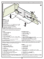
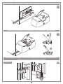
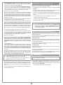
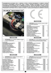
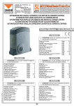
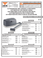
1
1
Description : prodotti Technocity (lamp. fotocellule ecc.)
INSTALLAZIONE TIPO BL1924
5
8
4
11
3
7
LEGENDA
12
1 Motoriduttore (SX)
2 Motoriduttore (DX)
3 Fotocellula interna
4 Fotocellula esterna
5 Lampeggiatore
6 Selettore a chiave
7 Elettroserratura
8 Antenna esterna (Cavo coassiale RG58 Impedenza 50Ω)
9 Interruttore onnipolare con apertura contatti min. 3 mm
10 Cavo alimentazione principale 230 Vac
11 Canalatura per collegamenti motori 24 Vdc
12 Canalatura per collegamenti a bassa tensione
13 Programmatore elettronico
Attenzione: Lo schema rappresentato è puramente indicativo e
viene fornito come base di lavoro al fine di consentire una scelta dei
componenti elettronici Cardin da utilizzare. Detto schema non costituisce pertanto vincolo alcuno per l'esecuzione dell'impianto
2
6
23
13
10
0V
-50
Hz
9
LEGEND
1 Geared motor (SX - left)
2 Geared motor (DX - right)
3 Internal photocells
4 External photocells
5 Warning lights
6 Mechanical selector switch
7 Electric locking device
8 External antenna (RG58 coaxial cable - impedance 50Ω)
9 All-pole circuit breaker with a minimum of 3 mm between the
contacts
10 Mains cable 230 Vac
11 Channelling for the motor connection cable 24 Vdc
12 Channelling route for low voltage wires
13 Electronic programmer
Attention: The drawing is purely indicative and is supplied as working base from which to choose the Cardin electronic components
making up the installation. This drawing therefore does not lay down
any obligations regarding the execution of the installation.
Zeichenerklärung
1 Getriebemotor (SX - links)
2 Getriebemotor (DX - rechts)
3 Interne Lichtschranke
4 Externe Lichtschranke
5 Blinklicht
6 Schlüsselschalter
7 Elektroverriegelung
8 Antenne (Koaxialkabel RG58 Impedanz 50Ω)
9 Allpoliger Schalter mit Kontaktenabstand von mindestens 3 mm
10 Hauptversorgungskabel 230 Vac
11 Kanalverlauf für motorverbindungskabel 24 Vdc
12 Kanalverlauf für Anschluss auf Niederspannung
13 Elektronische Steuereinheit
NOMENCLATURE
1 Motoréducteur (SX - gauche)
2 Motoréducteur (DX - droite)
3 Cellule photoélectrique intérieure
4 Cellule photoélectrique extérieure
5 Clignoteur
6 Sélecteur à clé
7 Serrure électrique
8 Antenne (Câble coaxial RG58 - Impédance 50Ω)
9 Interrupteur omnipolaire avec ouverture des contacts d'au
moins 3 mm.
10 Câble d’alimentation principale 230 Vac
11 Chemin de câble branchement moteurs 24 Vdc
12 Chemin pour branchement basse tension
13 Armoire électronique
Attention: le schéma, diffusé à titre purement indicatif, est destiné
à vous aider dans le choix des composants électroniques Cardin
à utiliser. Par conséquent, il n'a aucune valeur obligatoire quant
à la réalisation de l'installation.
LEYENDA
1 Motorreductor (SX - izquierda)
2 Motorreductor (DX - derecha)
3 Fotocélula interior
4 Fotocélula exterior
5 Relampagueador
6 Selector con llave
7 Electrocerradura
8 Antena exterior (Cable coaxial RG58 Impedancia 50Ω)
9 Interruptor omnipolar con apertura entre los contactos de 3 mm.
como mínimo.
10 Cable de alimentación principal 230 Vac
11 Canaleta para motor cable 24 Vdc
Achtung: Bei dem dargestellten Plan handelt es sich nur um ungefähre
Angaben und er wird als Arbeitsgrundlage geliefert, um eine Auswahl der
zu benutzenden elektronischen Komponenten von Cardin zu erlauben. Der
besagte Plan ist daher für die Ausführung der Anlage nicht bindend.
12 Canaleta para el conexionado a baja tensión
13 Centralita electrónica
Atención: La pantalla que se muestra es sólo indicativa y se suministra
como base de trabajo, con el fin de permitir una elección de los componentes electrónicos Cardin por utilizar; en consecuencia, dicho esquema
no constituye vínculo alguno para la ejecución del sistema.
2
All rights reserved. Unauthorised copying or use of the information contained in this document is punishable by law
Drawing number : DI0446
Product Code : BL1924
ESEMPIO D'INSTALLAZIONE - Installation example - Exemple d'installation - Anlagenart - INSTALACIÓN ESTÁNDAR