1
IS1 I/O-Modules
CPU & Power Module and Sockets for Installation in Zone 1 / Div. 1 Series 9440/22, 9490
Function/Characteristics
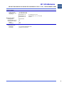
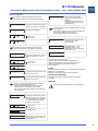
Sub-D connectors X1, X2, X3
The CPU & Power Module contains power supply unit for
intrinsically safe supply of power to the I/O modules and field
circuits. The power supply unit is fitted with undervoltage
monitoring.
The CPU has the function of a gateway between the internal bus
in an IS1 field station and the Ex i fieldbus that connects the field
station to the automation system via a fieldbus isolating repeater.
The I/O modules are supplied with power and communicate via
the BusRail. The interface of the CPU & Power Module with the
internal data bus on the BusRail is designed with redundancy.
The electronics have a flameproof enclosure and are connected
to the socket using Ex d and Ex i plug connectors. The auxiliary
power connection is made in Ex e or using conduit.
Components
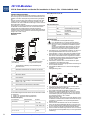
Overview
5 3
8 6
Terminal assignment
Pin No.
3
5
Function
RxD/TxD (+)
GND
6
8
1, 2, 4, 7, 9
PWR (+)
RxD/TxD (-)
--
The national installation instructions
(e.g. IEC/EN 60079-14) must be observed.
Intrinsically-safe and non-intrinsically safe circuits must
not be used in a common cable duct!
Ensure that there is a distance of at least 50 mm
between connection facilities of intrinsically-safe and
non-intrinsically safe circuits!
1
2
3
4
✗
15
✗
6
7
8
9
10
11
12
13
12223E00
socket with Ex e terminal
(without module)
1
2
3
4
5
6
7
8
9
10
11
12
13
14
15
socket with a pig tail
(with plugged-in module)
Protective cover (opened) to ensure ingress protection
IP30
Ex e terminal (only for the socket 9490/11-12)
Detent lever for removing the module from the socket
Socket for the module
clamp screw for DIN rail
Socket for the module
Detent lever for removing the module from the socket
LCD-indication
LED for status or fault indication (further information
see "LED Indications and Troubleshooting")
Buttons <▲>, <▼>
Sub-D connector X1 (process bus, primary)
Sub-D connector X2 (process bus, redundant)
Sub-D connector X3 (ServiceBus)
Pig tail (only for the socket 9490/13-12)
CPU & Power Module
Power supply connection
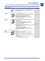
For the power supply connection there are two different sockets
available:
✗ 9490/11-12: Connection by means of Ex e terminals
✗ 9490/13-12: Connection by means of a pig tail
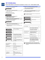
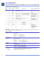
Terminal assignment
Ex e terminal
Terminal No.
1
2
4
6
3, 5, 7, 8, 9, 10, 11, 12,
13, 14, 15, 16
2
www.stahl-ex.com
Pig tail
Conductor No.
1
2
2
3
--
Description
Data B (+)
Reference potential for device
interface
Supply voltage (device)
Data A (-)
not connected
Designing
14
5
12224E00
Function
+ 24 V DC
0V
N (90...253 V AC)
L (90...253 V AC)
no cable
connection
Operating Instructions for the IS1-System
✗
✗
✗
The module is intended for IS 1 field stations and can be
installed in hazardous areas of Zone 1/Division 1,
Zone 2/Division 2, Zone 21 or Zone 22.
For installation in hazardous areas the CPU & Power Module
with the designated socket must be fitted into an enclosure
which complies with recognised ingress protection
requirements according to IEC/EN 60079-0 for the respective
zone (e.g. B. R. STAHL Type 8126)
Ensure that the CPU & Power Module conforms with the
voltage range of the power supply.
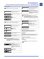
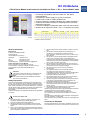
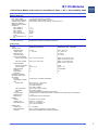
The module is installed for designated use on the IS1 BusRail.
Operation of the module is only admissible in three assembly
positions:
assembly direction upwards:
BusRail
BusRail
05683E00
✗
✗
✗
✗
✗
✗
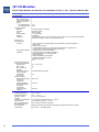
The primary CPU & Power Module must be installed at the
first slot of the BusRail.
The redundant CPU & Power Module must be installed at the
second slot of the BusRail.
When used in hazardous areas suitable fieldbus isolating
repeaters (e.g. B.R. STAHL
Series 9185 or 9186) must be used between the fieldbus
connections (X1, X2, X3) and the automation system.
This also applies if the CPU & Power Module is installed in
the safe area and the fieldbus electric circuits of connected
I/O modules lead to hazardous areas.
The DIN rail of the BusRail must be connected to
equipotential bonding of the hazardous area.
Work at the connected power supply electric circuits (Ex e) is
permitted only if de-energised.
After connecting the power supply ensure ingress protection
IP30 at the Ex e terminal (e.g. using a special cover)!
162277 / 9440607310
2012-03-06·BA00·III·en·04