1
IS1 I/O-Modules
CPU & Power Module and Sockets for Installation in Zone 1 / Div. 1 Series 9440/22, 9490
Assembly and Installation
The national installation instructions (e.g. IEC/EN
60079-14) must be observed.
Intrinsically-safe and non-intrinsically safe circuits must
not be used in a common cable duct!
Ensure that there is a distance of at least 50 mm
between connection facilities of intrinsically-safe and
non-intrinsically safe circuits!
Work on the Ex e terminals or pig tail is only permitted
if de-energised!
If the field station is equipped with two CPU and Power
Modules (primary and redundant), both CPU & Power
Modules must be de-energised or pulled out of the
socket!
It is allowed to connect to the socket either only power
supply 20...35 V DC for the CPM 9440/22-01-11 or
90...230 V AC for the CPM 9440/22-01-21.
Simultaneous connection of both power supplies is not
permitted!
Unused conductors at the socket with a pig tail must be
insulated (e.g. by connecting to an Ex e terminal)!
Replacing the Socket
Work on the Ex e terminals or pig tail is only permitted
if de-energised!
•
•
•
•
•
•
•
•
•
•
•
•
•
•
•
•
Disconnect the power supply.
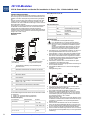
Push the detent levers (3 and 7) into position "II".
Vertically pull out the module from the socket until the stop.
Push the detent levers into position "I".
Vertically remove the module from the socket.
Remove the power supply from the Ex e terminal or disconnect the pig tail from the power supply.
Pull the fieldbus connections out of the Sub-D connectors.
Loosen the clamping screws of the socket.
Remove the socket vertically from the BusRail.
Position the socket vertically onto the BusRail.
Engage the socket by slightly pressing it.
Tighten the clamp screws of the socket in order to fix the
socket on the BusRail.
Plug the module vertically into the socket.
Engage the module by slightly pressing it.
Connect the fieldbus again to the Sub-D connectors.
Reconnect the power supply.
Parameterisation and Commissioning
Parameterisation and commissioning of CPM and
connected I/O modules is carried out using the
automation system and Service Bus (optional).
Only the fieldbus address of the CPM must be set
directly at the socket.
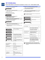
Using the buttons of the LCD-display in the socket it is
possible:
to set the fieldbus address of the CPU & Power Module
and
to display information about the CPU & Power Module
and the I/O modules installed on the BusRail.
The CPU & Power Module can be safely connected or
disconnected during operation in a hazardous area (hot
swap).
Up to eight I/O modules can be operated at the
CPU & Module.
The Sub-D-connectors can be safely connected or
disconnected during operation in a hazardous area
(hot swap).
Assembly on the BusRail
Operation of the module is permissible only in the
following assembly positions:
Socket assembly: Vertical assembly with
LCD-indication below, on the left or right.
Position the socket vertically onto the first slot of the BusRail.
Engage the socket by slightly pressing it.
Tighten the clamp screws (5) of the socket in order to fix the
socket on the BusRail.
• If necessary, install the socket for the redundant module at
the second slot of the BusRail.
• Push the detent levers (3 and 7) into position "I".
• Position the module vertically onto the socket.
• Engage the module by slightly pressing it.
• If necessary, install the redundant module at the second
socket.
• Connect the socket to the power supply (for terminal
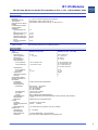
assignment of the Ex e terminal or pig tail see "Components").
• After connecting the power supply ensure that the
Ex e terminal adheres to ingress protection IP30 and the
unused conductors of the pig tail are insulated!
• Connect the fieldbus to the Sub-D connector X1 of the
socket.
• If necessary, connect the redundant fieldbus to the Sub-D
socket X2 and/or Service Bus to the Sub-D connector X3 of
the socket.
Replacing the Module
• Push the detent levers (3 and 7) into position "II".
• Vertically pull out the module from the socket until the stop.
• Push the detent levers into position "I".
• Vertically remove the module from the socket.
• Position a new module vertically onto the socket.
• Engage the module by slightly pressing it.
Start-Up
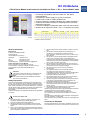
After connecting the power supply the CPU § Power Module
boots. After successful booting the LCD-display switches over to
the system level.
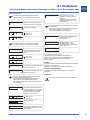
FBAdr
5
Operating Instructions for the IS1-System
I/O
OK
12258E00
Setting the Fieldbus Address
After setting the fieldbus address the CPU & Power
Module reboots again.
The fieldbus address is permanently saved and is also
available after reset or recommissioning.
•
•
•
www.stahl-ex.com
FB
OK
The fieldbus address can be set only if the
CPU & Power Module is not in Data Exchange mode.
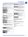
• Press „▲“ and „▼“ simultaneously.
✔ The following indication is displayed:
CPM
active
9440/15-01-11
• Press „▲“ and „▼“ simultaneously.
✔ The following indication is displayed:
12259E00
CPM
active
FB addr :
5
• Press „▲“ and „▼“ simultaneously.
✔ The following indication is displayed:
12260E00
set FB address
select:
5
•
12261E00
Press the button „▲“ or „▼“ until the desired fieldbus address
is set.
When pressing the button continuously the value is
being changed rapidly.
The setting range reaches from 0 to 127.
162277 / 9440607310
2012-03-06·BA00·III·en·04
3