1
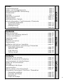
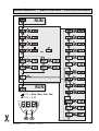
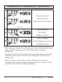
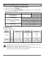
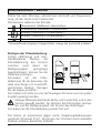
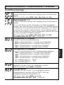
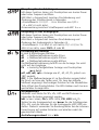
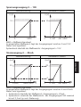
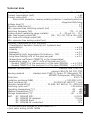
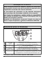
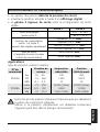
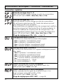
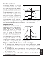
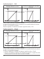
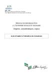
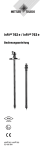
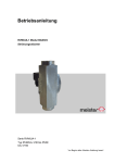
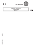
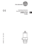
Bedienungsanleitung Operating instructions Notice utilisateurs R ENGLISH FRANÇAIS Sachnr. 704012/00 10/05 Elektronischer Drucksensor Electronic pressure sensor Capteur de pression électronique PF00xA DEUTSCH R Sicherheitshinweise . . . . . . . . . . . . . . . . . . . . . . . . . . . . . . . . Seite 5 Bedien- und Anzeigeelemente . . . . . . . . . . . . . . . . . . . . . . . . Seite 5 Bestimmungsgemäße Verwendung . . . . . . . . . . . . . . . . . . . . . Seite 6 Betriebsarten . . . . . . . . . . . . . . . . . . . . . . . . . . . . . . . . . . . . . Seite 7 Montage . . . . . . . . . . . . . . . . . . . . . . . . . . . . . . . . . . . . . . . . Seite 8 Elektrischer Anschluß . . . . . . . . . . . . . . . . . . . . . . . . . . . . . . Seite 10 Programmieren . . . . . . . . . . . . . . . . . . . . . . . . . . . . . . . . . . Seite 11 Inbetriebnahme / Betrieb . . . . . . . . . . . . . . . . . . . . . . . . . . . Seite 12 Technik-Information / Funktionsweise / Parameter Einstellbare Parameter . . . . . . . . . . . . . . . . . . . . . . . . . . Seite 13 Technische Daten . . . . . . . . . . . . . . . . . . . . . . . . . . . . . . Seite 18 Maßzeichnung . . . . . . . . . . . . . . . . . . . . . . . . . . . . . . . Seite 48 Einstellbereiche . . . . . . . . . . . . . . . . . . . . . . . . . . . . . . . Seite 49 DEUTSCH Inhalt Safety instructions . . . . . . . . . . . . . . . . . . . . . . Controls and indicating elements . . . . . . . . . . . Function and features . . . . . . . . . . . . . . . . . . . Operating modes . . . . . . . . . . . . . . . . . . . . . . Installation . . . . . . . . . . . . . . . . . . . . . . . . . . . Electrical connection . . . . . . . . . . . . . . . . . . . . Programming . . . . . . . . . . . . . . . . . . . . . . . . . Installation and set-up / operation . . . . . . . . . . Technical information / Functioning / Parameters Adjustable parameters . . . . . . . . . . . . . . . . Technical data . . . . . . . . . . . . . . . . . . . . . . Scale drawing . . . . . . . . . . . . . . . . . . . . . . Setting ranges . . . . . . . . . . . . . . . . . . . . . . . . . . . . . . . . . . . . . . . page 20 . . . . . . . . . page 20 . . . . . . . . . page 21 . . . . . . . . . page 22 . . . . . . . . . page 23 . . . . . . . . . page 25 . . . . . . . . . page 26 . . . . . . . . . page 27 . . . . . . . . . . . . . . . . Remarque sur la sécurité . . . . . . . . . . . . . . . . . . Eléments de service et d’indication . . . . . . . . . . . Fonctionnement et caractéristiques . . . . . . . . . . . Modes de fonctionnement . . . . . . . . . . . . . . . . . Montage . . . . . . . . . . . . . . . . . . . . . . . . . . . . . Raccordement électrique . . . . . . . . . . . . . . . . . . Programmation . . . . . . . . . . . . . . . . . . . . . . . . . Mise en service / Fonctionnement . . . . . . . . . . . . Informations techniques / Fonctions / Paramètres Paramètres réglables . . . . . . . . . . . . . . . . . . Données techniques . . . . . . . . . . . . . . . . . . Dimensions . . . . . . . . . . . . . . . . . . . . . . . . . Plages de réglage . . . . . . . . . . . . . . . . . . . . . . . . . . . . . . . . . . . . . . . . . . . page 34 . . . . . . . page 34 . . . . . . . page 35 . . . . . . . page 36 . . . . . . . page 37 . . . . . . . page 39 . . . . . . . page 40 . . . . . . . page 41 . . . . . . . . . . . . . . . . . . . . . . . . . . . . . . . . . . . . page page page page ENGLISH Contents 28 33 48 49 2 . . . . . . . . . . . . . . . . . . . . . . . . page page page page 42 47 48 49 FRANÇAIS Contenu Menü-Übersicht / Menu structure / Structure du menu RUN M S S M M M M S S M M M M S S M M M M S S M M M M S S M S M M M M S M S M S M M M M M S M M S S M M M S RUN M M S M OU2 = Hno, Hnc, Fno, Fnc OU2 = I, U M S M M S Mode/Enter M Set M S M M PF00xA S Sachnr. 704012 M 3 Programmieren / Programming / Programmation Mode/Enter Set 1 Parameter aufrufen 1x Select parameters Sélectionner les paramètres Mode/Enter Set 2x ... Werte einstellen* 2 Set Values* Mode/Enter Set > 5s Régler la valeurs* Werte bestätigen 3 Mode/Enter Set 1x Acknowledgement of values Confirmer la valeur *Wert verringern: Lassen Sie die Anzeige bis zum maximalen Einstellwert laufen. Danach beginnt der Durchlauf wieder beim minimalen Einstellwert. *Decrease the value: Let the display of the parameter value move to the maximum setting value. Then the cycle starts again at the minimum setting value. *Réduire la valeur du paramètre: Laisser l'affichage de la valeur du paramètre aller jusqu'à la valeur de réglage maximum. Ensuite le cycle recommence à la valeur de réglage minimum. 4 Sachnr. 704012 PF00xA Sicherheitshinweise Lesen Sie vor der Inbetriebnahme des Gerätes die Produktbeschreibung. Vergewissern Sie sich, daß sich das Produkt uneingeschränkt für die betreffende Applikationen eignet. Die Mißachtung von Anwendungshinweisen oder technischen Angaben kann zu Sach- und/oder Personenschäden führen. Prüfen Sie in allen Applikationen die Verträglichkeit der Produktwerkstoffe (s. Technische Daten) mit den zu messenden Druckmedien. Beachten Sie die Hinweise für den sicheren Einsatz in explo→ ATEX-3D-Betriebsanleitung). sionsgefährdeten Bereichen (→ Bedien- und Anzeigeelemente 1 2 Set 3 DEUTSCH Mode/Enter 4 Anzeige des Systemdrucks1), 1 Anzeige der Parameter und Parameterwerte. Anzeige des Schaltzustands; leuchtet, 2 x LED rot 2 wenn Ausgang I / II durchgeschaltet ist. Anwahl der Parameter und Menüpunkte Programmiertaste 3 Mode / Enter Bestätigen der Parameterwerte. Einstellen der Parameterwerte Programmiertaste (kontinuierlich durch Dauerdruck; schrittweise 4 Set durch Einzeldruck). 1) 3-stellige Anzeige im Minusbereich: -.XX = -0,XX 7-Segment-Anzeige 5 Bestimmungsgemäße Verwendung • Der Drucksensor erfaßt den Systemdruck, • zeigt ihn durch ein Display an • und erzeugt 2 Ausgangssignale entsprechend der eingestellten Ausgangskonfiguration. Ausgang 1 Analogausgang (nur Ausgang 2) Schaltfunktion (Ausgang 1 und Ausgang 2; Funktion getrennt je Ausgang einstellbar) Schaltlogik (gilt für beide Schaltausgänge) Ausgang 2 I: 4 ... 20 mA U: 0 ... 10 V Hysteresefunktion / Schließer (Hno) Hysteresefunktion / Öffner (Hnc) Fensterfunktion / Schließer (Fno) Fensterfunktion / Öffner (Fnc) p-schaltend (PnP) n-schaltend (nPn) Einsatzbereich Druckart: Relativdruck Bestellnummer PF003A PF008A Meßbereich bar PSI MPa mbar inH2O kPa -1,0 ... 25 -15 ... 363 -0,1 ... 2,5 -13 ... 250 -5,0 ... 100 -1,3 ... 25,0 Zulässiger Überlastdruck 100 1 450 10 10 000 (10 bar) 4 000 1 000 (1 MPa) Berstdruck 350 5 070 35 30 000 (30 bar) 12 000 3 000 (3 MPa) Vermeiden Sie statische und dynamische Überdrücke, die den angegebenen Überlastdruck überschreiten. Schon bei kurzzeitiger Überschreitung des Berstdrucks kann das Gerät zerstört werden (Verletzungsgefahr)! 6 Betriebsarten Run-Modus Normaler Arbeitsbetrieb Nach dem Einschalten der Versorgungsspannung befindet sich das Gerät im Run-Modus. Es führt seine Überwachungsfunktion aus und gibt Ausgangssignale entsprechend den eingestellten Parametern. Das Display zeigt den aktuellen Systemdruck an (kann ausgeschaltet werden; → Seite 15). Die roten LEDs signalisieren den Schaltzustand der Ausgänge. Programmier-Modus Einstellen der Parameterwerte Das Gerät geht in den Programmiermodus, wenn ein Parameter angewählt ist und danach die Taste “Set” länger als 5 s gedrückt wird (der Parameterwert wird blinkend angezeigt, danach fortlaufend erhöht). Das Gerät verbleibt auch hier intern im Arbeitsbetrieb. Es führt seine Überwachungsfunktionen mit den bestehenden Parametern weiter aus, bis die Veränderung abgeschlossen ist. Sie können den Parameterwert mit Hilfe der Taste “Set” ändern und mit der Taste “Mode/Enter” bestätigen. Das Gerät geht in den RunModus zurück, wenn danach 15 s lang keine Taste mehr gedrückt wird. 7 DEUTSCH Display-Modus Anzeige der Parameter und Parameterwerte Das Gerät geht durch kurzen Druck auf die Taste “Mode/Enter” in den Display-Modus. Intern verbleibt es im Arbeitsbetrieb. Unabhängig davon können die eingestellten Parameterwerte abgelesen werden: • Kurzer Druck auf die Taste “Mode/Enter” blättert durch die Parameter. • Kurzer Druck auf die Taste “Set” zeigt 15 s lang den zugehörigen Parameterwert. Nach weiteren 15 s geht das Gerät zurück in den Run-Modus. Montage Stellen Sie vor Ein- und Ausbau des Sensors sicher, daß die Anlage druckfrei ist. 1. Schrauben Sie den Sensor in einen G1-Prozeßanschluß. 2. Ziehen Sie den Sensor mit einem Schraubenschlüssel fest. Anzugsdrehmoment: 20Nm. A Das Gehäuse (A) ist drehbar. 41 Durch G1-Prozeßadapter ist der Sensor adaptierbar an unterschiedliche Prozeßanschlüsse. G1-Prozeßadapter sind gesondert als Zubehör zu bestellen. Einschweißadapter Schweißen Sie zuerst den Adapter ein. Montieren Sie dann den Sensor. 8 ifm-Prozeßadapter Montieren Sie zuerst den Adapter (C) an den Sensor, dann Sensor + Adapter mit Hilfe einer Überwurfmutter, eines Klemmflanschs o. ä. (B) an den Prozeßanschluß. ACHTUNG: Eine Garantie für langzeitstabile Dichtwirkung der metallischen Abdichtung besteht nur für einmalige Montage. B C I DEUTSCH Montage des Adapters Schritt 1 Schrauben Sie den Sensor in den Adapter ein. Schritt 2 Spannen Sie Sensor + Adapter in eine Klemmvorrichtung (D). Die Dichtflächen (E) dürfen dabei nicht beschädigt werden. Ziehen Sie den Sensor mit einem Schraubenschlüssel an. Anzugsdrehmoment: 20Nm. 41 D E 9 Elektrischer Anschluß Das Gerät darf nur von einer Elektrofachkraft installiert werden. Befolgen Sie die nationalen und internationalen Vorschriften zur Errichtung elektrotechnischer Anlagen. Spannungsversorgung nach EN50178, SELV, PELV. Schalten Sie die Anlage spannungsfrei und schließen Sie das Gerät folgendermaßen an: 2 x p-schaltend 1 BN 2: OUT2 4: OUT1 2 x n-schaltend 2 WH 2 WH 4 BK 4 BK 3 BU L 2: OUT2 4: OUT1 3 BU L+ L 1 x p-schaltend / 1 x analog 1 x n-schaltend / 1 x analog 1 BN 1 BN 2: OUT2 4: OUT1 L+ 2 WH 2 WH 4 BK 4 BK 3 BU L Steckeransicht (am Gerät) 1 4 2 3 10 1 BN L+ 2: OUT2 4: OUT1 3 BU L+ L Adernfarben bei ifm-Kabeldosen: 1 = BN (braun), 2 = WH (weiß), 3 = BU (blau), 4 = BK (schwarz) Programmieren Mode/Enter Set Mode/Enter Set Drücken Sie die Taste Set und halten Sie sie gedrückt. Der aktuelle Parameterwert wird 5 s lang blinkend angezeigt, 2 3 4 Mode/Enter Set Weitere Parameter verändern: Beginnen Sie wieder mit Schritt 1. danach wird er erhöht* (schrittweise durch Einzeldruck oder kontinuierlich durch Festhalten der Taste). Drücken Sie kurz die Taste Mode/Enter (= Bestätigung). Der Parameter wird erneut angezeigt; der neue Parameterwert ist wirksam. Programmierung beenden: Warten Sie 15 s oder drücken Sie die Mode/Enter-Taste, bis wieder der aktuelle Meßwert erscheint. *Wert verringern: Lassen Sie die Anzeige bis zum maximalen Einstellwert laufen. Danach beginnt der Durchlauf wieder beim minimalen Einstellwert. Stellen Sie die Anzeigeeinheit (Uni) ein, bevor Sie die Schaltgrenzen (SPx, rPx) und die Grenzen für die Analogwerte (ASP, AEP) festlegen. Dadurch vermeiden Sie Rundungsfehler bei der internen Umrechnung auf andere Einheiten und erhalten exakt die gewünschten Werte. Auslieferungszustand: Uni = bar. Wird während des Einstellvorgangs 15 s lang keine Taste gedrückt, geht das Gerät mit unveränderten Werten in den Run-Modus zurück. Das Gerät läßt sich elektronisch verriegeln, so daß unbeabsichtigte Fehleingaben verhindert werden: Drücken Sie im Run-Modus 10 s lang die beiden Programmiertasten. Sobald die Anzeige verlischt, ist das Gerät verriegelt oder entriegelt. Auslieferungszustand: Nicht verriegelt. Bei verriegeltem Gerät erscheint kurzzeitig in der Anzeige, wenn versucht wird, Parameterwerte zu ändern. 11 DEUTSCH 1 Drücken Sie die Taste Mode/Enter, bis der gewünschte Parameter im Display erscheint. Inbetriebnahme / Betrieb Prüfen Sie nach Montage, elektrischem Anschluß und Programmierung, ob das Gerät sicher funktioniert. Störanzeigen während des Betriebs: Überlastdruck (Meßbereich überschritten). Unterlastdruck (Meßbereich unterschritten). Blinkend: Kurzschluß in Schaltausgang 1*. Blinkend: Kurzschluß in Schaltausgang 2*. Blinkend: Kurzschluß in beiden Schaltausgängen*. *Der betreffende Ausgang ist abgeschaltet, solange der Kurzschluß andauert. Reinigen der Filterabdeckung Sollten zähflüssige und rückstandbildende Medien die Filterabdeckung des Sensors zusetzen (und damit die Meßgenauigkeit geringfügig beeinträchtigen), können Sie die Abdeckung reinigen. Schrauben Sie die Filterabdeckung (B) ab (benutzen Sie A B dazu eine Zange mit kunststoffgeschützten Backen). Reinigen Sie die Kappe gründlich. Der Stutzen (A) sollte nur von fachkundigem Personal und mit großer Sorgfalt gereinigt werden. Etwaige Mediumsrückstände dürfen nicht verdichtet und in den Stutzen gepreßt werden. Sie könnten das Filtersystem verstopfen und die Meßgenauigkeit des Sensors beeinträchtigen. Schrauben Sie die Filterabdeckung wieder fest auf. Der Sensor ist ausreichend gegen rauhe Umgebungsbedingungen geschützt (Schutzart IP 67). Sie können die Schutzart durch spezielles Zubehör erhöhen (Bestell-Nr. E30043). 12 Technik-Information / Funktionsweise / Parameter Einstellbare Parameter Rückschaltpunkt 1 / 2 Unterer Grenzwert, bei dem der Ausgang seinen Schaltzustand ändert. rPx ist stets kleiner als SPx. Es können nur Werte eingegeben werden, die unter dem Wert für SPx liegen. Bei Veränderung des Schaltpunkts wird der Rückschaltpunkt mitgezogen (der Abstand zwischen SPx und rPx1 bleibt konstant). Ist der Abstand größer als der neue Schaltpunkt, wird er automatisch reduziert (rPx wird auf den minimalen Einstellwert gesetzt). rP2 ist nur aktiv, wenn OU2 = Hnc, Hnc, Fno oder Fnc. Einstellbereiche für SPx / rPx: → Seite 49. Konfiguration für Ausgang 1 Es sind 4 Schaltfunktionen einstellbar: - Hno = Hysteresefunktion / normally open (Schließer) - Hnc = Hysteresefunktion / normally closed (Öffner) - Fno = Fensterfunktion / normally open (Schließer) - Fnc = Fensterfunktion / normally closed (Öffner) Konfiguration für Ausgang 2 Es sind 4 Schaltfunktionen und 2 Analogsignale einstellbar: - Hno = Hysteresefunktion / normally open (Schließer) - Hnc = Hysteresefunktion / normally closed (Öffner) - Fno = Fensterfunktion / normally open (Schließer) - Fnc = Fensterfunktion / normally closed (Öffner) - I = Analogausgang 4 ... 20 mA - U = Analogausgang 0 ... 10 V Analogstartpunkt Meßwert, bei dem 4 mA / 0 V ausgegeben werden. ASP ist nur aktiv, wenn OU2 = I oder U. Analogendpunkt Meßwert, bei dem 20 mA / 10 V ausgegeben werden. Mindestabstand zwischen ASP und AEP = 25% des Meßbereichsendwerts (Skalierfaktor 4). AEP ist nur aktiv, wenn OU2 = I oder U. Einstellbereiche für ASP / AEP: → Seite 49. 13 DEUTSCH Schaltpunkt 1 / 2 Oberer Grenzwert, bei dem der Ausgang seinen Schaltzustand ändert. SP2 ist nur aktiv, wenn OU2 = Hnc, Hnc, Fno oder Fnc. Erweiterte Funktionen Dieser Menüpunkt enthält ein Untermenü mit Parametern, die selten benutzt werden. Durch kurzen Druck auf die Set-Taste erhalten Sie Zugang zu diesen Parametern. Min-Max-Speicher für Systemdruck • HI: Anzeige des höchsten gemessenen Drucks • LO: Anzeige des niedrigsten gemessenen Drucks Löschen des Speichers: - Drücken Sie die “Mode/Enter”-Taste, bis “HI” oder “LO” erscheint. - Drücken Sie die “Set”-Taste und halten Sie sie fest, bis die Anzeige “- - -” erscheint. - Drücken Sie dann kurz die “Mode/Enter”-Taste. Nullpunkt-Kalibrierung (Calibration offset) Der interne Meßwert (Arbeitswert des Sensors) wird gegenüber dem realen Meßwert verschoben. • Einstellbereich: -5 ... +5% des Meßbereichsendwerts (bei Skalierung im Auslieferungszustand: ASP = 0% und AEP = 100%), • in Schritten von 0,1% des Meßbereichsendwerts. Zurücksetzen der Kalibrierdaten (Calibration reset) Setzt die mit COF eingestellte Kalibrierung zurück auf Werkseinstellung. - Drücken Sie die “Mode/Enter”-Taste, bis CAr angezeigt wird. - Drücken Sie die “Set”-Taste und halten Sie sie fest, bis die Anzeige “- - -” erscheint. - Drücken Sie dann kurz die “Mode/Enter”-Taste. Verzögerungszeit für die Schaltausgänge dSx = Einschaltverzögerung; drx = Ausschaltverzögerung Der Ausgang ändert seinen Schaltzustand nicht sofort bei Eintritt des Schaltereignisses, sondern erst nach Ablauf der Verzögerungszeit. Besteht das Schaltereignis nach Ablauf der Verzögerungszeit nicht mehr, ändert sich der Schaltzustand des Ausgangs nicht. • Einstellbereich: 0 / 0,1 ... 50 s in Schritten von 0,1 s (0 = Verzögerungszeit ist nicht aktiv). • Anzeige in Sekunden. dS2 und dr2 sind nicht wirksam, wenn OU2 = I oder U. Schaltlogik (Ausgänge) Es sind 2 Einstellungen wählbar: - PnP = positiv schaltend - nPn = negativ schaltend Die Einstellung gilt für beide Schaltausgänge. 14 Dämpfung für das Analogsignal Mit dieser Funktion lassen sich Druckspitzen von kurzer Dauer oder hoher Frequenz ausfiltern. dAA-Wert = Ansprechzeit zwischen Druckänderung und Änderung des Analogsignals in Sekunden (s). • Einstellbereich: 0 (= dAA ist nicht aktiv) / 0,1 s / 0,5 s / 2 s. dAA ist nur aktiv, wenn OU2 = I oder U. Einstellung der Anzeige Es sind 9 Einstellungen wählbar: d1 = Meßwertaktualisierung alle 50 ms d2 = Meßwertaktualisierung alle 200 ms d3 = Meßwertaktualisierung alle 600 ms Die Meßwertaktualisierung betrifft nur die Anzeige. Sie wirkt nicht auf die Ausgänge. Ph = kurzeitig festgehaltene Anzeige von Druckspitzen (peak hold). rd1, rd2, rd3, rph = Anzeige wie d1, d2, d3, Ph; jedoch um 180° gedreht. OFF = Die Meßwertanzeige ist im Run-Modus ausgeschaltet. Bei Druck auf eine der Tasten wird 15 s lang der aktuelle Meßwert angezeigt. Nochmaliges Drücken auf die Mode/EnterTaste öffnet den Display-Modus. Die LEDs bleiben auch bei ausgeschalteter Anzeige aktiv. Anzeigeeinheit Meßwert und Werte für SPx, rPx, ASP und AEP können in folgenden Einheiten angezeigt werden: bAr (= bar / mbar), PA (= MPA / kPa), PSI, H2O (inH2O). Stellen Sie die Anzeigeeinheit ein, bevor Sie die Schaltgrenzen (SPx, rPx) und die Grenzen für die Analogwerte (ASP, AEP) einstellen. Dadurch vermeiden Sie Rundungsfehler bei der internen Umrechnung auf andere Einheiten und erhalten exakt die gewünschten Werte. Auslieferungszustand: Uni = bAr. 15 DEUTSCH Dämpfung für das Schaltsignal Mit dieser Funktion lassen sich Druckspitzen von kurzer Dauer oder hoher Frequenz ausfiltern. dAP-Wert = Ansprechzeit zwischen Druckänderung und Änderung des Schaltzustands in Sekunden. • Einstellbereich: 0 / 0,01 ... 4 s in Schritten von 0,01 s (0 = dAP ist nicht aktiv). Zusammenhang zwischen Schaltfrequenz und dAP: fmax = Hysteresefunktion: Die Hysterese hält den P Schaltzustand des Ausgangs stabil, wenn der Systemdruck um SP den Sollwert schwankt. rP Bei steigendem Systemdruck schaltet der Ausgang bei Erreichen des Schaltpunkts (SPx); 1 fällt der Systemdruck wieder ab, 0 schaltet der Ausgang erst dann 1 zurück, wenn der Rückschalt0 punkt (rPx) erreicht ist. Die Hysterese ist einstellbar: Zuerst wird der Schaltpunkt dann im gewünschten Abstand der Rückschaltpunkt. Fensterfunktion: Die Fensterfunktion erlaubt die Gutbereich P Überwachung eines definierten Gutbereichs. SP Bewegt sich der Systemdruck zwischen Schaltpunkt (SPx) und rP Rückschaltpunkt (rPx), ist der Ausgang durchgeschaltet 1 (Fensterfunktion / Schließer) bzw. 0 geöffnet (Fensterfunktion/ Öffner). 1 Die Breite des Fensters ist ein0 stellbar durch den Abstand von SPx zu rPx. SPx = oberer Wert, rPx = unterer Wert. Hysterese t Hno Hnc festgelegt, t Fno Fnc Skalieren des Meßbereichs (Analogausgang) • Mit dem Parameter Analogstartpunkt (ASP) legen Sie fest, bei welchem Meßwert das Ausgangssignal 4 mA / 0 V beträgt. • Mit dem Parameter Analogendpunkt (AEP) legen Sie fest, bei welchem Meßwert das Ausgangssignal 20 mA / 10 V beträgt. • Mindestabstand zwischen ASP und AEP = 25% des Meßbereichsendwerts (Skalierfaktor 4). 16 Spannungsausgang 0 ... 10V Werkseinstellung Meßbereich skaliert U [V] U [V] 10 10 -1 0 MEW P -1 0 ASP AEP MEW P MEW = Meßbereichsendwert Im eingestellten Meßbereich liegt das Ausgangssignal zwischen 0 und 10 V. Weiter wird signalisiert: Systemdruck oberhalb des Meßbereichs: Ausgangssignal > 10 V. Stromausgang 4 ... 20 mA Werkseinstellung Meßbereich skaliert I [mA] 20 20 4 4 -1 0 (ASP) MEW (AEP) P -1 DEUTSCH I [mA] 0 ASP AEP MEW P MEW = Meßbereichsendwert Im eingestellten Meßbereich liegt das Ausgangssignal zwischen 4 und 20 mA. Weiter wird signalisiert: • Systemdruck oberhalb des Meßbereich: Ausgangssignal > 20 mA. • Systemdruck unterhalb des Meßbereichs: das Ausgangssignal fällt maximal bis auf 3,2 mA (je nach Skalierung). 17 Technische Daten Betriebsspannung [V] . . . . . . . . . . . . . . . . . . . . . . . . . . . . . . . 20 ... 30 DC Stromaufnahme [mA] . . . . . . . . . . . . . . . . . . . . . . . . . . . . . . . . . . . . . < 60 Strombelastbarkeit je Schaltausgang [mA]. . . . . . . . . . . . . . . . . . . . . . . 250 Kurzschlußschutz; verpolungssicher / überlastfest,Watchdog integriert Spannungsabfall [V] . . . . . . . . . . . . . . . . . . . . . . . . . . . . . . . . . . . . . . . < 2 Bereitschaftsverzögerungszeit [s] . . . . . . . . . . . . . . . . . . . . . . . . . . . . . 0,2 Min. Ansprechzeit Schaltausgänge [ms] . . . . . . . . . . . . . . . . . . . . . . . . . . 3 Schaltfrequenz [Hz] . . . . . . . . . . . . . . . . . . . . . . . . . . . . . . . . 170 ... 0,125 Analogausgang (Meßbereich skalierbar) . . . . . . . . . . 4 ... 20 mA / 0 ... 10 V Max. Bürde Stromausgang [Ω] . . . . . . . . . (UB - 10) x 50; 700 bei UB = 24V Min Bürde bei Spannungsausgang [Ω] . . . . . . . . . . . . . . . . . . . . . . . . 2000 Min. Anstiegszeit Analogausgang [ms] . . . . . . . . . . . . . . . . . . . . . . . . . . . 3 Genauigkeit / Abweichungen (in % der Spanne)1) - Kennlinienabweichung (Linearität, einschließlich Hysterese und Wiederholgenauigkeit)2) . . . . . . . . . . . . . . . . . . . . . . . . . . . . . . . < ± 0,6 - Linearität. . . . . . . . . . . . . . . . . . . . . . . . . . . . . . . . . . . . . . . . . . . < ± 0,5 - Hysterese . . . . . . . . . . . . . . . . . . . . . . . . . . . . . . . . . . . . . . . . . . < ± 0,1 - Wiederholgenauigkeit (bei Temperaturschwankungen < 10K) . . . . . < ± 0,1 - Langzeitstabilität (in % der Spanne pro Jahr) . . . . . . . . . . . . . . . . . < ± 0,1 - Temperaturkoeffizienten (TK) im kompensierten Temperaturbereich 0 ... 60°C (in % der Spanne pro 10 K) - Größter TK des Nullpunkts / der Spanne (PF003A). . . . . . . . < ± 0,1 / 0,2 - Größter TK des Nullpunkts / der Spanne (PF008A). . . . . . . . < ± 0,1 / 0,4 Werkstoffe in Kontakt mit Medium . . . . . . . . . . . . . . . . . . . . V4A (1.4404); Keramik (99,9 % Al2O3); PTFE Gehäusewerkstoffe . . . . . . . . . . V4A (1.4404); PBTP (Pocan); PC (Macrolon); PEI; EPDM/X (Santoprene); FPM (Viton) Schutzart . . . . . . . . . . . . . . . . . . . . . . . . . . . . . . . . . . . . . . . . . . . . . IP 67 Schutzklasse . . . . . . . . . . . . . . . . . . . . . . . . . . . . . . . . . . . . . . . . . . . . . . III Isolationswiderstand [MΩ] . . . . . . . . . . . . . . . . . . . . . . . . > 100 (500 V DC) Schockfestigkeit [g] . . . . . . . . . . . . . . . . . . . . 50 (DIN / IEC 68-2-27, 11ms) Vibrationsfestigkeit [g] . . . . . . . . . . . . . 20 (DIN / IEC 68-2-6, 10 - 2000 Hz) Schaltzyklen min. . . . . . . . . . . . . . . . . . . . . . . . . . . . . . . . . . 100 Millionen Umgebungstemperatur [°C] . . . . . . . . . . . . . . . . . . . . . . . . . . . . -20 ... +60 Mediumtemperatur [°C]. . . . . . . . . . . . . . . . . . . . . . . . . . . . . . . -20 ... +60 Lagertemperatur [°C]. . . . . . . . . . . . . . . . . . . . . . . . . . . . . . . . -40 ... +100 EMV IEC 1000/4/2 ESD: . . . . . . . . . . . . . . . . . . . . . . . . . . . . . 4 / 8 KV IEC 1000/4/3 HF gestrahlt: . . . . . . . . . . . . . . . . . . . . . . . . . 10 V/m IEC 1000/4/4 Burst: . . . . . . . . . . . . . . . . . . . . . . . . . . . . . . . . 2 KV IEC 1000/4/6 HF leitungsgebunden: . . . . . . . . . . . . . . . . . . . . 10 V 1) 2) alle Angaben bezogen auf Turn down von 1:1 Grenzpunkteinstellung nach DIN 16086 18 Safety instructions Read the product description before installing the unit. Ensure that the product is suitable for your application without any restrictions. Non-adherence to the operating instructions or technical data can lead to personal injury and/or damage to property. In all applications check compliance of the product materials (see Technical data) with the media to be measured. Observe the instructions for the safe use in hazardous areas → Operating instructions ATEX-3D). (→ Controls and indicating elements 1 2 Mode/Enter Set 3 4 7-segment display 1 2 2 x LED red 3 Mode / Enter button 4 Set button 1) Display of the system pressure1), display of parameters and parameter values. Switching status; lights if output I / II has switched. Selection of the parameters and acknowledgement of the parameter values. Setting of the parameter values (scrolling by holding pressed; incremental by pressing briefly). 3-digit display in the minus range: -.XX = -0,XX 20 Function and features • The pressure sensor detects the system pressure, • shows the current system pressure on its display, • and generates 2 output signals according to the set output configuration. Output 1 Analogue output (only output 2) Switching function (output 1 and output 2; function can be selected for each output separately) Output polarity (applies to both switching outputs) Output 2 I: 4 ... 20 mA U: 0 ... 10 V hysteresis function / N.O. (Hno) hysteresis function / N.C. (Hnc) window function / N.O. (Fno) window function / N.C. (Fnc) p-switching (PnP) n-switching (nPn) Applications Type of pressure: relative pressure PF003A PF008A bar PSI MPa mbar inH2O kPa Measuring range -1.0 ... 25 -15 ... 363 -0.1 ... 2.5 -13 ... 250 -5.0 ... 100 -1.3 ... 25.0 Permissible overl. pressure 100 1 450 10 10 000 (10 bar) 4 000 1 000 (1 MPa) Bursting pressure 350 5 070 35 30 000 (30 bar) 12 000 3 000 (3 MPa) Avoid static and dynamic overpressure exceeding the given overload pressure. Even if the bursting pressure is exceeded only for a short time the unit can be destroyed (danger of injuries)! 21 ENGLISH Order no. Operating modes Run mode Normal operating mode At power on the unit is in the Run mode. It carries out its measurement and evaluation functions and provides output signals according to the set parameters. The display shows the current system pressure (can be deactivated; → page 30). The red LEDs indicate the switching state of the outputs. Display mode Indication of parameters and the set parameter values When the "Mode/Enter" button is pressed briefly, the unit passes to the Display mode which allows parameter values to be read. The internal sensing, processing and output functions of the unit continue as if in Run mode. • The parameter names are scrolled with each pressing of the "Mode/Enter" button. • When the "Set" button is pressed briefly, the corresponding parameter value is displayed for 15 s. After another 15 s the unit returns to the Run mode. Programming mode Setting of the parameter values While viewing a parameter value pressing the "Set" button for more than 5 s causes the unit to enter the programming mode. You can alter the parameter value by pressing the "Set" button and confirm the new value by pressing the "Mode/Enter" button. The internal sensing, processing and output functions of the unit continue as if in Run mode with the original parameter values unless a new value is confirmed. The unit returns to the Run mode when no button has been pressed for 15 s. 22 Installation Before mounting and removing the sensor, make sure that no pressure is applied to the system. The housing (A) is freely rotatable. 1. Screw the sensor into a G1 process fitting. 2. Tighten the sensor with a spanner. Tightening torque: 20 Nm. A 41 The unit is adaptable for various G1 process fittings (G1 adapters to be ordered separately as accessories). ENGLISH Welding adapter Weld the adapter first. Then mount the sensor. 23 ifm process adapter Mount adapter (C) to the sensor first, then sensor + adapter to the process connection by means of a nut, a clamping flange or similar (B). NOTE: A guarantee for a longterm stable sealing of the metal seal is only valid for once-only mounting. B C Mounting of the adapter Step 1 Screw the sensor into the adapter. Step 2 Clamp sensor and adapter into a clamping device (D). The sealing chamfers (E) must not be damaged. Tighten the sensor with a spanner. Tightening torque: 20 Nm. I 41 D E 24 Electrical connection The unit must be connected by a suitably qualified electrician. The national and international regulations for the installation of electrical equipment must be observed. Voltage supply to EN50178, SELV, PELV. Disconnect power before connecting the unit as follows: 2 x p-switching 2: OUT2 4: OUT1 1 BN L+ 2 WH 2 WH 4 BK 4 BK 3 BU L 2: OUT2 4: OUT1 3 BU L+ L 1 x p-switching / 1 x analogue 1 x n-switching / 1 x analogue 1 BN 1 BN 2: OUT2 4: OUT1 L+ 2 WH 2 WH 4 BK 4 BK 3 BU L Connector view (sensor) 1 4 2 2: OUT2 4: OUT1 3 BU L+ L Core colours of ifm sockets: 1 = BN (brown), 2 = WH (white), 3 = BU (blue), 4 = BK (black). ENGLISH 1 BN 2 x n-switching 3 25 Programming 1 Mode/Enter Set Press the Mode/Enter button several times until the respective parameter is displayed. Mode/Enter Set Press the Set button and keep it pressed. The current parameter value flashes for 5 s, 2 then the value is increased* (incremental by pressing briefly or scrolling by holding pressed). 3 4 Mode/Enter Set Change more parameters: Start again with step 1. Press the Mode/Enter button briefly (= acknowledgement). The parameter is displayed again, the set parameter value becomes effective. Finish programming: Wait for 15 s or press the Mode/Enter button until the current measured value is indicated again. *Decrease the value: Let the display of the parameter value move to the maximum setting value. Then the cycle starts again at the minimum setting value. Select the display unit (Uni) before setting the switch points (SPx, rPx) or the limits for the analogue output signal (ASP, AEP). This avoids rounding errors generated internally during the conversion of the units and enables exact setting of the values. If no button is pressed for 15 s during the setting procedure, the unit returns to the Run mode with unchanged values. The unit can be electronically locked to prevent unwanted adjustment of the set parameters: Press both pushbuttons for 10 s (the unit must be in Run mode). Indication goes out briefly (acknowledgement of locking / unlocking). Units are delivered from the factory in the unlocked state. With the unit in the locked state is indicated briefly when you try to change parameter values. 26 Installation and set-up / operation After mounting, wiring and setting check whether the unit operates correctly Faults displayed during operation Overload (above measuring range of the sensor). Underload (below measuring range of the sensor). Flashing: short circuit in the switching output 1*. Flashing: short circuit in the switching output 2*. Flashing: short circuit in both switching outputs*. Cleaning of the filter cover If viscous and residues producing media clog the filter cover of the sensor (and thus reduce the measuring accuracy slightly), you can clean it. • Unscrew the filter cover (B) (use a pair of pliers with plastic-covered jaws for this). Clean the cover thoroughly. A B • The vent (A) should only be cleaned by skilled personnel and with utmost care. Possible medium residues must not be compressed and pressed into the vent. This could clog the filter system and reduce the measuring accuracy of the sensor. • Screw the filter cover again tightly. The sensor is sufficiently protected against harsh ambient conditions (protection IP 67). The protection rating can be increased by a special accessory (order no. E30043). 27 ENGLISH *The output concerned is switched off as long as the short circuit exists. Technical information / Functioning / Parameters Adjustable parameters Switch-on point 1 / 2 Upper limit value at which the output changes its switching status. SP2 is active only if OU2 = Hno, Hnc, Fno or Fnc. Switch-off point 1 / 2 Lower limit value at which the output changes its switching status. rPx is always lower than SPx. The unit only accepts values which are lower than SPx. Changing the switch-on point also changes the switch-off point (the distance between SPx and rPx remains constant). If the distance is higher than the new switch point, it is automatically reduced (rPx is set to the minimum setting value). rP2 is active only if OU2 = Hno, Hnc, Fno or Fnc. Setting range for SPx / rPx: → page 49. Configuration of output 1 4 switching functions can be set: - Hno = hysteresis / normally open - Hnc = hysteresis / normally closed - Fno = window function / normally open - Fnc = window function / normally closed Configuration of output 2 4 switching functions and 2 analogue signals can be set: - Hno = hysteresis / normally open - Hnc = hysteresis / normally closed - Fno = window function / normally open - Fnc = window function / normally closed - I = analogue output 4 ... 20 mA - U = analogue output 0 ... 10 V Analogue start point Measured value at which 4 mA / 0 V is provided. ASP is active only if OU2 = I or U. Analogue end point Measured value at which 20 mA / 10 V is provided. Minimum distance between ASP and AEP = 25% (scaling factor 4). AEP is active only if OU2 = I or U. Setting range for ASP / AEP: → page 49. 28 Enhanced functions This menu item contains a submenu with additional parameters. You can access these parameters by pressing the SET button briefly. Min-Max memory for system pressure • HI: displays the highest measured pressure • LO: displays the lowest measured pressure Erase the memory: - Press the "Mode/Enter" button until HI or LO is displayed. - Press the "Set" button and keep it pressed until “- - -” is displayed. - Then press the "Mode/Enter" button briefly. Calibration offset The internal measured value (operating value of the sensor) is offset against the real measured value. • Setting range: -5 ... +5% of the value of the measuring range (with scaling as factory setting (ASP = 0% and AEP = 100%), • in steps of 0.1% of the value of the measuring range. Calibration reset Resets the calibration set by COF to the value set at the factory. - Press the "Mode/Enter" button until CAr is displayed. - Press the "Set" button and keep it pressed until “- - -” is displayed. - Then press the "Mode/Enter" button briefly. ENGLISH Delay time for the switching outputs dSx = switch-on delay; drx = switch-off delay The output does not immediately change its switching status when the switching condition is met but when the delay time has elapsed. If the switching condition is no longer met when the delay time has elapsed, the switching state of the output does not change. • Setting range: 0 / 0.1 ... 50 s adjustable in steps 01 s (0 = delay time not active), • indicated in seconds. dS2 and dr2 are not active, if OU2 = I or U. Output polarity 2 options can be selected: - PnP = positive switching - nPn = negative switching This setting applies to both switching outputs. 29 Damping for the switching outputs Pressure peaks of short duration or high frequency can be filtered out. dAP-value = response time between pressure change and change of the switching status in seconds (s). • Setting range: 0 ... 4 s (0 = dAP is not active), • in steps of 0.01 s. 1 Correlation between switching frequency and dAP: fmax = 2 × dAP Damping for the analogue signal Pressure peaks of short duration or high frequency can be filtered out. dAA-value = response time between pressure change and change of the switching status in seconds (s). • Setting range: 0 (= dAA is not active) / 0.1 s / 0.5 s / 2 s. dAA is active only if OU2 = I or U. Setting of the display 9 options can be selected: d1 = update of the measured value every 50 ms d2 = update of the measured value every 200 ms d3 = update of the measured value every 600 ms The update interval only refers to the display. It has no effect on the outputs. ph = display of the measured peak value remains for a short time (peak hold). rd1, rd2, rd3, rph = display as d1, d2, d3, Ph; but rotated 180°. OFF = In the Run mode the display of the measured value is deactivated. If one of the buttons is pressed, the current measured value is displayed for 15 s. Another press of the Mode/Enter button opens the Display mode. The LEDs remain active even if the display is deactivated. Display unit The measured value and the values for SPx / rPx can be displayed in the following units: bAr (= bar / mbar), PA (= MPA / kPa), PSI, H2O (inH2O). Select the display unit before setting the switch points (SPx, rPx) and the limits for the analogue output signal (ASP, AEP). This avoids rounding errors generated internally during the conversion of the units and enables exact setting of the values. Setting at the factory: Uni = bAr. 30 Hysteresis function: The hysteresis keeps the switchP ing state of the output stable if the system pressure varies about SP the preset value. With the system hysteresis rP pressure rising, the output switches when the switch-on t point has been reached (SPx). 1 With the system pressure falling 0 Hno the output does not switch back 1 Hnc until the switch-off point (rPx) 0 has been reached. The hysteresis can be adjusted: First the switch-on point is set, then the switch-off point with the requested distance. Scaling the measuring range (analogue output) • With the parameter "Analogue start point" (ASP) the measured value at which the output signal is 4mA or 0V is defined. • With the parameter "Analogue end point" (AEP) the measured value at which the output signal is 20mA or 10V is defined. • Minimum distance between ASP and AEP = 25 % of the final value of the measuring range (scaling factor 4 31 ENGLISH Window function The window function enables acceptable range P the monitoring of a defined acceptable range. When the sysSP tem pressure varies between the switch-on point (SPx) and the rP switch-off point (rPx), the output is switched (window function / t 1 NO) or not switched (window 0 Fno function / NC). 1 Fnc The width of the window can be 0 set by means of the difference between SPx and rPx. SPx = upper value, rPx = lower value. Voltage output 0 ... 10 V Factory preset Measuring range scaled U [V] U [V] 10 10 -1 0 MEW P -1 0 ASP AEP MEW P MEW = final value of the measuring range The output signal is between 0 and 10 V in the set measuring range. It is also indicated: System pressure above the measuring range: output signal > 10 V. Current output 4 ... 20 mA Factory preset Measuring range scaled I [mA] I [mA] 20 20 4 4 -1 0 (ASP) MEW (AEP) P -1 0 ASP AEP MEW P MEW = final value of the measuring range The output signal is between 4 and 20 mA in the set measuring range. It is also indicated: • System pressure above the measuring range: output signal > 20 mA. • System pressure below the measuring range: output signal drops to max. 3.2 mA (depending on the scaling). 32 Operating voltage [V] . . . . . . . . . . . . . . . . . . . . . . . . . . . . . . . 20 ... 30 DC Current consumption [mA] . . . . . . . . . . . . . . . . . . . . . . . . . . . . . . . . . < 60 Current rating [mA] . . . . . . . . . . . . . . . . . . . . . . . . . . . . . . . . . . . . 2 x 250 Short-circuit protection, reverse polarity protection / overload protection Integrated Watchdog Voltage drop [V]. . . . . . . . . . . . . . . . . . . . . . . . . . . . . . . . . . . . . . . . . . < 2 Power-on delay time [s] . . . . . . . . . . . . . . . . . . . . . . . . . . . . . . . . . . . . 0.2 Min. response time switching outputs [ms] . . . . . . . . . . . . . . . . . . . . . . . 3 Switching frequency [Hz] . . . . . . . . . . . . . . . . . . . . . . . . . . . . 170 ... 0.125 Analog output (measuring range scalable) . . . . . . . . 4 ... 20 mA / 0 ... 10 V Max. load current output [Ω] . . . . . . . . . . . (UB - 10) x 50; 700 at UB = 24V Min. load with voltage output [Ω] . . . . . . . . . . . . . . . . . . . . . . . . . . . 2000 Min. response time analog output [ms] . . . . . . . . . . . . . . . . . . . . . . . . . . 3 Accuracy / deviations (in% of the span)1) - Characteristics deviation (linearity, incl. hysteresis and repeatability)2) . . . . . . . . . . . . . . . . . . . . . . . . . . . . . . . . . . . . . . < ± 0.6 - Linearity . . . . . . . . . . . . . . . . . . . . . . . . . . . . . . . . . . . . . . . . . . . < ± 0.5 - Hysteresis . . . . . . . . . . . . . . . . . . . . . . . . . . . . . . . . . . . . . . . . . . < ± 0.1 - Repeatability (with temperature fluctuations < 10K) . . . . . . . . . . . . < ± 0.1 - Long-time stability (in% of the span per year) . . . . . . . . . . . . . . . . < ± 0.1 - Temperature coefficients (TEMPCO) in the compensated temperature range 0 ... +60°C (in% of the span per 10 K) - Greatest TEMPCO of the zero point / of the span (PF003A) . . < ± 0.1/ 0.2 - Greatest TEMPCO of the zero point / of the span (PF008A) . . < ± 0.1/ 0.4 Materials (wetted parts) . . . . . . . . . . . . . . . . . . . . . stainless steel (316S12); ceramics (99.9 % Al2 O3); PTFE Housing material . . . . . . stainless steel (316S12); Pocan; PC (Macrolon); PEI; EPDM/X (Santoprene); FPM (Viton) Protection . . . . . . . . . . . . . . . . . . . . . . . . . . . . . . . . . . . . . . . . . . IP 67 / III Insulation resistance [MΩ] . . . . . . . . . . . . . . . . . . . . . . . . > 100 (500 V DC) Shock resistance [g] . . . . . . . . . . . . . . . . . . . . 50 (DIN / IEC 68-2-27, 11ms) Vibration resistance [g] . . . . . . . . . . . . . 20 (DIN / IEC 68-2-6, 10 - 2000 Hz) Switching cycles min. . . . . . . . . . . . . . . . . . . . . . . . . . . . . . . . . 100 million Operating temperature [°C] . . . . . . . . . . . . . . . . . . . . . . . . . . . . -20 ... +60 Medium temperature [°C] . . . . . . . . . . . . . . . . . . . . . . . . . . . . . -20 ... +60 Storage temperature [°C] . . . . . . . . . . . . . . . . . . . . . . . . . . . . . -40 ... +100 EMC IEC 1000/4/2 ESD: . . . . . . . . . . . . . . . . . . . . . . . . . . . . . 4 / 8 KV IEC 1000/4/3 HF radiated:. . . . . . . . . . . . . . . . . . . . . . . . . . 10 V/m IEC 1000/4/4 Burst: . . . . . . . . . . . . . . . . . . . . . . . . . . . . . . . . 2 KV IEC 1000/4/6 HF conducted: . . . . . . . . . . . . . . . . . . . . . . . . . . 10 V 1) 2) all indications are referred to a turn down of 1:1 limit value setting to DIN 16086 33 ENGLISH Technical data Remarque sur la sécurité Avant la mise en service de l'appareil, veuillez lire la description du produit. Assurez-vous que le produit est approprié pour l'application concernée sans aucune restriction. Le non-respect des remarques ou des données techniques peut provoquer des dommages matériels et/ou corporels. Pour toutes les applications, veuillez vérifier la compatibilité des matières du produit (voir Données techniques) avec les fluides sous pression à mesurer. Respecter les informations concernant l'emploi sûr dans les → Notice d'utilisation ATEX-3D). zones à risque d'explosion (→ Eléments de service et d’indication 1 2 Mode/Enter Set 3 4 1 Affichage digital 2 2 x LED rouge 3 Bouton Mode / Enter 4 Bouton Set 1)Affichage 34 Visualisation de la pression du circuit1), des paramètres et des valeurs de paramètre. Etat de commutation; allumée si la sortie I / II est commuté. Sélection des paramètres et des options de menu; validation des valeurs de paramètres. Réglage des valeurs de paramètre (en appuyant sur le bouton-poussoir et le maintenant appuyé / pas à pas en appuyant sur le bouton-poussoir plusieurs fois). à 3 digits pour les valeurs négatives: -.XX = -0,XX Fonctionnement et caractéristiques • Le capteur de pression détecte la pression du circuit • visualise la pression actuelle à l’aide d’un affichage digital • et génère 2 signaux de sortie selon la configuration de sortie réglée. Sortie 1 Sortie analogique (seule sortie 2) Fonction de commutation (sortie 1 et sortie 2; peuvent être réglées séparément) Type de sortie (s'applique à toutes les deux sorties de commutation) Sortie 2 I: 4 ... 20 mA U: 0 ... 10 V hystérésis / N. O. (Hno) hystérésis / N. F. (Hnc) fonction fenêtre / N. O. (Fno) fonction fenêtre / N. F. (Fnc) sortie positive (PnP) sortie négative (nPn) Applications Type de pression: pression relative No de commande PF003A PF008A bar PSI MPa mbar inH2O kPa Etendue de mesure -1,0 ... 25 -15 ... 363 -0,1 ... 2,5 -13 ... 250 -5,0 ... 100 -1,3 ... 25,0 Surpression admissible 100 1 450 10 10 000 (10 bar) 4 000 1 000 (1 MPa) Pression d’éclatement 350 5 070 35 30 000 (30 bar) 12 000 3 000 (3 MPa) FRANÇAIS Eviter les pics de pression statiques et dynamiques qui dépassent la valeur de surpression indiquée. Même si la pression d'éclatement est dépassée brièvement l'appareil peut être détruit (danger de blessures)! 35 Modes de fonctionnement Mode Run Mode de fonctionnement normal Après la mise sous tension l'appareil se trouve en mode Run. Il surveille et génère les signaux de sortie selon les paramètres réglés. L'affichage digital indique la pression actuelle du circuit (peut être désactivé, → page 44). Les LEDs rouges indiquent l'état de commutation des sorties. Mode Display Visualisation des paramètres et des valeurs de paramètre réglées En appuyant brièvement sur le bouton-poussoir "Mode/Enter" l'appareil passe en mode Display. Ce mode reste opérationnel et les valeurs de paramètre réglées peuvent être lues: • Si le bouton-poussoir "Mode/Enter" est appuyé brièvement, les paramètres sont parcourus. • Si le bouton-poussoir "Set" est appuyé brièvement, la valeur de paramètre correspondante est indiquée pendant 15 s. Après 15 s supplémentaires, l'appareil se remet en mode RUN. Mode de programmation Réglage des valeurs de paramètre L'appareil passe en mode de programmation si après la sélection d'un paramètre le bouton-poussoir "Set" est maintenu appuyé pendant plus de 5 s (la valeur de paramètre clignote, ensuite elle est incrémentée continuellement). Ce mode reste opérationnel avec les paramètres existants jusqu'à ce que les modifications soient terminées. La valeur de paramètre peut être changée en appuyant sur le bouton-poussoir "Set" et confirmée en appuyant sur le bouton-poussoir "Mode/Enter". L'appareil se remet en mode RUN si aucun bouton n'est appuyé pendant 15 s. 36 Montage Avant de monter / démonter le capteur, s'assurer que la pression n'est pas appliquée au circuit. Le boîtier (A) est orientable. 1. Monter le capteur de pression à l’aide d’un raccord process G1. 2. S e r re z l e c a p t e u r. Couple de serrage maxi 20 Nm. A 41 L'appareil est adaptable à différents types de raccords process. Adaptateurs G1 à commander séparément comme accessoires. FRANÇAIS Adaptateur de soudage Souder d'abord l'adaptateur. Monter ensuite le capteur. 37 Adaptateurs process ifm Monter d'abord l'adaptateur (C) sur le capteur, ensuite le capteur et l'adaptateur sur le raccord process à l'aide d'un écrou, d'une flasque de serrage ou similaire (B). ATTENTION : Une garantie pour un effet d'étanchéité stable à long terme du joint métallique est seulement assumée pour l'appareil monté une seule fois. B C Montage de l'adaptateur Pas 1 Visser le capteur dans l'adaptateur. Pas 2 Serrer le capteur et l'adaptateur dans un dispositif de serrage (D). Les chanfreins d'étanchéité (E) ne doivent pas être endommagés. Serrez le capteur. Couple de serrage maxi 20 Nm. 38 I 41 D E Raccordement électrique L'appareil doit être monté par un électricien. Les règlements nationaux et internationaux relatifs à l'installation de matériel électrique doivent être respectés. Alimentation selon EN50178, TBTS, TBTP. Mettre l'installation hors tension avant de raccorder l'appareil comme suit: 2 x pnp 2: OUT2 4: OUT1 2 WH 2 WH 4 BK 4 BK 3 BU L 1 x pnp / 1 x analogique 1 BN 2: OUT2 4: OUT1 1 BN L+ 2: OUT2 4: OUT1 3 BU 1 BN 2 WH 2 WH 4 BK 4 BK L Branchement connecteur (côté capteur) 1 4 2 3 L 1 x npn / 1 x analogique L+ 3 BU L+ 2: OUT2 4: OUT1 3 BU L+ L Couleurs des fils conducteurs des connecteurs femelles ifm: 1 = BN (brun), 2 = WH (blanc), 3 = BU (bleu), 4 = BK (noir). FRANÇAIS 1 BN 2 x npn 39 Programmation 1 Mode/Enter Set Appuyer sur le bouton Mode/Enter plusieurs fois jusqu'à ce que le paramètre désiré soit affiché. Mode/Enter Set Appuyer sur le bouton Set et le maintenir appuyé. La valeur de paramètre actuelle clignote pendant 5 s, Mode/Enter Set après la valeur est incrémentée* (pas à pas en appuyant sur le bouton-poussoir plusieurs fois ou continuellement en le maintenant appuyé). Appuyer brièvement sur le bouton Mode/Enter (= confirmation). Le paramètre est indiqué de nouveau, la nouvelle valeur de paramètre réglée devient effective. Terminer la programmation: Attendre 15 s ou appuyer sur le bouton Mode/Enter jusqu'à ce que la valeur mesurée actuelle soit indiquée de nouveau. 2 3 4 Changer d'autres paramètres: Recommencer avec l'étape 1. *Réduire la valeur du paramètre: Laisser l'affichage de la valeur du paramètre aller jusqu'à la valeur de réglage maximum. Ensuite le cycle recommence à la valeur de réglage minimum. Choisir l'unité d'affichage (Uni) avant de régler les seuils (SPx, rPx) ou des valeurs de la sortie analogique (ASP, AEP). Cela évitera les erreurs d'arrondi générées en interne lors de la conversion des unités et permettra de régler des valeurs exacts. Si lors du réglage, aucun bouton n'est appuyé pendant 15 s, l'appareil redevient opérationnel sans aucune modification des valeurs. L'appareil peut être verrouillé électroniquement afin d'éviter une fausse programmation non intentionnelle: Appuyer sur les deux boutons-poussoir pendant 10 s (l’appareil doit être en Mode Run). La visualisation s'éteint brièvement (confirmation du blocage / déblocage). Appareil livré: non verrouillé. est indiquée brièvement En cas d'appareil verrouillé, l'information lorsque vous essayez de changer des valeurs de paramètres. 40 Mise en service / Fonctionnement Après le montage, le câblage et le réglage vérifier le bon fonctionnement de l'appareil. Indication de défaut: Surpression (au-dessus de l'étendue de mesure du capteur). Souspression (au-dessous de l'étendue de mesure du capteur). Clignotant: court-circuit de la sortie de commutation 1*. Clignotant: court-circuit de la sortie de commutation 2*. Clignotant: court-circuit de toutes les deux sorties de commutation*. *La sortie respective est désactivée tant que le court-circuit existe. Le capteur est suffisamment protégé contre les conditions environnantes sévères (protection IP 67). La protection peut être augmentée par un accessoire spécial (n° de commande E30043). 41 FRANÇAIS Nettoyage du couvercle du système de filtrage Si des fluides visqueux qui produisent des résidus bouchent le couvercle du système de filtrage du capteur (et donc réduisent l'exactitude de mesure faiblement), vous pouvez le nettoyer. • Dévisser le couvercle du filtre (B) (utiliser une pince avec des becs couverts de plastique). A B • Nettoyer le couvercle soigneusement. L'évent (A) ne devrait être nettoyé que par un personnel qualifié et avec grand soin. Des résidus éventuels du fluide ne doivent pas être comprimés et pressés dans l'évent. Cela pourrait boucher le système de filtrage et réduire l'exactitude de mesure du capteur. • Visser le couvercle de filtrage de nouveau. Informations techniques / Fonctions / Paramètres Paramètres réglables Point de consigne haut 1 / 2 Seuil haut auquel la sortie change son état de commutation. SP2 est actif seul si OU2 = Hno, Hnc, Fno ou Fnc. Point de consigne bas 1 / 2 Seuil bas auquel la sortie change son état de commutation. rPx est toujours plus bas que SPx. Seules des valeurs qui sont plus basse que SPx sont acceptées. Toute modification du réglage du point de consigne haut modifie le point de consigne bas (l'écart entre SPx et rPx reste constante). Si l'écart est supérieure au nouveau point de consigne haut, il est automatiquement réduite (rPx est mis à la valeur de réglage minimum). rP2 est actif seul si OU2 = Hno, Hnc, Fno ou Fnc. Plage de réglage pour SPx / rPx: → page 49. Configuration pour la sortie 1 4 fonctions de commutation peuvent être réglées: - Hno = hystérésis / normalement ouvert - Hnc = hystérésis / normalement fermé - Fno = fonction fenêtre / normalement ouvert - Fnc = fonction fenêtre / normalement fermé Configuration pour la sortie 2: 4 fonctions de commutation et 2 signaux analogiques peuvent être réglés: - Hno = hystérésis / normalement ouvert - Hnc = hystérésis / normalement fermé - Fno = fonction fenêtre / normalement ouvert - Fnc = fonction fenêtre / normalement fermé - I = sortie analogique 4 ... 20 mA - U = sortie analogique 0 ... 10 V Valeur minimum de la sortie analogique Valeur mesurée dont le signal de sortie est 4 mA / 0 V. ASP est actif seul si OU2 = I ou U. Valeur maximum de la sortie analogique Valeur mesurée dont le signal de sortie est 20 mA / 10 V. Ecart minimum entre ASP et AEP = 25%. AEP est actif seul si OU2 = I ou U. Plage de réglage pour ASP / AEP: → page 49. 42 FRANÇAIS Fonctions supplémentaires Cette option de menu contient un sous-menu avec des paramètres supplémentaires. En appuyant brièvement sur le bouton Set ces paramètres peuvent être sélectionnés. Mémorisation pression maxi/mini • HI: affichage de la pression maxi mesurée • LO: affichage de la pression mini mesurée Effacer la mémoire: - Appuyer sur le bouton "Mode/Enter" jusqu'à ce que HI ou LO soit affiché. - Appuyer sur le bouton et le maintenir appuyé jusqu'à ce que “- - -” soit affiché. - Ensuite appuyer brièvement sur le bouton "Mode/Enter". Calibrage du point zéro (Calibration offset) La valeur de travail du capteur peut être décalée par rapport à la valeur réelle mesurée. • Plage de réglage: -5 ... +5% de la valeur de l'étendue de mesure (pour une échelle réglée en usine avec ASP = 0% et AEP = 100%), • en pas de 0,1% de la valeur de l'étendue de mesure. Remise à 0 du calibrage (Calibration reset) Remet le calibrage réglé par COF à 0 (réglage usine) - Appuyer sur le bouton "Mode/Enter" jusqu'à ce que CAr soit affiché. - Appuyer sur le bouton et le maintenir appuyé jusqu'à ce que “- - -” soit affiché. - Ensuite appuyer brièvement sur le bouton "Mode/Enter". Temporisation pour les sorties de commutation dSx = temporisation à l’enclenchement; drx = temporisation au déclenchement La sortie ne change pas son état de commutation immédiatement. La commutation se produit après l'écoulement de la temporisation. Si l'évènement de commutation n'existe plus après l'écoulement de la temporisation, la sortie ne change pas d'état. • Plage de réglage: 0 / 0,1 ... 50 s en pas de 0,1 s (0 = temporisation non active), • indiqué en secondes. dS2 et dr2 ne sont pas effectives si OU2 = I ou U. Types des sorties 2 options peuvent être sélectionnées: - PnP = sortie positive - nPn = sortie négative Ce réglage s'applique à toutes les deux sorties de commutation. 43 Amortissement (sorties de commutation) Les pics de pression de courte durée ou de haute fréquence peuvent être filtrés. Valeur dAP = temps d' amortissement entre changement de la pression et changement de l'état de commutation en seconds. • Plage de réglage: 0 ... 4 s (0 = dAP n'est pas actif), • en pas de 0,01 s. Corrélation entre la fréquence 1 de commutation et dAP: fmax = 2 × dAP Amortissement (sortie analogique) Les pics de pression de courte durée ou de haute fréquence peuvent être filtrés. Valeur dAA = temps d' amortissement entre changement de la pression et changement du signal analogique en seconds. • Plage de réglage: 0 (= dAA n'est pas actif) / 0,1 s / 0,5 s / 2 s. dAA est actif seul si OU2 = I ou U. Réglage de l'afficheur 9 options peuvent être sélectionnées: d1 = actualisation de la valeur mesurée toutes les 50 ms d2 = actualisation de la valeur mesurée toutes les 200 ms d3 = actualisation de la valeur mesurée toutes les 600 ms L'actualisation ne change que l'intervalle d'actualisation de l'affichage. Il n'a aucun effet sur les sorties. Ph = affichage du pics de pression (peak hold). rd1, rd2, rd3, rph = affichage comme d1, d2, d3, Ph; mais orientation de l'affichage à 180°. OFF = En mode Run l'affichage de la valeur mesurée est désactivé.Si l'un des boutons est appuyé la valeur mesurée actuelle est affichée pendant 15 s. Si le bouton Mode/Enter est appuyé encore une fois, le mode Display est activé. Les LED indiquant l'état de commutation restent actives même si l'affichage est désactivé. Unité d'affichage La valeur mesurée et les valeurs pour SPx, rPx, ASP et AEP peuvent être affichées dans les unités suivantes: bAr (= bar / mbar), PA (= MPA / kPa), PSI, H2O (inH2O). Choisir l'unité avant de régler les seuils (SPx, rPx) et des valeurs de la sortie analogique (ASP, AEP). Cela évitera les erreurs d'arrondi générées en interne lors de la conversion des unités et permettra de régler des valeurs exacts. Réglage en usine : Uni = bAr. 44 Fonction hystérésis: L'hystérésis garantit un état de P commutation stable de la sortie en cas de fluctuations de la presSP sion du circuit autour de la valeur hystérésis rP présélectionnée. Si la pression du circuit augmente, la sortie comt mute lorsque la consigne haute 1 est atteinte (SPx); si la pression 0 Hno du circuit diminue de nouveau, la 1 Hnc sortie ne commute que lorsque la 0 consigne basse (rPx) est atteinte. L'hystérésis est réglable: La consigne haute doit d'abord être réglée, puis la consigne basse (ce qui correspond à l'écart souhaité). t Fno Fnc Réglage de l'étendue de mesure (sortie analogique) • Par le paramètre "Valeur minimum de la sortie analogique" (ASP) on peut sélectionner la valeur mesurée à laquelle le signal de sortie est 4 mA ou 0 V. • Par le paramètre "Valeur maximum de la sortie analogique" (AEP) on peut sélectionner la valeur mesurée à laquelle le signal de sortie est 20 mA ou 10 V. • Ecart minimum entre ASP et AEP = 25% de la valeur finale de l'étendue de mesure. 45 FRANÇAIS Fonction fenêtre La fonction fenêtre permet la plage acceptable surveillance d'une plage accepP table définie. Si la pression du SP circuit est entre la consigne haute (SPx) et la consigne basse rP (rPx), la sortie est commutée (fonction fenêtre/normalement ouvert) ou non commutée (fonc1 0 tion fenêtre/normalement fermé). 1 La largeur de la fenêtre peut être 0 réglée par la différence entre SPx et rPx. SPx = consigne haute, rPx = consigne basse. Sortie tension 0 ... 10 V Etendue de mesure avec ajustage d’échelle U [V] Réglage effectué en usine U [V] 10 -1 10 0 MEW P -1 0 ASP AEP MEW P MEW = valeur finale de l’étendue de mesure Le signal de sortie entre 0 et 10 V correspond à la nouvelle étendue de mesure. En plus, il est possible d'indiquer: Pression supérieur à l'étendue de mesure: signal de sortie > 10 V. Sortie courant 4 ... 20 mA Etendue de mesure avec ajustage d’échelle I [mA] Réglage effectué en usine I [mA] -1 20 20 4 4 0 (ASP) MEW (AEP) P -1 0 ASP AEP MEW P MEW = valeur finale de l’étendue de mesure Le signal de sortie entre 4 et 20 mA correspond à la nouvelle étendue de mesure. En plus, il est possible d'indiquer: • Pression supérieur à l'étendue de mesure: signal de sortie > 20 mA. • Pression du système au-dessous de l'étendue de mesure: le signal de sortie tombe jusqu'à 3,2 mA maxi (selon la mise à l'échelle). 46 Tension d'alimentation [V] . . . . . . . . . . . . . . . . . . . . . . . . . . . . 20 ... 30 DC Consommation [mA] . . . . . . . . . . . . . . . . . . . . . . . . . . . . . . . . . . . . . < 60 Courant de sortie [mA] . . . . . . . . . . . . . . . . . . . . . . . . . . . . . . . . . 2 x 250 Protection courts-circuits / Protection inversion de polarité / Protection surcharges / Chien de garde intégré Chute de tension [V] <2 Retard à la disponibilité [s] . . . . . . . . . . . . . . . . . . . . . . . . . . . . . . . . . . 0,2 Temps de réponse pour les sorties de commutation mini [ms] . . . . . . . . . . 3 Fréquence de commutation [Hz] . . . . . . . . . . . . . . . . . . . . . . . 170 ... 0,125 Sortie analogique (peut être décalée) . . . . . . . . . . . . 4 ... 20 mA / 0 ... 10 V Charge maxi sortie de courant [Ω] . . . . . . . . (UB - 10) x 50; 700 à UB = 24V Charge mini avec sortie de tension [Ω] . . . . . . . . . . . . . . . . . . . . . . . . 2000 Temps de réponse pour la sortie analogique mini [ms] . . . . . . . . . . . . . . . . 3 Exactitude / dérives (en% du gain)1) - Exactitude type (linéarité, tenant compte l'hystérésis et de la répétabilité)2) . . . . . . . . . . . . . . . . . . . . . . . . . < ± 0,6 - Linéarité . . . . . . . . . . . . . . . . . . . . . . . . . . . . . . . . . . . . . . . . . . . < ± 0,5 - Hystérésis . . . . . . . . . . . . . . . . . . . . . . . . . . . . . . . . . . . . . . . . . . < ± 0,1 - Répétabilité (avec des fluctuations de température < 10K) . . . . . . . < ± 0,1 - Stabilité à long terme (en % du gain par an) . . . . . . . . . . . . . . . . . < ± 0,1 - Coefficients de température (CT) dans la plage de température compensée 0 ... +60°C (en % du gain par 10 K) - Meilleur CT du point de zéro / du gain (PF003A) . . . . . . . . . < ± 0,1/ 0,2 - Meilleur CT du point de zéro / du gain (PF008A) . . . . . . . . . < ± 0,1/ 0,4 Matières en contact avec le fluide . . . . . . . . . . . . . . . . . . . . . . . INOX 316L; céramique (99,9 % Al2 O3); PTFE Boîtier . . . . . . . . . . . . . . . . . . INOX 316L; PBTP (Pocan); PC (Macrolon); PEI; EPDM/X (Santoprène); FPM (Viton) Protection . . . . . . . . . . . . . . . . . . . . . . . . . . . . . . . . . . . . . . . . . . . IP 67 III Résistance d'isolation [MΩ] . . . . . . . . . . . . . . . . . . . . . . . > 100 (500 V DC) Tenue aux chocs [g] . . . . . . . . . . . . . . . . . . . . 50 (DIN / CEI 68-2-27, 11ms) Tenue aux vibrations [g] . . . . . . . . . . . . 20 (DIN / CEI 68-2-6, 10 - 2000 Hz) Cycles de commutation min. . . . . . . . . . . . . . . . . . . . . . . . . . . 100 millions Température ambiante [°C] . . . . . . . . . . . . . . . . . . . . . . . . . . . . -20 ... +60 Température du fluide [°C]. . . . . . . . . . . . . . . . . . . . . . . . . . . . . -20 ... +60 Température de stockage [°C] . . . . . . . . . . . . . . . . . . . . . . . . . -40 ... +100 CEM CEI 1000/4/2 ESD (décharges électro.): . . . . . . . . . . . . . . 4 / 8 KV CEI 1000/4/3 HF (champs électro.): . . . . . . . . . . . . . . . . . . . 10 V/m CEI 1000/4/4 Burst: . . . . . . . . . . . . . . . . . . . . . . . . . . . . . . . . 2 KV CEI 1000/4/6 HF (perturb. conduite):. . . . . . . . . . . . . . . . . . . . 10 V 1) 2) Toutes les indications se réfèrent à un turn down de 1:1 Réglage des valeurs limites selon DIN 16086 47 FRANÇAIS Données techniques Maßzeichnung / Scale drawing / Dimensions 2 1 48,5 34 27,5 63,1 97,4 M12 x1 46,5 25,4 G1 1: 7-Segment-Anzeige 2: Programmiertaste 1: 7-segment display 2: programming button 1: visualisation digitale 2: bouton poussoir 48 41 20° Einstellbereiche / Setting ranges / Plages de réglage SP1 / SP2 min max PF003A bar -0,8 25,0 PF008A mbar -11 250 Uni = bAr rP1 / rP2 min max -0,9 24,9 -12 249 ASP min max - 1,0 18,8 -13 188 AEP min max 5,3 25,0 50 250 ∆P 0,1 1 SP1 / SP2 rP1 / rP2 ASP AEP ∆P min max min max min max min max PF003A MPa1) - 0,08 2,50 - 0,09 2,49 - 0,10 1,88 0,53 2,50 0,01 PF008A kPa -1,1 25,0 -1,2 24,9 -1,3 18,8 5,0 25,0 0,1 1)Anzeige -.XX = -0,XX / display -.XX = -0.XX / affichage -.XX = -0,XX Uni = PA SP1 / SP2 min max -12 363 rP1 / rP2 min max -13 362 ASP min max -15 272 AEP min max 76 363 ∆P SP1 / SP2 min max PF008A inH2O -4,4 100 rP1 / rP2 min max -4,8 99,6 ASP min max -5,0 74,9 AEP min max 20,1 100 ∆P Uni = PSI PF003A PSI Uni = H2O 1 0,1 ∆P = Schrittweite / increments / incréments 49 Eingestellte Parameter-Werte Set parameter values Valeurs de paramètre réglées 50