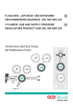
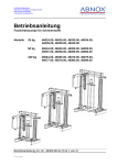
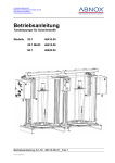
1
Druckminderer mit Schutzkasten
Typ PCV-DR, -DRS, -MV, -VCR, -H, -HS, -H-MV
Betriebsanleitung
Sprache:
Revision:
Stand:
Deutsch/Englisch
Version 1.1
April 2015
HINWEIS
Diese Betriebsanleitung ist vor der Montage, der Installation
und der Inbetriebnahme sorgfältig durchzulesen.
Diese Anleitung erhalten Sie auch in digitaler Form unter:
www.cgs-company.de/downloads/MDZ_M_B_PCV.pdf
MDZ_M_B_PCV_1.1
CGS ANALYSENTECHNIK
CGS PROZESSANALYTIK
Keltenstraße 3
D-85095 Denkendorf
Tel.: +49 8466 / 94 15 - 0
Fax: +49 8466 / 94 15 - 49
[email protected]
www.cgs-company.de
D
Produkt:
Druckminderer im Schutzkasten
Typ:
PCV-DR, -DRS, -MV, -VCR, -H, -HS, -H-MV
Revision 1.1 – Stand: April 2015
3/80
Inhaltsverzeichnis
D
Inhaltsverzeichnis . . . . . . . . . . . . . . . . . . . . . . . . . . . . . . . . . . . . . . . . . . . . . . . . . . . . . . . . . . . . . . . . . . . . 4
1 Allgemeine Hinweise . . . . . . . . . . . . . . . . . . . . . . . . . . . . . . . . . . . . . . . . . . . . . . . . . . . . . . . . . . . . . . . . 6
1.1 Geräteausführung und Gültigkeit . . . . . . . . . . . . . . . . . . . . . . . . . . . . . . . . . . . . . . . . . . . . . . . . . 6
1.2 Hinweise für unsere Kunden . . . . . . . . . . . . . . . . . . . . . . . . . . . . . . . . . . . . . . . . . . . . . . . . . . . . . 6
1.3 Allgemeines . . . . . . . . . . . . . . . . . . . . . . . . . . . . . . . . . . . . . . . . . . . . . . . . . . . . . . . . . . . . . . . . . 6
1.4 Warn- und Hinweistexte . . . . . . . . . . . . . . . . . . . . . . . . . . . . . . . . . . . . . . . . . . . . . . . . . . . . . . . . 6
1.5 Bestimmungsgemäßer Gebrauch . . . . . . . . . . . . . . . . . . . . . . . . . . . . . . . . . . . . . . . . . . . . . . . . . 7
1.6 Qualifiziertes Personal . . . . . . . . . . . . . . . . . . . . . . . . . . . . . . . . . . . . . . . . . . . . . . . . . . . . . . . . . 7
1.7 Hinweise zur Gewährleistung . . . . . . . . . . . . . . . . . . . . . . . . . . . . . . . . . . . . . . . . . . . . . . . . . . . . 7
1.8 Hinweise zur Lieferung . . . . . . . . . . . . . . . . . . . . . . . . . . . . . . . . . . . . . . . . . . . . . . . . . . . . . . . . . 8
1.9 Normen und Vorschriften . . . . . . . . . . . . . . . . . . . . . . . . . . . . . . . . . . . . . . . . . . . . . . . . . . . . . . . 8
1.10 Haftungsausschluss . . . . . . . . . . . . . . . . . . . . . . . . . . . . . . . . . . . . . . . . . . . . . . . . . . . . . . . . . . . 8
2 Warn- und Sicherheitshinweise . . . . . . . . . . . . . . . . . . . . . . . . . . . . . . . . . . . . . . . . . . . . . . . . . . . . . . . 10
3 Verpackung und Transport . . . . . . . . . . . . . . . . . . . . . . . . . . . . . . . . . . . . . . . . . . . . . . . . . . . . . . . . . . . 11
3.1 Verpackungsmaterial . . . . . . . . . . . . . . . . . . . . . . . . . . . . . . . . . . . . . . . . . . . . . . . . . . . . . . . . . . 11
3.2 Versand-Markierungen . . . . . . . . . . . . . . . . . . . . . . . . . . . . . . . . . . . . . . . . . . . . . . . . . . . . . . . . 11
3.3 Transportinspektion . . . . . . . . . . . . . . . . . . . . . . . . . . . . . . . . . . . . . . . . . . . . . . . . . . . . . . . . . . 12
3.4 Lagerung . . . . . . . . . . . . . . . . . . . . . . . . . . . . . . . . . . . . . . . . . . . . . . . . . . . . . . . . . . . . . . . . . . . 12
4 Installations-, Montagehinweis . . . . . . . . . . . . . . . . . . . . . . . . . . . . . . . . . . . . . . . . . . . . . . . . . . . . . . . 13
5 Druckregler . . . . . . . . . . . . . . . . . . . . . . . . . . . . . . . . . . . . . . . . . . . . . . . . . . . . . . . . . . . . . . . . . . . . . . . 14
5.1 Allgemeines . . . . . . . . . . . . . . . . . . . . . . . . . . . . . . . . . . . . . . . . . . . . . . . . . . . . . . . . . . . . . . . . 14
5.1.1. Vorbemerkung . . . . . . . . . . . . . . . . . . . . . . . . . . . . . . . . . . . . . . . . . . . . . . . . . . . . . . . . . 14
5.1.2 Geltungsbereich . . . . . . . . . . . . . . . . . . . . . . . . . . . . . . . . . . . . . . . . . . . . . . . . . . . . . . . . 14
5.2 Grundlegende Sicherheitshinweise . . . . . . . . . . . . . . . . . . . . . . . . . . . . . . . . . . . . . . . . . . . . . . 14
5.2.1 Hinweise in der Betriebsanleitung . . . . . . . . . . . . . . . . . . . . . . . . . . . . . . . . . . . . . . . . . 14
5.2.2 Verpflichtung des Betreibers . . . . . . . . . . . . . . . . . . . . . . . . . . . . . . . . . . . . . . . . . . . . . . 14
5.2.3 Verpflichtung des Personals . . . . . . . . . . . . . . . . . . . . . . . . . . . . . . . . . . . . . . . . . . . . . . 14
5.2.4 Gefahren im Umgang mit den druckführenden Geräten . . . . . . . . . . . . . . . . . . . . . . . . 15
5.2.5 Bestimmungsgemässe Verwendung . . . . . . . . . . . . . . . . . . . . . . . . . . . . . . . . . . . . . . . . 15
5.2.6 Gewährleistung und Haftung . . . . . . . . . . . . . . . . . . . . . . . . . . . . . . . . . . . . . . . . . . . . . 15
5.2.7 Organisatorische Massnahmen . . . . . . . . . . . . . . . . . . . . . . . . . . . . . . . . . . . . . . . . . . . . 15
5.2.8 Schutzeinrichtungen . . . . . . . . . . . . . . . . . . . . . . . . . . . . . . . . . . . . . . . . . . . . . . . . . . . . 16
5.2.9 Sicherheitsmassnahmen im Normalbetrieb . . . . . . . . . . . . . . . . . . . . . . . . . . . . . . . . . . 16
5.2.10 Gefahren durch Druckenergie . . . . . . . . . . . . . . . . . . . . . . . . . . . . . . . . . . . . . . . . . . . . 16
5.2.11 Gefahren durch elektrische Energie . . . . . . . . . . . . . . . . . . . . . . . . . . . . . . . . . . . . . . . . 16
5.2.12 Besondere Gefahren durch Leckage nach Aussen . . . . . . . . . . . . . . . . . . . . . . . . . . . . . 16
5.2.13 Hinweise zu speziellen Gasarten . . . . . . . . . . . . . . . . . . . . . . . . . . . . . . . . . . . . . . . . . . 16
5.2.14 Austreten schädlicher Gase und Dämpfe . . . . . . . . . . . . . . . . . . . . . . . . . . . . . . . . . . . . 17
5.2.15 Wartung und Instandhaltung, Störungsbeseitigung . . . . . . . . . . . . . . . . . . . . . . . . . . . 17
5.2.16 Bauliche Veränderungen am druckführenden Gerät . . . . . . . . . . . . . . . . . . . . . . . . . . . 17
5.2.17 Reinigen der Gasgeräte und Entsorgung der Rückstände . . . . . . . . . . . . . . . . . . . . . . . 17
5.2.18 Geräuschentwicklung. . . . . . . . . . . . . . . . . . . . . . . . . . . . . . . . . . . . . . . . . . . . . . . . . . . 17
6 Aufbau und Funktionshinweise . . . . . . . . . . . . . . . . . . . . . . . . . . . . . . . . . . . . . . . . . . . . . . . . . . . . . . . 18
6.1 Funktionsbeschreibung (Typ PCV-DR, PCV-DRS, PCV-MV) . . . . . . . . . . . . . . . . . . . . . . . . . . . . . . 18
6.1.1 Aufbau und Anschluss (Typ PCV-DR, PCV-DRS). . . . . . . . . . . . . . . . . . . . . . . . . . . . . . . . . 18
Produkt:
Druckminderer im Schutzkasten
Typ:
PCV-DR, -DRS, -MV, -VCR, -H, -HS, -H-MV
Revision 1.1 – Stand: April 2015
4/80
6.1.2 Aufbauzeichnung (Typ PCV-DR, PCV-DRS) . . . . . . . . . . . . . . . . . . . . . . . . . . . . . . . . . . . . 19
D
6.1.3 Aufbau und Anschluss (Typ PCV-MV) . . . . . . . . . . . . . . . . . . . . . . . . . . . . . . . . . . . . . . . . 20
6.1.4 Aufbauzeichnung (Typ PCV-MV) . . . . . . . . . . . . . . . . . . . . . . . . . . . . . . . . . . . . . . . . . . . . 21
6.2 Funktionsbeschreibung (Typ PCV-VCR) . . . . . . . . . . . . . . . . . . . . . . . . . . . . . . . . . . . . . . . . . . . . 22
6.2.1 Aufbau und Anschluss (Typ PCV-VCR) . . . . . . . . . . . . . . . . . . . . . . . . . . . . . . . . . . . . . . . 22
6.2.2 Aufbauzeichnung (Typ PCV-VCR) . . . . . . . . . . . . . . . . . . . . . . . . . . . . . . . . . . . . . . . . . . . 23
6.3 Funktionsbeschreibung (Typ PCV-H, PCV-HS) . . . . . . . . . . . . . . . . . . . . . . . . . . . . . . . . . . . . . . . 24
6.3.1 Aufbau und Anschluss (Typ PCV-H, PCV-HS) . . . . . . . . . . . . . . . . . . . . . . . . . . . . . . . . . . 24
6.3.2 Aufbauzeichnung (Typ PCV-H, PCV-HS) . . . . . . . . . . . . . . . . . . . . . . . . . . . . . . . . . . . . . . 25
6.3.3 Elektrischer Plan (Typ PCV-H, PCV-HS) . . . . . . . . . . . . . . . . . . . . . . . . . . . . . . . . . . . . . . . 26
6.4 Funktionsbeschreibung (Typ PCV-H-MV) . . . . . . . . . . . . . . . . . . . . . . . . . . . . . . . . . . . . . . . . . . . 27
6.4.1 Aufbau und Anschluss (Typ PCV-H-MV) . . . . . . . . . . . . . . . . . . . . . . . . . . . . . . . . . . . . . . 27
6.4.2 Aufbauzeichnung (Typ PCV-H-MV) . . . . . . . . . . . . . . . . . . . . . . . . . . . . . . . . . . . . . . . . . . 28
6.4.3 Elektrischer Plan (Typ PCV-H-MV) . . . . . . . . . . . . . . . . . . . . . . . . . . . . . . . . . . . . . . . . . . 29
7 Technische Daten . . . . . . . . . . . . . . . . . . . . . . . . . . . . . . . . . . . . . . . . . . . . . . . . . . . . . . . . . . . . . . . . . . 30
8 Reinigung . . . . . . . . . . . . . . . . . . . . . . . . . . . . . . . . . . . . . . . . . . . . . . . . . . . . . . . . . . . . . . . . . . . . . . . . 31
8.1 Oberfläche reinigen . . . . . . . . . . . . . . . . . . . . . . . . . . . . . . . . . . . . . . . . . . . . . . . . . . . . . . . . . . . 31
8.2 Innenraum reinigen . . . . . . . . . . . . . . . . . . . . . . . . . . . . . . . . . . . . . . . . . . . . . . . . . . . . . . . . . . 31
9 Ersatzteilliste & Bestellnummern . . . . . . . . . . . . . . . . . . . . . . . . . . . . . . . . . . . . . . . . . . . . . . . . . . . . . . 32
9.1 PCV-DR / PCV-DRS / PCV-MV . . . . . . . . . . . . . . . . . . . . . . . . . . . . . . . . . . . . . . . . . . . . . . . . . . . . 32
9.2 PCV-VCR . . . . . . . . . . . . . . . . . . . . . . . . . . . . . . . . . . . . . . . . . . . . . . . . . . . . . . . . . . . . . . . . . . . . 32
9.3 PCV-H / PCV-HS / PCV-H-MV . . . . . . . . . . . . . . . . . . . . . . . . . . . . . . . . . . . . . . . . . . . . . . . . . . . . 33
10 Lieferumfang . . . . . . . . . . . . . . . . . . . . . . . . . . . . . . . . . . . . . . . . . . . . . . . . . . . . . . . . . . . . . . . . . . . . 33
11 Anhang B (EG-Konformitätserklärung) . . . . . . . . . . . . . . . . . . . . . . . . . . . . . . . . . . . . . . . . . . . . . . . . . 34
12 Anhang C (Prüfprotokolle) . . . . . . . . . . . . . . . . . . . . . . . . . . . . . . . . . . . . . . . . . . . . . . . . . . . . . . . . . . 39
Produkt:
Druckminderer im Schutzkasten
Typ:
PCV-DR, -DRS, -MV, -VCR, -H, -HS, -H-MV
Revision 1.1 – Stand: April 2015
5/80
1 Allgemeine Hinweise
D
1.1 Geräteausführung und Gültigkeit
Diese Dokumentation ist zweckgebunden für das angegebene Produkt und trägt nur dafür seine Gültigkeit. Die Dokumentation beschreibt die Installation, die Inbetriebnahme und die Wartung und gibt
Auskunft über deren Funktion.
1.2 Hinweise für unsere Kunden
Lesen Sie vor Beginn der Arbeiten mit diesem Gerät unbedingt dieses Handbuch! Es enthält wichtige
Hinweise und Daten, deren Beachtung die Gerätefunktion sicherstellt und Ihnen Servicekosten erspart.
Der Umgang mit diesem Gerät wird Ihnen dadurch wesentlich erleichtert, führt Sie zu sicheren Messergebnissen und verhindert Schäden durch unsachgemäßen Gebrauch des Produktes.
1.3 Allgemeines
Dieses Gerät hat das Werk in einem sicherheitstechnisch einwandfreien und geprüften Zustand verlassen. Um diesen Zustand zu erhalten und um einen gefahrlosen Betrieb dieses Produkts sicherzustellen,
darf es nur in der vom Hersteller vorgeschriebenen Weise eingesetzt werden. Darüber hinaus setzt der
einwandfreie und sichere Betrieb dieses Produkts einen sachgemäßen Transport, fachgerechte Lagerung
und Aufstellung sowie sorgfältige Bedienung und Instandhaltung voraus.
Dieses Handbuch enthält die erforderlichen Informationen für den bestimmungsgemäßen Gebrauch des
darin beschriebenen Produkts.
Es wendet sich an technisch qualifiziertes Personal, das speziell ausgebildet ist, oder einschlägiges Wissen auf dem Gebiet der Automatisierungstechnik (Mess-, Steuerungs- und Regelungstechnik) besitzt.
Die Kenntnis und das technisch einwandfreie Umsetzen der in diesem Handbuch enthaltenen Sicherheitshinweise und Warnungen sind Voraussetzung für die gefahrlose Installation und Inbetriebnahme
sowie für die Sicherheit während des Betriebs und der Instandhaltung des beschriebenen Produkts. Nur
qualifiziertes Personal verfügt über das erforderliche Fachwissen, um die in diesem Handbuch in allgemein gültiger Weise gegebenen Sicherheitshinweise und Warnungen im konkreten Einzelfall richtig zu
interpretieren und in die Tat umzusetzen.
Dieses Handbuch ist fester Bestandteil des Lieferumfangs, auch wenn aus logistischen Gründen die Möglichkeit einer getrennten Bestellung vorgesehen wurde.
Aufgrund der Vielzahl an technischen Details ist es nicht möglich zu allen Ausführungen des beschriebenen Produkts und zu jedem erdenklichen Fall der Aufstellung, des Betriebs, der Instandhaltung und des
Einsatzes in Systemen, sämtliche Einzelheiten zu berücksichtigen.
Sollten Sie weitere Informationen benötigen, oder sollten Probleme auftreten, die in dieser Unterlage
nicht ausführlich genug behandelt werden, dann fordern Sie bitte die benötigte Auskunft von Ihrer örtlichen bzw. zuständigen CGS Vertretung an.
1.4 Warn- und Hinweistexte
In diesem Handbuch wird beschrieben, wie Sie dieses Gerät bestimmungsgemäß betreiben, in Betrieb
nehmen, bedienen und Instand halten können.
Besonders beachten müssen Sie dabei Warn- und Hinweistexte. Diese sind vom übrigen Text abgesetzt
und durch entsprechende Piktogramme besonders gekennzeichnet. Sie liefern Ihnen wertvolle Tipps zur
Vermeidung von Fehlbedienung und Unfällen.
Produkt:
Druckminderer im Schutzkasten
Typ:
PCV-DR, -DRS, -MV, -VCR, -H, -HS, -H-MV
Revision 1.1 – Stand: April 2015
6/80
1.5 Bestimmungsgemäßer Gebrauch
D
Ein bestimmungsgemäßer Gebrauch im Sinne dieses Handbuchs bedeutet, dass dieses Produkt nur für
die im Katalog und in der technischen Beschreibung vorgesehenen Einsatzfälle und nur in Verbindung
mit von CGS empfohlenen bzw. zugelassenen Fremdgeräten und -komponenten verwendet werden darf.
Das in diesem Handbuch beschriebene Produkt ist unter Beachtung der einschlägigen Sicherheitsnormen entwickelt, gefertigt, geprüft und dokumentiert worden. Bei Beachtung der für die Projektierung,
die Montage, den bestimmungsgemäßen Betrieb und die Instandhaltung beschriebenen Hantierungsvorschriften und sicherheitstechnischen Hinweise gehen deshalb im Normalfall keine Gefahren für die
Gesundheit von Personen oder in Bezug auf Sachschäden aus.
1.6 Qualifiziertes Personal
Qualifiziert sind Personen, die mit der Aufstellung, der Montage, der Inbetriebsetzung und dem Betrieb
des Produkts vertraut sind.
Diese Personen verfügen über folgende Qualifikationen:
• Sie sind berechtigt und ausgebildet bzw. unterwiesen, Geräte und Systeme gemäß den Standards der
Sicherheitstechnik für elektrische Stromkreise, hohe Drücke und aggressive sowie gefährliche Medien
zu betreiben und zu warten.
• Bei Geräten mit Explosionsschutz: Sie sind berechtigt und ausgebildet bzw. unterwiesen, Arbeiten an
elektrischen Stromkreisen für explosionsgefährdete Anlagen durchzuführen.
• Sie sind in der Pflege und dem Gebrauch angemessener Sicherheitsausrüstung, gemäß den Standards
der Sicherheitstechnik ausgebildet bzw. unterwiesen.
1.7 Hinweise zur Gewährleistung
Der Inhalt dieser Anleitung ist weder Teil einer früheren oder bestehenden Vereinbarung, einer Zusage oder eines früheren oder bestehenden Rechtsverhältnisses, noch soll er diese abändern. Sämtliche
Verpflichtungen der CGS ergeben sich aus dem jeweiligen Kaufvertrag, der auch die vollständige und
alleingültige Gewährleistungsregelung enthält.
Diese vertraglichen Gewährleistungsbestimmungen werden durch die Ausführungen der Anleitung weder erweitert noch beschränkt.
Für Schäden und Betriebsstörungen, die sich aus der Nichtbeachtung der Betriebsanleitung ergeben,
übernimmt der Hersteller keine Haftung.
Neben der Betriebsanleitung und den im Verwenderland und an der Einsatzstelle geltenden verbindlichen Regelungen zur Unfallverhütung sind auch die anerkannten fachtechnischen Regeln für sicherheitsund fachgerechtes Arbeiten zu beachten.
Der Gewährleistungsanspruch erlischt, wenn das Gerät nicht vorschriftsgemäß montiert, in Betrieb genommen und betrieben wird.
Produkt:
Druckminderer im Schutzkasten
Typ:
PCV-DR, -DRS, -MV, -VCR, -H, -HS, -H-MV
Revision 1.1 – Stand: April 2015
7/80
D
Die Gewährleistung erlischt des Weiteren bei:
• Sachwidriger Verwendung
• Verwendung unzulässiger Betriebsmittel
• Fehlerhaftem Anschluss und Vorgewerken, die nicht zum Liefer– und Leistungsumfang gehören
• Nichtverwendung von Originalersatz– und Zubehörteilen
• Umrüstungen, die nicht durch CGS selbst vorgenommen wurden
• Nichtdurchführung vorgeschriebener Instandhaltungsarbeiten
Der Inhalt spiegelt den technischen Stand zum Zeitpunkt der Veröffentlichung wieder.
Technische Änderungen sind im Zuge der Weiterentwicklung vorbehalten.
1.8 Hinweise zur Lieferung
Der jeweilige Lieferumfang ist entsprechend dem gültigen Kaufvertrag, in den der Lieferung beigefügten Versandpapieren aufgeführt.
Beim Öffnen der Verpackung beachten Sie bitte die entsprechenden Hinweise auf dem Verpackungsmaterial. Prüfen Sie die Lieferung auf Vollständigkeit und Unversehrtheit. Insbesondere sollten Sie, soweit
vorhanden, die Bestellnummer auf den Typenschildern mit den Bestelldaten vergleichen.
Wenn möglich, bewahren Sie bitte das Verpackungsmaterial auf, da Sie dieses für eventuelle Rücklieferungen wieder verwenden können (siehe Kapitel: Verpackung und Transport).
1.9 Normen und Vorschriften
Soweit möglich wurden für die Spezifikation und die Produktion dieses Geräts die harmonisierten europäischen Normen zugrunde gelegt. Sofern keine harmonisierten europäischen Normen angewandt
wurden, gelten die Normen und Vorschriften der Bundesrepublik Deutschland.
Bei einem Einsatz dieses Produkts außerhalb des Geltungsbereichs dieser Normen und Vorschriften, sind
die im Land des Betreibers gültigen Normen und Vorschriften zu beachten.
1.10 Haftungsausschluss
Sämtliche in dieser Betriebsanleitung enthaltenen technischen Informationen, Daten und Hinweise für
den Betrieb, entsprechen dem letzten Stand bei Erstellung dieses Handbuches und erfolgen unter Berücksichtigung unserer bisherigen Erfahrung und Erkenntnisse nach bestem Wissen.
Technische Änderungen im Rahmen der Weiterentwicklung des in dieser Betriebsanleitung behandelten
Gerätes, behalten wir uns vor. Aus den Angaben, den Abbildungen und den Beschreibungen dieser Betriebsanleitung können keine Ansprüche hergeleitet werden.
Für Schäden und Betriebsstörungen, die durch Bedienungsfehler, Nichtbeachtung dieser Betriebsanleitung oder unsachgemäße Reparaturen entstehen, übernehmen wir keine Haftung.
Wir weisen ausdrücklich darauf hin, dass nur von uns freigegebene Originalersatz- und Zubehörteile
eingesetzt werden dürfen. Dies gilt sinngemäß auch für eingesetzte Baugruppen anderer Hersteller.
Produkt:
Druckminderer im Schutzkasten
Typ:
PCV-DR, -DRS, -MV, -VCR, -H, -HS, -H-MV
Revision 1.1 – Stand: April 2015
8/80
Der Einbau bzw. die Verwendung von nicht freigegebenen Ersatz- und Zubehörteilen und jegliche ei-
D
genmächtigen Umbauten und Veränderungen sind aus Sicherheitsgründen nicht gestattet und schließen
eine Haftung der CGS für hieraus resultierende Schäden aus.
Ansprüche auf Schadenersatz, gleich aus welchem Rechtsgrund sie hergeleitet werden, sind ausgeschlossen.
Übersetzungen werden nach bestem Wissen durchgeführt. Eine Haftung für Übersetzungsfehler können
wir nicht übernehmen, auch dann nicht, wenn die Übersetzung von uns oder in unserem Auftrag erfolgte. Verbindlich bleibt allein der ursprüngliche Text.
Die textlichen und zeichnerischen Darstellungen entsprechen nicht unbedingt dem Lieferumfang bzw.
einer eventuellen Ersatzteilbestellung.
Die Zeichnungen und Grafiken sind nicht maßstäblich.
Produkt:
Druckminderer im Schutzkasten
Typ:
PCV-DR, -DRS, -MV, -VCR, -H, -HS, -H-MV
Revision 1.1 – Stand: April 2015
9/80
2 Warn- und Sicherheitshinweise
D
Dieses Handbuch enthält wichtige Warn- und Sicherheitshinweise, die Sie zu Ihrer persönlichen Sicherheit, sowie zur Vermeidung von Sachschäden beachten müssen. Die Hinweise zu Ihrer persönlichen
Sicherheit sind durch ein Warndreieck hervorgehoben, Hinweise zu alleinigen Sachschäden stehen ohne
Warndreieck. Je nach Gefährdungsstufe werden die Warnhinweise in abnehmender Reihenfolge wie
folgt dargestellt.
GEFAHR
bedeutet, dass Tod oder schwere Körperverletzung eintreten wird, wenn die entsprechenden
Vorsichtsmaßnahmen nicht getroffen werden.
WARNUNG
bedeutet, dass Tod oder schwere Körperverletzung eintreten kann, wenn die entsprechenden
Vorsichtsmaßnahmen nicht getroffen werden.
VORSICHT
mit Warndreieck bedeutet, dass leichte Körperverletzung eintreten kann, wenn die entsprechenden
Vorsichtsmaßnahmen nicht getroffen werden.
VORSICHT
ohne Warndreieck bedeutet, dass Sachschaden eintreten kann, wenn die entsprechenden Vorsichtsmaßnahmen nicht getroffen werden.
HINWEIS
bedeutet, dass ein unerwünschtes Ereignis oder Zustand eintreten kann, wenn der entsprechende
Hinweis nicht beachtet wird.
Beim Auftreten mehrerer Gefährdungsstufen wird immer der Warnhinweis zur jeweils höchsten Stufe
verwendet. Wenn in einem Warnhinweis mit dem Warndreieck vor Personenschäden gewarnt wird, dann
kann im selben Warnhinweis zusätzlich eine Warnung vor Sachschäden angefügt sein.
Produkt:
Druckminderer im Schutzkasten
Typ:
PCV-DR, -DRS, -MV, -VCR, -H, -HS, -H-MV
Revision 1.1 – Stand: April 2015
10/80
3 Verpackung und Transport
3.1 Verpackungsmaterial
D
Die einzelnen Anlagenteile und Module gelangen in unterschiedlichen Verpackungen zum Versand. Vorwiegende Verpackungsmaterialien sind Holz, Pappe und Kunststoffe (Folien, Schaumstoffe) aber auch
u. a. Bandeisen (für Bunde). Zum Verpackungsmaterial gehören auch Materialien, die den Packstücken
zum Feuchtigkeitsschutz beigegeben werden (z.B. Kieselgelbeutel).
Wenn keine entsprechende Vereinbarung über Rücknahme des Verpackungsmaterials getroffen wurde,
verbleibt das Verpackungsmaterial beim Kunden.
Eine umweltgerechte und in Übereinstimmung mit den entsprechenden Entsorgungsvorschriften stehende Beseitigung muss gewährleistet sein. Beauftragen Sie gegebenenfalls Entsorungsunternehmen mit
der Entsorgung des Verpackungsmaterials.
Die Anlagenteile sind nach Möglichkeit in der Verpackung zum Montageort zu transportieren und bis zur
Montage in der Verpackung zu lassen.
3.2 Versand-Markierungen
Auf den Packstücken sind Symbole angebracht, die in allen Phasen des Transports und der Lagerung zu
beachten sind.
1. OBEN! Das Packstück muss grundsätzlich so transportiert, umgeschlagen und gelagert werden, dass
die Pfeile jederzeit nach oben zeigen. Rollen, Klappen, starkes Kippen oder Kanten sowie andere Formen
des Handlings müssen unterlassen werden.
2. Gabelstapler hier nicht ansetzen.
3. Sperrschicht nicht beschädigen.
4. Zerbrechliches Packgut! Derartig gekennzeichnete Waren sind sorgfältig zu behandeln und keineswegs
zu stürzen oder zu schnüren.
5. Vor Nässe schützen. Derartig gekennzeichnete Waren sind vor zu hoher Feuchtigkeit zu schützen. Sie
müssen daher gedeckt gelagert werden.
6. Schwerpunkt. Durch dieses Zeichen soll die Lage des Schwerpunktes eindeutig gekennzeichnet werden.
Produkt:
Druckminderer im Schutzkasten
Typ:
PCV-DR, -DRS, -MV, -VCR, -H, -HS, -H-MV
Revision 1.1 – Stand: April 2015
11/80
3.3 Transportinspektion
Wichtig:
D
Überprüfen Sie sofort nach dem Eintreffen die gesamte Lieferung auf Vollständigkeit und eventuelle
Transportschäden.
Bei Nichtbeachtung der folgenden Anweisungen für den Schadensfall kann die Leistungspflicht des Versicherers entfallen.
• Schon bei Verdacht eines Schadens: Quittieren Sie den Empfang nur unter Vorbehalt (z.B. auch Frachtdokument) mit Angabe des vermuteten Schadens.
• Stellen Sie Ersatzansprüche gegen Dritte sicher:
Beförderer, Spediteure, Lagerhalter:
- zu gemeinsamer Schadensbesichtigung auffordern
- um Bescheinigung des Schadens ersuchen
- schriftlich haftbar machen und den Schaden detailliert beschreiben,
und zwar:
- bei äußerlich erkennbaren Schäden vor Abnahme des Gutes
- bei äußerlich nicht erkennbaren Schäden unverzüglich nach Entdeckung
• Stellen Sie Reklamationsfristen fest und halten Sie diese ein!
• Sorgen Sie für Minderung entstandener und Abwendung weiterer Schäden.
• Ziehen Sie unverzüglich den in den Versicherungsunterlagen genannten Havariekommissar hinzu, der
den Schaden feststellt und Rat für die Sicherung der Ersatzansprüche gegenüber Dritten und für Maßnahmen der Schadensminderung erteilt.
• Verändern Sie keinesfalls den Zustand der Sendung und ihrer Verpackung bis zum Eintreffen des Havariekommissars, soweit dies nicht zur Minderung und Abwendung weiteren Schadens erforderlich ist.
• Zeigen Sie den Versicherungsfall dem Versicherer unverzüglich an und übermitteln zur Beschleunigung
der Schadensabwicklung alsbald vollständige Schadensunterlagen (spätestens jedoch rechtzeitig vor
Ablauf eventueller Ausschluss- und/oder Verjährungsfristen für Ersatzasprüche gegen Dritte).
3.4 Lagerung
Nach dem Abladen müssen die Packstücke bis zur Montage unter Beachtung der Versand-Markierungen
gelagert werden.
Verpackte Maschinenteile und Zubehör dürfen nicht ausgepackt werden.
Beachten Sie die für die Lagerung geltenden Vorschriften:
• Trocken lagern. Maximale Luftfeuchtigkeit: 60 %.
• Es ist dafür zu sorgen, dass die Packstücke nicht im Freien lagern.
• Darüber hinaus muss gewährleistet sein, dass der Boden des Lagerraums während
• der Lagerung trocken ist.
• Vor direkter Sonneneinstrahlung schützen. Lagertemperatur 5°C bis 35°C.
• Staubfrei lagern!
• Mechanische Erschütterungen und Beschädigungen vermeiden.
• Bei längerer Lagerung über ca. 3 Monate sind die Konservierungsmaßnahmen zu überprüfen.
• Bei aggressiven Witterungsverhältnissen muss die Konservierung ggf. erneuert werden.
Produkt:
Druckminderer im Schutzkasten
Typ:
PCV-DR, -DRS, -MV, -VCR, -H, -HS, -H-MV
Revision 1.1 – Stand: April 2015
12/80
4 Installations-, Montagehinweis
Sicherheitsmaßnahmen:
Die Installation und Montage darf nur von speziell ausgebildetem und qualifiziertem Fachpersonal durch-
D
geführt werden. Dabei sind die allgemein gültigen Unfallverhütungsvorschriften zu beachten.
Bei Inbetriebnahme durch die CGS bzw. dazu beauftragter Firmen erfolgt eine formale Übergabe an den
Betreiber. Danach kann das Gerät unter Beachtung der Angaben der Bedienungsanleitung und den
gültigen Sicherheitsvorschriften bestimmungsgemäß betrieben werden.
Vor dem Öffnen des Geräts ist es in jedem Falle vom Stromnetz zu trennen.
WARNUNG
Aus Gründen des Personenschutzes ist die kundenseitige Installation eines
Fehlerstromschutzschalters in der Spannungsversorgung empfohlen.
Anforderungen an den Aufstellungsort:
• Keine direkte Sonneneinstrahlung
• Geringe Staubbelastung
• Ausreichender Freiraum für den Betrieb und zur Wartung
• Fluchtwege vorhanden und frei zugänglich
• Keine Stolpergefährdung durch bodennah verlaufende Leitungen, etc.
• Maximale Höhe: 2000 m über Meeresspiegel
Technische Daten (elektrische Anschlusswerte, Gasdrücke, etc.) finden Sie im Abschnitt Technische Daten.
Produkt:
Druckminderer im Schutzkasten
Typ:
PCV-DR, -DRS, -MV, -VCR, -H, -HS, -H-MV
Revision 1.1 – Stand: April 2015
13/80
5 Druckregler
D
5.1 Allgemeines
5.1.1. Vorbemerkung
Diese Armaturen sind Präzisionsinstrumente von höchster Qualität. Durch die Verwendung ausgewählter
Materialien, durch hohe Oberflächengüte und Dichtheit lassen sich Druck und Durchfluß auch von reinsten
Gasen ohne Beeinträchtigung der Reinheit präzise mit gleichbleibender Genauigkeit regeln. Alle Schritte
- von der Konzeption, über die Fertigung bis zur Endkontrolle - unterliegen den strengen Kriterien unserer
Qualitätssicherung nach DIN EN ISO 9001.
5.1.2 Geltungsbereich
Diese Betriebsanleitung gilt ausschließlich für druckführende Geräte des Herstellers (siehe Typenschild).
Die Produkte sind durch Typenschilder, Herstellerangabe an den Bedienelementen oder Aufdrucke an
druckführenden Teilen gekennzeichnet. Reinstgassysteme in diesem Sinne sind Behälter, Rohrleitungen,
Baugruppen und Ausrüstungsteile wie Druckminderer, Ventile, Berstscheiben und andere.
Diese druckführenden Geräte können auch in Anlagen integriert sein. Es gelten dann entsprechende
anlagenspezifische Betriebsanleitungen zusammen mit dieser Betriebsanleitung.
5.2 Grundlegende Sicherheitshinweise
5.2.1 Hinweise in der Betriebsanleitung
Diese Betriebsanleitung enthält die wichtigsten Hinweise, um druckführende Geräte sicherheitsgerecht
zu betreiben. Die Sicherheitshinweise sind von allen Personen zu beachten,die an den Armaturen
arbeiten.
Darüberhinaus sind die für den Einsatzort geltenden Regeln und Vorschriften zur Unfallverhütung zu
beachten.
5.2.2 Verpflichtung des Betreibers
Der Betreiber verpflichtet sich, nur Personen an druckführenden Geräten arbeiten zu lassen, die
• mit den grundlegenden Vorschriften über Arbeitssicherheit und Unfallverhütung vertraut sind und
andauernd Zugang zu diesen Vorschriften haben,
• das Sicherheitskapitel und die Warnhinweise in dieser Betriebsanleitung gelesen und verstanden haben
und
• geschult und an druckführenden Geräten eingewiesen sind.
• Das sicherheitsbewußte Arbeiten des Personals wird in regelmäßigen Abständen überprüft.
• Die Zuständigkeiten des Personals für das Montieren, Inbetriebnehmen und Bedienen sind klar
festzulegen.
• Anzulernendes Personal darf nur unter Aufsicht einer erfahrenen Person an druckführenden Geräten
arbeiten.
• Alle Sicherheits- und Gefahrenhinweise sind stets in lesbarem Zustand zu halten.
5.2.3 Verpflichtung des Personals
Alle Personen, die mit Arbeiten an druckführenden Geräten beauftragt sind, verpflichten sich
vor Arbeitsbeginn
• die grundlegenden Vorschriften über Arbeitssicherheit und Unfallverhütung zu beachten,
• sich mit dem Sicherheitsdatenblatt der verwendeten Gasart vertraut zu machen.
Produkt:
Druckminderer im Schutzkasten
Typ:
PCV-DR, -DRS, -MV, -VCR, -H, -HS, -H-MV
Revision 1.1 – Stand: April 2015
14/80
5.2.4 Gefahren im Umgang mit den druckführenden Geräten
Flaschen-, Leitungs- oder Entnahmedruckminderer (im weiteren als druckführende Geräte bezeichnet)
sind nach dem Stand der Technik und den anerkannten sicherheitstechnischen Regeln gebaut. Dennoch
D
können bei ihrer Verwendung Gefahren für Leib und Leben des Benutzers oder Dritter bzw. Beeinträchtigungen am druckführenden Geräten oder an anderen Sachwerten entstehen.
• Das druckführenden Geräten ist nur für die bestimmungsgemäße Verwendung zu benutzen.
• Störungen, die die Sicherheit beeinträchtigen können, sind umgehend zu beseitigen.
5.2.5 Bestimmungsgemässe Verwendung
Das druckführende Geräte ist ausschließlich zur Entspannung von gasförmigen Medien aus
Druckgasbehältern bestimmt. Eine andere oder darüber hinausgehende Benutzung gilt als nicht
bestimmungsgemäß. Zur bestimmungsgemäßen Verwendung gehört auch:
• das Beachten aller Hinweise aus der Betriebsanleitung,
• die Einhaltung der Inspektions- und Wartungsarbeiten,
• das Beachten des Typenschildes und der Datenblätter.
5.2.6 Gewährleistung und Haftung
Grundsätzlich gelten unsere „Allgemeinen Verkaufsund Lieferbedingungen”. Diese stehen dem Betreiber
spätestens seit Vertragsabschluß zur Verfügung. Gewährleistungs- und Haftungsansprüche bei Personen
und Sachschäden sind ausgeschlossen, wenn sie auf eine oder mehrere der folgenden Ursachen
zurückzuführen sind:
• Nicht bestimmungsgemäße Verwendung des druckführenden Gerätes.
• Unsachgemäßes Montieren, Inbetriebnehmen, Bedienen und Warten des druckführenden Gerätes.
• Betreiben des druckführenden Gerätes bei defekten Sicherheitseinrichtungen oder nicht ordnungsgemäß angebrachten oder nicht funktionsfähigen Sicherheits- und Schutzvorrichtungen.
• Nichtbeachten der Hinweise in der Betriebsanleitung bezüglich Transport, Lagerung, Montage,
Inbetriebnahme, Betrieb, Wartung und Rüsten des druckführenden Gerätes.
• Eigenmächtige bauliche Veränderungen am druckführenden Gerät.
• Eigenmächtiges Verändern der Flaschenanschlüsse zur Verwendung anderer Gasarten, der
Überschreitung der zulässigen Eingangsdrücke, der Verwendung fremder bzw. nicht originaler
Dichtungen.
• Mangelhafte Überwachung von Ausrüstungs-, Verschraubungs- und Dichtungsteilen, die einem
Verschleiß unterliegen.
• Unsachgemäß durchgeführte Reparaturen.
• Überschreitung oder Unterschreitung des im Datenblatt angegebenen Temperaturbereichs während des
Betriebs bzw. während der Lagerung.
• Katastrophenfälle durch Fremdkörpereinwirkung und höhere Gewalt.
5.2.7 Organisatorische Massnahmen
• Die erforderlichen persönlichen Schutzausrüstungen sind vom Betreiber bereitzustellen.
• Alle vorhandenen Sicherheitseinrichtungen sind regelmäßig zu überprüfen.
• Bei Sauerstoffmangel oder zu hoher Schadstoffkonzentration sind von der Umgebungsatmosphäre
unabhängige Atemschutzgeräte erforderlich.
Produkt:
Druckminderer im Schutzkasten
Typ:
PCV-DR, -DRS, -MV, -VCR, -H, -HS, -H-MV
Revision 1.1 – Stand: April 2015
15/80
5.2.8 Schutzeinrichtungen
• Vor jeder Inbetriebnahme des druckführenden Gerätes müssen alle Sicherheitseinrichtungen
sachgerecht angebracht und funktionsfähig sein.
D
• Schutzvorrichtungen und Sicherheitseinrichtungen dürfen nur nach Außerbetriebsetzen des
druckführenden Gerätes bzw. der Anlage und Absicherung gegen Wiederinbetriebnahme des
druckführenden Gerätes entfernt werden.
• Bei Lieferung von Teilkomponenten sind die Sicherheitseinrichtungen durch den Betreiber
vorschriftsmäßig anzubringen.
5.2.9 Sicherheitsmassnahmen im Normalbetrieb
• Vor Einschalten des druckführenden Gerätes sicherstellen, daß niemand durch das Inbetriebnehmen
des druckführenden Gerätes gefährdet werden kann.
• Mindestens einmal pro Jahr das druckführende Gerät auf Dichtheit und Funktionsfähigkeit der
Sicherheitseinrichtungen überprüfen.
5.2.10 Gefahren durch Druckenergie
• Zu öffnende Systemabschnitte und Druckleitungen vor Beginn von Reparaturarbeiten drucklos machen.
• Durch äußere Einwirkungen wie hohe Temperaturen, Wärmestrahlung, Stoß und ähnliches können sich
Druckgasflaschen oder unter Druck stehende Anlagenteile stark erwärmen bzw. bersten. Treffen Sie bitte
entsprechende Vorsichts- und Sicherheitsmaßnahmen.
5.2.11 Gefahren durch elektrische Energie
• Arbeiten an elektrischen Bauteilen, Anzeige- und Steuerungseinheiten (z.B. Gasmangelanzeige) nur
von einer Elektro-Fachkraft ausführen lassen.
• Die elektrische Ausrüstung der Anlage regelmäßig überprüfen. Lose Verbindungen und beschädigte
Kabel sofort beseitigen.
• Der Schaltschrank bzw. die elektrischen Baugruppen sind stets verschlossen zu halten. Der Zugang ist
nur autorisiertem Personal mit Schlüssel oder Werkzeug erlaubt.
5.2.12 Besondere Gefahren durch Leckage nach Aussen
• Durch die Verwendung von sehr gefährlichen, gefährlichen oder weniger gefährlichen Gasen können
bei Undichtigkeit des druckführenden Gerätes Gefahren für Leib und Leben des Benutzers entstehen.
• Deshalb ist eine Betriebsanweisung gemäß § 20 GefStoffV, ein aktuelles EU-Sicherheitsdatenblatt nach
§ 14 GefStoffV und ein Unfallmerkblatt mit Hinweisen für den Arzt an geeigneter Stelle vorzuhalten.
• Die Bediener sind auf die besonderen Gefahren des Gases und auf eventuelle Personen- und andere
Schutzmaßnahmen hinzuweisen.
5.2.13 Hinweise zu speziellen Gasarten
• Alle mit Sauerstoff in Berührung kommenden Teile müssen absolut öl- und fettfrei sein, Brandund
Explosionsgefahr!
• Nur Schmierstoffe mit Sauerstoffzulassung verwenden.
• Bei Acetylen keine Rohrleitungen oder andere Anlagenteile aus Kupfer verwenden! Besondere
Gefährdungspotentiale des Acetylens beachten!
• Für korrosive, reaktive oder brennbare Gasgemische spezielle Druckminderer, wie z. B. den FMD
500/502-21, verwenden.
Produkt:
Druckminderer im Schutzkasten
Typ:
PCV-DR, -DRS, -MV, -VCR, -H, -HS, -H-MV
Revision 1.1 – Stand: April 2015
16/80
5.2.14 Austreten schädlicher Gase und Dämpfe
• Bei geöffneten Sicherheitseinrichtungen oder Störfällen können schädliche Gase und Dämpfe
entweichen (s. o.). Für ausreichend Entlüftung oder Absaugung sorgen.
D
• Bei gefährlichen Medien besondere Schutzvorkehrungen treffen. Insbesondere die Ausgänge der
Abblase- und Spülventile über feste Rohrleitungen ableiten und die Stoffe sicherheitsgerecht und
umweltverträglich entsorgen.
5.2.15 Wartung und Instandhaltung, Störungsbeseitigung
• Vorgeschriebene Einstell-, Wartungs- und Inspektionsarbeiten fristgemäß durch den Hersteller oder
durch vom Hersteller autorisierte Fachbetriebe durchführen lassen.
• Bedienungspersonal und Nutzer vor Beginn der Wartungs- und Instandhaltungsarbeiten informieren.
• Alle zur Ansteuerung der druckführenden Geräte bzw. der Anlage vor- und nachgeschalteten
Betriebsmedien wie Druckluft und Hydraulik gegen unbeabsichtigte Inbetriebnahme absichern.
• Bei allen Wartungs-, Inspektions- und Reparaturarbeiten die zugehörigen Betriebsmittel spannungsfrei
schalten und Hauptschalter gegen unerwartetes Wiedereinschalten sichern.
• Hauptschalter abschließen und Schlüssel abziehen.
• Ein Warnschild gegen Wiedereinschalten anbringen.
• Gelöste Schraubverbindungen auf festen Sitz kontrollieren.
• Nach Beendigung der Wartungsarbeiten Sicherheitseinrichtungen auf Funktion überprüfen.
5.2.16 Bauliche Veränderungen am druckführenden Gerät
• Ohne schriftliche Genehmigung des Herstellers keine Veränderungen, An- oder Umbauten am
druckführenden Gerät oder der Anlage vornehmen.
• Anlagenteile in nicht einwandfreiem Zustand sofort austauschen.
• Nur Original-Ersatz- und Verschleißteile des Herstellers verwenden.
• Das Wechseln der Flaschenanschlußteile oder die Verwendung von Übergangsstücken für
unterschiedliche Anschlüsse nach DIN 477 ist untersagt (Geräteschutzgesetz)!
5.2.17 Reinigen der Gasgeräte und Entsorgung der Rückstände
• Durch die Verwendung von sehr gefährlichen, gefährlichen oder weniger gefährlichen Gasen können
bei Undichtigkeit des druckführenden Gerätes Gefahren für Leib und Leben des Benutzers entstehen.
5.2.18 Geräuschentwicklung
In einigen Fällen kann das ungünstige Zusammenwirken bestimmter Einflußgrößen, wie z. B. Durchfluß
und Druckbereich, aber auch die Gasart selbst zu Geräuschentwicklungen führen. Bitte setzen Sie sich in
solchen Fällen mit dem Hersteller in Verbindung.
Produkt:
Druckminderer im Schutzkasten
Typ:
PCV-DR, -DRS, -MV, -VCR, -H, -HS, -H-MV
Revision 1.1 – Stand: April 2015
17/80
6 Aufbau und Funktionshinweise
6.1 Funktionsbeschreibung (Typ PCV-DR, PCV-DRS, PCV-MV)
D
Der Druckregler im Schutzschrank dient zur Druckreduzierung gasförmiger Medien. Er wird direkt an
der Proben-Entnahmestelle eingebaut. Der Schutzkasten wird mittels Wandbefestigungsset montiert. Das Medium wird an der Schottverschraubung angeschlossen. Je nach Spezifikation wird eine
6mm bzw. 1/4“ Verschraubung aufgerüstet. Der Druckregler wird von einem Filter geschützt. Die Filterfeinheit beträgt 100 μm. Der Druckregler entspannt den Prozessdruck von max. 230 bar entsprechend dem benötigten Betriebsdruck der nachfolgenden gasführenden Bauteilen, z.B. 0,5 - 6 bar.
Der Mediumausgang ist ebenfalls wie der Eingang mit einer 6mm bzw. 1/4“ Schottverschraubung
bestückt. Durch das auf der Unterseite befindliche Druckausgleichselement kann der bei überströmendem Gas entstehende Druck im Gehäuse entweichen.
Nur Typ PCV-MV:
Das eingebaute 2/2-Wege Magnetventil dient zur Abschaltung im Fehlerfall. Der elektr. Anschluss
wird je nach Bedarf mit 24VDC, 115VAC oder 230VAC ausgeführt.
6.1.1 Aufbau und Anschluss (Typ PCV-DR, PCV-DRS)
Manometer
Druckregler
Filtervlies
100 μm
Abblaseventil
Wandbefestigung
OUT
Druckausgleichs-
IN
Potentialausgleich
element
Beim Anschluss an den Druckregler ist darauf zu achten, dass sich dieser im drucklosen Zustand befindet.
Hierzu wird der Druckregler in die linke Stellung (-) gebracht.
Die Lochabstands-Maße zur Wandbefestigung des Kastens entnehmen Sie dem Kapitel Aufbauzeichnung.
Produkt:
Druckminderer im Schutzkasten
Typ:
PCV-DR, -DRS, -MV, -VCR, -H, -HS, -H-MV
Revision 1.1 – Stand: April 2015
18/80
inlet
outlet
filter
D
+
80
60
200
126
www.cgs-company.de
30
75
150
191
-
mounting plate
Montageplatte
gas ussdiagramm
flow diagram
Gasfl
6.1.2 Aufbauzeichnung (Typ PCV-DR, PCV-DRS)
300
320
Produkt:
Druckminderer im Schutzkasten
Typ:
PCV-DR, -DRS, -MV, -VCR, -H, -HS, -H-MV
Revision 1.1 – Stand: April 2015
19/80
6.1.3 Aufbau und Anschluss (Typ PCV-MV)
D
Manometer
Druckregler
Filtervlies
100 μm
Abblaseventil
Magnetventil
Wandbefestigung
OUT
Druckausgleichselement
IN
Potentialausgleich
Kabelverschraubung
für Magnetventil
Beim Anschluss an den Druckregler ist darauf zu achten, dass sich dieser im drucklosen Zustand befindet.
Hierzu wird der Druckregler in die linke Stellung (-) gebracht.
Das Anschlusskabel des Magnetventils kann über die Kabelverschraubung aus dem Gehäuse geführt
werden.
Die Lochabstands-Maße zur Wandbefestigung des Kastens entnehmen Sie dem Kapitel Aufbauzeichnung.
Produkt:
Druckminderer im Schutzkasten
Typ:
PCV-DR, -DRS, -MV, -VCR, -H, -HS, -H-MV
Revision 1.1 – Stand: April 2015
20/80
6.1.4 Aufbauzeichnung (Typ PCV-MV)
inlet
outlet
filter
+
150
80
60
200
126
www.cgs-company.de
30
75
191
-
Montageplatte
Gasflussdiagramm
D
300
320
Produkt:
Druckminderer im Schutzkasten
Typ:
PCV-DR, -DRS, -MV, -VCR, -H, -HS, -H-MV
Revision 1.1 – Stand: April 2015
21/80
6.2 Funktionsbeschreibung (Typ PCV-VCR)
Der Druckregler im Schutzschrank für Hochreinanwendung dient zur Reduzierung gasförmiger Medien.
D
Der Druckregler im Schutzschrank wird direkt an der Proben-Entnahmestelle eingebaut. Der Schutzkasten wird mittels Wandbefestigungsset montiert. Das Medium wird an der 1/4“-VCR Schottverschraubung
angeschlossen. Der Druckregler wird von einem Filter geschützt. Die Filterfeinheit beträgt 60 μm. Der
Druckregler entspannt den Prozessdruck von max. 42 bar entsprechend dem benötigten Betriebsdruck
der nachfolgenden gasführenden Bauteilen, z.B. 0,1 - 7 bar. Der Mediumausgang ist ebenfalls wie der
Eingang mit einer 6mm bzw. 1/4“-VCR Schottverschraubung bestückt. Durch das auf der Unterseite befindliche Druckausgleichselement kann der bei überströmendem Gas entstehende Druck im Gehäuse
entweichen.
6.2.1 Aufbau und Anschluss (Typ PCV-VCR)
Manometer
Druckregler
Filtervlies 60 μm
Wandbefestigung
Druckausgleichselement
IN
OUT
Potentialausgleich
Beim Anschluss an den Druckregler ist darauf zu achten, dass sich dieser im drucklosen Zustand befindet.
Hierzu wird der Druckregler in die linke Stellung (-) gebracht.
Das Anschlusskabel des Magnetventils kann über die Kabelverschraubung aus dem Gehäuse geführt
werden.
Die Lochabstands-Maße zur Wandbefestigung des Kastens entnehmen Sie dem Kapitel Aufbauzeichnung.
Produkt:
Druckminderer im Schutzkasten
Typ:
PCV-DR, -DRS, -MV, -VCR, -H, -HS, -H-MV
Revision 1.1 – Stand: April 2015
22/80
95
Produkt:
Druckminderer im Schutzkasten
110
226
300
www.cgs-company.de
30
75
Typ:
PCV-DR, -DRS, -MV, -VCR, -H, -HS, -H-MV
200
241
mounting plate
Montageplatte
inlet
filter
outlet
Rohr 1/4“
pipe 1/4"
optional
optional 1/8“
1/8"
gas ussdiagramm
flow diagram
Gasfl
6.2.2 Aufbauzeichnung (Typ PCV-VCR)
D
Revision 1.1 – Stand: April 2015
23/80
400
420
6.3 Funktionsbeschreibung (Typ PCV-H, PCV-HS)
Der Druckregler im beheizten Schutzschrank dient zur Reduzierung gasförmiger Medien. Er wird direkt an der
Proben-Entnahmestelle eingebaut. Die Montage erfolgt durch das mitgelieferte Wandbefestigungsset.
D
Das Medium wird an der Schottverschraubung angeschlossen. Je nach Spezifikation wird eine 6mm bzw.
1/4“ Verschraubung aufgerüstet. Der Druckregler wird von einem Filter geschützt. Die Filterfeinheit beträgt 100 μm. Der Druckregler entspannt den Prozessdruck von max. 230 bar entsprechend dem benötigten Betriebsdruck der nachfolgenden gasführenden Bauteilen, z.B. 0,5 - 6 bar. Der Mediumausgang
ist ebenfalls wie der Eingang mit einer 6mm bzw. 1/4“ Schottverschraubung bestückt. Die Frostschutzheizung muss elektrisch von extern versorgt werden. Sie schützt den Gehäuse-Innenraum vor Umgebungseinflüssen bzw. Temperaturunterschreitung bzgl. der Umgebungsbedingungen des Druckreglers.
Durch das auf der Unterseite befindliche Druckausgleichselement kann der bei überströmendem Gas
entstehende Druck im Gehäuse entweichen.
6.3.1 Aufbau und Anschluss (Typ PCV-H, PCV-HS)
Manometer
Druckregler
Heizung
Filtervlies
100 μm
Abblaseventil
Druckausgleichselement
Wandbefestigung
Kabelverschraubung
Potentialausgleich
OUT
IN
Beim Anschluss an den Druckregler ist darauf zu achten, dass sich dieser im drucklosen Zustand befindet.
Hierzu wird der Druckregler in die linke Stellung (-) gebracht.
Das Anschlusskabel der Frostschutzheizung kann über die Kabelverschraubung
aus dem Gehäuse geführt werden.
Die Lochabstands-Maße zur Wandbefestigung des Kastens entnehmen Sie dem Kapitel Aufbauzeichnung.
Produkt:
Druckminderer im Schutzkasten
Typ:
PCV-DR, -DRS, -MV, -VCR, -H, -HS, -H-MV
Revision 1.1 – Stand: April 2015
24/80
6.3.2 Aufbauzeichnung (Typ PCV-H, PCV-HS)
124
240
outlet
gas flow
diagram
Gasfl
ussdiagramm
inlet
filter
D
50
380
82
+
74
80
60
JB01
5E3
290
385
-
Produkt:
Druckminderer im Schutzkasten
Typ:
PCV-DR, -DRS, -MV, -VCR, -H, -HS, -H-MV
Revision 1.1 – Stand: April 2015
25/80
4
extern
6JB2
6E3
100W
X1
L1 N
5
6
Spannungsversorgung
120-240V 50Hz
100W
X2
4
5
6
M6
D
Potentialausgleich
6.3.3 Elektrischer Plan (Typ PCV-H, PCV-HS)
Produkt:
Druckminderer im Schutzkasten
Typ:
PCV-DR, -DRS, -MV, -VCR, -H, -HS, -H-MV
Revision 1.1 – Stand: April 2015
26/80
6.4 Funktionsbeschreibung (Typ PCV-H-MV)
Der Druckregler im beheizten Schutzschrank dient zur Reduzierung gasförmiger Medien. Er wird direkt an der
Proben-Entnahmestelle eingebaut. Die Montage erfolgt durch das mitgelieferte Wandbefestigungsset.
D
Das Medium wird an der Schottverschraubung angeschlossen. Je nach Spezifikation wird eine 6mm bzw.
1/4“ Verschraubung aufgerüstet. Der Druckregler wird von einem Filter geschützt. Die Filterfeinheit beträgt 100 μm. Der Druckregler entspannt den Prozessdruck von max. 230 bar entsprechend dem benötigten Betriebsdruck der nachfolgenden gasführenden Bauteilen, z.B. 0,5 - 6 bar. Der Mediumausgang
ist ebenfalls wie der Eingang mit einer 6mm bzw. 1/4“ Schottverschraubung bestückt. Das eingebaute
2/2-Wege Magnetventil dient zur Abschaltung im Fehlerfall. Der elektr. Anschluss wird je nach Bedarf
mit 24VDC, 115VAC oder 230VAC ausgeführt. Die Frostschutzheizung muss elektrisch von extern versorgt
werden. Sie schützt den Gehäuse-Innenraum vor Umgebungseinflüssen bzw. Temperaturunterschreitung
bzgl. der Umgebungsbedingungen des Druckreglers.
6.4.1 Aufbau und Anschluss (Typ PCV-H-MV)
Manometer
Druckregler
Heizung
Magnetventil
Filtervlies
100 μm
Abblaseventil
Druckausgleichselement
Wandbefestigung
Kabelverschraubung
Potentialausgleich
OUT
IN
Beim Anschluss an den Druckregler ist darauf zu achten, dass sich dieser im drucklosen Zustand befindet.
Hierzu wird der Druckregler in die linke Stellung (-) gebracht.
Das Anschlusskabel der Frostschutzheizung kann über die Kabelverschraubung
aus dem Gehäuse geführt werden.
Die Lochabstands-Maße zur Wandbefestigung des Kastens entnehmen Sie dem Kapitel Aufbauzeichnung.
Produkt:
Druckminderer im Schutzkasten
Typ:
PCV-DR, -DRS, -MV, -VCR, -H, -HS, -H-MV
Revision 1.1 – Stand: April 2015
27/80
124
240
outlet
gas
flow diagram
Gasfl
ussdiagramm
D
inlet
filter
6.4.2 Aufbauzeichnung (Typ PCV-H-MV)
+
-
74
80
60
JB01
5E3
290
385
82
5K4
50
380
Produkt:
Druckminderer im Schutzkasten
Typ:
PCV-DR, -DRS, -MV, -VCR, -H, -HS, -H-MV
Revision 1.1 – Stand: April 2015
28/80
Produkt:
Druckminderer im Schutzkasten
Typ:
PCV-DR, -DRS, -MV, -VCR, -H, -HS, -H-MV
extern
6JB2
X1
4
L1 N
5
6
Spannungsversorgung
120-240V 50Hz
100W
100W
6E3
4
5
6
GND
Spannungsversorgung
24V DC/16,7W
115V AC/16,7W
230V AC/16,7W
X2
PE
L+
M6
Potentialausgleich
16,7W
6K4
6.4.3 Elektrischer Plan (Typ PCV-H-MV)
Revision 1.1 – Stand: April 2015
D
29/80
7 Technische Daten
D
Druckregler
• Material
PCV-DR / PCV-MV
PCV-VCR
PCV-H / PCV-H-MV
Messing verchromt
Messing verchromt
Messing verchromt
• Dichtungen
PVDF
PVDF
PVDF
• Max. Eingangsdruck
230 bar / 3335 PSI
42 bar / 609 PSI
230 bar / 3335 PSI
• Ausgangsdruck
0,5 - 6 bar / 7,25 - 87 PSI
0,1 - 7 bar / 1,45 - 101 PSI
0,5 - 6 bar / 7,25 - 87 PSI
• Manometer
0 - 10 bar / 0 - 145 PSI
0 - 10 bar / 0 - 145 PSI
0 - 10 bar / 0 - 145 PSI
• Gasreinheit
max. 6.0 Qualität
max. 7.0 Qualität
max. 6.0 Qualität
• Material
unges. Polyester GFK
unges. Polyester GFK
unges. Polyester GFK
• Farbe
RAL7035
RAL7035
RAL7035
• Schutzart
IP 66
IP 66
IP 66
• Schutzart NEMA
NEMA 4X
NEMA 4X
NEMA 4X
• Filtervlies
100 μm
60 μm
100 μm
• Umgebungstemperatur
-30°C bis +75°C
-30°C bis + 75°C
-60°C bis +100°C
• Außenmaße (B x H x T)
300 x 400 x 200 mm
445 x 300 x 241 mm
485 x 385 x 240 mm
• Gewicht
ca. 4,6 kg
ca. 7,9 kg
ca. 15,6 kg
• Rohranschluss
6 mm / 1/4“
1/4“ / 1/8“
6 mm / 1/4“
Gehäuse
• Elektrische Daten
(nur PCV-MV)
Spannungsversorgung MV
24 VDC
--
24 VDC
Optional MV
115 VAC / 50 Hz
--
115 VAC / 50Hz
230 VAC / 50 Hz
--
230 VAC / 50Hz
--
--
120 - 240 V AC/DC
Heizung
Durchflusskurven (PCV-DR, -MV, -H, -DRS, -HS)
Produkt:
Druckminderer im Schutzkasten
(nur PCV-H-MV)
Dynamische Entspannungskurven (PCV-DR, - MV, -H, -DRS, -HS)
Typ:
PCV-DR, -DRS, -MV, -VCR, -H, -HS, -H-MV
Revision 1.1 – Stand: April 2015
30/80
Druckregler
PCV-DRS
PCV-HS
Edelstahl spezialgereinigt
Edelstahl spezialgereinigt
• Dichtungen
PCTFE
PCTFE
• Max. Eingangsdruck
230 bar / 3335 PSI
230 bar / 3335 PSI
• Ausgangsdruck
0,5 - 6 bar / 7,25 - 87 PSI
0,5 - 6 bar / 7,25 - 87 PSI
• Material
• Manometer
0 - 10 bar / 0 - 145 PSI
0 - 10 bar / 0 - 145 PSI
• Gasreinheit
max. 6.0 Qualität
max. 6.0 Qualität
• Material
unges. Polyester GFK
unges. Polyester GFK
• Farbe
RAL7035
RAL7035
• Schutzart
IP 66
IP 66
• Schutzart NEMA
NEMA 4X
NEMA 4X
• Filtervlies
100 μm
100 μm
• Umgebungstemperatur
-30°C bis +75°C
-60°C bis +100°C
• Außenmaße (B x H x T)
300 x 400 x 200 mm
485 x 385 x 240 mm
• Gewicht
ca. 4,6 kg
ca. 15,6 kg
• Rohranschluss
6 mm / 1/4“
6 mm / 1/4“
--
120 - 240 V AC/DC
D
Gehäuse
• Elektrische Daten
Heizung
8 Reinigung
WARNUNG
Achten Sie unbedingt darauf, dass während des Reinigungsvorganges kein Wasser in das
Gerät gelangt.
Vor der Reinigung ist das Gerät vom Stromnetz zu trennen! (PCV-MV, PCV-H, PCV-HS, PCV-H-MV)
8.1 Oberfläche reinigen
Die Frontplatten bzw. Türen sind abwaschbar. Als Reinigungsmittel wird ein mit spülmittelhaltigem Wasser getränkter Schwamm oder Lappen empfohlen.
8.2 Innenraum reinigen
Nach Öffnen des Geräts können Sie, falls notwendig, den Innenraum mit einer Druckluftpistole
vorsichtig ausblasen.
Produkt:
Druckminderer im Schutzkasten
Typ:
PCV-DR, -DRS, -MV, -VCR, -H, -HS, -H-MV
Revision 1.1 – Stand: April 2015
31/80
9 Ersatzteilliste & Bestellnummern
9.1 PCV-DR / PCV-DRS / PCV-MV
D
Pos Bezeichnung
1
2
3
Bestellnummer
Leitungsdruckminderer;
Vordruck
230
bar;
Hinterdruck
0,5-6
bar;
1013280
mit Hinterdruckmanometer; NPT 1/4“ innen; Messing verchromt
Leitungsdruckminderer;
Vordruck
230
bar;
Hinterdruck
0,5-6
bar;
1030795
mit Hinterdruckmanometer; NPT 1/4“ innen; Edelstahl (für PCV-DRS)
Winkeleinschraubverschraubung; Edelstahl; 6 mm Rohrverschraubung -
1019013
1/4 Zoll NPT-Außengewinde
4
Filtervlies aus Metallfasern; Ø = 6 mm; 100 μm
1011783
5
Magnetventil; 2/2-Wege; 24 VDC; für Tieftemperaturbereich
1024861
6
Magnetventil; 2/2-Wege; 115V/50Hz; für Tieftemperaturbereich
1030048
7
Magnetventil; 2/2-Wege; 230V/50Hz; für Tieftemperaturbereich
1030046
8
Schaltschrank-Doppelbartschlüssel; Nr. 5
1016692
9
Wandbefestigungshalter für KS; RAL7035
1016519
10
Druckausgleichselement M12x1.5; schwarz
1028813
PCV-DR-6 (6mm Anschlussverschraubung)
1019666
PCV-DR-14 (1/4“ Anschlussverschraubung)
1028517
PCV-DRS-6 (6mm Anschlussverschraubung / Druckminderer Edelstahl)
1031024
PCV-DRS-14 (1/4“ Anschlussverschraubung / Druckminderer Edelstahl)
1031025
PCV-MV24-6 (6mm Anschlussverschraubung / 24VDC Magnetventil)
1028446
PCV-MV24-14 (1/4“ Anschlussverschraubung / 24VDC Magnetventil)
1028518
PCV-MV115-6 (6mm Anschlussverschraubung / 115VAC Magnetventil)
1030581
PCV-MV115-14 (1/4“ Anschlussverschraubung / 115VAC Magnetventil)
1030583
PCV-MV230-6 (6mm Anschlussverschraubung / 230VAC Magnetventil)
1030582
PCV-MV230-14 (1/4“ Anschlussverschraubung / 230VAC Magnetventil)
1030584
9.2 PCV-VCR
Pos Bezeichnung
1
2
3
4
Bestellnummer
Druckminderer; Reinstgas; Vordruck: 42 bar; Hinterdruck: 0.1 - 7 bar;
1/4“-VCR male
Manometer mit Plattenfeder; UHP; 0-10 bar; Edelstahl; Sicherheitsglas;
Nenngröße 1 1/2“; vertikaler Einbau; 1/4“-VCR male
VCR-Schottverschraubungskörper; Edelstahl 316;
1011083
1020814
1022300
1/4 Zoll VCR-Außengewinde
VCR-Dichtscheibe; Edelstahl 316; silberbeschichtet; 1/4 Zoll;
Filterelement 60 μm; mit Halterung
1018941
5
VCR-Dichtscheibe; Edelstahl 316; silberbeschichtet; 1/4 Zoll; ohne Halterung
1021420
6
Schaltschrank-Doppelbartschlüssel; Nr. 5
1016692
7
Wandbefestigungshalter für KS; RAL7035
1016519
8
Druckausgleichselement M12x1.5; schwarz
1028813
PCV-VCR-14 (1/4“ Anschlussverschraubung)
1029568
PCV-VCR-18 (1/8“ Anschlussverschraubung)
1021299
Produkt:
Druckminderer im Schutzkasten
Typ:
PCV-DR, -DRS, -MV, -VCR, -H, -HS, -H-MV
Revision 1.1 – Stand: April 2015
32/80
9.3 PCV-H / PCV-HS / PCV-H-MV
Pos Bezeichnung
1
2
3
Bestellnummer
Leitungsdruckminderer;
Vordruck
230
bar;
Hinterdruck
0,5-6
bar;
mit Hinterdruckmanometer; NPT 1/4“ innen; Messing verchromt
Leitungsdruckminderer;
Vordruck
230
bar;
Hinterdruck
0,5-6
bar;
mit Hinterdruckmanometer; NPT 1/4“ innen; Edelstahl (für PCV-HS)
Winkeleinschraubverschraubung; Edelstahl; 6 mm Rohrverschraubung 1/4 Zoll NPT-Außengewinde
1013280
1019013
4
Filtervlies aus Metallfasern; Ø = 6 mm; 100 μm
1011783
5
Magnetventil; 2/2-Wege; 24 VDC; für Tieftemperaturbereich
1024861
6
Magnetventil; 2/2-Wege; 115V/50Hz; für Tieftemperaturbereich
1030048
Magnetventil; 2/2-Wege; 230V/50Hz; für Tieftemperaturbereich
1030046
7
8
Heizgerät CSF 060; mit Temp.-Regler 5/15°C; 100 Watt;
D
1030795
1030060
AC/DC 120-240 V; Kaltleiter (PTC)
9
Schaltschrank-Doppelbartschlüssel; Nr. 5
1016692
10
Wandaufhängung WA50; St. verzinkt; inkl. 2 Sechskantschrauben
1028357
11
Rohrschelle RS50; St. verzinkt; inkl. 2 Sechskantschrauben M10x16
1019182
12
Druckausgleichselement M12x1.5; schwarz
1028813
PCV-H-6 (6mm Anschlussverschraubung)
1021491
PCV-H-14 (1/4“ Anschlussverschraubung)
1029569
PCV-HS-6 (6mm Anschlussverschraubung / Druckminderer Edelstahl)
1031026
PCV-HS-14 (14“ Anschlussverschraubung / Druckminderer Edelstahl)
1031027
PCV-H-MV24-6 (6mm Anschlussverschraubung / 24VDC Magnetventil)
1030585
PCV-H-MV24-14 (1/4“ Anschlussverschraubung / 24VDC Magnetventil)
1030588
PCV-H-MV115-6 (6mm Anschlussverschraubung / 115VAC Magnetventil)
1030586
PCV-H-MV115-14 (1/4“ Anschlussverschraubung / 115VAC Magnetventil)
1030589
PCV-H-MV230-6 (6mm Anschlussverschraubung / 230VAC Magnetventil)
1030587
PCV-H-MV230-14 (1/4“ Anschlussverschraubung / 230VAC Magnetventil)
1030590
10 Lieferumfang
Kontrollieren Sie den Lieferumfang direkt nach dem Erhalt Ihres Produktes
auf seine Vollständigkeit und Schäden.
• Druckminderer im Schutzkasten [1x]
• Rohrverschraubung entsprechend Druckmindererkonfiguration [2x]
• Schaltschrank-Doppelbartschlüssel, Nr. 5 [1x]
• Dokumentation [1x]
Produkt:
Druckminderer im Schutzkasten
Typ:
PCV-DR, -DRS, -MV, -VCR, -H, -HS, -H-MV
Revision 1.1 – Stand: April 2015
33/80
11 Anhang B (EG-Konformitätserklärung)
D
EG-Konformitätserklärung
EC Declaration of Confirmity
Hersteller:
Manufacturer:
CGS Analysen-, Mess- und Regeltechnik GmbH
Keltenstraße 3
D-85095 Denkendorf
Hiermit erklären wir, dass unser Produkt, Typ:
Hereby, we declare that the product, type:
Druckregler im Schutzkasten, PCV-DR-..
PCV-DRS-..
folgenden einschlägigen Bestimmungen entspricht:
is in confirmity with the following applicable standards:
2014/68/EU
Druckgeräterichtlinie
Pressure Equipment Directive
Angewendete harmonisierte Normen, insbesondere:
Applied harmonised standards, especially:
DIN EN 62208:2012-06
(VDE 0660-511:2012-06)
Leergehäuse für Niederspannungs-Schaltgerätekombinationen
- Allgemeine Anforderungen
Empty enclosures for low-voltage switchgear and controlgear assemblies General requirements
Denkendorf,
Denke
endorf, den
d n 13.04.2015
de
13
Alfons Geyer
Geschäftsführer / Managing director
CGS ANALYSENTECHNIK
CGS PROZESSANALYTIK
Produkt:
Druckminderer im Schutzkasten
Keltenstraße 3
D-85095 Denkendorf
Tel.: +49 8466 / 9415 - 0
Fax: +49 8466 / 9415 - 49
Typ:
PCV-DR, -DRS, -MV, -VCR, -H, -HS, -H-MV
[email protected]
www.cgs-company.de
Revision 1.1 – Stand: April 2015
34/80
D
EG-Konformitätserklärung
EC Declaration of Confirmity
Hersteller:
Manufacturer:
CGS Analysen-, Mess- und Regeltechnik GmbH
Keltenstraße 3
D-85095 Denkendorf
Hiermit erklären wir, dass unser Produkt, Typ:
Hereby, we declare that the product, type:
Druckregler im Schutzkasten, PCV-MV24-..
folgenden einschlägigen Bestimmungen entspricht:
is in confirmity with the following applicable standards:
2014/68/EU
Druckgeräterichtlinie
Pressure Equipment Directive
2014/30/EU
EMV-Richtlinie
EMC-Directive
Angewendete harmonisierte Normen, insbesondere:
Applied harmonised standards, especially:
Niederspannungs-Schaltgerätekombinationen;
DIN EN 61439-1
(VDE 0660-600-1:2012-06) Teil 1: Allgemeine Festlegungen
Low-voltage switchgear and controlgear assemblies - Part 1: General rules
Niederspannungs-Schaltgerätekombinationen;
DIN EN 61439-2
(VDE 0660-600-2:2012-06) Teil 2: Energie-Schaltgerätekombinationen
Low-voltage switchgear and controlgear assemblies
Part 2: Power switchgear and controlgear assemblies
DIN EN 61326-1:2013-07
(VDE 0843-20-1:2013-07)
Elektrische Mess-, Steuer-, Regel- und Laborgeräte
EMV-Anforderungen - Teil 1: Allgemeine Anforderungen
DIN EN 62208:2012-06
(VDE 0660-511:2012-06)
Leergehäuse für Niederspannungs-Schaltgerätekombinationen
Allgemeine Anforderungen
Electrical equipment for measurement, control and laboratory use
EMC requirements - Part 1: General requirements
Empty enclosures for low-voltage switchgear and controlgear assemblies
General requirements
Denk
n en
e dorf,, den
d n 13.01.2015
de
13
Denkendorf,
Alfons Geyer
Geschäftsführer / Managing director
CGS ANALYSENTECHNIK
CGS PROZESSANALYTIK
Produkt:
Druckminderer im Schutzkasten
Keltenstraße 3
D-85095 Denkendorf
Tel.: +49 8466 / 9415 - 0
Fax: +49 8466 / 9415 - 49
Typ:
PCV-DR, -DRS, -MV, -VCR, -H, -HS, -H-MV
[email protected]
www.cgs-company.de
Revision 1.1 – Stand: April 2015
35/80
D
EG-Konformitätserklärung
EC Declaration of Confirmity
Hersteller:
Manufacturer:
CGS Analysen-, Mess- und Regeltechnik GmbH
Keltenstraße 3
D-85095 Denkendorf
Hiermit erklären wir, dass unser Produkt, Typ:
Hereby, we declare that the product, type:
Druckregler im Schutzkasten, PCV-MV115-..
PCV-MV230-..
folgenden einschlägigen Bestimmungen entspricht:
is in confirmity with the following applicable standards:
2014/68/EU
Druckgeräterichtlinie
Pressure Equipment Directive
2014/30/EU
EMV-Richtlinie
EMC-Directive
2014/35/EU
Niederspannungsrichtlinie
Low Voltage Directive
Angewendete harmonisierte Normen, insbesondere:
Applied harmonised standards, especially:
Niederspannungs-Schaltgerätekombinationen;
DIN EN 61439-1
(VDE 0660-600-1:2012-06) Teil 1: Allgemeine Festlegungen
Low-voltage switchgear and controlgear assemblies - Part 1: General rules
Niederspannungs-Schaltgerätekombinationen;
DIN EN 61439-2
(VDE 0660-600-2:2012-06) Teil 2: Energie-Schaltgerätekombinationen
Low-voltage switchgear and controlgear assemblies
Part 2: Power switchgear and controlgear assemblies
DIN EN 61326-1:2013-07
(VDE 0843-20-1:2013-07)
Elektrische Mess-, Steuer-, Regel- und Laborgeräte
EMV-Anforderungen - Teil 1: Allgemeine Anforderungen
Electrical equipment for measurement, control and laboratory use
EMC requirements - Part 1: General requirements
DIN EN 62208:2012-06
(VDE 0660-511:2012-06)
Leergehäuse für Niederspannungs-Schaltgerätekombinationen
Allgemeine Anforderungen
Empty enclosures for low-voltage switchgear and controlgear assemblies
General requirements
Denkendorf,, den
de
d
en 13.01.2015
13
Alfo
ons Geyer
Geyer
er
Alfons
Geschäftsführer / Managing director
CGS ANALYSENTECHNIK
CGS PROZESSANALYTIK
Produkt:
Druckminderer im Schutzkasten
Keltenstraße 3
D-85095 Denkendorf
Tel.: +49 8466 / 9415 - 0
Fax: +49 8466 / 9415 - 49
Typ:
PCV-DR, -DRS, -MV, -VCR, -H, -HS, -H-MV
[email protected]
www.cgs-company.de
Revision 1.1 – Stand: April 2015
36/80
D
EG-Konformitätserklärung
EC Declaration of Confirmity
Hersteller:
Manufacturer:
CGS Analysen-, Mess- und Regeltechnik GmbH
Keltenstraße 3
D-85095 Denkendorf
Hiermit erklären wir, dass unser Produkt, Typ:
Hereby, we declare that the product, type:
Druckregler im Schutzkasten, PCV-VCR-..
folgenden einschlägigen Bestimmungen entspricht:
is in confirmity with the following applicable standards:
2014/68/EU
Druckgeräterichtlinie
Pressure Equipment Directive
Angewendete harmonisierte Normen, insbesondere:
Applied harmonised standards, especially:
DIN EN 62208:2012-06
(VDE 0660-511:2012-06)
Leergehäuse für Niederspannungs-Schaltgerätekombinationen
- Allgemeine Anforderungen
Empty enclosures for low-voltage switchgear and controlgear assemblies General requirements
Denkendorf,, den 13.01.2015
Alfonss Geyer
Geyerr
Geschäftsführer / Managing director
CGS ANALYSENTECHNIK
CGS PROZESSANALYTIK
Produkt:
Druckminderer im Schutzkasten
Keltenstraße 3
D-85095 Denkendorf
Tel.: +49 8466 / 9415 - 0
Fax: +49 8466 / 9415 - 49
Typ:
PCV-DR, -DRS, -MV, -VCR, -H, -HS, -H-MV
[email protected]
www.cgs-company.de
Revision 1.1 – Stand: April 2015
37/80
D
EG-Konformitätserklärung
EC Declaration of Confirmity
Hersteller:
Manufacturer:
CGS Analysen-, Mess- und Regeltechnik GmbH
Keltenstraße 3
D-85095 Denkendorf
Hiermit erklären wir, dass unser Produkt, Typ:
Hereby, we declare that the product, type:
Druckregler im Schutzkasten, PCV-H-..
PCV-HS-..
PCV-H-MV...-..
folgenden einschlägigen Bestimmungen entspricht:
is in confirmity with the following applicable standards:
2014/68/EU
Druckgeräterichtlinie
Pressure Equipment Directive
2014/30/EU
EMV-Richtlinie
EMC-Directive
2014/35/EU
Niederspannungsrichtlinie
Low Voltage Directive
Angewendete harmonisierte Normen, insbesondere:
Applied harmonised standards, especially:
Niederspannungs-Schaltgerätekombinationen;
DIN EN 61439-1
(VDE 0660-600-1:2012-06) Teil 1: Allgemeine Festlegungen
Low-voltage switchgear and controlgear assemblies - Part 1: General rules
Niederspannungs-Schaltgerätekombinationen;
DIN EN 61439-2
(VDE 0660-600-2:2012-06) Teil 2: Energie-Schaltgerätekombinationen
Low-voltage switchgear and controlgear assemblies
Part 2: Power switchgear and controlgear assemblies
DIN EN 61326-1:2013-07
(VDE 0843-20-1:2013-07)
Elektrische Mess-, Steuer-, Regel- und Laborgeräte
EMV-Anforderungen - Teil 1: Allgemeine Anforderungen
DIN EN 62208:2012-06
(VDE 0660-511:2012-06)
Leergehäuse für Niederspannungs-Schaltgerätekombinationen
Allgemeine Anforderungen
Electrical equipment for measurement, control and laboratory use
EMC requirements - Part 1: General requirements
Empty enclosures for low-voltage switchgear and controlgear assemblies
General requirements
Denkendorf,, den
d n 13.04.2015
de
13
Alfo
ons
ns Geyer
Gey
eye
err
Alfons
Geschäftsführer / Managing director
CGS ANALYSENTECHNIK
CGS PROZESSANALYTIK
Produkt:
Druckminderer im Schutzkasten
Keltenstraße 3
D-85095 Denkendorf
Tel.: +49 8466 / 9415 - 0
Fax: +49 8466 / 9415 - 49
Typ:
PCV-DR, -DRS, -MV, -VCR, -H, -HS, -H-MV
[email protected]
www.cgs-company.de
Revision 1.1 – Stand: April 2015
38/80
12 Anhang C (Prüfprotokolle)
Prüfprotokolle finden Sie in der Lasche
auf der Innenseite der
Dokumentationsrückseite.
Pressure regulator in protection box
Type PCV-DR, -DRS, -MV, -VCR, -H, -HS, -H-MV
Operating instructions
Language:
Revision:
Issue:
Englisch
Version 1.1
April 2015
NOTE
Read these operating instructions carefully before assembly,
installation and implementation.
These operating instructions are also available as a digital document on:
www.cgs-company.de/download/MDZ_M_B_PCV.pdf
CGS ANALYSENTECHNIK
CGS PROZESSANALYTIK
Keltenstraße 3
D-85095 Denkendorf
Tel.: +49 8466 / 94 15 - 0
Fax: +49 8466 / 94 15 - 49
[email protected]
www.cgs-company.de
E
Product:
Pressure regulator in protection box
Type:
PCV-DR, -DRS, -MV, -VCR, -H, -HS, -H-MV
Revision 1.1 – Issue: April 2015
43/80
Table of contents
Table of contents . . . . . . . . . . . . . . . . . . . . . . . . . . . . . . . . . . . . . . . . . . . . . . . . . . . . . . . . . . . . . . . . . . . . 44
1 General information . . . . . . . . . . . . . . . . . . . . . . . . . . . . . . . . . . . . . . . . . . . . . . . . . . . . . . . . . . . . . . . . 46
1.1 Device version and validity . . . . . . . . . . . . . . . . . . . . . . . . . . . . . . . . . . . . . . . . . . . . . . . . . . . . . 46
E
1.2 Information for our customers . . . . . . . . . . . . . . . . . . . . . . . . . . . . . . . . . . . . . . . . . . . . . . . . . . 46
1.3 General . . . . . . . . . . . . . . . . . . . . . . . . . . . . . . . . . . . . . . . . . . . . . . . . . . . . . . . . . . . . . . . . . . . . 46
1.4 Warnings and explanatory texts . . . . . . . . . . . . . . . . . . . . . . . . . . . . . . . . . . . . . . . . . . . . . . . . . 46
1.5 Intended use . . . . . . . . . . . . . . . . . . . . . . . . . . . . . . . . . . . . . . . . . . . . . . . . . . . . . . . . . . . . . . . . 47
1.6 Qualified personnel . . . . . . . . . . . . . . . . . . . . . . . . . . . . . . . . . . . . . . . . . . . . . . . . . . . . . . . . . . . 47
1.7 Warranty information . . . . . . . . . . . . . . . . . . . . . . . . . . . . . . . . . . . . . . . . . . . . . . . . . . . . . . . . . 47
1.8 Delivery information . . . . . . . . . . . . . . . . . . . . . . . . . . . . . . . . . . . . . . . . . . . . . . . . . . . . . . . . . . 48
1.9 Norms and regulations . . . . . . . . . . . . . . . . . . . . . . . . . . . . . . . . . . . . . . . . . . . . . . . . . . . . . . . . 48
1.10 Disclaimer . . . . . . . . . . . . . . . . . . . . . . . . . . . . . . . . . . . . . . . . . . . . . . . . . . . . . . . . . . . . . . . . . 49
2 Warnings and safety instructions . . . . . . . . . . . . . . . . . . . . . . . . . . . . . . . . . . . . . . . . . . . . . . . . . . . . . . 50
3 Packaging and transport . . . . . . . . . . . . . . . . . . . . . . . . . . . . . . . . . . . . . . . . . . . . . . . . . . . . . . . . . . . . 51
3.1 Packaging material . . . . . . . . . . . . . . . . . . . . . . . . . . . . . . . . . . . . . . . . . . . . . . . . . . . . . . . . . . . 51
3.2 Shipping labels . . . . . . . . . . . . . . . . . . . . . . . . . . . . . . . . . . . . . . . . . . . . . . . . . . . . . . . . . . . . . . 51
3.3 Transport inspection . . . . . . . . . . . . . . . . . . . . . . . . . . . . . . . . . . . . . . . . . . . . . . . . . . . . . . . . . . 52
3.4 Storage . . . . . . . . . . . . . . . . . . . . . . . . . . . . . . . . . . . . . . . . . . . . . . . . . . . . . . . . . . . . . . . . . . . . 52
4 Installation, assembly information . . . . . . . . . . . . . . . . . . . . . . . . . . . . . . . . . . . . . . . . . . . . . . . . . . . . 53
5 Regulator . . . . . . . . . . . . . . . . . . . . . . . . . . . . . . . . . . . . . . . . . . . . . . . . . . . . . . . . . . . . . . . . . . . . . . . . 54
5.1 General . . . . . . . . . . . . . . . . . . . . . . . . . . . . . . . . . . . . . . . . . . . . . . . . . . . . . . . . . . . . . . . . . . . . 54
5.1.1 Preface . . . . . . . . . . . . . . . . . . . . . . . . . . . . . . . . . . . . . . . . . . . . . . . . . . . . . . . . . . . . . . . 54
5.1.2 Field of application. . . . . . . . . . . . . . . . . . . . . . . . . . . . . . . . . . . . . . . . . . . . . . . . . . . . . . 54
5.2 Fundamental safety instructions . . . . . . . . . . . . . . . . . . . . . . . . . . . . . . . . . . . . . . . . . . . . . . . . 54
5.2.1 Information in the operating instructions . . . . . . . . . . . . . . . . . . . . . . . . . . . . . . . . . . . . 54
5.2.2 Obligation on operating authority . . . . . . . . . . . . . . . . . . . . . . . . . . . . . . . . . . . . . . . . . . 54
5.2.3 Obligation on personnel . . . . . . . . . . . . . . . . . . . . . . . . . . . . . . . . . . . . . . . . . . . . . . . . . 54
5.2.4 Dangers associated with handling of the pressure device . . . . . . . . . . . . . . . . . . . . . . . 54
5.2.5 Intended use . . . . . . . . . . . . . . . . . . . . . . . . . . . . . . . . . . . . . . . . . . . . . . . . . . . . . . . . . . 55
5.2.6 Guarantee and liability . . . . . . . . . . . . . . . . . . . . . . . . . . . . . . . . . . . . . . . . . . . . . . . . . . 55
5.2.7 Organizational measures . . . . . . . . . . . . . . . . . . . . . . . . . . . . . . . . . . . . . . . . . . . . . . . . . 55
5.2.8 Protective equipment . . . . . . . . . . . . . . . . . . . . . . . . . . . . . . . . . . . . . . . . . . . . . . . . . . . 55
5.2.9 Safety measures in normal operation . . . . . . . . . . . . . . . . . . . . . . . . . . . . . . . . . . . . . . . 55
5.2.10 Danger from electricity . . . . . . . . . . . . . . . . . . . . . . . . . . . . . . . . . . . . . . . . . . . . . . . . . 56
5.2.11 Danger from pressure . . . . . . . . . . . . . . . . . . . . . . . . . . . . . . . . . . . . . . . . . . . . . . . . . . 56
5.2.12 Particular dangers from outward leakage . . . . . . . . . . . . . . . . . . . . . . . . . . . . . . . . . . . 56
5.2.13 Information on special gas types . . . . . . . . . . . . . . . . . . . . . . . . . . . . . . . . . . . . . . . . . . 56
5.2.14 Emission of harmful gases and vapours . . . . . . . . . . . . . . . . . . . . . . . . . . . . . . . . . . . . 56
5.2.15 Servicing and maintenance, rectification of malfunctions . . . . . . . . . . . . . . . . . . . . . . 56
5.2.16 Constructional alterations to the pressure device or the system . . . . . . . . . . . . . . . . . 57
5.2.17 Cleaning pressure devices and disposing of residues . . . . . . . . . . . . . . . . . . . . . . . . . . 57
5.2.18 Noise generation . . . . . . . . . . . . . . . . . . . . . . . . . . . . . . . . . . . . . . . . . . . . . . . . . . . . . . 57
6 Setup and function . . . . . . . . . . . . . . . . . . . . . . . . . . . . . . . . . . . . . . . . . . . . . . . . . . . . . . . . . . . . . . . . . 58
6.1 Functional description (PCV-DR, PCV-DRS, PCV-MV . . . . . . . . . . . . . . . . . . . . . . . . . . . . . . . . . . . 58
6.1.1 Setup and connection (Type PCV-DR, PCV-DRS) . . . . . . . . . . . . . . . . . . . . . . . . . . . . . . . . 58
Product:
Pressure regulator in protection box
Type:
PCV-DR, -DRS, -MV, -VCR, -H, -HS, -H-MV
Revision 1.1 – Issue: April 2015
44/80
6.1.2 Construction drawing (Type PCV-DR, PCV-DRS) . . . . . . . . . . . . . . . . . . . . . . . . . . . . . . . . 59
6.1.3 Setup and connection (Type PCV-MV) . . . . . . . . . . . . . . . . . . . . . . . . . . . . . . . . . . . . . . . 60
6.1.4 Construction drawing (Type PCV-MV) . . . . . . . . . . . . . . . . . . . . . . . . . . . . . . . . . . . . . . . 61
6.2 Functional description (Type PCV-VCR) . . . . . . . . . . . . . . . . . . . . . . . . . . . . . . . . . . . . . . . . . . . . 62
E
6.2.1 Setup and connection (Type PCV-VCR) . . . . . . . . . . . . . . . . . . . . . . . . . . . . . . . . . . . . . . . 62
6.2.2 Construction drawing (Type PCV-VCR) . . . . . . . . . . . . . . . . . . . . . . . . . . . . . . . . . . . . . . . 63
6.3 Functional description (Type PCV-H, PCV-HS) . . . . . . . . . . . . . . . . . . . . . . . . . . . . . . . . . . . . . . . 64
6.3.1 Setup and connection (Type PCV-H, PCV-HS) . . . . . . . . . . . . . . . . . . . . . . . . . . . . . . . . . . 64
6.3.2 Construction drawing (Type PCV-H, PCV-HS) . . . . . . . . . . . . . . . . . . . . . . . . . . . . . . . . . . 65
6.3.3 Electrical plan (Type PCV-H, PCV-HS) . . . . . . . . . . . . . . . . . . . . . . . . . . . . . . . . . . . . . . . . 66
6.4 Functional description (Type PCV-H-MV). . . . . . . . . . . . . . . . . . . . . . . . . . . . . . . . . . . . . . . . . . . 67
6.4.1 Setup and connection (Type PCV-H-MV) . . . . . . . . . . . . . . . . . . . . . . . . . . . . . . . . . . . . . 67
6.4.2 Construction drawing (Type PCV-H-MV) . . . . . . . . . . . . . . . . . . . . . . . . . . . . . . . . . . . . . 68
6.4.3 Electrical plan (Type PCV-H-MV) . . . . . . . . . . . . . . . . . . . . . . . . . . . . . . . . . . . . . . . . . . . 69
7 Technical data. . . . . . . . . . . . . . . . . . . . . . . . . . . . . . . . . . . . . . . . . . . . . . . . . . . . . . . . . . . . . . . . . . . . . 70
8 Cleaning . . . . . . . . . . . . . . . . . . . . . . . . . . . . . . . . . . . . . . . . . . . . . . . . . . . . . . . . . . . . . . . . . . . . . . . . . 71
8.1 Cleaning the surface . . . . . . . . . . . . . . . . . . . . . . . . . . . . . . . . . . . . . . . . . . . . . . . . . . . . . . . . . . 71
8.2 Cleaning the interior . . . . . . . . . . . . . . . . . . . . . . . . . . . . . . . . . . . . . . . . . . . . . . . . . . . . . . . . . . 71
9 Spare part list & Order numbers. . . . . . . . . . . . . . . . . . . . . . . . . . . . . . . . . . . . . . . . . . . . . . . . . . . . . . . 72
9.1 PCV-DR / PCV-DRS / PCV-MV . . . . . . . . . . . . . . . . . . . . . . . . . . . . . . . . . . . . . . . . . . . . . . . . . . . . 72
9.2 PCV-VCR . . . . . . . . . . . . . . . . . . . . . . . . . . . . . . . . . . . . . . . . . . . . . . . . . . . . . . . . . . . . . . . . . . . . 72
9.3 PCV-H / PCV-HS/ PCV-H-MV . . . . . . . . . . . . . . . . . . . . . . . . . . . . . . . . . . . . . . . . . . . . . . . . . . . . 73
10 Delivery content . . . . . . . . . . . . . . . . . . . . . . . . . . . . . . . . . . . . . . . . . . . . . . . . . . . . . . . . . . . . . . . . . . 73
11 Appendix B (EC Declaration of Confirmity) . . . . . . . . . . . . . . . . . . . . . . . . . . . . . . . . . . . . . . . . . . . . . . 74
12 Appendix C (Inspection protocols) . . . . . . . . . . . . . . . . . . . . . . . . . . . . . . . . . . . . . . . . . . . . . . . . . . . . 79
Product:
Pressure regulator in protection box
Type:
PCV-DR, -DRS, -MV, -VCR, -H, -HS, -H-MV
Revision 1.1 – Issue: April 2015
45/80
1 General information
1.1 Device version and validity
This documentation is restricted to the specified product and is only valid for this respective product. The
E
documentation describes the installation, implementation and maintenance of the device and provides
information about its function.
1.2 Information for our customers
Read this manual before commencing work on this device! It contains important information and data
that, when observed, will ensure the device functions properly and save service costs. Implementation
of this device is thereby considerably facilitated, leads to reliable measurement results and prevents
damage caused by improper use of the product.
1.3 General
This device has left the factory in a technically and operationally safe condition. To maintain this condition
and to ensure safe operation of this product, it must be implemented only in the manner specified by
the manufacturer. In addition, correct and safe operation of this product depends upon proper transport,
proper storage and installation as well as careful operation and maintenance.
This manual contains the information necessary for the proper use of the product described herein.
It is written for technically qualified personnel who are specially trained or have relevant knowledge in
the field of automation technology (measurement, control and feedback control systems).
Knowledge and technically correct implementation of the safety instructions and warnings contained in
this manual are required for the safe installation and implementation of the product described and for
its safety during operation and maintenance. Only qualified personnel have the necessary expertise to
interpret the generally applicable safety instructions and warnings in specific cases and to apply them in
practice.
This manual is an integral part of the scope of delivery even if a separate order is possible due to
logistical reasons.
Because of the large number of technical details, it is not possible to consider all the details for all
versions of the described product and for every conceivable installation, operation, maintenance and
implementation in systems.
If you need additional information, or should particular problems arise which are not sufficiently
covered in this document, please request the necessary information from your local or responsible CGS
representative.
1.4 Warnings and explanatory texts
This manual describes how you can properly run, commission, operate and maintain this device.
You must pay particular attention to all warning and explanatory texts. These are separated from the
text and specifically identified by the relevant icons. They provide you with valuable tips for avoiding
operating errors and accidents.
Product:
Pressure regulator in protection box
Type:
PCV-DR, -DRS, -MV, -VCR, -H, -HS, -H-MV
Revision 1.1 – Issue: April 2015
46/80
1.5 Intended use
The intended use for the purposes of this manual means that this product must only be used for the
applications described in the catalogue and in the technical description and only in conjunction with
E
external devices and components approved or recommended by CGS.
The product described in this manual has been developed, manufactured, tested and documented in
compliance with the applicable safety standards. No danger to personal health or property damage
therefore normally ensues from compliance with the handling guidelines and safety instructions
described for its project planning, assembly, intended use and maintenance.
1.6 Qualified personnel
Only those persons who are familiar with the installation, assembly, implementation and operation of
the product are qualified.
These persons have the following qualifications:
• They are authorised, trained or instructed to operate and maintain equipment and systems in accordance
with established safety procedures for electrical circuits, high pressures and aggressive and hazardous media.
• For devices with explosion protection: They are authorised, trained or instructed in carrying out work on
electrical circuits for hazardous systems.
• They are trained or instructed in the maintenance and use of protective equipment in accordance with
established safety procedures.
1.7 Warranty information
The contents of this manual is neither part of any previous or existing agreement, commitment or a
previous or existing legal relationship, nor should anyone modify these. All obligations by CGS arise from
the respective sales contract, which also contains the complete and solely applicable warranty terms and
conditions.
These contractual warranty regulations are neither extended nor limited by the contents of the manual.
The manufacturer accepts no liability for damage or malfunctions resulting from failure to observe the
operating instructions.
Apart from the operating instructions and regulations regarding accident prevention applicable in the
country and place of use, you must also observe the recognised technical regulations for safe and proper
work.
The warranty claim expires if the device is not installed, implemented, operated and maintained in
accordance with regulations.
Product:
Pressure regulator in protection box
Type:
PCV-DR, -DRS, -MV, -VCR, -H, -HS, -H-MV
Revision 1.1 – Issue: April 2015
47/80
Proper maintenance means:
• Adherence to the maintenance plan (see Chapter: Maintenance)
• Maintenance by trained maintenance personnel
E
• Use of original CGS spare parts
Maintenance should be performed by the CGS service technician or, on the operator side, by CGS-trained
service technicians.
The warranty is void in case of:
• improper use
• use of unauthorised equipment
• faulty connection and existing components that are not part of the scope of delivery and service
• failure to use original spare parts and accessories
• retrofitting that was not performed by CGS itself
• non-compliance of prescribed maintenance work
The contents reflect the state of the art at the time of publication.
We reserve the right to make any technical changes due to further development.
1.8 Delivery information
The respective scope of delivery is listed in the shipping documents accompanying the delivery based
on the valid contract.
Please observe the corresponding information on the packaging material when opening the packaging.
Check the delivery for completeness and intactness. In particular, you should, where applicable, compare
the order number on the nameplates with the ordering data.
If possible, please keep the packaging materials so that you can use it for future return deliveries
(see Chapter: Packaging and transport).
1.9 Norms and regulations
The specification and production of this device were based on the harmonised European Norms whenever
possible. If no harmonized European Norms have been applied, then the norms and regulations of the
Federal Republic of Germany shall apply.
When using this product outside the scope of these norms and regulations, you must comply with the
norms and regulations valid in the operator's country.
Product:
Pressure regulator in protection box
Type:
PCV-DR, -DRS, -MV, -VCR, -H, -HS, -H-MV
Revision 1.1 – Issue: April 2015
48/80
1.10 Disclaimer
All technical information, data and operating instructions contained in this manual correspond to the
latest state of development at the creation of this manual and are based on our previous experience and
E
knowledge to the best of our knowledge.
We reserve the right to make any technical changes in the course of further development of the device
described in these operating instructions. No claims can be derived from the data, illustrations and
descriptions in this manual.
We assume no liability for any damage and interruptions caused by operator error, non-observance of
these operating instructions or improper repairs.
We expressly state that only original spare parts and accessories approved by us must be used. This also
applies to the subassemblies of other manufacturers.
The installation or use of non-approved replacement parts and accessories and any unauthorised
modifications and changes are not permitted for safety reasons and exclude liability by CGS for any resulting
damages.
Claims for damages are excluded regardless of the legal grounds of such claims.
Translations are made in good faith. We cannot accept any liability for any translation errors not even
when the translation was made by us or on our behalf. Only the original text is binding.
The text and illustrations do not necessarily reflect the scope of delivery or a possible spare parts order.
The drawings and diagrams are not to scale.
Product:
Pressure regulator in protection box
Type:
PCV-DR, -DRS, -MV, -VCR, -H, -HS, -H-MV
Revision 1.1 – Issue: April 2015
49/80
2 Warnings and safety instructions
This manual contains important Warnings and safety instructions which you must observe to ensure
your own personal safety and to avoid property damage. The instructions referring to your personal safety are indicated by a warning symbol. Instructions referring only to property damage have no warning
E
symbol. Depending on the hazard level, warnings are displayed in descending order as follows.
DANGER
indicates that death or severe personal injury will result if no appropriate precautions are taken.
WARNING
indicates that death or severe personal injury can result if no appropriate precautions are taken.
CAUTION
with warning triangle indicates that minor personal injury can result if no appropriate precautions are
taken.
CAUTION
without warning triangle indicates that property damage can result if no appropriate precautions are
taken.
NOTE
means that an undesirable event or situation can occur if the corresponding information is not observed.
If more than one hazard level occurs then the warning representing the highest degree of danger will be
used. If a warning triangle is used to warn against personal injury then the same warning can be added
to warn against property damage.
Product:
Pressure regulator in protection box
Type:
PCV-DR, -DRS, -MV, -VCR, -H, -HS, -H-MV
Revision 1.1 – Issue: April 2015
50/80
3 Packaging and transport
3.1 Packaging material
The individual system components and modules are shipped in different packaging. Primary packaging
materials: wood, cardboard and plastics (films, foams), but also including hoop iron (for bundles), for
example. Packing materials include materials which are added to the packages for moisture protection
E
(e.g. silica gel bags).
If no agreement was reached on returning the packaging material then the packaging material remains
with the customer.
Waste disposal that is environmentally friendly and in accordance with the applicable disposal regulations
must be ensured. If necessary, assign waste disposal companies with the disposal of the packaging
material.
The system components are to be transported as far as possible in the package to the installation site
and kept in the package until assembly.
3.2 Shipping labels
Symbols are attached on the packages which must be observed during all transport phases including
storage.
1. TOP! The package must be stored, handled and transported in such a way that the arrows always point
upwards. Rolling, swinging, severe tipping or walking of goods marked in this way must be avoided.
2. Do not use forklift truck here
3. Do not destroy barrier!
4. Fragile, handle with care! Goods marked with this symbol should be handled carefully and should
never be rolled over or tied tightly.
5. Keep dry. Since goods of this type should also be protected from high levels of humidity, they must be
transported in closed vehicles or containers.
6. Center of gravity. This symbol is intended to provide a clear indication of the position of the center of
gravity.
Product:
Pressure regulator in protection box
Type:
PCV-DR, -DRS, -MV, -VCR, -H, -HS, -H-MV
Revision 1.1 – Issue: April 2015
51/80
3.3 Transport inspection
Important:
Check the entire shipment for completeness and possible transport damage immediately upon arrival.
Failure to observe the following instructions in the event of damage shall cease the obligation of the
insurer to render performance.
E
• Even in case of suspected damage: Only acknowledge receipt with reservation (e.g. including shipping
documents) by specifying the alleged damage.
• Assert claims for compensation against third parties:
Carriers, freight forwarders, warehouse keepers:
- demand joint damage inspection
- request a certificate of damage
- hold these liable for damages in writing and describe the damage in detail,
namely:
- in case of visible damage prior to accepting delivery of the goods
- in case of no apparent outward damage immediately upon discovery
• Set deadlines for complaints and observe these!
• Ensure mitigation of incurred damage and avoidance of further damage.
• Immediately consult an insurance adjuster to record the damage and provide advice for securing claims
against third parties and for measures to mitigate the damage incurred.
• Never change the status of the consignment and its packaging until the arrival of the adjuster insofar
this is not required to mitigate and prevent further damage.
• Immediately notify the insurer about the insurance case and quickly submit the complete claim
documents to accelerate claims settlement (latest time before any preclusion and/or limitation periods
for claims against third parties).
3.4 Storage
After unloading, the packages must be stored until installation in accordance with the shipping markings.
Packed machine parts and accessories may not be unpacked.
Observe the applicable regulations for storage:
• Store in a cool dry place. Maximum humidity: 60 %.
Make sure the packages are not stored outdoors.
Also ensure that the storage room floor is dry during storage.
• Protect against direct sunlight. Storage temperature 5° C to 35 °C.
• Store in a dust-free location!
• Avoid mechanical shock and damage.
• For longer storage over 3 months, check the conservation measures.
In case of aggressive weather conditions, conservation must be renewed if necessary.
Product:
Pressure regulator in protection box
Type:
PCV-DR, -DRS, -MV, -VCR, -H, -HS, -H-MV
Revision 1.1 – Issue: April 2015
52/80
4 Installation, assembly information
Safety measures:
Installation and assembly must only be performed by specially trained and qualified personnel. The
general accident prevention regulations must thereby be observed.
A formal handover to the operator occurs in case of implementation by CGS or its authorised representatives.
The device can subsequently be properly operated according to the operating instructions and applicable
E
safety regulations.
Before opening the device, disconnect it from the power supply in any case.
WARNING
It’s in the customers responsibility to ensure the installation of a residual current circuit breaker at the
power supply for the purpose of personnel protection.
Requirements for the installation site:
• No exposure to direct sunlight
• Low exposure to dust
• Sufficient space for operation and maintenance
• Available and easily accessible escape routes
• No tripping hazards caused by cables that run close to the ground, etc.
• Maximum height: 2000 m above sea level
Technical prerequisites (supply voltage, gas pressures, etc.) can be found in the Technical Data section.
Product:
Pressure regulator in protection box
Type:
PCV-DR, -DRS, -MV, -VCR, -H, -HS, -H-MV
Revision 1.1 – Issue: April 2015
53/80
5 Regulator
5.1 General
5.1.1 Preface
These pure gas components are precision instruments of superior quality. The individual components are
E
coordinated with each other and allow the flexible configuration of high-quality pure gas supply systems.
The use of selected materials, high-quality surface finishing and excellent leak tightness ensure that the
pressure and flow of even the purest gases can be controlled with constant precision without contamination of purity. All of the steps involved - from design to manufacture to final quality inspection - must
meet the strict criteria of our quality assurance program according to DIN EN ISO 9001.
5.1.2 Field of application
These operation instructions is exclusively valid for pressure device of the manufacturer. The products are
to be identified by type plates, manufacturer labels at the handling elements or imprints at the pressure
guiding parts. Pressure device in this sense are containers, tubes, and device like pressure regulators,
valves, rupture disks and so on.
This pressure guiding device can also be integrated into pressure supply installations. In this case
specifically designed operating instructions are valid together with this operating instructions.
5.2 Fundamental safety instructions
5.2.1 Information in the operating instructions
The essential information which is required for safe operation of the pressure device is contained in these
operating instructions. The safety instructions must be observed by all persons who work on the fittings.
Additionally, the rules and regulations which apply at the operating location must be observed.
5.2.2 Obligation on operating authority
The operating authority undertakes to allow only such persons to work on the pressure device who
• are familiar with the fundamental regulations concerning occupational safety and accident prevention,
and who always have access to these regulations, and
• have read and understood the chapter on safety and the warnings in these operating instructions and
• have been trained, and introduced to the pressure guiding device.
• Safety-conscious working of personnel is to be checked at regular intervals.
• Responsibility of personnel for assembly, start-up and operation must be clearly defined.
• Trainees must only work on the pressure device under supervision by an experienced person.
• All information on safety and danger must always be kept in a legible condition. Geräten arbeiten.
5.2.3 Obligation on personnel
Before starting work, all persons who are instructed to work on the pressure device undertake to
• observe the fundamental regulations concerning occupational safety and accident prevention,
• familiarize themselves with the safety data sheet for the type of gas being used.
5.2.4 Dangers associated with handling of the pressure device
The battery or station pressure regulator (pressure device) is constructed according to state-of-the-art
and recognized safety rules. Despite this, use of the device can cause danger to life and limb of the user
or third parties, or damage to the pressure device or other property.
• The pressure device must only be used for the intended use.
• Malfunctions which could impair safety must be rectified immediately.
Product:
Pressure regulator in protection box
Type:
PCV-DR, -DRS, -MV, -VCR, -H, -HS, -H-MV
Revision 1.1 – Issue: April 2015
54/80
5.2.5 Intended use
The pressure device is only to be used for expanding gaseous media from gas cylinders.
Any use other than or exceeding this is regarded as improper use.
The intended use also encompasses
• observing all information in the operating instructions,
E
• carrying out inspection and maintenance work,
• observing the rating plate and the data sheet.
5.2.6 Guarantee and liability
Our “General Conditions of Sale and Delivery” apply. These are available to the operating authority at the
latest on formation of the contract. Guarantee and liability claims regarding personal injury and damage
to property are excluded if they result from one or more of the following causes:
• Improper use of the pressure device.
• Incorrect assembly, start-up, operation or servicing of the pressure device.
• Operation of the pressure device with defective safety equipment, or with incorrectly installed or nonfunctioning safety and protection devices.
• Nonobservance of information in the operating instructions relating to transport, storage, assembly,
startup, operation, servicing and equipping of the pressure device.
• Unauthorized constructional alterations to the pressure device.
• Unauthorized alteration of the cylinder connections for use of other gas types, exceeding of permissible
inlet pressures, use of extraneous or non-original seals.
• Insufficient monitoring of equipment, screwed fittings, and sealing parts, which are subject to wear.
• Repairs carried out incorrectly.
• Temperature exceeds or falls below the temperature range indicated in the data sheet, during operation
or storage.
• Unforeseen calamities resulting from effect of foreign body or force majeure.
5.2.7 Organizational measures
• The required personal protective equipment must be provided by the operating authority.
• All the safety devices must be checked regularly.
• In case of oxygen shortage or excessive contaminant concentration, respiratory equipment which is
independent of the surrounding atmosphere is required (VBG 1).
5.2.8 Protective equipment
• Every time the pressure device is started up, all safety equipment must first be correctly fitted and in
working order.
• Protective devices and safety equipment must only be removed after the pressure device or system has
been put out of operation and the pressure device has been secured against restarting.
• When partial components are supplied the operating authority must ensure that the safety equipment
is fitted correctly.
5.2.9 Safety measures in normal operation
• Before switching on the pressure device, ensure that no-one can be put in a situation of danger due to
the pressure device start-up.
• Check the pressure device for leaks and correct function of safety equipment at least once annually.
Product:
Pressure regulator in protection box
Type:
PCV-DR, -DRS, -MV, -VCR, -H, -HS, -H-MV
Revision 1.1 – Issue: April 2015
55/80
5.2.10 Danger from electricity
• Have work on electrical components, display units and control units carried out only by a trained
electrician.
• Check the electrical equipment of the system regularly. Rectify loose connections and damaged cable
immediately.
E
• The switch cabinet and the electrical units must be kept closed. Access is restricted to authorized
personnel with key or tools.
5.2.11 Danger from pressure
• Sections of the system and pressure lines which are to be opened must be depressurized before starting
repair work.
• External influences such as high temperatures, heat radiation, impact and similar can cause gas
cylinders or pressurized parts of the system to heat up excessively or burst. Please take the appropriate
precautionary and safety measures.
5.2.12 Particular dangers from outward leakage
• If very hazardous, hazardous or slightly hazardous gases are used, leaks from the pressure device can
cause danger to life and limb of the user.
• Therefore, a directive according to § 20 GefStoffV, a current EU safety data sheet according to § 14
GefStoffV and accident instructions with information for the doctor must be kept at a suitable place.
• Operators must be informed of the particular dangers associated with the gas and of any personal or
other protective measures.
5.2.13 Information on special gas types
• All parts which come into contact with oxygen must be absolutely free of oil and grease, danger of fire
and explosion!
• Use only lubricants with oxygen approval.
• Please use special pressure regulators for corrosive, reactive or flammable gases or gas mixtures like
cylinder pressure regulator FMD 500/502-21 with external purging device.
5.2.14 Emission of harmful gases and vapours
• When safety equipment is open, or in case of malfunctions, harmful gases can escape (see above).
• Ensure sufficient ventilation or extraction. Take special precautionary measures with dangerous media.
In particular, lead off relief valve and purge valve via rigid pipework and dispose of the substances in a
safety-conscious and environmentally responsible manner.
5.2.15 Servicing and maintenance, rectification of malfunctions
• Have prescribed setting, servicing and inspection work carried out punctually by the manufacturer or by
a specialist authorized firm.
• Inform operating personnel and users before servicing and maintenance work starts.
• All upstream and downstream equipment required for controlling the pressure devices and/or the
system, such as compressed air and hydraulic systems, must be secured against unauthorized start-up.
• Before all servicing, maintenance and repair work, the associated equipment must be switched off
electrically. The main switch must be secured against unauthorized start-up.
• Lock the main switch and remove the key.
• Attach a warning sign to prevent it being switched on.
• Check tightness of screwed connections which were released.
Product:
Pressure regulator in protection box
Type:
PCV-DR, -DRS, -MV, -VCR, -H, -HS, -H-MV
Revision 1.1 – Issue: April 2015
56/80
• Check function of safety equipment after completion of servicing work.
5.2.16 Constructional alterations to the pressure device or the
system
• Do not make changes, additions or alterations to the pressure device without written approval from the
manufacturer.
E
• Parts of the system which are not in perfect working order must be replaced immediately.
• Use only original spare parts and wearing parts.
5.2.17 Cleaning pressure devices and disposing of residues
Pressure devices which have been used and are awaiting repair must be purged with an inert gas (nitrogen, argon). Solid gas residues must be handled and disposed of correctly. In particular, do not contaminate with oily rags or lubricants. Do not clean with solvents.
5.2.18 Noise generation
In some cases noise generation can result from an unfavourable combination of particular parameters,
e.g. flow rate and pressure range, but also gas type. In such cases please contact the manufacturer.
Product:
Pressure regulator in protection box
Type:
PCV-DR, -DRS, -MV, -VCR, -H, -HS, -H-MV
Revision 1.1 – Issue: April 2015
57/80
6 Setup and function
6.1 Functional description (PCV-DR, PCV-DRS, PCV-MV
The pressure regulator in protection box is served to reduce gaseous medium. The device needs to
be assembled directly at the sampling point by the wall mount kit. The medium will be connected
E
at the 6mm or 1/4“ bulkhead union. The pressure regulator is protected by a 100 μm filter inlay.
The regulator expands the process pressure of max. 230 bar to the operation pressure of the
subsequent equipment, for example 0.5 - 6.0 bar. The medium outlet is also equipped
with a 6mm or 1/4“ bulkhead union.
In case of overpressure in the chassis, the pressure compensation element at the bottom will expand it.
Only for PCV-MV:
The assembled 2/2-way solenoid valve is used to switch off in case of failure.
The power supply of the valve is adaptable to the request (24VDC, 115VAC or 230VAC).
6.1.1 Setup and connection (Type PCV-DR, PCV-DRS)
Pressure gauge
Pressure regulator
Filter fleece
100 μm
Relief valve
Wall mounting bracket
Pressure compensation
OUT
IN
Equipotential
bonding
element
Pay attention. Before connecting the gas paths,
the pressure regulator needs to be in unpressurized position (-).
The mounting dimensions will be shown in the dimensional drawings.
Product:
Pressure regulator in protection box
Type:
PCV-DR, -DRS, -MV, -VCR, -H, -HS, -H-MV
Revision 1.1 – Issue: April 2015
58/80
inlet
filter
outlet
E
+
80
60
200
126
www.cgs-company.de
30
75
150
191
-
mounting plate
Mounting
plate
gas flow
Gasfl
owdiagram
diagram
6.1.2 Construction drawing (Type PCV-DR, PCV-DRS)
300
320
Product:
Pressure regulator in protection box
Type:
PCV-DR, -DRS, -MV, -VCR, -H, -HS, -H-MV
Revision 1.1 – Issue: April 2015
59/80
6.1.3 Setup and connection (Type PCV-MV)
E
Pressure gauge
Pressure regulator
Filter fleece
100 μm
Relief valve
Solenoid valve
Wall mounting bracket
OUT
Pressure compensation
element
IN
Equipotential
bonding
Cable gland for
solenoid valve
Pay attention. Before connecting the gas paths,
the pressure regulator needs to be in unpressurized position (-).
The power supply cable can be routed through the cable gland at the bottom of the chassis.
The mounting dimensions will be shown in the dimensional drawings.
Product:
Pressure regulator in protection box
Type:
PCV-DR, -DRS, -MV, -VCR, -H, -HS, -H-MV
Revision 1.1 – Issue: April 2015
60/80
inlet
outlet
filter
E
+
150
80
60
200
126
www.cgs-company.de
30
75
191
-
Mounting plate
Gasflow diagram
6.1.4 Construction drawing (Type PCV-MV)
300
320
Product:
Pressure regulator in protection box
Type:
PCV-DR, -DRS, -MV, -VCR, -H, -HS, -H-MV
Revision 1.1 – Issue: April 2015
61/80
6.2 Functional description (Type PCV-VCR)
The pressure regulator in protection box is served to reduce gaseous medium. The device needs to be
assembled directly at the sampling point by the wall mount kit. The medium will be connected at the
1/4“-VCR bulkhead union. The pressure regulator is protected by a 60 μm filter inlay.
E
The regulator expand the process pressure of max. 42 bar to the operation pressure of the
subsequent equipment, for example 0.1 - 7.0 bar. The medium outlet is also equipped
with a 1/4“-VCR bulkhead union. In case of overpressure in the chassis, the pressure compensation element at the bottom will expand it.
6.2.1 Setup and connection (Type PCV-VCR)
Pressure gauge
Pressure regulator
Filter fleece 60 μm
Wall mounting bracket
Pressure compensation
element
IN
OUT
Equipotential
bonding
Pay attention. Before connecting the gas paths,
the pressure regulator needs to be in unpressurized position (-).
The power supply cable can be routed through the cable gland at the bottom of the chassis.
The mounting dimensions will be shown in the dimensional drawings.
Product:
Pressure regulator in protection box
Type:
PCV-DR, -DRS, -MV, -VCR, -H, -HS, -H-MV
Revision 1.1 – Issue: April 2015
62/80
inlet
filter
outlet
pipe 1/4"
optional 1/8"
E
200
95
110
226
300
www.cgs-company.de
30
75
241
mounting plate
Mounting
plate
gas flow
Gasfl
owdiagram
diagram
6.2.2 Construction drawing (Type PCV-VCR)
400
420
Product:
Pressure regulator in protection box
Type:
PCV-DR, -DRS, -MV, -VCR, -H, -HS, -H-MV
Revision 1.1 – Issue: April 2015
63/80
6.3 Functional description (Type PCV-H, PCV-HS)
The pressure regulator in protection box is served to reduce gaseous medium. The device needs to be
assembled directly at the sampling point by the wall mount kit. The medium will be connected at the
6mm or 1/4“ bulkhead union. The pressure regulator is protected by a 100 μm filter inlay. The regulator
expand the process pressure of max. 230 bar to the operation pressure of the subsequent equipment, for
E
example 0.5 - 6.0 bar. The medium outlet is also equipped with a 6mm or 1/4“ bulkhead union.
The anti-freeze heating needs an external power supply. It protects the housing interior from environmental impacts and/or lower deviation of the temperature regarding the ambient conditions of the
pressure regulator. In case of overpressure in the chassis, the pressure compensation element at the
bottom will expand it.
6.3.1 Setup and connection (Type PCV-H, PCV-HS)
Pressure gauge
Pressure regulator
Heating
Relief
Filter fleece
valve
10
100 μm
pensapensaPressure compensation element
Wall mounting bracket
Cable gland
d
Equipotential
OUT
IN
bonding
Pay attention. Before connecting the gas paths,
the pressure regulator needs to be in unpressurized position (-).
The power supply cable can be routed through the cable gland at the bottom of the chassis.
The mounting dimensions will be shown in the dimensional drawings.
Product:
Pressure regulator in protection box
Type:
PCV-DR, -DRS, -MV, -VCR, -H, -HS, -H-MV
Revision 1.1 – Issue: April 2015
64/80
gas flow
Gas
flowdiagram
diagram
inlet
filter
6.3.2 Construction drawing (Type PCV-H, PCV-HS)
124
240
outlet
E
50
380
82
+
74
80
60
JB01
5E3
290
385
-
Product:
Pressure regulator in protection box
Type:
PCV-DR, -DRS, -MV, -VCR, -H, -HS, -H-MV
Revision 1.1 – Issue: April 2015
65/80
M6
equipotential bonding
6.3.3 Electrical plan (Type PCV-H, PCV-HS)
4
Product:
Pressure regulator in protection box
Type:
PCV-DR, -DRS, -MV, -VCR, -H, -HS, -H-MV
extern
6JB2
6E3
100W
X1
L1 N
5
6
power supply
120-240V 50Hz
100W
X2
4
5
6
E
Revision 1.1 – Issue: April 2015
66/80
6.4 Functional description (Type PCV-H-MV)
The pressure regulator in protection box is served to reduce gaseous medium. The device needs to be
assembled directly at the sampling point by the wall mount kit. The medium will be connected at the
6mm or 1/4“ bulkhead union. The pressure regulator is protected by a 100 μm filter inlay. The regulator
expand the process pressure of max. 230 bar to the operation pressure of the subsequent equipment, for
example 0.5 - 6.0 bar. The medium outlet is also equipped with a 6mm or 1/4“ bulkhead union.
E
The anti-freeze heating needs an external power supply. It protects the housing interior from environmental impacts and/or lower deviation of the temperature regarding the ambient conditions of the pressure regulator. In case of overpressure in the chassis, the pressure compensation element at the bottom
will expand it. The assembled 2/2-way solenoid valve is used to switch off in case of failure.
The power supply of the valve is adaptable to the request (24VDC, 115VAC or 230VAC).
6.4.1 Setup and connection (Type PCV-H-MV)
Pressure gauge
Pressure regulator
Heating
Solenoid valve
Relief
Filter fleece
valve
10
100 μm
Pressure compensapensansation element
Wall mounting bracket
Cable gland
d
Eq pot
Equipotential
OUT
IN
bonding
g
Pay attention. Before connecting the gas paths,
the pressure regulator needs to be in unpressurized position (-).
The power supply cable can be routed through the cable gland at the bottom of the chassis.
The mounting dimensions will be shown in the dimensional drawings.
Product:
Pressure regulator in protection box
Type:
PCV-DR, -DRS, -MV, -VCR, -H, -HS, -H-MV
Revision 1.1 – Issue: April 2015
67/80
124
240
E
outlet
gasflflow
Gas
owdiagram
diagram
inlet
filter
6.4.2 Construction drawing (Type PCV-H-MV)
+
-
74
80
60
JB01
5E3
290
385
82
5K4
50
380
Product:
Pressure regulator in protection box
Type:
PCV-DR, -DRS, -MV, -VCR, -H, -HS, -H-MV
Revision 1.1 – Issue: April 2015
68/80
6.4.3 Electrical plan (Type PCV-H-MV)
equipotential bonding
M6
16,7W
Product:
Pressure regulator in protection box
extern
6JB2
100W
X1
4
5
6
power supply
120-240V 50Hz
100W
X2
4
5
6
power supply
24V DC/16,7W
115V AC/16,7W
230V AC/16,7W
GND
6K4
PE
L+
L1 N
6E3
E
Type:
PCV-DR, -DRS, -MV, -VCR, -H, -HS, -H-MV
Revision 1.1 – Issue: April 2015
69/80
7 Technical data
Pressure regulator
• Material
E
PCV-DR / PCV-MV
PCV-VCR
PCV-H / PCV-H-MV
Chrome-plated brass
Chrome-plated brass
Chrome-plated brass
• Seals
PVDF
PVDF
PVDF
• Max. inlet pressure
230 bar / 3335 PSI
42 bar / 609 PSI
230 bar / 3335 PSI
• Outlet pressure
0,5 - 6 bar / 7,25 - 87 PSI
0,1 - 7 bar / 1,45 - 101 PSI
0,5 - 6 bar / 7,25 - 87 PSI
• Gauge
0 - 10 bar / 0 - 145 PSI
0 - 10 bar / 0 - 145 PSI
0 - 10 bar / 0 - 145 PSI
• Gas purity
max. 6.0 quality
max. 7.0 quality
max. 6.0 quality
• Material
unsaturated polyester GFK
unsaturated polyester GFK
unsaturated polyester GFK
• Color
RAL7035
RAL7035
RAL7035
• Type of protection
IP 66
IP 66
IP 66
• Type of protection NEMA
NEMA 4X
NEMA 4X
NEMA 4X
• Filter fleece
100 μm
60 μm
100 μm
• Ambient temperature
-30°C bis +75°C
-30°C bis + 75°C
-60°C bis +100°C
Housing
• Out. measurements (W x H x D) 300 x 400 x 200 mm
445 x 300 x 241 mm
485 x 385 x 240 mm
• Weigth
ca. 4,6 kg
ca. 7,9 kg
ca. 15,6 kg
• Tube connection
6 mm / 1/4“
1/4“ / 1/8“
6 mm / 1/4“
• Electrical data
(PCV-MV only)
Power supply (solenoid valve)
24 VDC
--
24 VDC
Optional (solenoid valve)
115 VAC / 50 Hz
--
115 VAC / 50 Hz
230 VAC / 50 Hz
--
230 VAC / 50 Hz
--
--
120 - 240 V AC/DC
Heating
Flow rate curves (PCV-DR, -MV, -H, -DRS, -HS)
Product:
Pressure regulator in protection box
(PCV-H-MV only)
Dynamical unloading curves (PCV-DR, - MV, -H, -DRS, -HS)
Type:
PCV-DR, -DRS, -MV, -VCR, -H, -HS, -H-MV
Revision 1.1 – Issue: April 2015
70/80
Pressure regulator
• Material
PCV-DRS
PCV-HS
Stainless steel, special cleaned
Stainless steel, special cleaned
• Seals
PCTFE
PCTFE
• Max. inlet pressure
230 bar / 3335 PSI
230 bar / 3335 PSI
• Outlet pressure
0,5 - 6 bar / 7,25 - 87 PSI
0,5 - 6 bar / 7,25 - 87 PSI
• Gauge
0 - 10 bar / 0 - 145 PSI
0 - 10 bar / 0 - 145 PSI
• Gas purity
max. 6.0 quality
max. 6.0 quality
• Material
unsaturated polyester GFK
unsaturated polyester GFK
• Color
RAL7035
RAL7035
• Type of protection
IP 66
IP 66
• Type of protection NEMA
NEMA 4X
NEMA 4X
• Filter fleece
100 μm
100 μm
• Ambient temperature
-30°C bis +75°C
-60°C bis +100°C
E
Housing
• Out. measurements (W x H x D) 300 x 400 x 200 mm
485 x 385 x 240 mm
• Weigth
ca. 4,6 kg
ca. 15,6 kg
• Tube connection
6 mm / 1/4“
6 mm / 1/4“
--
120 - 240 V AC/DC
• Electrical data
Heating
8 Cleaning
WARNING
Make absolutely sure that no water enters the device while cleaning.
Before cleaning the device, disconnect it from the power mains! (PCV-MV, PCV-H, PCV-HS, PCV-H-MV)
8.1 Cleaning the surface
The front panels and doors are washable. We recommend using a sponge or cloth soaked in a mild
detergent.
8.2 Cleaning the interior
After opening the device, you can, if necessary, carefully blow out the interior with a compressed
air gun.
Product:
Pressure regulator in protection box
Type:
PCV-DR, -DRS, -MV, -VCR, -H, -HS, -H-MV
Revision 1.1 – Issue: April 2015
71/80
9 Spare part list & Order numbers
9.1 PCV-DR / PCV-DRS / PCV-MV
Pos Article
1
E
2
Order number
Line regulator; inlet pressure 230 bar; outlet pressure 0.5-6 bar; relief valve;
1013280
outlet pressure gauge; NPT 1/4“; Chrome-plated brass
Line regulator; inlet pressure 230 bar; outlet pressure 0.5-6 bar; relief valve;
1030795
outlet pressure gauge; NPT 1/4“; Stainless steel (for PCV-DRS)
3
SS Swagelok Tube Fitting; Male Elbow; 6 mm Tube OD x 1/4 inch male NPT
1019013
4
Filter fleece made of metallic fibres; Ø = 6 mm; 100 μm
1011783
5
Solenoid valve; 2-ways; 24 VDC; for low temperature level
1024861
6
Solenoid valve; 2-ways; 115V/50Hz; for low temperature level
1030048
7
Solenoid valve; 2-ways; 230V/50Hz; for low temperature level
1030046
8
Cabinet double bit key; No. 5
1016692
9
Wall mounting bracket; RAL7035
1016519
10
Pressure compensation element M12x1.5; black
1028813
PCV-DR-6 (6mm tube fitting)
1019666
PCV-DR-14 (1/4“ tube fitting)
1028517
PCV-DRS-6 (6mm tube fitting / line regulator stainless steel)
1031024
PCV-DRS-14 (1/4“ tube fitting / line regulator stainless steel)
1031025
PCV-MV24-6 (6mm tube fitting / 24VDC solenoid valve)
1028446
PCV-MV24-14 (1/4“ tube fitting / 24VDC solenoid valve)
1028518
PCV-MV115-6 (6mm tube fitting / 115VAC solenoid valve)
1030581
PCV-MV115-14 (1/4“ tube fitting / 115VAC solenoid valve)
1030583
PCV-MV230-6 (6mm tube fitting / 230VAC solenoid valve)
1030582
PCV-MV230-14 (1/4“ tube fitting / 230VAC solenoid valve)
1030584
9.2 PCV-VCR
Pos Article
1
2
3
4
5
Order number
Pressure reducer; upstream pressure: 42 bar; outlet pressure: 0.1 - 7bar;
1/4“-VCR male; high-purity gas;
Pressure gauge; with diaphragm element; UHP; 0-10bar;
1011083
1020814
nominal quantity 1 1/2“; 1/4“-VCR male; safety glass;
316 SS VCR Face Seal Fitting; 1/4 in. Bulkhead Union Body
1022300
VCR Face Seal Fitting; stainless steel 316; 1/4 in. silver-plated filter gasket
retainer assembly; 60 μm
VCR Face Seal Fitting; stainless steel 316; 1/4 in. silver-plated gasket;
non-retained style
1018941
1021420
6
Cabinet double bit key; No. 5
1016692
7
Wall mounting bracket; RAL7035
1016519
8
Pressure compensation element M12x1.5; black
1028813
PCV-VCR-14 (1/4“ tube fitting)
1029568
PCV-VCR-18 (1/8“ tube fitting)
1021299
Product:
Pressure regulator in protection box
Type:
PCV-DR, -DRS, -MV, -VCR, -H, -HS, -H-MV
Revision 1.1 – Issue: April 2015
72/80
9.3 PCV-H / PCV-HS/ PCV-H-MV
Pos Article
1
2
Order number
Line regulator; inlet pressure 230 bar; outlet pressure 0.5-6 bar; relief valve;
outlet pressure gauge; NPT 1/4“; Chrome-plated brass
Line regulator; inlet pressure 230 bar; outlet pressure 0.5-6 bar; relief valve;
outlet pressure gauge; NPT 1/4“; Stainless steel (for PCV-HS)
1013280
1030795
3
SS Swagelok Tube Fitting; Male Elbow; 6 mm Tube OD x 1/4 inch male NPT
1019013
4
Filter fleece made of metallic fibres; Ø = 6 mm; 100 μm
1011783
5
Solenoid valve; 2-ways; 24 VDC; for low temperature level
1024861
6
Solenoid valve; 2-ways; 115V/50Hz; for low temperature level
1030048
7
Solenoid valve; 2-ways; 230V/Hz; for low temperature level
1030046
8
Heater CSF 060; with temperature regulator 5/15°C; 100 Watt;
AC/DC 120-240V; resistor (PTC)
1030060
9
Cabinet double bit key; No. 5
1016692
10
Wall suspension; WA 50; galvanized; incl. 2 hexagon head screw;
1028357
11
12
Pipe bracket RS50; galvanized; for 2“ pipe;
E
1019182
incl. 2 hexagon head screws M10x16
Pressure compensation element M12x1.5; black
1028813
PCV-H-6 (6mm tube fitting)
1021491
PCV-H-14 (1/4“ tube fitting)
1029569
PCV-HS-6 (6mm tube fitting / line regulator stainless steel)
1031026
PCV-HS-14 (1/4“ tube fitting / line regulator stainless steel)
1031027
PCV-H-MV24-6 (6mm tube fitting / 24VDC solenoid valve)
1030585
PCV-H-MV24-14 (1/4“ tube fitting / 24VDC solenoid valve)
1030588
PCV-H-MV115-6 (6mm tube fitting / 115VAC solenoid valve)
1030586
PCV-H-MV115-14 (1/4“ tube fitting / 115VAC solenoid valve)
1030589
PCV-H-MV230-6 (6mm tube fitting / 230VAC solenoid valve)
1030587
PCV-H-MV230-14 (1/4“ tube fitting / 230VAC solenoid valve)
1030590
10 Delivery content
Immediately after receipt, check whether the shipment has arrived complete and without damage.
• Pressure regulator in protection box [1x]
• Tube fitting according to configuration of the pressure regulator in protection box [2x]
• Cabinet double bit key; No. 5 [1x]
• Documentation [1x]
Product:
Pressure regulator in protection box
Type:
PCV-DR, -DRS, -MV, -VCR, -H, -HS, -H-MV
Revision 1.1 – Issue: April 2015
73/80
11 Appendix B (EC Declaration of Confirmity)
E
EG-Konformitätserklärung
EC Declaration of Confirmity
Hersteller:
Manufacturer:
CGS Analysen-, Mess- und Regeltechnik GmbH
Keltenstraße 3
D-85095 Denkendorf
Hiermit erklären wir, dass unser Produkt, Typ:
Hereby, we declare that the product, type:
Druckregler im Schutzkasten, PCV-DR-..
PCV-DRS-..
folgenden einschlägigen Bestimmungen entspricht:
is in confirmity with the following applicable standards:
2014/68/EU
Druckgeräterichtlinie
Pressure Equipment Directive
Angewendete harmonisierte Normen, insbesondere:
Applied harmonised standards, especially:
DIN EN 62208:2012-06
(VDE 0660-511:2012-06)
Leergehäuse für Niederspannungs-Schaltgerätekombinationen
- Allgemeine Anforderungen
Empty enclosures for low-voltage switchgear and controlgear assemblies General requirements
Denkendorf,
Denke
endorf, den
d n 13.04.2015
de
13
Alfons Geyer
Geschäftsführer / Managing director
CGS ANALYSENTECHNIK
CGS PROZESSANALYTIK
Product:
Pressure regulator in protection box
Keltenstraße 3
D-85095 Denkendorf
Tel.: +49 8466 / 9415 - 0
Fax: +49 8466 / 9415 - 49
Type:
PCV-DR, -DRS, -MV, -VCR, -H, -HS, -H-MV
[email protected]
www.cgs-company.de
Revision 1.1 – Issue: April 2015
74/80
EG-Konformitätserklärung
EC Declaration of Confirmity
E
Hersteller:
Manufacturer:
CGS Analysen-, Mess- und Regeltechnik GmbH
Keltenstraße 3
D-85095 Denkendorf
Hiermit erklären wir, dass unser Produkt, Typ:
Hereby, we declare that the product, type:
Druckregler im Schutzkasten, PCV-MV24-..
folgenden einschlägigen Bestimmungen entspricht:
is in confirmity with the following applicable standards:
2014/68/EU
Druckgeräterichtlinie
Pressure Equipment Directive
2014/30/EU
EMV-Richtlinie
EMC-Directive
Angewendete harmonisierte Normen, insbesondere:
Applied harmonised standards, especially:
Niederspannungs-Schaltgerätekombinationen;
DIN EN 61439-1
(VDE 0660-600-1:2012-06) Teil 1: Allgemeine Festlegungen
Low-voltage switchgear and controlgear assemblies - Part 1: General rules
Niederspannungs-Schaltgerätekombinationen;
DIN EN 61439-2
(VDE 0660-600-2:2012-06) Teil 2: Energie-Schaltgerätekombinationen
Low-voltage switchgear and controlgear assemblies
Part 2: Power switchgear and controlgear assemblies
DIN EN 61326-1:2013-07
(VDE 0843-20-1:2013-07)
Elektrische Mess-, Steuer-, Regel- und Laborgeräte
EMV-Anforderungen - Teil 1: Allgemeine Anforderungen
DIN EN 62208:2012-06
(VDE 0660-511:2012-06)
Leergehäuse für Niederspannungs-Schaltgerätekombinationen
Allgemeine Anforderungen
Electrical equipment for measurement, control and laboratory use
EMC requirements - Part 1: General requirements
Empty enclosures for low-voltage switchgear and controlgear assemblies
General requirements
Denkendorf,, den
de
d
en 13.01.2015
13
Alfon
ns Geyer
Geyer
err
e
Alfons
Geschäftsführer / Managing director
CGS ANALYSENTECHNIK
CGS PROZESSANALYTIK
Product:
Pressure regulator in protection box
Keltenstraße 3
D-85095 Denkendorf
Tel.: +49 8466 / 9415 - 0
Fax: +49 8466 / 9415 - 49
Type:
PCV-DR, -DRS, -MV, -VCR, -H, -HS, -H-MV
[email protected]
www.cgs-company.de
Revision 1.1 – Issue: April 2015
75/80
EG-Konformitätserklärung
E
EC Declaration of Confirmity
Hersteller:
Manufacturer:
CGS Analysen-, Mess- und Regeltechnik GmbH
Keltenstraße 3
D-85095 Denkendorf
Hiermit erklären wir, dass unser Produkt, Typ:
Hereby, we declare that the product, type:
Druckregler im Schutzkasten, PCV-MV115-..
PCV-MV230-..
folgenden einschlägigen Bestimmungen entspricht:
is in confirmity with the following applicable standards:
2014/68/EU
Druckgeräterichtlinie
Pressure Equipment Directive
2014/30/EU
EMV-Richtlinie
EMC-Directive
2014/35/EU
Niederspannungsrichtlinie
Low Voltage Directive
Angewendete harmonisierte Normen, insbesondere:
Applied harmonised standards, especially:
Niederspannungs-Schaltgerätekombinationen;
DIN EN 61439-1
(VDE 0660-600-1:2012-06) Teil 1: Allgemeine Festlegungen
Low-voltage switchgear and controlgear assemblies - Part 1: General rules
Niederspannungs-Schaltgerätekombinationen;
DIN EN 61439-2
(VDE 0660-600-2:2012-06) Teil 2: Energie-Schaltgerätekombinationen
Low-voltage switchgear and controlgear assemblies
Part 2: Power switchgear and controlgear assemblies
DIN EN 61326-1:2013-07
(VDE 0843-20-1:2013-07)
Elektrische Mess-, Steuer-, Regel- und Laborgeräte
EMV-Anforderungen - Teil 1: Allgemeine Anforderungen
Electrical equipment for measurement, control and laboratory use
EMC requirements - Part 1: General requirements
DIN EN 62208:2012-06
(VDE 0660-511:2012-06)
Leergehäuse für Niederspannungs-Schaltgerätekombinationen
Allgemeine Anforderungen
Empty enclosures for low-voltage switchgear and controlgear assemblies
General requirements
Denkendorf,, den
d n 13.01.2015
de
13
Alfo
ons Geyer
Geyyer
er
Alfons
Geschäftsführer / Managing director
CGS ANALYSENTECHNIK
CGS PROZESSANALYTIK
Product:
Pressure regulator in protection box
Keltenstraße 3
D-85095 Denkendorf
Tel.: +49 8466 / 9415 - 0
Fax: +49 8466 / 9415 - 49
Type:
PCV-DR, -DRS, -MV, -VCR, -H, -HS, -H-MV
[email protected]
www.cgs-company.de
Revision 1.1 – Issue: April 2015
76/80
EG-Konformitätserklärung
EC Declaration of Confirmity
E
Hersteller:
Manufacturer:
CGS Analysen-, Mess- und Regeltechnik GmbH
Keltenstraße 3
D-85095 Denkendorf
Hiermit erklären wir, dass unser Produkt, Typ:
Hereby, we declare that the product, type:
Druckregler im Schutzkasten, PCV-VCR-..
folgenden einschlägigen Bestimmungen entspricht:
is in confirmity with the following applicable standards:
2014/68/EU
Druckgeräterichtlinie
Pressure Equipment Directive
Angewendete harmonisierte Normen, insbesondere:
Applied harmonised standards, especially:
DIN EN 62208:2012-06
(VDE 0660-511:2012-06)
Leergehäuse für Niederspannungs-Schaltgerätekombinationen
- Allgemeine Anforderungen
Empty enclosures for low-voltage switchgear and controlgear assemblies General requirements
Denkendorf,, den 13.01.2015
Alfonss Geyer
G yerr
Ge
Geschäftsführer / Managing director
CGS ANALYSENTECHNIK
CGS PROZESSANALYTIK
Product:
Pressure regulator in protection box
Keltenstraße 3
D-85095 Denkendorf
Tel.: +49 8466 / 9415 - 0
Fax: +49 8466 / 9415 - 49
Type:
PCV-DR, -DRS, -MV, -VCR, -H, -HS, -H-MV
[email protected]
www.cgs-company.de
Revision 1.1 – Issue: April 2015
77/80
EG-Konformitätserklärung
E
EC Declaration of Confirmity
Hersteller:
Manufacturer:
CGS Analysen-, Mess- und Regeltechnik GmbH
Keltenstraße 3
D-85095 Denkendorf
Hiermit erklären wir, dass unser Produkt, Typ:
Hereby, we declare that the product, type:
Druckregler im Schutzkasten, PCV-H-..
PCV-H-MV...-..
folgenden einschlägigen Bestimmungen entspricht:
is in confirmity with the following applicable standards:
2014/68/EU
Druckgeräterichtlinie
Pressure Equipment Directive
2014/30/EU
EMV-Richtlinie
EMC-Directive
2014/35/EU
Niederspannungsrichtlinie
Low Voltage Directive
Angewendete harmonisierte Normen, insbesondere:
Applied harmonised standards, especially:
Niederspannungs-Schaltgerätekombinationen;
DIN EN 61439-1
(VDE 0660-600-1:2012-06) Teil 1: Allgemeine Festlegungen
Low-voltage switchgear and controlgear assemblies - Part 1: General rules
Niederspannungs-Schaltgerätekombinationen;
DIN EN 61439-2
(VDE 0660-600-2:2012-06) Teil 2: Energie-Schaltgerätekombinationen
Low-voltage switchgear and controlgear assemblies
Part 2: Power switchgear and controlgear assemblies
DIN EN 61326-1:2013-07
(VDE 0843-20-1:2013-07)
Elektrische Mess-, Steuer-, Regel- und Laborgeräte
EMV-Anforderungen - Teil 1: Allgemeine Anforderungen
Electrical equipment for measurement, control and laboratory use
EMC requirements - Part 1: General requirements
DIN EN 62208:2012-06
(VDE 0660-511:2012-06)
Leergehäuse für Niederspannungs-Schaltgerätekombinationen
Allgemeine Anforderungen
Empty enclosures for low-voltage switchgear and controlgear assemblies
General requirements
Den
nkendorf,, den
den
e 13.01.2015
13
Denkendorf,
Alf
G
Alfons
Geyer
Geschäftsführer / Managing director
CGS ANALYSENTECHNIK
CGS PROZESSANALYTIK
Product:
Pressure regulator in protection box
Keltenstraße 3
D-85095 Denkendorf
Tel.: +49 8466 / 9415 - 0
Fax: +49 8466 / 9415 - 49
Type:
PCV-DR, -DRS, -MV, -VCR, -H, -HS, -H-MV
[email protected]
www.cgs-company.de
Revision 1.1 – Issue: April 2015
78/80
12 Appendix C (Inspection protocols)
E
Product:
Pressure regulator in protection box
Type:
PCV-DR, -DRS, -MV, -VCR, -H, -HS, -H-MV
Revision 1.1 – Issue: April 2015
79/80
CGS ANALYSENTECHNIK
CGS PROZESSANALYTIK
Keltenstraße 3
D-85095 Denkendorf
Tel.: +49 8466 / 94 15 - 0
Fax: +49 8466 / 94 15 - 49
[email protected]
www.cgs-company.de