1
Series
DIGITALER SERVOREGLER
DIGITAL SERVO DRIVE
Typ / Model : 637/D6R+K D6R
Produkt-Handbuch
Product manual
ã EUROTHERM Antriebstechnik GmbH.
Alle Rechte vorbehalten. Kein Teil der Beschreibung darf
in irgendeiner Form,ohne Zustimmung der Gesellschaft
vervielfältigt oder weiter verarbeitet werden.
ã EUROTHERM Drives Limited.
All rights reserved. No portion of this description may
be produced or processed in any form without the
consent of the company.
Änderungen sind ohne vorherige Ankündigung
vorbehalten.
Changes are subject to change without notice.
EUROTHERM hat für seine Produkte teilweise Warenzeichenschutz und Gebrauchsmusterschutz eintragen
lassen. Aus dem Überlassen der Beschreibungen darf
nicht angenommen werden, daß damit eine Übertragung
von irgendwelchen Rechten stattfindet.
EUROTHERM has registered in part trademark
protection and legal protection of designs. The handing
over of the descriptions may not be construed as the
transfer of any rights.
Hergestellt in Deutschland, 1998
Made in Germany, 1998
Produkt-Handbuch Serie 637 V10.08STEH00 (UL: 7.2.8.3)
2
Product manual Series 637 V10.08STEH00 (UL: 7.2.8.3)
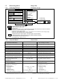
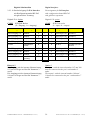
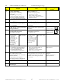
Weitere Unterlagen,
die im Zusammenhang mit
diesem Dokument stehen.
Further descriptions,
that relate to this document.
UL:7.2.1.1/2
Rack 6HE
R6 - Produkt-Beschreibung
Rack 6U
R6 - Product Description
UL:7.2.1.3
EMV-Rack 6HE
R6 EMV - Produkt-Beschreibung
EMC rack 6U
R6 EMC - Product Description
UL:7.2.2.1/2
Netz-Einschubmodul / 6HE
NE.. -3/-6 - Produkt-Beschreibung
SERVOdrive - SUCOnet K
CAN - Interface
Profibus DP
Interbus S
Power supply plug-in module / 6U
NE.. -3/-6 - Product Description
UL:7.5.2/3/4/5
SERVOdrive - SUCOnet K
CAN Interface
Profibus DP
Interbus S
UL:7.5.7.2
E/A - Interface
RP_EA - Produkt-Beschreibung
I/O - Interface
RP_EA – Product Description
UL: 7.9.4.2
Entstörhilfsmittel - Produkt-Beschreibung
Supression aids - Product Description
UL: 10.6.3
Serielles Übertragungsprotokoll
EASY-seriell - Produkt-Beschreibung
Serial transfer protocol
EASY-serial - Product Description
UL: 10.6.4
EASYRIDER - Produkt-Beschreibung
EASYRIDER - Product Description
UL: 10.6.5
BIAS - Befehlsbeschreibung
BIAS - Command Description
UL: 12
Zubehör
Produkt-Handbuch Serie 637 V10.08STEH00 (UL: 7.2.8.3)
Accessories
3
Product manual Series 637 V10.08STEH00 (UL: 7.2.8.3)
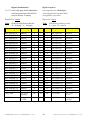
INHALTSVERZEICHNIS
CONTENTS
Seite/Page
Das Wichtigste zuerst ........................................ The most important thing first......................7
Sicherheitshinweise............................................ Safety precautions .........................................8
1
Allgemeines............................................ General Information ...................................10
1.1
1.1.1
1.1.2
1.1.3
1.2
1.2.1
1.3
1.3.1
1.3.2
1.3.3
1.3.4
1.3.5
1.3.6
1.4
1.4.1
Systembeschreibung ...........................................System description.................................................... 10
Digitale Kommunikation ....................................Digital communication ............................................. 11
Betriebskonfigurationen .....................................Operation configurations ......................................... 11
Kompatibilität zu Analogregler FRR AC S........ Compatibility to analog regulator FRR AC S .......... 12
Typenschlüssel ...................................................Key to the models...................................................... 14
Beispiel ...............................................................Example .................................................................... 14
Bemessungsdaten................................................Range data................................................................ 15
Isolierungskonzept..............................................Insulation concept .................................................... 15
Generelle Daten ..................................................General data............................................................. 15
Kompaktgeräte 637/K D6R ................................Compact units 637/K D6R........................................ 16
Einschubmodule 637/D6R..................................Plug-in modules 637/D6R ........................................ 17
Einphasen- und Dreiphasenversorgung ..............Single- and three-phase supply ................................ 18
Ausgangsleistung................................................Output power ............................................................ 19
Abmaße und Lageplan........................................Dimensions and layout ............................................. 20
Abmaße für Kompaktgerät .................................Dimensions for compact device
und Einschubmodul ............................................and plug-in module................................................... 20
EMV-Bügel (optional)........................................EMC bow (optional) ................................................. 21
für 8 TE - Regler.................................................for 8 HP drive........................................................... 21
für 16 TE - Regler...............................................for 16 HP drive......................................................... 21
Lageplan .............................................................Layout ....................................................................... 22
Lageplan Controller- Platine ..............................Layout of controller board ....................................... 22
Lageplan Power- Platine.....................................Layout of power board ............................................. 22
1.4.2
1.4.2.1
1.4.2.2
1.4.3
1.4.3.1
1.4.3.2
2
Anschlußbelegung................................. Connector assignment
und Funktionen..................................... and functions...............................................23
2.1
2.1.1
2.1.2
2.2
Übersicht der Anschlüsse ...................................General view of connections .................................... 23
vom Kompaktgerät K D6R 02...10.....................of the compact device K D6R 02 - 10 ....................... 23
vom Kompaktgerät K D6R 16...30.....................of the compact device K D6R 16 - 30 ....................... 24
Steckerbelegungen und.......................................Connector pin assignments
Kontaktfunktionen..............................................and contact functions................................................ 25
Leistungsanschlüsse ...........................................Power connections.................................................... 25
für Einschubmodul D6R.....................................for plug-in module D6R............................................ 25
Signalanschlüsse.................................................Signal connections.................................................... 26
Steuersignalstecker X10 .....................................Control signal plug X10 ........................................... 26
2.2.1
2.2.1.1
2.2.2
2.2.2.1
2.2.2.1.1 Komplette Darstellung X10........................................Complete representation X10 ............................................26
2.2.2.1.2 Anschlußbeispiel ........................................................Connection example...........................................................27
2.2.2.1.3 Ein- /Ausgänge ...........................................................Inputs / outputs ..................................................................28
2.2.2.2
Resolver ..............................................................Resolver .................................................................... 29
2.2.2.2.1 Funktionen der Resolverauswertung ..........................Functions of the resolver evaluation..................................29
2.2.2.2.2 Resolveranschlüsse X30.............................................Resolver connections X30 ..................................................29
2.2.2.3
Multifunktion X40.............................................. Multi-function X40 ................................................... 30
2.2.2.3.1
2.2.2.3.2
2.2.2.3.3
2.2.2.3.4
2.2.2.3.5
Beschreibung X40 ......................................................Description X40 .................................................................30
Inkremental-Ausgang .................................................Incremental output.............................................................31
Inkremental-Eingang ..................................................Incremental intput..............................................................32
Schrittmotor - Eingang Puls / Richtung......................Stepper motor input pulse / direction.................................33
Schrittmotor - Eingang Puls positiv / negativ.............Stepper motor input pulse positive / negative ....................33
2.2.3
2.2.3.1
Digitale Schnittstellen ........................................Digital interfaces...................................................... 34
Service-Schnittstelle COM1 (RS232) ................Service interface COM1 (RS232) ............................. 34
Produkt-Handbuch Serie 637 V10.08STEH00 (UL: 7.2.8.3)
4
Product manual Series 637 V10.08STEH00 (UL: 7.2.8.3)
INHALTSVERZEICHNIS
CONTENTS
Seite/Page
2.2.3.2
2.2.3.3
2.2.3.4
2.2.3.5
2.2.3.6
2.2.3.7
2.2.3.8
2.2.3.9
2.2.3.10
2.2.3.11
Feldbus-Schnittstelle COM2 .............................. Fieldbus interface COM2......................................... 35
zusätzliche E/A´s................................................ additional In-/Outputs .............................................. 35
Steckerbelegung für RS232................................ Pin assignment for RS232 ........................................ 36
Steckerbelegung für RS422/485......................... Pin assignment for RS422/485 ................................. 36
Steckerbelegung für CAN .................................. Pin assignment for CAN........................................... 37
Steckerbelegung für Profibus DP ....................... Pin assignment for Profibus DP............................... 37
Steckerbelegung für SUCOnet K ....................... Pin assignment for SUCOnet K................................ 37
Steckerbelegung für Interbus S .......................... Pin assignment for Interbus S .................................. 38
Steckerbelegung für E/A-Interface..................... Pin assignment for I/O interface .............................. 39
Steckerbelegung für E/A-Interface..................... Pin assignment for I/O interface .............................. 40
3
Betriebsarten..........................................Operating modes ......................................... 41
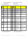
3.1
3.2
3.3
Betriebsarten und Kontaktfunktionen ................ Operating modes and pin functions ......................... 42
Konfigurierbare Kontaktfunktionen................... Configurable pin-functions ...................................... 43
Funktionsdiagramme von Ein- .......................... Function diagrams from inputs
und Ausgängen ................................................... and outputs ............................................................... 44
4
Mechanische Installation ......................Mechanical installation .............................. 45
4.1
4.2
4.3
Montage.............................................................. Mounting .................................................................. 45
Schaltschrank - Einbau....................................... Control cabinet - mounting ...................................... 45
Kühlung und Belüftung...................................... Cooling ..................................................................... 46
5
Elektrische Installation .........................Electrical installation.................................. 47
5.1
5.2
5.3
5.4
5.4.1
5.5
5.6
5.7
5.8
Sicherheit............................................................ Safety ........................................................................ 47
Gefahr elektrischer Schläge ............................... The danger of electric shocks................................... 47
Gefahrenbereiche ............................................... Danger areas............................................................ 47
Erdung, Sicherheitserdung ................................. Grounding, safety grounding ................................... 47
Erdungsanschlüsse ............................................. Ground connections ................................................. 48
Kurzschlußfestigkeit und Ableitströme.............. Short-circuit capability and discharge currents ...... 48
Sicherungen, Schütze, Filter............................... Fuses, contactors, filters .......................................... 49
Korrektur des Eingangstroms............................. Correction of supply current .................................... 51
Auslegung des Ballastwiderstandes ................... Selection of the brake resistor.................................. 52
6
Verdrahtungshinweise ..........................Wiring instructions ..................................... 54
6.1
6.2
6.3
6.4
6.5
6.6
6.7
6.7.1
6.7.2
6.7.3
Allgemeines........................................................ General Information................................................. 54
Steuersignalverdrahtung..................................... Control cabling ........................................................ 54
Leistungssignalverdrahtung................................ Power cabling .......................................................... 54
Rack - Montage .................................................. Installation of the rack ............................................. 54
Analoger Sollwert .............................................. Analog setpoint......................................................... 55
Sicherheitsregeln ................................................ Safety rules ............................................................... 55
Elektromagnetische Verträglichkeit (EMV) ...... Electromagnetic compatibility (EMC) ..................... 55
Montagehinweise ............................................... Hints for mounting ................................................... 56
Montagebeispiel ................................................. Example for mounting .............................................. 57
Eingehaltete Normen, Grenzwerte ..................... Achieveable specifications
und Rahmenbedingungen ................................... and conditions .......................................................... 58
7
Parametrierung und..............................Setting and
Programmierung ...................................programming............................................... 59
7.1
7.2
7.3
7.3.1
7.3.2
Jumper ................................................................ Jumper ...................................................................... 59
Digitale Kommunikation.................................... Digital communication............................................. 60
PROG-Taster-Funktionen................................... PROG-key functions................................................. 60
Beschreibung zu PROG-Taster .......................... Description for PROG-key ....................................... 60
Bedienung des PROG-Tasters............................ Operating via PROG-key ......................................... 61
Produkt-Handbuch Serie 637 V10.08STEH00 (UL: 7.2.8.3)
5
Product manual Series 637 V10.08STEH00 (UL: 7.2.8.3)
INHALTSVERZEICHNIS
CONTENTS
Seite/Page
8
Inbetriebnahme..................................... Commissioning............................................62
8.1
8.2
Voraussetzungen.................................................Preparations ............................................................. 62
Inbetriebnahme in Schritten ...............................Commissioning in steps ............................................ 63
9
Diagnose und Fehlersuche ................... Diagnosis and trouble shooting ..................66
9.1
9.2
9.3
7-Segment-Anzeige ............................................7-segment display ..................................................... 66
Reset eines Reglerfehlers ...................................Reset of a regulator trouble...................................... 68
Fehlersuche.........................................................Trouble shooting....................................................... 69
10
Blockschaltbild...................................... Block circuit diagram..................................70
11
Allgemeine technische Daten ............... General technical data ................................71
11.1
11.2
11.3
11.4
11.5
11.6
11.7
11.8
11.9
11.10
Leistungsteil .......................................................Power circuit ............................................................ 71
Steuerungsteil ..................................................... Control circuit .......................................................... 71
Signal Ein- und Ausgänge, Anschluß X10.........Signal inputs and outputs, connection X10 .............. 71
Digitale Regelung...............................................Digital control .......................................................... 72
Digitale Kommunikation ....................................Digital communication ............................................. 72
Resolverauswertung/Transmitterprinzip ............Resolver evaluation/transmitter principle................ 72
Controllersystem................................................. Controllersystem ...................................................... 73
Meßbuchsen MP1 und MP2 ...............................Measuring sockets MP1 and MP2............................ 73
Thermische Daten............................................... Thermal data ............................................................ 73
Mechanische Daten ............................................Mechanical data ....................................................... 73
12
Entsorgung ............................................ Disposal .......................................................73
13
Software................................................. Software .......................................................74
13.1
13.2
13.3
EASYRIDER < .................................................EASYRIDER <......................................................... 74
BIAS-Befehle .....................................................BIAS commands........................................................ 75
Erweiterte BIAS-Befehle ...................................Extended BIAS-commands........................................ 78
14
Index ...................................................... Index ............................................................79
15
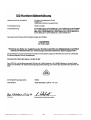
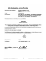
Zertifikate.............................................. Certificates...................................................82
16
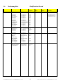
Änderungsliste ...................................... Modification Record ...................................90
Produkt-Handbuch Serie 637 V10.08STEH00 (UL: 7.2.8.3)
6
Product manual Series 637 V10.08STEH00 (UL: 7.2.8.3)
Das Wichtigste zuerst
The most important thing first
Wir bedanken uns für das Vertrauen,
das Sie unserem Produkt entgegenbringen.
Die vorliegende Betriebsanleitung dient der
Übersicht von technischen Daten und
Eigenschaften.
We thank you for the trust that you have
shown in our product.
The operating instructions presented here
serves as an overview of the technical data
and features.
Bitte lesen Sie vor Einsatz des Produktes
diese Bedienungsanleitung.
Please read the operating instructions before
putting the product to use.
Bei Rückfragen wenden Sie sich bitte an
Ihren nächsten Eurotherm-Ansprechpartner.
If you have any questions, please contact your
nearest Eurotherm representative
Der nicht sachgemäße Einsatz des Produktes
im Zusammenhang mit lebensgefährlicher
Spannung kann zu Verletzungen führen.
Des weiteren können dadurch
Beschädigungen an Motoren oder Produkten
auftreten. Berücksichtigen Sie deshalb bitte
unbedingt unsere Sicherheitshinweise.
Improper application of the product in
connection with dangerous voltage, can lead
to injuries.
In addition, damage can also occur to motors
or other products.
Therefore please observe strictly our safety
precautions.
Thema: Sicherheitshinweise
Topic: Safety precautions
Wir gehen davon aus, daß Sie als Fachmann
mit den einschlägigen Sicherheitsregeln,
insbesondere nach VDE 0100, VDE 0113,
VDE 0160, EN 50178 den Unfallverhütungsvorschriften der Berufsgenossenschaft und
den DIN-Vorschriften vertraut sind und mit
ihnen umgehen können.
Des weiteren sind die CE - Bestimmungen
einzuhalten und sicherzustellen.
We assume that as an expert, you are familiar
with the relevant safety regulations, especially
in accordance with VDE 0100, VDE 0113,
VDE 0160, EN 50178, the accident prevention
regulations of the employers liability insurance
company and the DIN regulations and that you
can use and apply them.
Also the CE - regulations are to be observed
and guaranteed.
Je nach Einsatzart sind weitere nationale
Normen, wie z. B. UL, DIN zu beachten.
Wenn der Einsatz unserer Produkte im
Zusammenhang mit Komponenten anderer
Hersteller erfolgt, sind auch deren
Betriebsanleitungen unbedingt zu beachten.
Depending on the kind of application, additional
norms e.g. UL, DIN are to be observed.
If our products are employed in connection with
components from other manufacturers, their
operating instructions are also to be strictly
observed.
Produkt-Handbuch Serie 637 V10.08STEH00 (UL: 7.2.8.3)
7
Product manual Series 637 V10.08STEH00 (UL: 7.2.8.3)
Sicherheitshinweise
!
Achtung !
Safety precautions
!
Attention !
Bei den digitalen Servoreglern handelt es sich im
Sinne der VDE 0160 um ein elektrisches
Betriebsmittel der Leistungselektronik (BLE) zur
Regelung des Energieflusses in Starkstromanlagen.
Sie sind ausschließlich zur Speisung von
Eurotherm- (oder von Eurotherm freigegebenen)
Servomotoren bestimmt.
Das Handling, die Montage, der Betrieb und die
Wartung sind nur unter der Bedingung und
Einhaltung der gültigen und/oder gesetzlichen
Vorschriften, Regelwerke und dieser technischen
Dokumentation zulässig.
The digital servo drives are in the sense of VDE
0160 power electronic equipments for regulating
the flow of energy in electrical power installations.
They are exclusively for supplying Eurotherm
(or Eurotherm approved) servomotors.
Handling, installation, operation, and maintenance
are only permitted under the conditions of and in
keeping with the effective and/or legal regulations,
regulation publications and this technical
document.
Die strikte Einhaltung dieser Regelwerke
ist vom Betreiber sicherzustellen.
The operator must make sure that these
regulations are strictly followed.
Konzept der galvanischen Trennung und
Isolation:
Concept of the galvanic separation and
insulation:
Galvanische Trennung und Isolation entsprechen
der VDE 0160 und der verstärkten Isolation.
Galvanically separation and insulation correspond
to VDE 0160 and the amplified insulation.
Zusätzlich sind alle digitalen Signal-Ein- und
Ausgänge entweder als Relais oder über OptoKoppler galvanisch getrennt. Dadurch wird eine
erhöhte Störsicherheit und Schadensbegrenzung
im Falle externer Fehlanschlüsse erreicht.
In addition all digital signal inputs and outputs are
galvanically separated either as a relay or via opto
coupler. In this way an increased interference
security and the limitation of damages in case of
external incorrect connections is given.
Die Spannungspegel dürfen die Sicherheitskleinspannung von 60V DC bzw. 25V AC gemäß
VDE 0160 nicht überschreiten.
The voltage level must not exceed the low safety
voltage 60V DC or 25V AC, respectively in
accordance with VDE 0160.
Die in weiteren Abschnitten (Punkten)
aufgeführten Sicherheitshinweise und Angaben
sind vom Betreiber einzuhalten.
The operator must make sure that these regulations
are strictly followed.
!
Gefahr !
Danger !
Hohe Berührungsspannung !
Schockgefahr !
Lebensgefahr !
High contact voltage !
Danger of getting shocked !
Danger to your life !
Vorsicht !
Ein Öffnen der Servoregler durch den
Betreiber ist aus Sicherheits- und Gewährleistungsgründen nicht zulässig. Die Voraussetzung für eine einwandfreie Funktion des
Servoreglers ist die fachgerechte Projektierung
!
Produkt-Handbuch Serie 637 V10.08STEH00 (UL: 7.2.8.3)
!
Caution !
Opening the servo drive by the operator is
prohibited due to reasons of safety and
guarantee. The requirement for problem-free
operation of the servo drive is the expert
configuring !
8
Product manual Series 637 V10.08STEH00 (UL: 7.2.8.3)
Sicherheitshinweise
Safety precautions
Bitte beachten !
Please observe !
Achten Sie vor allem darauf:
Especially to be complied with:
Zulässige Schutzklasse: Schutzerdung,
Betrieb nur mit vorschriftsmäßigem
Anschluß des Schutzleiters zulässig.
Der Betrieb des Servoreglers unter alleiniger
Verwendung einer FehlerstromSchutzeinrichtung als Schutz bei indirektem
Berühren ist nicht zulässig.
Der Servoregler darf nur im Rack oder im
Kompaktgehäuse eingesetzt werden. Des
weiteren ist der Regler ausschließlich für den
Schaltschrankbetrieb konzipiert.
Arbeiten am und mit dem Servoregler dürfen
nur mit isoliertem Werkzeug durchgeführt
werden.Installationsarbeiten dürfen nur im
spannungsfreien Zustand erfolgen. Bei
Arbeiten am Antrieb nicht nur den AktivEingang sperren, sondern den kompletten
Antrieb vom Netz trennen.
ACHTUNG - Stromschlaggefahr, nach dem
Ausschalten 3 Minuten Kondensatorentladezeit einhalten.
Lackversiegelte Schrauben erfüllen wichtige
Schutzfunktionen und dürfen weder betätigt
noch entfernt werden. Es ist nicht erlaubt, mit
Gegenständen jeglicher Art in das
Geräteinnere einzudringen.
Bei der Montage oder sonstigen Arbeiten im
Schaltschrank ist das Gerät gegen
herunterfallende Teile (Drahtreste, Litzen,
Metallteile usw.) zu schützen. Metallteile
können innerhalb des Servoreglers zu einem
Kurzschluß führen.
Vor der Inbetriebnahme sind zusätzliche
Abdeckungen zu entfernen, damit es zu
keiner Überhitzung des Gerätes kommen
kann. Bei Messungen am Servoregler ist
unbedingt auf Potentialtrennung zu achten!
The class of protecton which is permitted:
protective grounding; operation is only
permitted when the protective conductor is
connected according to regulations.
The operation of servo drives is not allowed
under the sole use of a residual current
operated protective device as protection
against indirect touching.
The servo drive may only be used in the rack
or in its compact enclousure. Furthermore
the regulator is designed solely for control
cabinet operation.
Work on or with the servo drive may only be
carried out with insulated tools.
Installation work may only be done in a
deenergized state. When working on the
drive, do not only block the Aktiv-input but
separate the complete drive from the mains.
CAUTION - risk of electrical shock, wait 3
minutes after switching off, for discharging
the capacitors.
Screws sealed with varnish fulfill an
important protection function and may not be
moved or removed.
It is prohibited to penetrate the inside of the
unit with objects of any kind.
Protect the unit from falling parts (pieces of
wire, fley, metal parts, etc.) during
installation or other work in the control
cabinet. Metal parts can lead to a short in
the servo drive.
Before putting into operation, remove
additional covers so that the unit does not
overheat. With measurements at the servo
drive it is absolutely necessary to observe the
potential separation!
STOP
Stop !
Für Schäden, die aufgrund einer
Nichtbeachtung der Anleitung oder
der jeweiligen Vorschriften entstehen,
übernimmt Eurotherm Antriebstechnik GmbH keine Haftung !!
Produkt-Handbuch Serie 637 V10.08STEH00 (UL: 7.2.8.3)
STOP
9
Stop !
Eurotherm Drives Limited is not
liable for damages whith occur
by not following the instructions
or the applicable regulations !!
Product manual Series 637 V10.08STEH00 (UL: 7.2.8.3)
1
Allgemeines
General Information
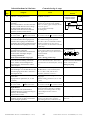
1.1
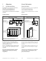
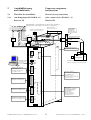
Systembeschreibung
System description
Der Digitale Servoregler dient der Strom-,
Drehzahl- und Lageregelung von
AC Servomotoren mit Resolver.
The digital servo drive serves to regulate the
current, speed and position of
AC servo motors with resolver.
Alle Regelkreise und Funktionen sind digital
realisiert.
All servo controls and functions are realized
digitally.
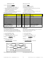
Systemvarianten
System variants
Rack-Version: 637/D6R....
Rack version: 637/D6R....
DC-Zwischenkreis
DC-BUS
optional R
Anschlußspannung:
Supply voltage:
1*oder 3*230VAC/50..60Hz
3*400...460VAC/50..60Hz
Kompakt-Version: 637/K D6R....
Compact version: 637/K D6R....
NEB...
AC
637/D6R
Ucc
Anschlußspannung:
Supply voltage:
637/D6R
DC
R
24V DC
AC
1*oder 3*230VAC/50..60Hz
3*400...460VAC/50..60Hz
637/K D6R
DC
Us 24V DC
Us 24VDC
M
M
M
Rack, R6
Netzeinschubmodul, NE
Power-supply
plug-in module
XN 1
6
5
4
3
2
1
NE...
o
o
o
o
o
o
o
o
o
o
o
o
o
o
o
o
o
o
o
o
o
o
o
o
Netzteil
Power supply unit
o
o
o
o
o
o
o
o
o
o
o
Regler
o
o
o
o
Lüfter / fan
o
Lüfter / Fan
Erläuterungen zu Rack und Netzteilmodulen sind in
gesonderter Beschreibung dokumentiert.
Explanations to rack and power supply modules are
documented in separate description.
Bei Bedarf kann die rückgeführte Bremsenergie in zusätzliche externe Ballastwiderstände abgeführt werden.
If required, the returned braking energy can
be drawn off into additional external ballast
resistors.
Die AC-Anschlußspannung wird direkt oder
über einen Trafo dem zugehörigen Netzteil
zugeführt.
The AC-supply voltage is fed directly or via
transformer to the associated power supply
module.
Die Geräte sind zum Betrieb an mittelpunktgeerdeten Netzen (TN-Netzen)
vorgesehen !
The devices are designed to be operated on
networks which are grounded on centre
point (TN networks) !
Produkt-Handbuch Serie 637 V10.08STEH00 (UL: 7.2.8.3)
10
Product manual Series 637 V10.08STEH00 (UL: 7.2.8.3)
1.1.1
Systembeschreibung
System description
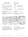
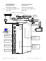
Digitale Kommunikation
Digital communication
Diagnose
Generell:
durch 7-Segment-Anzeige
Komfortabel: durch PC mit EASYRIDER <
(serielle Schnittstelle RS232)
Parametrierung
Low-Level: durch Prog.-Taster auf der
Frontseite
Komfortabel: durch PC mit EASYRIDER <
(serielle Schnittstelle RS232)
Diagnosis
General:
by 7-segment display
Comfortable: via PC by EASYRIDER <
(serial interface RS232)
Setup
Low Level: by Prog.-key on the front side
Kommunikation
Das serielle Übertragungsprotokoll ist offen
dokumentiert.
(Erläuterung siehe gesonderte Dokumentation)
Der Anwender hat Zugang zu allen Funktionen
und Parametern.
Communication
The serial-communication-protocol is free
documented.
(Explanation see seperate documentation)
Every user has unrestricted acces to all
functions and parameters.
7
EASYRIDER
=
Kundensoftware
: custom-made
software
o
SPS Software
PLC Software
SPS, binäre Satzwahl,+-10V
PLC, binary selection,+-10V
F
1.1.2
Bedienung
instructions
$
Comfortable: via PC by EASYRIDER <
(serial interface RS232)
F$ ?
F$ ?
F$ ?
F$
?
Diagnose
diagnostics
Betriebskonfigurationen
x
x
x
637/K D6R+
COM1
637/D6R
RS232,
Stromregler
COM2
current-loop
RS232,
Drehzahlregler
RS422,
speed-loop
RS485,
CAN-Bus,
SUCOnet K, Lageregler
Profibus DP, position-loop
Interbus S
......
SPS
PLC
X10
Parametrierung
setup
°
x Programmierung
programming
Operation configurations
Die Möglichkeiten reichen von einfacher
Strom- und Drehzahlregelung bis hin zu frei
programmierbaren, lagegeregelten Abläufen
(SPS) mit Hilfe der 1500 BIAS-Befehlsätze.
(siehe Kapitel 3 und 13.2)
The possibilities range from simple current and
speed control to programmable position control
processes (PLC) supported by the 1500 BIAScommand blocks.
(see chapter 3 and 13.2)
Produkt-Handbuch Serie 637 V10.08STEH00 (UL: 7.2.8.3)
11
Product manual Series 637 V10.08STEH00 (UL: 7.2.8.3)
1.1.3
Systembeschreibung
System description
Kompatibilität zu Eurotherm6 HE Analogregler FRR AC S
Compatibility to Eurotherm6 U analog regulator FRR AC S
(Nicht relevant bei Neuprojekten)
(Not required for new projects)
Die digitalen Servoregler sind weitgehend
pin- und funktionskompatibel zu den analogen
Geräten der Serie FRR AC S.
Die EASYRIDER < - Software gestattet die
Anpassung an Ihre bestehende Ausstattung.
(siehe Kapitel 3)
Weitere Anpassungen erfolgen über
Jumpereinstellungen (siehe Kapitel 7.1)
The digital servo drives are to a great extent
pin- and function compatible to the analog
devices of the FRR AC S series.
The EASYRIDER < software allows the
adaption to your existing equipment.
(see chapter 3)
Further adaptions can be done by solderjumpers (see chapter 7.1)
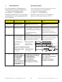
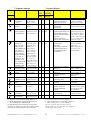
Kompatibilitätseinschränkungen:
Compatibility restrictions:
Einschränkung
Restriction
1 Externe Stromlimitierung
durch Analogeingang an X10.19
Im PC-Konfigurations-Menue kann die
Funktion Drehzahlreglerparameter (frei
normierbar) aktiviert werden. In wenigen
Fällen wurde der bei FRR AC S interne
Pull-Up-Widerstand mit einem externen
Pull-Down-Widerstand belastet, um eine
Stromreduzierung zu erreichen. Der PullUp-Widerstand im D6R+K D6R läßt sich
über die Lötbrücke JP101 aktivieren.
1 External current limiting
due to analog input at X10.19
In the PC configuration menu the function
speed regulator parameter (freely scaled)
can be activated. In few cases the internal
Pull-Up resistor with FRR AC S was
loaded with an external Pull-Down
resistor in order to reach a current
limiting. The Pull-Up resistor on the
D6R+K D6R can be activated via the
solder strip JP101.
2 InkrementalgeberausgangNullpunktverschiebung
Bei FRR AC S war eine Nullpunktverschiebung durch DIP-Schalter möglich.
Diese Funktion ist beim 637/D6R+K D6R
nicht realisiert.
2 Incremental encoder output-zero offset
With FRR AC S a zero drift was possible
by means of DIP switch. This function is
not realized with 637/D6R+K D6R.
3 Temp.-Überwachungs-Ausgang T2
(nur bei FRR AC S mit entsprechender
Optionsschaltung)
Das Signal T2 wird nicht mehr ausgegeben.
3 Temperature monitoring output T2
(only with FRR AC S with corresponding
option circuit)
T2 is no more signalized.
4 Bezugspotential
für alle digitalen Ein- und Ausgänge an
X10 ist jetzt X10.9.
4 Reference potential
all digital in- and output signals on X10
are referred to X10.9.
Produkt-Handbuch Serie 637 V10.08STEH00 (UL: 7.2.8.3)
12
Product manual Series 637 V10.08STEH00 (UL: 7.2.8.3)
Systembeschreibung
System description
Kompatibilität zu Eurotherm6 HE Analogregler FRR AC S
Compatibility to Eurotherm6 U analog regulator FRR AC S
(Nicht relevant bei Neuprojekten)
(Not required for new projects)
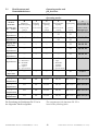
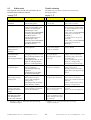
Einschränkung
Restriction
5 Temp.-Überwachung PTC
(nur bei FRR AC S mit entsprechender
Optionsschaltung)
Vor Abschaltung wird ca. 3 Sekunden das
Signal "WARNUNG" ausgegeben.
5 Temperature monitoring PTC
(only with FRR AC S with corresponding
option circuit)
Before switching off for approx 3 seconds
"WARNING" is signalized.
6
Reset
Der Anschluß X10.2 ist nicht mehr mit
der Resetfunktion belegt.
6
Reset
Connector X10.2 is no more assigned
with reset function.
7
n/I-Umschaltung
Anschluß X10.11 ist nicht mehr Bezugspotential für n/I-Umschaltung sondern
X10.9.
7
n/I-Switch over
Connector X10.11 is not reference
potential for n/I-switch over anymore, but
X10.9.
8
Warnung
Anschluß X10.7 ist nicht mehr
Bezugspotential für Warnungsausgang
sondern X10.9.
8
Warning
Connector X10.7 is not reference
potential for warning output anymore,
but X10.9.
9
Die maximale Betriebsspannung an
allen Signalausgängen von X10 beträgt
DC 45V.
9
The max. operating voltage on all signal
outputs of X10 is DC 45V DC.
10 Pin 26 an X50 ist intern nicht belegt und
muß frei bleiben !
10 Pin 26 on X50 is not assigned internally
and must be free !
Es kann nicht vollständig ausgeschlossen
werden, daß bei Sonderausführungen von
FRR AC S - Geräten zusätzliche Anpassungen
vorgenommen werden müssen.
One cannot completely rule out the possibility
that with special designs of FRR AC S devices
additional adjustments have to be made.
Produkt-Handbuch Serie 637 V10.08STEH00 (UL: 7.2.8.3)
13
Product manual Series 637 V10.08STEH00 (UL: 7.2.8.3)
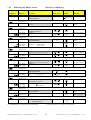
1.2
Typenschlüssel
Key to the models
Standard
Kennung
Marking
Typ:
Model:
XXX/
a
b
c
d
e
f
g
X
D6R
XX
.S3
-X
-X
-XXX
Beschreibung
XXX/ = 637 ≅ Eurotherm-Ausführung (blau), ohne
Angabe ≅ ASB-Ausführung (weiß/rot)
K
= 1-Achs-Kompakt
Digital-Servoregelsystem
= (entfällt bei Ausführung als Einschubgerät)
D6R = Digitaler 6HE Regler
Reglernennstrom:
02
= 2 Ampere
04
= 4 Ampere
06
= 6 Ampere
10
= 10 Ampere
16
= 16 Ampere
22
= 22 Ampere
30
= 30 Ampere
.S3
= Digitalregler 3. Generation
Zwischenkreisnennspannung:
-3
= 325V (230V AC)
-7
= 650V (460V AC)
-E
-232
-422
-485
-CAN
-SUC
-PDP
-IBS
–EA5
–EAE
–XXE
optional
= mit EMV-Bügeleinheit
im Regler:
zusätzliche Kommunikation über COM2
= RS 232 Schnittstelle
= RS 422 Schnittstelle
= RS 485 Schnittstelle
= CAN-Bus
= SUCOnet K
= Profibus DP
= Interbus S (Achtung: geänderte Frontplatte)
= E/A - Interface (5E, 2A)
COM2
= E/A - Interface (14E, 10A)
X200
= Kombination aus Komunikations-Interface
und E/A-Interface EAE (erste zwei Stellen
Kennung
Marking
a
b
c
d
e
f
g
Description
XXX/ = 637 ≅ Eurotherm-design (blue), without
information ≅ ASB-design (white/red)
K
= 1 axis compact
digital servo drive system
= (is not used with model plug-in device)
D6R = Digital 6U Regulator
Rated current:
02
= 2 amperes
04
= 4 amperes
06
= 6 amperes
10
= 10 amperes
16
= 16 amperes
22
= 22 amperes
30
= 30 amperes
.S3
= Digital drive 3 rd generation
Intermediate circuit rated voltage:
-3
= 325V (230V AC)
-7
= 650V (460V AC)
-E
-232
-422
-485
-CAN
-SUC
-PDP
-IBS
–EA5
–EAE
–XXE
vom Kom.-Interface + E für E/A-Interface EAE)
1.2.1
Beispiel
= with EMC bow unit
on the drive:
additional communication via COM2
= RS 232 interface
= RS 422 interface
= RS 485 interface
= CAN bus
= SUCOnet K
= Profibus DP
= Interbus S (Attention: changed front plate)
= I/O interface (5 I, 2 O)
COM2
= I/O interface (14 I, 10 O)
X200
= Combination of communication interface
and I/O interface EAE (the first two places
of com.-interface + E for I/O-interface EAE)
Example
Musterbeispiel für die Bestellangabe eines 1-AchsKompaktgerätes in Eurotherm-Ausführung:
Typ: 637/K D6R 02.S3-7-CAN
637/
= Eurotherm-Ausführung (blau)
K
= 1-Achs-Kompaktgerät
D6R
= Digitaler 6HE Regler
02
= 2 Ampere
.S3
= Digitalregler 3. Generation
-7
= 650V UCCN
-CAN = CAN-Bus
Typical example of an order of a 1-axiscompact device in Eurotherm-design:
Model: 637/K D6R 02.S3-7-CAN
637/
= Eurotherm-design (blue)
K
= 1 axis compact device
D6R
= Digital 6U Regulator
02
= 2 amperes
.S3
= Digital drive 3rd generation
-7
= 650V UCCN
-CAN = CAN-Bus
Produkt-Handbuch Serie 637 V10.08STEH00 (UL: 7.2.8.3)
14
Product manual Series 637 V10.08STEH00 (UL: 7.2.8.3)
1.3
Bemessungsdaten
Range data
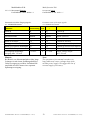
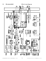
1.3.1
Isolierungskonzept
Insulation concept
COM1
Leistungsanschlüsse
Power-Terminals
L1, L2, L3
DC-Bus
M1, M2, M3
COM2
gem. RP-Modul
Remote IN dep. on RP-Mod.
X10
analog
Ballast
Break-cirquit
X10
digital
Kundenseitig
customer part
Netzteil
X30 1)
Us
X40
Power-Supply
DC 24 V
DC 24 V
AC
L1
N
PE
doppelte Isolierung gem. VDE 0160
double insulation ( VDE 0160)
Netzteilisolation
ACHTUNG ! Der Isolationsgrad der Steuerelektronik (COM1..X40) entspricht der Isolation des Netzteils
Erforderlich für sichere Trennung (PELV): doppelte Isolation
Insulation of control voltage supply
Take Care ! The insulation of control (Com1..X40) depends on the insulation of control voltage supply
Required for safe separation (PELV): double insulation
Zusatzisolation über Opto-Koppler oder Relais (keine Schutzisolation)
Additional insulation via opto-coupler or relay (without Safety-Functions)
1)
1.3.2
siehe zusätzliche Hinweise, Kapitel 2.2.2.2.2
see additional hints, capture 2.2.2.2.2
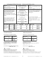
Generelle Daten
Schutzart
(für Schaltschrankeinbau)
Betriebstemperaturbereich
Lagertemperaturbereich
Luftdruck
Feuchtigkeit
Betriebstemperatur
reduzierter Betrieb
Reduzierung des Ausgangsstroms
Aufstellungshöhe h
reduzierter Betrieb
Reduzierung des Ausgangsstroms
Sicherheit
Überspannungskategorie des
Leistungsteils
Verschmutzungsgrad
für Schaltschrankeinbau
Schwingprüfung gemäß
DIN IEC 68-2-6, Prüfung FC
Prüfbedingungen:
Frequenzbereich
Amplitude
Beschleunigung
Prüfdauer je Achse
Frequenzdurchlaufgeschwindigkeit
General data
IP20
VDE 0160, Klasse 3K3
VDE 0160, class 3K3
-25°...+55° C
86 kPa - 106 kPa
5 % - 85% 40°C
0...40°C
>40°...< 50°C
1)
2% /°C
h ≤ 1000m
h > 1000...≤ 4000m
1)
1% / 100m
VDE 0160, UL, cUL
III, VDE 0160
VDE / UL: 2
10...57Hz 57...150Hz
0,075 mm
1g
10 Frequenzzyklen/sweep cycle
1 Oktave/min
Enclosure Rating
(for mounting in cubicle)
operating temperature range
storage temperature range
air pressure
Humidity
Opertating Temp
reduced operation
derating of the output current
Altitude h
reduced operation
Derating of the output current
Safety
Overvoltage-category of power
circuit
Pollution degree
for mounting in cubicle
Vibration test in accordance with
DIN IEC 68-2-6, test FC
Condition for testing
Frequency range
Amplitude
Acceleration
Test time per axis
Frequency sweep speed
1) Nur Geräte mit Lüfter verwenden. Für reduzierte
Betriebsbedingungen liegt keine UL-Abnahme vor.
1) Use only fan-cooled devices. For reduced operating
conditions, no UL-Approbation are available.
Produkt-Handbuch Serie 637 V10.08STEH00 (UL: 7.2.8.3)
15
Product manual Series 637 V10.08STEH00 (UL: 7.2.8.3)
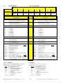
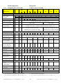
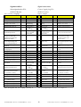
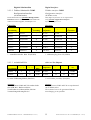
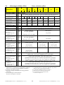
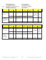
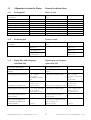
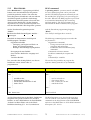
1.3.3
Bemessungsdaten
Range data
Kompaktgeräte 637/K D6R
Compact units 637/K D6R
Kompaktgeräte
Compact units
637 / K D6R 02 K D6R 04 K D6R 06 K D6R 10 K D6R 16 K D6R 22 K D6R 30
.S3
.S3
.S3
.S3
.S3
.S3
.S3
-3
-7
-3
-7
-3
-7
-3
-7
-7
-7
-7
Eingang Input
Netzspannung
supply voltage
50..60 Hz
Phasen Phases
Netz-Vorschaltung
Supply-preparation
Un
Einschaltstrombegrenzung
power-on current limit
Steuerspannung
control voltage
min.
[V]
max.
460
230
460
1;3
3
1;3
3
1;3
3
Sicherungen, Schütze, Filter etc siehe Kapitel 5.6
Fuses, contactors, filters see chapter 5.6
Typ
model
[V]
Is
DC
[A]
Ausgang Output
Sinus-Spann. Bei Un)
sine-wave volt. At Un)
Minderung von Unr
derating of Unr
Nennstrom eff.
rated current RMS
Unr
460
460
NTC 4 Ohm
1) Us
Steuerstrom incl. Lüfter
Control current incl. Fan
230
14
230 460
+ 10%
230
460
460
NTC 2 Ohm
24V DC +20% -10%, beachte: Isolationskonzept Kapitel 1.3.1
24V DC +20% -10%, attention: insulation-concept chapter 1.3.1
Dauer: max 1,5A Einschaltspitze: nom.
3A; max. 6A / 0,8 mS; 3A / 25 mS
Continuous: max 1,5A Power-On-Peak:
nom. 3A; max. 6A / 0,8 mS, 3A / 25 mS
Dauer: max 1,2A Einschaltspitze: nom. 3A;
max. 6A / 0,8 mS; 2,5A / 25 mS
Continuous: max. 1,2A Power-On-Peak:
nom. 3A; max.. 6A / 0,8 mS, 2,5A / 25 mS
[Veff] 220
447
220
447
220
447
220
447
447
447
447
3)
je nach Last und 1-Phasen oder 3-Phasen-Einspeisung. (siehe Kapitel 1.3.5)
depending on load and single or 3-phase supply. (see chapter 1.3.5)
2
4
6
10
16
22
30
3)
4
8
12
20
32
44
60
5 Sec
5 Sec
5 Sec
Inr
[A]
Maximalstrom eff
max. current RMS
Zeit für Imax/time for Imax
Imaxr
[A]
min. Mot.-Induktivität
(Klemme / Klemme)
min. motor inductance
(terminal / terminal)
Lph/ph [mH]
6,0
12,0
3,0
6,0
2,0
4,0
1,2
2,4
2,0
1,1
0,8
Ub
[V]
375
730
375
730
375
730
375
730
730
730
730
Pbmax
[kW]
4,5
8,7
4,5
8,7
6,7
13,0 11,2 21,7
29,0
34,8
34,8
Pbnenn
[W]
Rbint
Pd
Pmax
[Ω]
[W]
[kW]
100
30
1,4
300
30
1,7
100
30
1,4
300
30
1,7
100
30
1,4
300
30
1,7
100
30
1,4
300
30
1,7
[Ω]
47
82
47
82
27
47
15
27
20
15
15
[W]
29
29
29
29
29
29
29
29
36
36
36
9
2 Stück/Piece L 024 / 12TE * 25
1 Stück/Piece L 024 / 12TE * 15
12
9
12
9
12
9
min.
5 Sec
5 Sec
5 Sec
5 Sec
Ballast Brake circuit
Schaltschwelle DC
Setpoint DC
max. Leistung
max. power
Nennleistung
continuous power
interner Widerstand
internal resistor
min.ext. Widerstand
min. external resistor
2)
≤ 560
------
Allgemein General
Verlustleistung
power loss
Lüfter,Elektronik
fan, electronic
Lüfter-Typen
fan models
Endstufe pro A
power stage per A
Gewicht Weight
Weiteres further data
24V
DC
[W/A]
[kg]
12
2 Stück/Piece L 024 / 16TE x 25
1/2 Stück/Piece L 024 / 16TE x 20
12
12
12
5,0
8,8
siehe Kapitel 11
see chapter 11
1) empfohlen: Transformator-Netzteil
2) nur von Eurotherm freigegebene Typen verwenden
3) max. Dauerleistung reduziert auf 80%, siehe Kap. 1.3.6
1) suggested: transformer-based supply
2) use only Eurotherm-released types
3) max. continuous performance derated to 80%, see chapter 1.3.6
Produkt-Handbuch Serie 637 V10.08STEH00 (UL: 7.2.8.3)
16
Product manual Series 637 V10.08STEH00 (UL: 7.2.8.3)
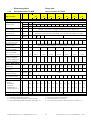
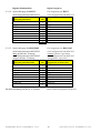
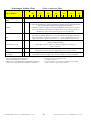
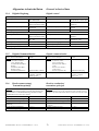
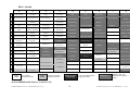
1.3.4
Bemessungsdaten
Range data
Einschubmodule 637/D6R
Plug-in modules 637/D6R
Einschubmodule
Plug-in modules
637 /
Eingang Input
DC-Versorgung Nenn
DC-BUS rated
Steuerspannung
control voltage
Steuerstrom
control current
Lüfter
Fan
Ausgang Output
Sinus-Spann. bei Un
sine-wave volt. at Un
Minderung von Unr
derating of Unr
Nennstrom eff
rated current RMS
Maximalstrom eff
max. current RMS
Ug
Us
1) Is
DC
2) Typ
model
Unr
Gewicht weight
Weiteres further data
D6R 04
.S3
-3
-7
D6R 06
.S3
-3
-7
650
325
650
325
650
[Veff] 220
447
220
447
220
447
[A]
[A]
Imaxr
[A]
min.
D6R 10
.S3
-3
-7
D6R 16
.S3
-3
-7
D6R 22
.S3
-3
-7
D6R 30
.S3
-3
-7
20
325 650 325 650 325 650 325 650
+ 10%
24V DC +20% -10%, beachte: Isolationskonzept Kapitel 1.3.1
24V DC +20% -10%, attention: insulation-concept chapter 1.3.1
Dauer: max 0,8A Einschaltspitze: nom. 2A; max 5A / 0,8 mS; 2A / 25mS
Continuous: max 0,8A Power-On-Peak: nom. 2A; max 5A / 0,8 mS, 2A / 25mS
--- L220 --L220K
L220G
K
325
Inr
Zeit f. Imax/time for Imax
min. Motor-Induktivität
(Klemme / Klemme)
min. motor inductance
(terminal / terminal)
Ballast Brake-Circuit
Schaltschwelle DC
setpoint DC
max. Leistung
max. power
Nennleistung
continuous rating
min. ext.Widerstand
2)
min. external resistor
Allgemein General
Verlustleistung
power loss
Elektronik
electronic
Endstufe pro A
output stage per A
min.
[V]
max.
[V]
D6R 02
.S3
-3
-7
220
447
220
447
220
447
220
447
3)
je nach Last und 1-Phasen oder 3-Phasen-Einspeisung (siehe Kapitel 1.3.5)
depending on load and single or 3-phase supply (see chapter 1.3.5)
2
4
6
10
16
22
30
3)
4
8
12
20
32
44
60
5 Sec
5 Sec
5 Sec
5 Sec
5 Sec
5 Sec
5 Sec
Lph/ph [mH]
6,0
12,0
3,0
6,0
2,0
4,0
1,2
2,4
1,0
2,0
0,55
1,1
0,4
0,8
Ub
[V]
375
730
375
730
375
730
375
730
375
730
375
730
375
730
Pbmax
[kW]
4,5
8,7
4,5
8,7
6,7
13,0 11,2 21,7 15,0 29,0 18,0 34,8 18,0 34,8
Pbnenn
[W]
≤ 560
[Ω]
33
63
33
63
22
43
12
24
10
20
8,2
15
8,2
15
[W]
20
20
20
20
20
20
20
20
20
20
20
20
20
20
[W/A
]
9
12
9
12
9
12
9
12
9
12
9
12
9
12
[kg]
1,5
siehe Kapitel 11
4,0
see chapter 11
1) empfohlen: Transformator-Netzteil
2) nur von Eurotherm freigegebene Typen verwenden
3) max. Dauerleistung reduziert auf 80%, siehe Kap. 1.3.6
1) suggested: transformer-based supply
2) use only Eurotherm-released types
3) max. continuous performance derated to 80%, see chapter 1.3.6
Produkt-Handbuch Serie 637 V10.08STEH00 (UL: 7.2.8.3)
17
Product manual Series 637 V10.08STEH00 (UL: 7.2.8.3)
Bemessungsdaten
Range data
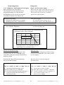
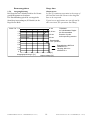
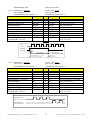
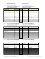
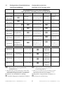
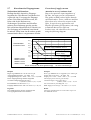
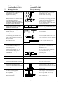
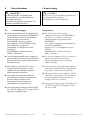
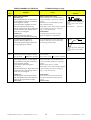
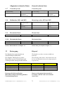
1.3.5 Einphasen- und Dreiphasenversorgung
Single- and three-phase supply
Durch Netzrippel im GleichstromZwischenkreis wird der Nutzbereich der
Ausgangsspannung wie folgt reduziert.
Die Reduktion wirkt sich auf die maximal
erreichbare Drehzahl eines Motors aus.
Due to the line-ripple of DC-Bus, the rate of
usable output voltage is derated like follows.
This deration effects the max. reachable
speed of the applied motor.
Dreiphaseneinspeisung:
Reduktion der unbelasteten Ausgangsspannung auf ca. 90% , maximal 85%
Three-phase-supply:
the unloaded output voltage will be
derated to approx. 90%, maximum 85 %
Einphaseneinspeisung:
siehe folgendes Diagramm:
Single-phase supply:
see following diagram:
Reduktion der Regler-Ausgangsspannung bei 1-Phasen-Betrieb
Derating of servo drive output voltage in case of single-phase supply
Ausgangsstrom [Aeff] Output current [Aeff]
12
10
8
1-ph 50Hz
637/K D6R02..06.S3-3
6
4
2
0
0
20
40
60
80
100 [%]
Ausgangsspannung in % der unbelasteten Spannung
Output voltage in % of unloaded condition
Hinweis für Parametrierung:
Um eine unerwartete Auslösung der Unterspannungsschwelle (EASYRIDER <) zu
vermeiden, sollte diese auf den Default-Wert
belassen werden.
Hints for setup:
To avoid unexpected tripping of undervoltage
threshold (EASYRIDER <),this value should
be set to default.
Erforderliche Motor-Klemmenspannung
für gewünschte Drehzahl.
Required motor-terminal-voltage for
specified speed.
Überschlagsrechnung (bis ca. 3000 RPM)
Approximation: (up to 3000RPM)
Ukl = 1,2 * (EMF * n / 1000) + I * (Rph + RL) [V]
Ukl = 1,2 * (EMK * n / 1000) + I * (Rph + RL) [V]
Ukl
EMK
Rph
RL
I
erforderliche Motorspannung [Veff]
Motor EMK [Vef] pro 1000 RPM
Motorinnenwiderstand (Klemme/Klemme) [Ω]
Leitungswiderstand der Motorleitung [Ω]
Motorstrom [Aeff]
Produkt-Handbuch Serie 637 V10.08STEH00 (UL: 7.2.8.3)
Ukl
EMF
Rph
RL
I
18
required motorvoltage [V RMS]
Back-EMF of motor [V RMS] / 1000 RPM
resistance of motor (between terminals) [Ω]
line resistance of motor cable [Ω]
motor-current [A RMS]
Product manual Series 637 V10.08STEH00 (UL: 7.2.8.3)
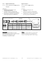
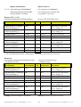
1.3.6
Bemessungsdaten
Range data
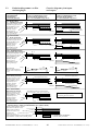
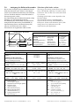
Ausgangsleistung
Output power
Bei Dauerlast im Vollastbereich ist die Grenze
gemäß Diagramm zu beachten.
Die Einschränkung spielt für servotypische
Start/Stop Anwendungen (S3-Betrieb) in der
Regel keine Rolle.
In case of continuous operation in the range of
full-load the limits like shown in the diagram
have to be respected.
Typical servo applications are not effected by
this restriction. (S3-operation: Start/Stop)
Imaxr / Inr 2,0
5 sec
1,8
6,25 sec
1,6
10 sec
1,4
Pulsdauer
auf unbelasteten Regler
bis Schutzreaktion
Duration of pulse
until supervising reaction
1,2
20 sec
1,0
Dauerbetrieb
Cont. operation
0,8
0,6
Einschränkung NUR bei
xD6R30.S3-x
Derating ONLY for
xD6R30.S3-x
0,4
0,2
0
0
20
40
60
Ausgangsspannung in [%]
Produkt-Handbuch Serie 637 V10.08STEH00 (UL: 7.2.8.3)
100 [%]
80
Output voltage [%]
19
Product manual Series 637 V10.08STEH00 (UL: 7.2.8.3)
1.4
Abmaße und Lageplan
Dimensions and layout
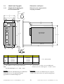
1.4.1
Abmaße für Kompaktgerät
und Einschubmodul
Dimensions for compact device
and plug-in module
Einzelheit
Detail
A
5
18
B
D1
C
D2
10
243
220
Einschubmodul
plug-in module
400
386
233
262
304
Lüfterplatz
space for fan
280
a
Einzelheit
Detail
5
9
5
A*
B
C
D1
D2
a
637/K D6R 02...10 Breite/Width 637/K D6R 16...30 Breite/Width
65,0 mm
14 TE/HP
104,6 mm
20 TE/HP
60,0 mm
100,0 mm
30,0 mm
71,0 mm
14,5 mm
14,5 mm
14,5 mm
14,5 mm
40,2 mm
8 TE/HP
80,4 mm
16 TE/HP
1 TE / HP ≈ 5,08mm
A* Bei Gehäuse in weiß, erfolgt zusätzliches
Maß
für Schraubenköpfe ca. 2 * 3mm = 6mm
A* with enclosure in white, occurred additional
measure of screw heads approx. 2 x 3mm = 6mm
Wichtig:
Bitte beachten Sie, daß frontseitig ein zusätzlicher
Platzbedarf von ca. 70 mm für die Signalgegenstecker zu berücksichtigen ist !
Important:
Make sure you leave an additional space of approx.
70 mm on the front side for the signal mating plugs !
Produkt-Handbuch Serie 637 V10.08STEH00 (UL: 7.2.8.3)
20
Product manual Series 637 V10.08STEH00 (UL: 7.2.8.3)
1.4.2
Abmaße und Lageplan
Dimensions and layout
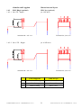
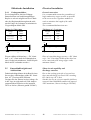
EMV-Bügel (optional)
EMC bow (optional)
1.4.2.1 für 8 TE - Regler
for 8 HP drive
Seitenansicht / side view
1.4.2.2 für 16 TE – Regler
Frontansicht / front view
for 16 HP drive
Seitenansicht / side view
Frontansicht / front view
EMV-Bügel für
EMC bow for
1
Resolver-Leitung
Resolver cable
2
Netz-Leitung
Mains cable
3
Motor-Leitung
Motor cable
Produkt-Handbuch Serie 637 V10.08STEH00 (UL: 7.2.8.3)
21
Product manual Series 637 V10.08STEH00 (UL: 7.2.8.3)
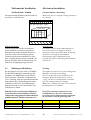
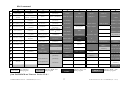
1.4.3
Abmaße und Lageplan
Dimensions and layout
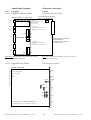
Lageplan
Layout
1.4.3.1 Lageplan Controller- Platine
Layout of controller board
Ansicht: Deckblech demontiert
View: cover disassembled
Bestückungsseite / Component side
Diagn.
Steckplatz
Konfigurationsinterface (Typ 1)
Slot for configuration
interface (model 1)
COM1
Sicherung
Fuse
X50
Steckplatz für
Konfigurationsinterface (Type 2)
Slot for
configuration interface (model 2)
COM2
X500
X10
X501
EVEN
mögliche Bestückungsvariante
siehe Kapitel 2.2.3
possible component variant
see chapter 2.2.3
ODD
Steckplatz für
Konfigurationsinterface (Type 3)
Slot for
configuration interface (model 3)
X30
X40
X520
X521
Anmerkung: Die Konfigurationsmodule sind nur nach
Abnahme der Stecker zugänglich.
Note: The configuration modules can only be reached
after removing the plugs.
1.4.3.2 Lageplan Power- Platine
Layout of power board
Lötseite / solder side
Diagn.
H15- Leistungsstecker
H15-power plug
COM1
X50
JP101
1
1
3
2
COM2
JP102
1
3
2
JP1
JP100
X10
2
3
1
3
2
JP3
1
1
3
2
JP2
2
3
1
JP4
X30
X40
Lötjumper JPxxx - Funktionen siehe Kapitel 7.1
solder jumper JPxxx - Function see chapter 7.1
Produkt-Handbuch Serie 637 V10.08STEH00 (UL: 7.2.8.3)
3 2
22
Product manual Series 637 V10.08STEH00 (UL: 7.2.8.3)
2
Anschlußbelegung
und Funktionen
Connector assignment
and functions
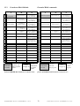
2.1
Übersicht der Anschlüsse
General view of connections
2.1.1
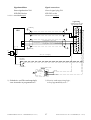
vom Kompaktgerät K D6R 02...10
of the compact device K D6R 02 - 10
Breite 14 TE
Width 14 HP
Leistungsanschluß 1 * (nicht K D6R10) oder 3 * 230V AC oder 3 * 400/460V AC
Power connection 1 x (not K D6R10) or 3 x 230V AC or 3 x 400/460V AC
PE
L3
L2
L1
N
M6 für Erdanschluß
M6 for ground connection
optional: externer Ballastwiderstand
optional: external break resistor
R
LNF K
PE
L
I
N
E
L3
230VAC
L2
L1
24VDC
PE
L3
L
O
A
D
L2
L1
N
LNF S
L
I
N
E
L
O
A
D
11
M2
12
M3
4
L1
5
L2
6
L3
Eurotherm-Motor-Leitung
Eurotherm-motor cable
XNP2
KMBR
oder / or
PE
L1
8
9
10
RB+ RB- M1
3
2
0V 24V
PE
L1
N
XNP1B
XNP1A
PE
X50
2
1
←
Anschlüsse siehe Kapitel 2.2.1
Connections see chapter 2.2.1
Eurotherm
AC-Servomotor
GND
Eurotherm-Leitung
Eurotherm-cable
Kn PC/D
Erdungsschiene
Schaltschrank
grounding bar
switching cabinet
Res.
3~
→ Prog.
Anschlußbelegung siehe Motor-Beschreibung
Connector assignment see motor description
COM1
RS232
o
Schirmung und Belegung
siehe Kapitel 2.2.3.2
shielding and assignment
see chapter 2.2.3.2
COM2
o
Remote IN : Rem. IN
(nur bei Interbus S-Anbindung)
siehe Kapitel 2.2.3.9
Remote IN : Rem. IN
(only with Interbus S connection)
see chapter 2.2.3.9
o
Anschlüsse siehe Kapitel 2.2.2
Connections see chapter 2.2.2
X10
Control
I/O
o
o
Anschlüsse siehe Kapitel 2.2.2.2
Connections see chapter 2.2.2.2
optional: X200
14 Eingänge / 10 Ausgänge
SUB D 26 (high density)
siehe Kapitel 2.2.3.11
optional: X200
14 inputs / 10 outputs
SUB D 26 (high density.)
see chapter 2.2.3.11
X30
IN
o
o
Anschlüsse siehe Kapitel 2.2.2.3
X40
Incr.
I/O
Connections see chapter 2.2.2.3
o
Produkt-Handbuch Serie 637 V10.08STEH00 (UL: 7.2.8.3)
23
Product manual Series 637 V10.08STEH00 (UL: 7.2.8.3)
2.1.2
Anschlußbelegung
und Funktionen
Connector assignment
and functions
Übersicht der Anschlüsse
General view of connections
vom Kompaktgerät K D6R 16...30
of the compact device K D6R 16 - 30
Breite 20 TE
Width 20 HP
Leistungsanschluß: 3 * 230V AC oder 3 * 400/460V AC
Power connection: 3 x 230V AC or 3 x 400/460V AC
PE
L3
L2
L1
N
optional: externer Ballastwiderstand
optional: external ballast resistor
M6 für Erdanschluß
M6 for ground connection
Erdungsschiene
Schaltschrank
grounding bar
switching cabinet
R
PE
L3
L2
230VAC
L1
LNF K
L
I
N
E
L
O
A
D
PE
L3
L2
4
L1
L1
5
L2
6
8
10
9
L3 RB+ RB- M1
Eurotherm-Motor-Leitung
Eurotherm-motor cable
11 12
M2 M3
X1B
24VDC
KMBR
3
2
0V 24V
X1A
PE
X50
2
1
Eurotherm
AC-Servomotor
GND
Eurotherm-Leitung
Eurotherm-cable
Kn PC/D
Anschlüsse siehe Kapitel 2.2.1
Connections see chapter 2.2.1
←
Res.
3~
→ Prog.
Anschlußbelegung siehe Motor-Beschreibung
Connector assignment see motor description
COM1
RS232
o
Schirmung und Belegung
siehe Kapitel 2.2.3.2
shielding and assignment
see chapter 2.2.3.2
COM2
Remote IN : Rem. IN
(nur bei Interbus S-Anbindung)
siehe Kapitel 2.2.3.9
Remote IN : Rem. IN
(only with Interbus S connection)
see chapter 2.2.3.9
o
o
Anschlüsse siehe Kapitel 2.2.2
Connections see chapter 2.2.2
X10
Control
I/O
o
o
Anschlüsse siehe Kapitel 2.2.2.2
Connections see chapter 2.2.2.2
optional: X200
14 Eingänge / 10 Ausgänge
SUB D 26 (high density.)
siehe Kapitel 2.2.3.11
optional: X200
14 inputs / 10 outputs
SUB D 26 (high density.)
see chapter 2.2.3.11
X30
IN
o
o
Anschlüsse siehe Kapitel 2.2.2.3
Connections see chapter 2.2.2.3
X40
Incr.
I/O
o
Produkt-Handbuch Serie 637 V10.08STEH00 (UL: 7.2.8.3)
24
Product manual Series 637 V10.08STEH00 (UL: 7.2.8.3)
2.2
Steckerbelegungen und
Kontaktfunktionen
Connector pin assignments
and contact functions
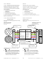
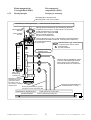
2.2.1
Leistungsanschlüsse
Power connections
2.2.1.1 für Einschubmodul D6R (rackrückseitig)
(H15-Steckerleiste nach DIN 41612)
for plug-in module D6R (at the rear of the rack)
(H15-multiple pin strip according to DIN 41612)
DC bus in the rack
DC-Bus im Rack
H 15-Leiste
H15 strip
1)
externer Ballastwiderstand
external Brake resistor
Leistungseinspeisung, DC-Bus
power feed-in, DC bus
parallel Pin 6 für Ströme >15Aeff
parallel pin 6 for currents >15Aeff
Motoranschluß
motor connection
parallel Pin 10
parallel pin 10
Motoranschluß
motor connection
parallel Pin 14
parallel pin 14
Motoranschluß
motor connection
parallel Pin 18
parallel pin 18
Bezugspotential für +Ucc
reference potential for +Ucc
parallel Pin 22
parallel pin 22
nicht benutzt
not used
Einspeisung-Steuespannung 24V DC
feed-in control voltage 24V DC
Bezugspotential zu +US Pin 28
reference potential to +US pin 28
Erde
ground
zu weiteren Reglern
to further regulators
>
Erdungsschiene
Schaltschrank
grounding bar
switching cabinet
R Ballast
4)
X50
4
-Rbext
6
+UCC
8
2)
M1
M2
M3
10
M1
12
Eurotherm-Motor-Leitung
Eurotherm-motor cable
KMB R
PE
2)
14
M2
16
2)
18
M3
0VP
20
2)
22
2)
24
3)
Eurotherm
AC-Servomotor
Res.
3~
PE
Netzseite
line side
26
+US
28
0VS
30
0VS
32
+24V DC - Steuerspannung
- control voltage
0V
PE
GND
Kleinspannungsseite
PELV - side
Rackrahmen oder Gehäuse
Rack frame or enclosure
Erdungsschraube im Rack
grounding screw in rack
PE
1) Faston-Flachsteckschuhe 6,3 mm
Faston-flat connector shoe 6,3 mm
2) Parallelverdrahtung für Nennströme >15A
parallel wires for nominal currents >15A
Erdungsschiene im
Schaltschrank Nähe Rack
grounding bar in switching
cabinet near rack
3) NUR bei Betrieb mit Trenntrafo erden !
PE
NICHT! erden bei Betrieb mit Spartrafo oder direkt am Netz !
ONLY ground when operating with isolated transformer !
DO NOT ground when operating with autotransformer or directly on mains !
4) Ballastwiderstand, sofern nicht von Netzteileinheit NE B...angesteuert
Brake-resistor, if not driven by power supply unit NE B...
Produkt-Handbuch Serie 637 V10.08STEH00 (UL: 7.2.8.3)
25
Product manual Series 637 V10.08STEH00 (UL: 7.2.8.3)
2.2.2
Signalanschlüsse
Signal connections
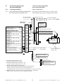
2.2.2.1 Steuersignalstecker X10
SUB D25 Buchse
Control signal plug X10
SUB D25 socket
2.2.2.1.1 Komplette Darstellung X10
Complete representation X10
extern / external
Kundenseite / customer side
intern / internal
X10
13
25
OUT
12
OUT
24
11
IN
23
Aktiv OK
Active OK
10
22
GND
Aktiv /Active
9
21
Versorgung für Ausg.
supply for output
8
20
7
19
6
18
5
17
4
16
IN
IN
Relais
JP102
0V SPS / 0V PLC
Bereit /ready
Warnung
warning
optional
optionally
0..+-10V normierbar
can be normed
0..+-10V normierbar
can be normed
0..+-10V normierbar
can be normed
Bezugspotential
reference potential
0..+-10V normierbar
can be normed
0V SPS externe Versorgung
Relais
24V SPS external Supply
1 3 2
JP100
I-Limit
Analog-
Monitor MP2 JP101 3
Nsoll
Nsetpoint
+12V
Analog-Monitor MP1
IN
0V SPS / 0V PLC
+12V 80mA
3
15
-12V 80mA
2
14
1
IN
Produkt-Handbuch Serie 637 V10.08STEH00 (UL: 7.2.8.3)
2
3
1
IN
IN
Schirm /shield
26
JP1
JP2
0V SPS /0V PLC
JP3
JP4
Product manual Series 637 V10.08STEH00 (UL: 7.2.8.3)
Signalanschlüsse
Signal connections
Steuersignalstecker X10
SUB D25 Buchse
Control signal plug X10
SUB D25 socket
2.2.2.1.2 Anschlußbeispiel
Connection example
reglerseitig
Signalstecker für X10
Typ: SUB D 25 S/R
großflächig
SPS
+/- 10V
14
1
15
2
16
3
17
4
18
19
1)
0V-Bezugspunkt, E/A-Versorgung / 0v reference point, I/O-supply
Eingang Aktiv / input active
1)
24V
+
L1
N
20
Ausgang Bereit / output ready
21
22
23
0V
-
24
großflächig
25
~
=
5
6
7
8
9
10
11
12
13
+24 V, E/A - Versorgung
+24V, I/O-supply
MaschinenEndschalter
+
Limit switch
Option: Bremse / brake
X10.23
Eurotherm
AC-Servomotor
3~
0 V SPS
1) Sicherheits- und Überwachungslogik,
vom Anwender zu programmieren !
1) Security- and supervising logic,
to be programmed by user !
Produkt-Handbuch Serie 637 V10.08STEH00 (UL: 7.2.8.3)
27
Product manual Series 637 V10.08STEH00 (UL: 7.2.8.3)
Signalanschlüsse
Signal connections
Steuersignalstecker X10
SUB D25 Buchse
Control signal plug X10
SUB D25 socket
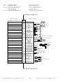
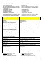
2.2.2.1.3 Ein- /Ausgänge
Funktion
Schirmanschluß
konfigurierbar (Kapitel 3)
Stabilisierte Hilfsspannung
-12VDC; max. 80 mA
konfigurierbar (Kapitel 3)
Bezugspunkt zu X10.18
Inputs / outputs
Typ
OPTO
OPTO
Strommonitor normierbar im
Drehzahlregler-Menü
durch JP100 (Lötjumper)
belegbar als freies und
schleifbares Potential des
BEREIT-Kontaktes
EIN: Regler störungsfrei
AUS: Reglerstörung oder
Versorgungsspannung aus
Bezugspunkt für digitale
Eingänge
Bezugspotential für
Analogsignale
konfigurierbar (Kapitel 3)
konfigurierbar (Kapitel 3)
konfigurierbar (Kapitel 3)
konfigurierbar (Kapitel 3)
konfigurierbar (Kapitel 3)
Stabilisierte Hilfsspannung
+12V DC; max 80 mA
Drehzahlistwert-Monitor,
normierbar
Relais
OPTO
OPTO
OPTO
OPTO
OPTO
Drehzahlsollwert; normierbar
differenziell gegen X10.5
Bestimmung der Stromgrenze
aktivierbar und normierbar
(0..+10V für 0.. Imax)
konfigurierbar (Kapitel 3)
Nominal: 24VDC
OPTO
H = Endstufe wird aktiv
L = Endstufe inaktiv
konfigurierbar (Kapitel 3)
konfigurierbar (Kapitel 3)
konfigurierbar (Kapitel 3)
OPTO
Relais
OPTO
OPTO
Ein- /Ausgang
PIN In- / output
Model Function
Schirm
Eingang
Ausgang
Hilfsspannung
Eingang
Eingang analog
0...+-10V
Ri = 10 kOhm
Ausgang analog,
Signal von Meßbuchse MP2
Optional
1
2
3
Ausgang
fest: bereit
8
output
fixed: ready
Bezugspunkt für
digitale Eingänge
Masse
9
Reference point for
digital inputs
ground
4
5
6
7
10
shield
input
output auxiliary
voltage
input
analog input
0...+-10V
Ri = 10 kOhm
analog output,
Signal from test
socket MP2
optional
OPTO
OPTO
Current monitor can be scaled
in the speed controller menu
Relay
11
12
13
14
15
16
Ausgang
Versorgung für
Ausgänge
Eingang
fest: aktiv
Ausgang
Eingang
Eingang
20
21
output
Supply for outputs
OPTO
configurable (chapter 3)
Nominal: 24V DC
22
input
fixed: active
output
input
input
OPTO
H = output stage is active
L = output stage inactive
configurable (chapter 3)
configurable (chapter 3)
configurable (chapter 3)
18
19
23
24
25
OPTO
OPTO
OPTO
OPTO
OPTO
via JP100 (solder jumper) can
be assigned as free and
loopable potential of the
READY contact
ON: regulator without fault
OUT: regulator fault or supply
voltage off
Reference point for digital
inputs
Reference potential for analog
signals
configurable (chapter 3)
configurable (chapter 3)
configurable (chapter 3)
configurable (chapter 3)
configurable (chapter 3)
stabilized auxiliary voltage
+12V DC; max 80 mA
actual speed value monitor,
scalable
Eingang
Ausgang
Ausgang
Eingang
Eingang
Ausgang
Hilfsspannung
Ausgang analog
Signal von Meßbuchse MP1
Eingang analog
0...+-10V
Ri = 10 kOhm
Eingang analog
0..+10V
Ri = 10 kOhm
17
input
output
output
input
input
output auxiliary
voltage
analog output signal
from test socket MP1
shield connector
configurable (chapter 3)
stabilized auxiliary voltage
-12VDC; max. 80 mA
configurable (chapter 3)
Reference point to X10.18
analog input
0...+-10V
Ri = 10 kOhm
analog input
0..+10V
Ri = 10 kOhm
nominal speed value; scalable
differential referenced to X10.5
Setting of the current limit can
be activated and scaled
(0..+10V for 0.. Imax)
Relay
OPTO
OPTO
Daten der digitalen Ein- und Ausgänge siehe Kap. 11
Data of the digital inputs and outputs see chapter 11
Produkt-Handbuch Serie 637 V10.08STEH00 (UL: 7.2.8.3)
28
Product manual Series 637 V10.08STEH00 (UL: 7.2.8.3)
2.2.2.2 Resolver
Resolver
2.2.2.2.1 Funktionen der Resolverauswertung
Functions of the resolver evaluation
Bildung eines digitalen Wertes für die Rotorlage
innerhalb einer Umdrehung, Auflösung: 12 oder
14 Bit; justierbar im Konfig.-Menue EASYRIDER.
Formation of a digital value for the rotor position
within one revolution, evaluation: 12 or 14 bit;
adjustable in the config. menu EASYRIDER.
daraus abgeleitet:
Ø Kommutierung entsprechend der
Polpaarzahl
Ø Drehzahlistwert
Ø Inkrementelle Positionsausgabe
Ø Positionswert für die Lageregelung
derivated from this:
Ø commutation according to
pole pair number
Ø actual speed value
Ø incremental position output
Ø position value for position regulation
Es dürfen ausschließlich von Eurotherm zugelassene
Resolver verwendet werden.
It is only allowed to use Eurotherm approved resolver
2.2.2.2.2 Resolveranschlüsse X30
SUB D 09 Buchse
Resolver connections X30
SUB D 09 socket
Resolveranschluß Kabelbelegung Eurotherm Leitung
Typ: KIR
Resolver connection cable pinning Eurotherm cable
Model: KIR
motorseitig / motorside
Resolver Gegenstecker
Typ :SIR
reglerseitig / controller side
X 30 Gegenstecker
SUB D 09 Stifte/ male
Ansicht von vorne
view: front
Ansicht von vorne
view: front
9
8
12
7
6
10
9
8
12
10
4
3
4
1
3
2
11
5
2
1
7
6
11
5
Pin
Nr.
Funktion
function
Farbe
colour
Pin
Nr.
1
2
3
4
8
7
5
6
9
10
11
12
sin +
sin –
cos +
cos –
weiß/white
braun/brown
grün/green
gelb/yellow
grau/gray
rosa/pink
rot/red
blau/blue
4
8
3
7
5
9
2
6
1
Träger carrier+
Träger carrierPTC optional 1)
PTC optional 1)
Schirm / shield
! Achtung ! Sicherheit und Isolation:
Der Temperatur-Sensor in der Motorwicklung
muß für sichere Trennung (PELV) isoliert
sein. Andernfalls wird die Isolationsklasse des
Reglers herabgesetzt, oder der Einsatz einer
zusätzlichen Trennstelle erforderlch.
Produkt-Handbuch Serie 637 V10.08STEH00 (UL: 7.2.8.3)
5
5
9
1
Ansicht : lötseite
view: solderside
Ansicht : lötseite
view: solderside
1)
9
6
Schirm großflächig auflegen
screen spread out
Abgebildeter Stecker nur bei Eurotherm - Motor
AC Mn und AC R !
1
6
Represented plug only with Eurotherm motor
AC Mn and AC R !
1)
29
! Attention ! Security and insulation:
The temperature sensor in the motor winding
must be insolated for secure division (PELV).
Otherwise, the insulation class of the drive
becomes reduced or the effort of an additional
galvanic seperation is required.
Product manual Series 637 V10.08STEH00 (UL: 7.2.8.3)
2.2.2.3 Multifunktion X40
Multi-function X40
2.2.2.3.1 Beschreibung X40
Description X40
Über einen programmierbaren E/A-Prozessor
kann X40 unterschiedlich konfiguriert werden.
(EASYRIDER <)
Standardmäßig vorhanden:
- Inkremental - Ausgang
- Inkremental - Eingang
- Schrittmotor - Puls-Eingänge
Via a programmable I/O processor, the X40
can be configured different. (EASYRIDER <)
Die freie Konfigurierbarkeit schafft z.B. ideale
Voraussetzungen für Synchronanwendungen.
The different configuration creates e.g. ideal
conditions for synchronous applications.
Standard functions:
- Incremental output
- Incremental input
- Stepper motor - pulse input
Allgemeine Daten
General data
Steckertyp:
Plug model:
Maximale Ein- oder Ausgangsfrequenz:
maximum input or output frequency:
Maximale Leitungslängen als Verbindung zu
galvanisch getrennten Anschlüssen
(Encoder oder Steuerungen)
maximum cable length connected to galvanical
insulated terminals (Encoder, controls)
Maximale Leitungslängen als Verbindung zu
Anschlüssen mit geerdeten Bezugspunkt
(andere Regler, Steuerungen)
maximum cable length connected to groundrelated terminals (other drives, controls)
Max. Anzahl von Signaleingängen an einem als
Inkrementalausgang konfigurierten Gerät
maximum number of signal inputs to one as
incremental-output configured device
Ausgangssignale:
output signals:
Differenzielle Logik-Pegel:
differential logic level:
nominaler Arbeitsbereich:
nominal range:
Eingangssignale:
input signals:
Differezieller Eing.-Pegel:
differential input level:
nominaler Arbeitsbereich:
nominal range:
nominale Signaldifferenz:
nominal signal difference:
Stromaufnahme:
current consumption:
X40
SUB D 09 Stecker
SUB D 09 male plug
200 kHz
200 kHz
25 m; größere Längen nach technischer Abklärung
25 m; for extended distances please contact our engineer
2 m, auf gute gemeinsame Erdung achten !
2 m, take care for good common grounding !
8
8
Treiber Typ MC34C87 oder kompatible, RS422
driver model MC34C87 or compatible, RS422
L ≤ 0,5V
H ≥ 2,5V
L ≤ 0,5V
H ≥ 2,5V
0,0 ... 5,0V
0,0 ... 5,0V
Empfänger Typ MC34C86 oder kompatible, RS422
receiver model MC34C86 or compatible, RS422
Diff min = 0,2V
diff min = 0,2V
0,0 ... 5,0V
0,0 ... 5,0V
1,0V
1,0V
1...4 mA (frequenzabhängig)
1...4 mA (depending on frequency)
Anmerkung: Master / Slave - Betrieb
1 Master maximal 8 Slaves
Bedingung: Geräte direkt nebeneinander !
Notice: Master / Slave operation
1 Master maximum 8 Slaves
Condition: Devices directly side by side !
Produkt-Handbuch Serie 637 V10.08STEH00 (UL: 7.2.8.3)
30
Product manual Series 637 V10.08STEH00 (UL: 7.2.8.3)
Multifunktion X40
Multi-function X40
2.2.2.3.2 Inkremental-Ausgang
Steckerbelegung X40
EASYRIDER < X40 Modus = 0
• Inkrementalgebersimulation zur Weiterverarbeitung in Positioniermodulen
• Standard: 1024 Inkremente
weitere anwählbare Pulszahlen: 512, 256, 128
Incremental output
Connector pin assignment X40
EASYRIDER < X40 mode = 0
• Incremental encoder simulation for processing
in positioning modules
• Standard: 1024 increments
further selectable pulse numbers: 512, 256, 128
Parameterbereich der Eingangssignale:
10...1000000 Inkremente
Parameter area of the input signals:
10...1000000 increments
Funktion
Bezeichnung
Kanal B
Kanal B invertiert
Schirmanschluß
Kanal A
Kanal A invertiert
Bezugspotential zu Pin 9
Kanal Z invertierter Nullimpuls
Kanal Z; Nullimpuls
Versorgungs-SpannungsAusgang max. 150 mA
B
/B
Schirm
A
/A
0 VS
/Z
Z
+ 5 VDC
Pin Designation Function
1
2
3
4
5
6
7
8
9
B
/B
Shield
A
/A
0 VS
/Z
Z
+ 5 VDC
Channel B
Channel B inverted
Shield connector
Channel A
Channel A inverted
Reference potential to pin 9
Channel Z inverted zero impulse
Channel Z, zero impulse
Supply voltage output
max. 150 mA
Dimensionierungshinweis:
Der Eingangsfrequenzbereich der angeschlossenen Steuerung muß mindestens den
Wert der Pulsausgangsfrequenz an X40 haben.
Design rule:
The capability of input-frequency of any connected
device must meet at least the value
of pulse outputs on X40.
n = max. Drehzahl (1/min)
x = Inkremente z. Bsp. 1024
f = Ausgangsfrequenz an X40.1,2,4,5
Formel: f = 1,2 * (n * x) = [Hz]
60
n = max. speed (rpm)
x = increments e.g. 1024
f = output frequency at X40.1,2,4,5
Formula: f = 1,2 * (n * x) = [Hz]
60
Beispiel: n = 4000 1/min
1,2 * (4000 * 1024)
= 81920 Hz
f=
60
Example: n = 4000 rpm
1,2 * (4000 * 1024)
= 81920 Hz
f=
60
A
/A
B
/B
Z
/Z
Inkrementale Ein- oder Ausgänge
Incremental inputs or outputs
Produkt-Handbuch Serie 637 V10.08STEH00 (UL: 7.2.8.3)
31
Product manual Series 637 V10.08STEH00 (UL: 7.2.8.3)
Multifunktion X40
Multi-function X40
2.2.2.3.3 Inkremental-Eingang
EASYRIDER < X40 Modus = 1
Incremental intput
EASYRIDER < X40 mode = 1
Parameterbereich der Eingangssignale:
10...1000000 Inkremente
Parameter area of the input signals:
10...1000000 increments
Funktion
Bezeichnung
Kanal B
Kanal B invertiert
Schirmanschluß
Kanal A
Kanal A invertiert
Bezugspotential zu Pin 9
Kanal Z invertierter Nullimpuls
Kanal Z; Nullimpuls
Versorgungs-SpannungsAusgang max. 150 mA
B
/B
Schirm
A
/A
0 VS
/Z
Z
+5 VDC
Pin Designation Function
1
2
3
4
5
6
7
8
9
B
/B
Shield
A
/A
0 VS
/Z
Z
+5 VDC
Channel B
Channel B inverted
Shield connector
Channel A
Channel A inverted
Reference potential for pin 9
Channel Z inverted zero impulse
Channel Z, zero impulse
Supply voltage output
max. 150 mA
Hinweis:
Bei Betrieb von Inkrementalgebern über lange
Leitungen ist mit einem Spannungsabfall der
Geberversorgung zu rechnen. Im Bedarfsfall
empfiehlt sich der Einsatz einer separaten
Spannungsversorgung.
Note:
The operation of incremental encoders via
long cables may cause a voltage drop of the
encoder power supply. We suggest the use of
external supply if necessary.
Produkt-Handbuch Serie 637 V10.08STEH00 (UL: 7.2.8.3)
32
Product manual Series 637 V10.08STEH00 (UL: 7.2.8.3)
Multifunktion X40
Multi-function X40
2.2.2.3.4 Schrittmotor - Eingang
Puls / Richtung
EASYRIDER < X40 Modus = 2
Stepper motor input
pulse / direction
EASYRIDER < X40 mode = 2
Funktion
Bezeichnung
Ausgang: Regler aktiv invertiert
Ausgang: Regler aktiv
Schirmanschluß
Puls invertiert
Puls
Bezugspotential
Richtung invertiert
Richtung
Versorgungs-SpannungsAusgang max. 150 mA
/READY
READY
Schirm
/P
P
GND
/R
R
+5 VDC
Pin Designation
1
2
3
4
5
6
7
8
9
/READY
READY
Shield
/P
P
GND
/R
R
+5 VDC
Function
output: drive active inverted
output: drive active
Shield connector
Pulse inverted
Pulse
Reference potential
Direction inverted
Direction
Supply voltage output
max. 150 mA
Puls
pulse
Richtung
direction
1
2
Drehrichtung (-)
turn direction (-)
1 Vorbereitungszeit
set-up time
2,5 µs
2,5 µs
2.2.2.3.5 Schrittmotor - Eingang
Puls positiv / negativ
EASYRIDER < X40 Modus = 3
Funktion
Bezeichnung
Ausgang: Regler aktiv invertiert
Ausgang: Regler aktiv
Schirmanschluß
Puls Richtung (-) invertiert
Puls Richtung (-)
Bezugspotential
Puls Richtung (+) invertiert
Puls Richtung (+)
Versorgungs - Spannungs Ausgang max. 150 mA
/READY
READY
Schirm
/PPGND
/P+
P+
+5 VDC
2
Drehrichtung (+)
turn direction (+)
Haltezeit = 0
hold time = 0
Stepper motor input
pulse positive / negative
EASYRIDER < X40 mode = 3
Pin Designation
1
2
3
4
5
6
7
8
9
/READY
READY
Shield
/PPGND
/P+
P+
+5 VDC
Function
output: drive active inverted
output: drive active
Shield connector
Pulse direction (-) inverted
Pulse direction (-)
Reference potential
Pulse direction (+) inverted
Pulse direction (+)
Supply voltage output
max. 150 mA
Puls Richtung (+)
pulse direction (+)
Puls Richtung (-)
pulse direction (-)
Produkt-Handbuch Serie 637 V10.08STEH00 (UL: 7.2.8.3)
33
Product manual Series 637 V10.08STEH00 (UL: 7.2.8.3)
2.2.3
Digitale Schnittstellen
Digital interfaces
2.2.3.1 Service-Schnittstelle COM1 (RS232)
Standard
Service interface COM1 (RS232)
standard
Funktionen:
Ø Unterstützung aller Diagnose- und
Parametrierungsaufgaben
Ø Anschluß an Ihren PC erfolgt mit dem
Eurotherm - Kommunikationskabel KnPC/D
Ø Kommunikation erfolgt über das EurothermBedienungsprogramm (EASYRIDER <)
Functions:
Ø Supporting all diagnosis and
setup tasks
Ø Connection to your PC is made with the
Eurotherm communication cable KnPC/D
Ø Communication is made via the Eurotherm
operating program (EASYRIDER <)
Kommunikationskabel Typ: KnPC/D
Communication cable model: KnPC/D
SnXA0
2
Funktion
1
3
Ansicht: Lötseite
view: solder side
Kabelschirm
Cable shield
Bezeichnung
Pin
Designation
Function
SUB D 09
SnXA0 SUB D 09
Bezugspotential GND
1
5
GND
Reference potential
Sendedaten
TXD
2
3
TXD
Transmitted data
Empfangsdaten RXD
3
2
RXD
Received data
-
Metal enclosure Shield
Schirm
Metallgehäuse
-
Ansicht: Lötseite
view: solder side
Anmerkung:
Die Service-Schnittstelle RS232 ist nicht
galvanisch getrennt und sollte aus diesem Grunde
nicht als Betriebsschnittstelle (“feste
Verdrahtung“) vorgesehen werden !
Notice:
The service interface RS232 is not galvanically
separated and should not be planned for this
reason as a operating interface ("firm wiring")!
Produkt-Handbuch Serie 637 V10.08STEH00 (UL: 7.2.8.3)
34
Product manual Series 637 V10.08STEH00 (UL: 7.2.8.3)
Digitale Schnittstellen
Digital interfaces
2.2.3.2 Feldbus-Schnittstelle COM2
Konfigurations-Interface
Fieldbus interface COM2
Configuration interface
(SUB D09 Buchse)
(SUB D09 socket)
Durch den Einsatz von optionalen KonfigurationsInterfaces können viele unterschiedliche Funktionen
realisiert werden. Lageplan, siehe Kapitel 1.4.3
Many different functions can be implemented
using optional configuration interfaces.
Layout, see chapter 1.4.3
Übersicht:
Overview:
Interface
designation
Interface
-
RP 232
RS 232
-
RS 422/485
-
RP 422
RS 422/485
-
RP 485
RS 422/485
X
RP 485
RS 422/485
X
RP CAN
CAN
X
RP CAN
CAN
X
RP PDP
Profibus DP
X
RP PDP
Profibus DP
X
RP SUC
SUCOnet K
X
RP SUC
SUCOnet K
X
* RP IBS
Interbus S
X
* RP IBS
Interbus S
X
InterfaceBezeichnung
Schnittstelle
RP 232
RS 232
RP 422
galvanische
Trennung
galvanic
seperation
* zusätzlicher Stecker Rem. IN (SUB D)
* additional plug Rem. IN (SUB D)
2.2.3.3 zusätzliche E/A´s
additional In-/Outputs
InterfaceEingänge Ausgänge Anschluß Interface
designation
Bezeichnung
über
RP EA5
RP EAE
1)
Inputs
Outputs
Connection
via
5
2
COM2
RP EA5
5
2
COM2
14
10
X200
RP EAE
14
10
X200
1) keine Feldbusmöglichkeit (Interface)
1) no Fieldbus possibility (Interface)
Achtung:
Die Anschlüsse COM2 und X30 werden beide
über SUB D09 - Buchse realisiert.
Vom Kunden ist sicherzustellen, daß eine
Vertauschung nicht möglich ist !
Caution:
The connections COM2 and X30 are implemented
via SUB D09 socket.
The costumer have to be guaranteed that an
interchanging is not possible!
Produkt-Handbuch Serie 637 V10.08STEH00 (UL: 7.2.8.3)
35
Product manual Series 637 V10.08STEH00 (UL: 7.2.8.3)
Digitale Schnittstellen
Digital interfaces
2.2.3.4 Steckerbelegung für RS232
mit Konfigurationsmodul RP 232
Belegung als RS232
RXD
TXD
GND
-
Pin assignment for RS232
with configuration board RP 232
Pin
1
2
3
4
5
6
7
8
9
2.2.3.5 Steckerbelegung für RS422/485
mit Konfigurationsmodul RP 422
ohne galvanische Trennung
mit Konfigurationsmodul RP 485
mit galvanischer Trennung
Belegung als RS422/485
Data In
GND
Data In invertiert
Data Out invertiert
Data Out
-
assignment as RS232
RXD
TXD
GND
-
Pin assignment for RS422/485
with configuration board RP 422
without galvanic seperation
with configuration board RP 485
with galvanic seperation
Pin
1
2
3
4
5
6
7
8
9
assignment as RS422/485
Data In
GND
Data In inverted
Data Out inverted
Data Out
-
Parallelverdrahtung von bis zu 16 Geräten
Daisy-chain wiring up to 16 devices
Produkt-Handbuch Serie 637 V10.08STEH00 (UL: 7.2.8.3)
36
Product manual Series 637 V10.08STEH00 (UL: 7.2.8.3)
Digitale Schnittstellen
Digital interfaces
2.2.3.6 Steckerbelegung für CAN
mit Konfigurationsmodul RP CAN
mit galvanischer Trennung
Beschreibung
Bezeichnung
CAN_L Leitung
CAN_L
Pin assignment for CAN
with configuration board RP CAN
with galvanic seperation
Pin
1
2
Designation
Description
CAN_L
CAN_L bus line
(dominant low)
Masse
Masse
CAN_H Leitung
(dominant low)
GND
GND
CAN_H
3
4
5
6
7
GND
GND
CAN_H
(dominant high)
-
Ground
Ground
CAN_H bus line
(dominant high)
-
8
9
2.2.3.7 Steckerbelegung für Profibus DP
mit Konfigurationsmodul RP PDP
mit galvanischer Trennung
Beschreibung
Bezeichnung
B-Leitung
Sendebereitschaft
Masse
Potential +5V
A-Leitung
-
B
RTS
GND
+5V
A
-
Bezeichnung
Datenleitung +
Signalmasse
Datenleitung -
TA/RA
SGND
TB/RB
-
Produkt-Handbuch Serie 637 V10.08STEH00 (UL: 7.2.8.3)
-
Pin assignment for Profibus DP
with configuration board RP PDP
with galvanic seperation
Pin
1
2
3
4
5
6
7
8
9
2.2.3.8 Steckerbelegung für SUCOnet K
mit Konfigurationsmodul RP SUC
mit galvanischer Trennung
Beschreibung
-
Designation
Description
B
RTS
GND
+5V
A
-
Line B
Request to send
Ground
Potential +5V
Line A
-
Pin assignment for SUCOnet K
with configuration board RP SUC
with galvanic seperation
Pin
1
2
3
4
5
6
7
8
9
Designation
Description
TA/RA
SGND
TB/RB
-
Data line +
Signal ground
Data line -
37
Product manual Series 637 V10.08STEH00 (UL: 7.2.8.3)
Digitale Schnittstellen
Digital interfaces
2.2.3.9 Steckerbelegung für Interbus S
mit Konfigurationsmodul RP IBS
mit galvanischer Trennung
Pin assignment for Interbus S
with configuration board RP IBS
with galvanic seperation
Remote OUT (COM2)
abgehende Schnittstelle (SUB D09 Buchse)
Remote OUT (SUB D09 socket)
Designation
Description
1
DO2
DI2
2
DI2
GND I
+5V
/DO2
3
4
5
6
GND I
+5V
/DO2
/DI2
7
/DI2
RBST
8
9
RBST
Data line OUT forward
(error voltage A)
Data line IN backward
(error voltage A)
Reference potential
VCCI
Data line OUT forward
(error voltage B)
Data line IN backward
(error voltage B)
Reporting input
Beschreibung
Bezeichnung
Datenleitung OUT Hinweg
(Differenzspanung A)
Datenleitung IN Rückweg
(Differenzspanung A)
Bezugspotential
VCCI
Datenleitung OUT Hinweg
(Differenzspanng B)
Datenleitung IN Rückweg
(Differenzspanung B)
Meldeeingang *
DO2
Pin
* für weiterführende Interbus-S-Schnittstelle
* to forward Interbus-S interface
Remote IN
ankommende Schnittstelle (SUB D09 Stecker)
≅ zusätzlicher Stecker
Remote IN (SUB D09 plug)
≅ additional plug
Designation
Description
1
DO1
DI1
2
DI1
GND I
/DO1
3
4
5
6
GND I
/DO1
/DI1
7
/DI1
-
8
9
-
Data line IN forward
(error voltage A)
Data line OUT backward
(error voltage A)
Reference potential
Data line IN forward
(error voltage B)
Data line OUT backward
(error voltage B)
-
Beschreibung
Bezeichnung
Datenleitung IN Hinweg
(Differenzspanung A)
Datenleitung OUT Rückweg
(Differenzspanng A)
Bezugspotential
Datenleitung IN Hinweg
(Differenzspanung B)
Datenleitung OUT Rückweg
(Differenzspanung B)
-
DO1
Pin
Achtung: spezielle Frontplatte erforderlich !
Attention: specific front panel is required !
Produkt-Handbuch Serie 637 V10.08STEH00 (UL: 7.2.8.3)
38
Product manual Series 637 V10.08STEH00 (UL: 7.2.8.3)
Digitale Schnittstellen
Digital interfaces
2.2.3.10 Steckerbelegung für E/A-Interface
mit Konfigurationsmodul RP EA5
mit galvanischer Trennung
Pin assignment for I/O interface
with configuration board RP EA5
with galvanic seperation
Digitale E/A Option
Digitale I/O option
COM2
COM2
SUB D09 Buchse
(E = Eingang ; A = Ausgang )
Bezeichnung
Bemerkung
SUB D 09 socket
(I = input; O = output)
Status
PIN
Status
BIAS Eingang 101 standard
E
1
BIAS Eingang 102 standard
E
BIAS Eingang 107 standard
Designation
Comment
I
BIAS input 101
standard
2
I
BIAS input 102
standard
E
3
I
BIAS input 107
standard
BIAS Eingang 108 standard
E
4
I
BIAS input 108
standard
0VSPS
B
5
B
0VSPS
ground reference
0VSPS
BIAS Eingang 106 standard
E
6
I
BIAS input 106
standard
BIAS Ausgang 109 standard
A
7
O
BIAS output 109 standard
BIAS Ausgang 110 standard
A
8
O
BIAS output 110 standard
UB
9
UB
+24VSPS
Bezugsmasse
0VSPS
ext. +24V
Speisung
+24VSPS
ext. +24V feed-in
Hinweis !!
Die Eingänge mit der internen Nummerierung
107 und 108 liegen auf den Pin Nummern 3
und 4.
Die Ausgänge mit der internen Nummerierung
109 und 110 liegen auf den Pin Nummern 7
und 8.
Notice !!
The input´s with the internal number 107 and 108
must be connected to the pin´s with number 3
and 4.
The output´s with the internal number 109 and
110 must be connected to the pin´s with number 7
and 8.
Produkt-Handbuch Serie 637 V10.08STEH00 (UL: 7.2.8.3)
39
Product manual Series 637 V10.08STEH00 (UL: 7.2.8.3)
Digitale Schnittstellen
Digital interfaces
2.2.3.11 Steckerbelegung für E/A-Interface
mit Konfigurationsmodul RP EAE
mit galvanischer Trennung
Pin assignment for I/O interface
with configuration board RP EAE
with galvanic seperation
Digitale E/A Option
Digital I/O option
X200
X200
SUB D26 High Density Buchse
(E = Eingang ; A = Ausgang)
SUB D26 high density socket
(I = input; O = output)
Bezeichnung
Bemerkung
Status
PIN
Status
Bias Eingang 201
Bias Eingang 202
Bias Eingang 203
Bias Eingang 204
Bias Eingang 205
Bias Eingang 206
Bias Eingang 207
Bias Eingang 208
Bias Ausgang 209
Bias Ausgang 210
Bias Eingang 211
Bias Eingang 212
Bias Eingang 213
Bias Eingang 214
Bias Eingang 215
Bias Eingang 216
Bias Ausgang 217
Bias Ausgang 218
Bias Ausgang 219
Bias Ausgang 220
Bias Ausgang 221
Bias Ausgang 222
Bias Ausgang 223
Bias Ausgang 224
+24 V SPS
Standard
Standard
Standard
Standard
Standard
Standard
Standard
Standard
Standard
Standard
Standard
Standard
Standard
Standard
Standard
Standard
Standard
Standard
Standard
Standard
Standard
Standard
Standard
Standard
Ext. +24 V
Speisung
Bezugsmasse
0 V SPS
E
E
E
E
E
E
E
E
A
A
E
E
E
E
E
E
A
A
A
A
A
A
A
A
Ub
1
2
3
4
5
6
7
8
9
10
11
12
13
14
15
16
17
18
19
20
21
22
23
24
25
I
I
I
I
I
I
I
I
O
O
I
I
I
I
I
I
O
O
O
O
O
O
O
O
Ub
B
26
B
0 V SPS
Produkt-Handbuch Serie 637 V10.08STEH00 (UL: 7.2.8.3)
40
Designation
Comment
Bias input 201
Bias input 202
Bias input 203
Bias input 204
Bias input 205
Bias input 206
Bias input 207
Bias input 208
Bias output 209
Bias output 210
Bias input 211
Bias input 212
Bias input 213
Bias input 214
Bias input 215
Bias input 216
Bias output 217
Bias output 218
Bias output 219
Bias output 220
Bias output 221
Bias output 222
Bias output 223
Bias output 224
+24 V SPS
Standard
Standard
Standard
Standard
Standard
Standard
Standard
Standard
Standard
Standard
Standard
Standard
Standard
Standard
Standard
Standard
Standard
Standard
Standard
Standard
Standard
Standard
Standard
Standard
Ext. +24 V
feed-in
Ground reference
0 V SPS
0 V SPS
Product manual Series 637 V10.08STEH00 (UL: 7.2.8.3)
3
Betriebsarten
Operating modes
Die Voreinstellung der Gerätefunktionen
erfolgt durch die Auswahl der Betriebsarten
0...5 entsprechend folgender Tabelle,
siehe Kapitel 3.1, (EASYRIDER <).
The preselection of the device functions is carried
out by choosing the operating modes 0...5
according to the following table,
see chapter 3.1, (EASYRIDER <).
Innerhalb jeder Betriebsart ist die Zuordnung
verschiedener Ein- und Ausgangsfunktionen
(F0..F5) möglich.
Each operating mode allows the assignment of
different in- and output functions (F0..F5).
Betriebsart
Sollwertquelle
Operating mode Reference-source
Hinweise zur Auswahl der
Betriebsart
Hints for selecting the operating
mode:
0, 1, 2
analog (X10.5/18)
analog (X10.5/18)
Ersatz von Geräten der Serie
FRR AC S
Replacement of devices series
FRR AC S
3
analog (X10.5/18)
analog (X10.5/18)
einfache Applikationen, bei denen
ein Umschalten zwischen Lageund Drehzahlregelung erforderlich
ist.
Lagereglerbedienung wie
Betriebsart 4
simple applications with
requirement of switching between
position and speed.
control position controller
handling like operating mode 4
4
digital oder analog
gem. Parameterliste
digital or analog in
acc. to parameter set
allgemeine, lagegeregelte Systeme.
Bis zu 10 Positionen können unter
Anwahlnummern gespeichert und
wie gezeigt aktiviert werden
general position-controlled
systems. Up to 10 positions can be
stored under identifier-numbers
and activated like shown.
Pos.Anwahl (Nr 0..9)
Pos.selection (Nr.0..9)
Funktion F2 Daten 20 ...23
function F2 data 2 0...2 3
Eingang Start
input start
Funktion F2 X10.2
function F2 X10.2
Achse fährt zur gewählten Positions-Nr.
Axis moves to selected position-number
Ausgang Position erreicht Funktion F0 X10.12
function F0 X10.12
Output Position reached
t1 = 3 ms min
t2 = 3 ms min
5
t1
für einfache bis zu komplexen
digital oder analog
gem. Programmierung Systemen unter Verwendung
von BIAS-Befehlen
oder über digitale
(bis 1500 Befelssätze)
Kommunikation
SPS - Funktionen
(z.B. Feldbus)
digital or analog in acc. Weitere Informationen:
to programming or via siehe Kapitel 13.1 und 13.2
digital communication
(e.g. fieldbus)
Produkt-Handbuch Serie 637 V10.08STEH00 (UL: 7.2.8.3)
41
t2
t
simple to complex systems using
instructions BIAS
(up to 1500 command blocks)
PLC - functions
for further informations:
see chapter 13.1 and 13.2
Product manual Series 637 V10.08STEH00 (UL: 7.2.8.3)
3.1
Betriebsarten und
Kontaktfunktionen
Operating modes and
pin functions
Betriebsarten
Operating modes
nutzbare
Kontakte
0
1
2
3
Momenten/
Drehzahlregelung
Drehzahlregelung
Momentenregelung
Lage/Drehzahlregelung
available pins
Nr. / number
torque/speedcontrol
speed control
torque
control
position/speedcontrol
position
control
position control +
BIAS functions
Eingang X10.14
F0, F1
F0, F1
F0, F1
F0, F1, F2,
F3
F0, F1, F2
Input X10.14
Eingang X10.15
F0, F1, F2,
F3
F0, F1
F0, F1
F0, F1
F0, F1, F2,
F3
F0, F1, F2,
F3
F0, F1, F2
---
---
---
---
F2
F0, F2, F3
---
---
---
---
F2
F0, F2, F3
---
---
---
---
F2
F0, F2, F3
F0
---
---
F0
F1, F2
F1, F2, F3
Input X10.15
Eingang X10.4
Input X10.4
Eingang X10.25
Input X10.25
Eingang X10.11
Input X10.11
Eingang X10.24
4
5
Lageregelung Lageregelung mit
BIAS-Funktionen
Input X10.24
L = MomentenH = Drehzahlregelung
L = torqueH = speed control
L = LageH = Drehzahlregelung
L = positionH = speed control
Eingang X10.2
---
---
---
---
F0
F2, F3
F0
F0
F0, F2
F0, F1
F0, F1, F3
F0, F1, F2, F3
F0
F0
F0, F2
F0, F1
F0, F1, F3
F0, F1, F2, F3
F0
F0
F0, F2
F0, F1
F0, F1, F3
F0, F1, F2, F3
F0
F0
F0, F2
F0, F1
F0, F1, F3
F0, F1, F2, F3
Input X10.2
Ausgang X10.12
output X10.12
Ausgang X10.13
output X10.13
Ausgang X10.20
output X10.20
Ausgang X10.23
output X10.23
Die Zuordnung der Funktionen F0..F3 ist in
der folgenden Tabelle aufgeführt
The assignment of the functions F0..F3 is
listed in the following table
Produkt-Handbuch Serie 637 V10.08STEH00 (UL: 7.2.8.3)
42
Product manual Series 637 V10.08STEH00 (UL: 7.2.8.3)
3.2
Konfigurierbare Kontaktfunktionen
Configurable pin-functions
(betriebsartenabhängig)
(depending on the operating mode)
Eingangsfunktionen (betriebsartenabhängig)
Input functions (depending on the operating modes)
Eingang/input
Nr. / number
Eingang X10.14
Input X10.14
Eingang X10.15
Input X10.15
Eingang X10.4
Funktion F0
function F0
Endschalter+
N
limit switch +
Endschalter -
N
Latcheingang 1
latch input 1
Input X10.4
Eingang X10.25 Latcheingang 2
Funktion F1
function F1
limit switch -
O
N
Satzanwahl Daten 2b
set selection data 2b
O
N
Satzanwahl Daten 2c
set selection data 2c
N
Satzanwahl Daten 2d
BIAS -Fahrbefehle
start (slope 0-->1) for
BIAS -move commands
Eingang X10.24 Betriebsartenwahl
Input X10.24
operating mode
selection
Referenzsensor
BIAS-function
reference sensor
Start (Flanke 0-->1) bei
Positionssatzanwahl
in Lageregelung
start (slope 0-->1)
with position set selection in position control
N
Ausgang X10.12
output X10.12
Position erreicht
position reached
Referiert-Ausgang
reference output
Ausgang X10.13
output X10.13
Temperatur
Überwachung
temperature monitoring
Referiert-Ausgang
reference output
Ausgang X10.20
output X10.20
Warnung
warning
Referiert-Ausgang
reference output
Eingang X10.2
Input X10.2
Ausgang X10.23 Aktiv ok (Haltebremse)
active ok (motor brake)
output X10.23
N
*)
*)
*)
*)
*)
*)
Satzanwahl Daten 2max
set selection data 2max
Strobe (Flanke 0-->1)
für BIAS-Satzanwahl
strobe (slope 0-->1)
for BIAS-set selection
N
Fahre manuell +
Beispiel
example
Endschalter+
move manually + limit switch +
set selection data 2d
Referiert-Ausgang
reference output
BIAS-Funktion, frei programmierbar.
(in Betriebsart 5)
Funktion F3
function F3
Satzanwahl Daten 20
set selection data 20
Satzanwahl Daten 2a
set selection data 2a
Input X10.25 latch input 2
Eingang X10.11 Start(Flanke 0-->1) für
Input X10.11
Funktion F2
function F2
Fahre manuell -
Endschalter -
move manually -
limit switch -
N
N
N
N
N
N
Schleppfenster
überschritten
Tracking window
exceded
N
Schleppfenster
überschritten
Tracking window
exceded
N
Schleppfenster
überschritten
Tracking window
exceded
N
Schleppfenster
überschritten
Tracking window
exceded
Satzanwahl Daten 20
set selection data 20
Satzanwahl Daten 21
set selection data 21
Satzanwahl Daten 22
set selection data 22
Referenzsensor
BIAS-function
reference sensor
Strobe (Flanke 0->1)
für BIAS-Satzanwahl
strobe (slope 0-->1)
for BIAS-set selection
BIAS-function, free programmable
(in operating mode 5)
*) Mit jeder Zeile (von oben nach unten), in der einem
Eingang die Funktion F2 zugeordnet ist, steigert sich
dessen binäre Wertigkeit (2n) um 1. (siehe Beispiel)
Betriebsart 4: nur Satznummer 0..9 zulässig !
*) With every row (from the top to the bottom) in which
the function F2 is assigned to an input, the binary
value (2n) increases by 1. (see example)
Operating mode 4: only permissible set number 0 - 9 !
O
O
schneller Eingang für zeitoptimierte Funktion
Produkt-Handbuch Serie 637 V10.08STEH00 (UL: 7.2.8.3)
43
fast input for optimal timing
Product manual Series 637 V10.08STEH00 (UL: 7.2.8.3)
3.3
Funktionsdiagramme von Einund Ausgängen
Fehlermeldung /
Schutzfunktion
Fault signal /
protection function
Function diagrams from inputs
and outputs
Schutzreaktions-Mode Abschaltung
Schutzreaktions-Mode Limitierung
Protection mode switching off
Protection mode limiting
gemäß EASYRIDER-Konfig.-Menü
gemäß EASYRIDER-Konfig.-Menü
acc. with EASYRIDER config. menue
in acc. with EASYRIDER config.- menue
I 2 t Reglerschutz
I2 t regulator protection
Ausgang Warnung(F0) X10.20
output Warning(F0) X10.20
Ausgang BEREIT X10.8
output Ready X10.8
Warnung Anzeige
Warning display
Störmeldung Anzeige
fault signal display
/8/
Warnzeit ca. 3 Sec.
/3/
Warning time approx. 3 sec.
I-LIMIT
/3/
Maximalstrom
max. current
Regler-Nennstrom
rated current of regulator
/4/
Maximalstrom
max. current
Motor-Nennstrom
rated current of motor
I 2 t Motorschutz
I2 t motor protection
Ausgang Warnung(F0) X10.20
output Warning(F0) X10.20
Ausgang BEREIT X10.8
output Ready X10.8
Warnung Anzeige
Warning display
Störmeldung Anzeige
fault signal display
/8/
Warning time approx. 3 sec.
I-LIMIT
NTC - Endstufenschutz
NTC-output stage protection
95 °C
Ausgang Warnung(F0) X10.20
output Warning(F0) X10.20
Ausgang BEREIT X10.8
output Ready X10.8
Warnung Anzeige
Warning display
Störmeldung Anzeige
fault signal display
Temp.
angenommene
Motor-Erwärmungskurve
assume motor temperature
curve
Warnzeit ca. 3 Sec.
/4/
/8/
V1
R_NTC1
R_PTC
PTC - Motorschutz
PTC-motor protection
Ausgang Temp.(F0) X10.13
output Temp.(F0) X10.13
Ausgang BEREIT X10.8
output Ready X10.8
Warnung Anzeige
Warning display
Störmeldung Anzeige
fault signal display
100 °C
V2
V1
R_NTC2
t1
90 °C
Temp.
V2
NTC - Motorschutz
NTC-motor protection
Ausgang Temp.(F0) X10.13
output Temp.(F0) X10.13
Ausgang BEREIT X10.8
output Ready X10.8
Warnung Anzeige
Warning display
Störmeldung Anzeige
fault signal display
/5/
Warnzeit ca. 6 Sec.
/5/
Warning time approx. 6 sec.
I-LIMIT
R_NTC1
R_PTC
t
t2
t1
R_NTC2
t2
t
Absenkung ab R_NTC1
decrease as of R_NTC1
Abschaltung bei R_NTC2
switch off with R_ NTC2
/h/
/h/
/9/
I-LIMIT
/9/
Stromlimitierung
current limiting
Abschaltung bei R_PTC nach Warnzeit
switch off with R_ PTC after warning time
keine Limitierungsfunktion bei PTC
no limiting function with PTC
/h/
Warnzeit ca. 6 Sec.
/9/
Warning time approx. 6 sec.
Funktion PASSIV -DELAY (empfohlen bei Einsatz einer Haltebremse)
Function Passive -Delay (recommanded by use of motor brake)
Eingang AKTIV-OK(F0) X10.22
input ACTIVE-OK(F0) X10.22
Sollwert intern auf NULL
setpoint internally to zero
Endstufe Aktiv
output stage Active
Ausgang AKTIV-OK(F0) X10.23 (Haltebremse)
output AKTIVE -OK(F0) X10.23 (holding brake)
Produkt-Handbuch Serie 637 V10.08STEH00 (UL: 7.2.8.3)
Nsoll
Nsetpoint
tv; Reaktionszeit für Bremse
reaction time for brake
44
Product manual Series 637 V10.08STEH00 (UL: 7.2.8.3)
4
Mechanische Installation
Mechanical installation
4.1
Montage
Mounting
Eurotherm-Digital-Servoregler dürfen nur in
vertikaler Lage installiert werden, um die
beste Luftzirkulation für den Kühlkörper zu
gewährleisten. Die vertikale Installierung
über anderen Antriebs-Racks oder über
anderen wärmeerzeugenden Geräten kann zur
Überhitzung führen. Desweiteren sind die
Regler ausschließlich in Eurotherm-Racks
bzw. Kompaktgehäusen zu betreiben.
Eurotherm digital servo drives may be
installed only in a vertical position to
guarantee the best air circulation for the
cooling ribs of the heat sink. Vertical
installation above other drive racks or above
other heat producing devices can lead to
overheating. In addition the drives are to be
operated exclusively in Eurotherm racks or
the compact enclosure respectively.
4.2
Control cabinet - mounting
Schaltschrank - Einbau
Die Installierung darf nur im Schaltschrank
durchgeführt werden, wobei der Innenraum
frei von Staub, korrodierenden Dämpfen,
Gasen und allen Flüssigkeiten sein muß.
Installation should be carried out only in a
control cabinet in which the inside must be
free from dust, corrosive fumes, gases, and
all liquids.
Es sollte sorgfältig darauf geachtet werden,
daß die Kondensierung von verdampfenden
Flüssigkeiten, einschließlich atmosphärischer
Feuchtigkeit, vermieden wird. Sollte der
Digital-Servoregler an einem Ort installiert
sein wo Kondensation wahrscheinlich ist,
muß ein passender AntikondensationsHeizer installiert werden. Der Heizer muß
während des Normalbetriebes
ABGESTELLT werden.
Es wird eine automatische Abschaltung
empfohlen.
Eurotherm-Digital-Servoregler dürfen nicht
in "als gefährlich klassifizierten Bereichen"
installiert werden, wenn sie nicht vorschriftsmäßig in einem zugelassenen Gehäuse
montiert und geprüft worden sind.
Make absolutely sure that the condensing of
evaporating liquids including atmospheric
moisture, is avoided. Should the digital servo
drive be installed in a place where
condensation is likely, a suitable
anticondensation heater must be installed.
The heater must be SWITCHED OFF during
normal operation.
Produkt-Handbuch Serie 637 V10.08STEH00 (UL: 7.2.8.3)
45
Automatic switch off is recommended.
Eurotherm-digital servo drives should not be
installed in are as which have been classified
as dangerous, if they have not been installed
in an approved enclosure an accordance with
regulations and checked.
Product manual Series 637 V10.08STEH00 (UL: 7.2.8.3)
Mechanische Installation
Mechanical installation
Schaltschrank - Einbau
Control cabinet - mounting
Auf ausreichende Kühlung und Freiraum ist
zu achten ! (siehe Skizze)
Make sure, there is enough cooling and space !
(see sketch)
100 mm Freiraum / Space
Rack / Rack
637
Servo-Regler
Servo-Drives
100 mm Freiraum / Space
Allgemeine Regel:
Wärmeerzeugende Geräte sind unten in
einem Gehäuse zu plazieren, um interne
Konvektion zu fördern und die Wärme zu
verteilen. Wenn eine Plazierung solcher
Geräte hoch oben unvermeidbar ist, sollte
eine Vergrößerung der oberen Ausmaße auf
Kosten der Höhe oder die Installierung von
Lüftern in Erwägung gezogen werden.
General rule:
It is better to place heat-producing devices
low in an enclosure to support internal
convection and to spread the heat. If placing
such devices up high is unavoidable,
enlarging the upper dimensions at the
expense of height or installing fans should be
considered.
4.3
Cooling
Kühlung und Belüftung
Die digitalen Servoregler sind vor Schäden,
die durch Überhitzung verursacht werden,
geschützt. Am Kühlkörper ist ein Wärmesensor montiert. Wenn die Temperatur auf
>95°C ansteigt, wird der Antrieb automatisch
abgeschaltet. Diese Einstellung kann nicht
verändert werden. Bei der Schaltschrankdimensionierung ist auf ausreichende Luftzirkulation zu achten.
The digital servo drives are protected against
damages caused by overheating.
There is a thermal sensor installed on the
heat sink. When the temperature rises to
>95°C, the drive is automatically switched
off. This setting cannot be changed.
Make sure a cabinet of proper size is selected
for adequate air circulation.
Falls das Gerät in einem nicht belüfteten
Gerät betrieben wird, muß das Gehäusevolumen des angegebenen Schaltschrankes
gemäß folgender Tabelle bemessen sein !
If the device becomes operated in a not
ventilated device, the case volume of the
specified control cabinet must be calculated
in accordance with the following table !
Gerät
Volumen/Schaltschrank Device
Volume/control cabinet
637/D6R02...D6R10
637/D6R16...D6R30
0,12 m³
0,25 m³
0,12 m³
0,25 m³
Produkt-Handbuch Serie 637 V10.08STEH00 (UL: 7.2.8.3)
637/D6R02 - D6R10
637/D6R16 - D6R30
46
Product manual Series 637 V10.08STEH00 (UL: 7.2.8.3)
5
Elektrische Installation
Electrical installation
5.1
Sicherheit
Safety
Die in den Stromversorgungsleitungen, den
Motorleitungen, den Anschlüssen und
bestimmten Teilen des Antriebs geführten
Spannungen können ernsthafte elektrische
Schläge verursachen und sogar tödlich sein!
The voltages carried by power supply cables,
motor cables, connectors, and certain parts
of the drive can cause serious electric shocks
and even death!
5.2
The danger of electric shocks
Gefahr elektrischer Schläge
!
!
VORSICHT ! Stromschlaggefahr,
nach dem Ausschalten 3 Minuten
Kondensatorentladezeit einhalten.
Vor Arbeiten an Eurotherm-Geräteeinschüben sind diese vom Netz zu trennen.
Ein Zeitraum von drei Minuten muß nach
dem Abschalten verstreichen, damit sich die
internen Kondensatoren vollständig entladen
können. Vor dem Ablauf der Entladezeit
können sich in dem Modul gefährliche
Spannungen befinden !
Personen, die elektrische Installations- oder
Wartungsarbeiten überwachen oder
ausführen, müssen ausreichend qualifiziert
und in diesen Tätigkeiten geschult sein.
CAUTION ! risk of electrical shock,
wait 3 minutes after switching off, for
discharging the capacitors.
Disconnect Eurotherm plug-in units from
mains before working on them. A period of
three minutes must pass after switching off
so that the internal capacitors can discharge
completely. Until the discharge time is over,
there can be dangerous voltages in the
module !
5.3
Danger areas
Gefahrenbereiche
Persons, which monitoring or carrying out
electrical installation and maintenance must
be adequately qualified and schooled in these
activities.
Die Anwendung drehzahlveränderlicher
Antriebe aller Arten kann das Gefahrenbereichszeugnis (Apparatgruppe und/oder
Temperaturklasse) explosionsgeschützter
Motoren ungültig machen. Abnahme und
Zeugnisse für die komplette Installation von
Servo-Antrieben und Elektronik muß
gesondert angefordert bzw. geprüft werden.
The use of variable speed drives of all kinds
can invalidate the certification for dangerous
areas (apparatus group and/or temperature
class) of explosion-protected motors.
Inspection and certification for the complete
installation of servo motors and electronic
components must be obtained.
5.4
Grounding, safety grounding
Erdung, Sicherheitserdung
Die Erdungsimpedanz muß den
Anforderungen örtlicher industrieller
Sicherheitsbestimmungen entsprechen und
sollte in angemessenen und regelmäßigen
Abständen inspiziert und geprüft werden.
The grounding impedance must meet the
requirements of local industrial safety
regulations and should be inspected and
checked at appropriate and regular intervals.
Produkt-Handbuch Serie 637 V10.08STEH00 (UL: 7.2.8.3)
47
Product manual Series 637 V10.08STEH00 (UL: 7.2.8.3)
5.4.1
Elektrische Installation
Electrical installation
Erdungsanschlüsse
Ground connections
Es wird empfohlen, daß eine ErdungsSammelschiene aus hochleitungsfähigen
Kupfer so nah wie möglich am Servo-Rack
oder den Reglermodulen angebracht wird,
um die Länge der Leitungen zu minimieren.
Vorgeschlagene Maße sind:
It is recommended to attach a ground bus of
high conductivity copper as near as possible
to the servo-rack or regulator modules in
order to minimize the length of the cable
connections.
The recommended dimensions are:
Dicke: d = 5 bis 6 mm
Thickness: d = 5 to 6 mm
Länge
(m)
< 0,5
0,5 < 1,0
1,0 < 1,5
Breite
(mm)
20
40
50
Length
(m)
< 0,5
0,5 < 1,0
1,0 < 1,5
d
d
b
Width
(mm)
20
40
50
Erdungs-Sammelschiene
grounding bus-bar
b
l
l
Wegen erhöhter Ableitströme > DC 10mA
bzw. > AC 3,5mA muß der Erdungsbolzen
eines Gerätes mit mindestens 10mm² Kupferkabel mit PE verbunden werden !
Ways of raised discharge currents > DC 10mA
resp. > AC 3,5mA the PE-Bolt of the drive has
to be connected to PE using copper-cable
minimum 10mm² !
5.5
Short-circuit capability and
discharge currents
Kurzschlußfestigkeit und
Ableitströme
Funktionsbedingt können beim Betrieb eines
Servoreglers Ableitströme größer DC 10mA
bzw. AC 3,5mA nach PE auftreten.
Geeignet für den Einsatz in einer Anlage, die
in der Lage ist nicht mehr als 5000 Ampere
symmetrischen Effektivwert bei maximal
505V zu liefern. (Hinweis gemäß UL508C)
Due to the working-principle of servo drives
there may discharge currents to PE exceeding
DC 10mA resp. AC 3,5mA.
Suitable for use on a circuit capable of delivery
not more than 5000 RMS symmetrical amperes
505V maximum. (Note according to UL508C)
Produkt-Handbuch Serie 637 V10.08STEH00 (UL: 7.2.8.3)
48
Product manual Series 637 V10.08STEH00 (UL: 7.2.8.3)
5.6
Sicherungen, Schütze, Filter
Kompakgeräte
Compact units
Sicherungen, Schütze
637 / KD6R 02 KD6R 04 KD6R 06 KD6R 10 KD6R 16 KD6R 22 KD6R 30
.S3
.S3
.S3
.S3
.S3
.S3
.S3
-3
-7 -3
-7 -3
-7 -3
-7
-7
-7
-7
4) Fuses, Contactors
FI – Schalter
RCD-switch
Netzeingangsströme
mains input currents
Netzsicherung
mains protection
Schutzschalter
protector-switch
Netz-Schütz
mains contactor
Fuses, contactors, filters
nicht empfohlen. Benötigte Auslöseschwelle: 300mA, kein Schutz gegen unzul. Körperströme
not recommended. Required setpoint: 300 mA, no protection against life danger
[A]
Typ
model
2) Typ
model
2) Typ
model
1)
3,5
5
7,5
12
T10A
T10A
T10A
T20A
PKZM0-16
PKZM0-16
PKZM0-16
PKZM0-16
DIL 00M
DIL 00M
DIL 00M
DIL 00M
19
T25A
26
30
(T32A) 35A (T32A) 35A
PKZM0-25 PKZ2/ZM32 PKZ2/ZM32
DIL 0M
DIL 0M
DIL 0M
Netzfilter Line Filters 4)
generell
general
nur in geerden Netzen (TN) verwenden. Ableitströme nach PE !
only for use in earth referenced supplies(TN). Current drain to PE !
einphasig single-phase
Industriebereich
max. Motorleitung 50m
industrial env.
max. motor cable 50m
(EN55011 A)
Hausbereich
max. Motorleitung 20m
residential env.
max. motor cable 20m
(EN55011 B)
Typ
model
Typ
model
LNF S 1*230/014
bis up to AC 230V !!
+
Ferritring / ferrite core FR 3
nicht möglich !
LNF S 1*230/014
bis up to AC 230V !!
+
Ferritring / ferrite core FR 3
nicht möglich !
not possible
not possible
3-phasig 3-phase
Industriebereich
max. Motorleitung 50m
industrial env.
max. motor cable 50m
(EN55011 A)
Hausbereich
max Motorleitung 20m
residential env.
max motor cable 20m
(EN55011 B)
Typ
model
LNF K 3*480/008
+
Ferritring FR 3
ferrite core FR 3
Typ
model
Industriebereich
max. Motorleitung 20m
industrial env.
max. motor cable 20m
(EN55011 A)
Hausbereich
max. Motorleitung 20m
residential env.
max. motor cable 20m
(EN55011 B)
Typ
model
LNF K 3*480/008
LNF K 3*480/018
LNF K 3*480/034
+
Ferritring FR 3
ferrite core FR 3
3-phasen, max. 3 Geräte versorgt durch einen gemeinsamen Filter
3-phase, max. 3 servo drives supplied by one common filter
LNF K 3*480/018; LNF K *480/034 + Ferritring / ferrite core FR
weitere Typen auf Anfrage other Types upon request
(gemäß Referenzmessungen mit 3 Geräten an gemeinsamer Versorgung)
(according to ref.measurements with 3 units, supplied by common line)
Typ
3) model
LNF K 3*480/018
+
Ferritring FR 6
ferrite core FR 6
LNF K 3*480/034
+
Ferritring FR 6
ferrite core FR 6
LNF K 3*480/018; LNF K 3*480/034 + Ferritring / ferrite core FR
weitere Typen auf Anfrage other Types upon request
(gemäß Referenzmessungen mit 3 Geräten an gemeinsamer Versorgung)
(according to ref.measurements with 3 units, supplied by common line)
1) emfohlen bei UL-Anforderungen: Fa.Bussmann Typ FRS-R,
600V, nur UL-Approbierte Sicherungshalter verwenden !
2) empfohlen z.B. Klöckner Moeller
3) Messungen erfolgten auschließlich für leitungsgebundene
Emissionen
4) bei Anwendungen im Dauerlastbetrieb:
Hinweise unter Kapitel 5.7 beachten
Produkt-Handbuch Serie 637 V10.08STEH00 (UL: 7.2.8.3)
1) recommended for UL-requirements: Bussmann Type FRS-R,
600V, use only UL-approved fuse-holders !
2) recommended, Klöckner Moeller for instance
3) Measurement of conducted emissions only
4) for applications with continuous load:
see notes in chapter 5.7
49
Product manual Series 637 V10.08STEH00 (UL: 7.2.8.3)
Sicherungen, Schütze, Filter
Einschubgeräte
Plug-in modules
Sicherungen, Schütze,
Filter
generell
general
Sicherungen
fuses
Einschaltströme
peak making currents
Filter
filters
Filtertypen
filter models
637 / D6R 02
.S3
-3 -7
Fuses, contactors, filters
D6R 04
.S3
-3 -7
D6R 06
.S3
-3 -7
D6R 10
.S3
-3 -7
D6R 16
.S3
-3 -7
D6R 22
.S3
-3 -7
D6R 30
.S3
-3
-7
1) Fuses, contactors, filters
2)
Orientierung: Tabelle für Kompaktgeräte und die Summe der eingesetzten Nennströme
an einem Zwischenkreis. Je nach Anwendung vermindert der DC-Energieaustausch
den erforderlichen Summen-Versorgungsstrom erheblich.
Orientation: Table for compact units and the addition of rated currents of used
units on the DC-Bus. Depending on the application, energy sharing effects by
DC-link may reduce the required supply current considerable.
Faustregel: einphasiger Betrieb: 2...3 mal der Addition der Reglernennströme
Faustregel: 3-phasiger Betrieb: 1,5...2 mal der Addition der Reglernennströme
Rule of the thumb: single-phase operation: 2...3 times of added rated currents
Rule of the thumb: 3-phase operation: 1,5...2 times of added rated currents
Je nach eingesetztem Netzteil sind Limitierungsmaßnahmen erforderlich.
(Verzögerte Einschaltung)
Depending on power-supply unit, limiting equipment is requiered
(delay contactor)
nur in geerden Netzen (TN) verwenden. Ableitströme nach PE !
only for use in earth referenced supplies(TN). Current drain to PE !
Orientierung: Tabelle für Kompaktgeräte. Weitere Typen: Gesonderte Beschreibung
Orientation: Table of compact units. Further models: see separate manual
1) bei Anwendungen im Dauerlastbetrieb:
Hinweise unter Kapitel 5.7 beachten
2) emfohlen bei UL-Anforderungen: Fa.Bussmann Typ FRS-R,
600V, nur UL-Approbierte Sicherungshalter verwenden !
Produkt-Handbuch Serie 637 V10.08STEH00 (UL: 7.2.8.3)
1) for applications with continuous load:
see notes in chapter 5.7
2) recommended for UL-requirements: Bussmann Type FRS-R,
600V, use only UL-approved fuse-holders !
50
Product manual Series 637 V10.08STEH00 (UL: 7.2.8.3)
5.7
Korrektur des Eingangstroms
Zu beachten bei Dauerlast:
Bedingt durch die kapazitive Eingangsimpedanz des Gleichstrom-Zwischenkreises
ergibt sich eine Verzerrung des Eingangsstroms. Dies führt zu Effektivwerten, die
höher sind als die Rechenwerte.
Sicherungen, Netzschütze und Netzfilter
müssen dieser Belastung gerecht werden.
Bei zyklischem Motorbetrieb (S3-Betrieb) ist
die Auslegung auf Nenndaten ausreichend.
In anderen Fällen kann eine Korrektur gemäß
untenstehender Kurve vorgenommen werden.
Correction of supply current
Attention in case of continous load:
Due to the capacitive input impedance of
DC-Bus, the input current is deformated.
This guides to RMS -values higher than the
calculated values. Fuses, contactors and line
filters have to be selected in respect to this
effect. In typical servo application with
Stop/Go-operation (S3-Operation), the rating
to nominal data will be sufficient.
In other cases, the value has to be corrected
using the following diagram.
2,4
2,2
Korrekturfaktor
Correction-Factor
2,0
1-Phasen Versorgung / KD6R02..06.S3-3
1-Phase Supply / KD6R02..06.S3-3
1,8
1,6
3-Phasen Versorgung
3-Phase Supply
1,4
KD6R02..10.S3-7
KD6R16..30.S3-7
KD6R02..10.S3-3
KD6R16..30.S3-3
1,2
1,0
Beispiel Example
2,5
5
6,5
15
5
10
13
30
7,5
15
19,5
Iac sinus gerechnet [A]
10
20
26
12,5
25
15
30
Iac sinus calculated [A]
Beispiel:
Regler Typ KD6R16.S3-3 an AC 230 V 3-ph.
Ausgangsdaten am Motor: AC 200V 16A
Ausgangsleistung Pout = 200V * 16A * 1,73 = 5,54 kW
Diese Ausgangsleistung erfordert folgenden
errechneten Eingangsstrom Iac sinus =
5,54 kW / (230V * 1,73) = 13,9 A
Korrekturfaktor aus der Kurve: 1,6
Eingangs-Effektivstrom Ieff = Iac sinus * 1,6 = 22,3 A
Example:
Drive type KD6R16.S3-3 is supplied by AC 230V 3-ph.
Output data to the motor: AC 200V 16A
Output-power: Pout = 200V x 16A x 1,73 = 5,54 kW
This output-power must be generated by:
calculated supply-current Iac sinus =
5,54kW / (230V x 1,73) = 13,9 A
Correction-Factor from diagram: 1,6
RMS. Supply-Current Ieff = Iac sinus x 1,6 = 22,3 A
Ergebnis:
Der erhöhte Strom ist bei der Auslegung aller
Versorgungskomonenten zu beachten !
Result:
All supply-equipment has to be selected in respect to
the enhanced current.
Produkt-Handbuch Serie 637 V10.08STEH00 (UL: 7.2.8.3)
51
Product manual Series 637 V10.08STEH00 (UL: 7.2.8.3)
5.8
Auslegung des Ballastwiderstandes Selection of the brake resistor
Die in einem bewegten System enthaltene Energie
fließt beim Bremsen eines Motors in den Regler
zurück. Dort nehmen Kondensatoren einen kleinen
Teil auf. Der Rest muß über einen Widerstand in
Wärme umgesetzt werden.
Die Einschaltung dieses Ballastwiderstands erfolgt
abhängig von einer Spannungsschwelle.
Die Belastung des Widerstands wird elektronisch
nachgebildet und überwacht (EASYRIDER <).
Spitzenleistung (Pmax) und Dauerleistung (Pd)
müssen so dimensioniert sein, daß die
Erfordernisse der Applikation erfüllt werden.
The energy of a moving system flows back to the
Drive. The DC-Bus capacitors are able to take a
small value. The rest has to be converted to heat
by a resistor.
Switching of this brake resistor depends on the
DC-Bus voltage.
The load of the resistor is simulated and
supervised electronically (EASYRIDER <).
Peak power (Pmax) and continuous power (Pd)
ratings have to be sufficient to meet the
requirements of the application.
Fahrdiagramm Movement
RPM
n1
tb1
T
I [A]
Ib
Bremsstrom
Braking-Current
t [sec]
t [sec]
Datendefinition
Definition of Data
Drehzahl bei Bremsbeginn
Bremszeit
Zykluszeit
Gesamtträgheitsmoment
Bremsstrom
Motor-Innenwiderstand
Leitungswiderstand
Speed at Brake-Start
Braking Time
Cycle-Time
Total Inertia
Braking-Current
Motor-Resistance
Cable-Resistance
Schritt 1
Beispiel
Example
Ermittlung der Bremsleistung
(Näherung ohne Kondensatorladung,
Reibungs-und Reglerverluste)
Motorverluste:
Pvmot = Ib² * (Rph + RL) [W]
n1 = 3000 RPM
tb1 = 0,1 sec.
T = 2,0 sec.
J = 0,0005 kgm²
Ib = 3,2 A
Rph = 3,6 Ohm
RL = 0,3 Ohm
Calculation
Auslegung
Bewegungsleistung:
Pkin = 0,0055 * J * n1² / tb1 [W]
Werte für Beispiel
Values for Example
Step 1
Calculation of brake-power
(Approximation. Capacitor-load,
friction-and drive-losses neglected)
Pkin = 0,0055 * 0,0005 * 3000²/0,1 Power of motion:
Pkin = 247 W
Pkin = 0,0055 * J * n1² / tb1 [W]
Pvmot = 3,2² * (3,6 + 0,3)
Pvmot = 40 W
Motor-losses:
Pvmot = Ib² * (Ri + RL) [W]
Dauerleistung:
Pd = 0,9 * (Pkin-Pvmot) * tb1 / T
[W]
Pd = 0,9 * (247 - 40) * 0,1 / 2
Pd = 9,3 W
Cont. Power:
Pd = 0,9 * (Pkin-Pvmot) * tb1 / T
[W]
Spitzenleistung:
Pmax = ( 1,8 * Pkin ) - Pvmot [W]
Pmax = (1,8 * 247) - 40
Pmax = 405 W
Peak-Power:
Pmax = (1,8 * Pkin) - Pvmot [W]
verwendete Einheiten:
J
Gesamtträgheit [kgm²]
n1 Drehzahl bei Bremsbeginn [RPM]
tb1 Bremszeit [Sec]
T
Zykluszeit [Sec]
Ib Motor-Bremsstrom [A]
Rph Motorinnenwiderstand
(Klemme/Klemme) [Ω]
RL Leitungswiderstand der
Motorleitung [Ω]
Produkt-Handbuch Serie 637 V10.08STEH00 (UL: 7.2.8.3)
used units:
J
total inertia [kgm²]
n1
speed at Brake-Start [RPM]
tb1 braking time [Sec]
T
cykle time [Sec]
Ib
brake-current [A]
Rph resistance of motor
(between terminals) [Ω]
RL line resistance of
motor cable [Ω]
52
Product manual Series 637 V10.08STEH00 (UL: 7.2.8.3)
Auslegung des Ballastwiderstands
Schritt 2
Beispiel-Reglertyp:
Example-Drive model:
Interner / Externer
Ballastwiderstand erforderlich ?
Siehe Daten in Kap.1.3.3 / 1.3.4
Ist der interne Ballastwiderstand
nicht ausreichend oder ist kein
interner Widerstand vorhanden, so
kann durch einen externen
Widerstand gemäß Tabelle (siehe
unten) ein passender Typ ausgewählt
werden.
Selection guide
external Brakeresistors
Regler-Typ
Drive -Type
Step 2
Internal / external Brake-resistor
required ?
see data in chapter 1.3.3 / 1.3.4
K D6R04-7
gem. Daten in 1.3.3:
interner Widerstand:
Dauerleistung Pd = 30W
Spitzenleistung Pmax = 1700W
Erforderlich:
Pd = 9,3W Pmax = 405W
Resultat: Die interne Ausstattung
ist ausreichend
In case of unsufficient capability or
not included internal Brake-Resistor,
a type may be selected from the
following list.
acc. to data in 1.3.3:
internal resistor:
Cont. Power Pd = 30W
Peak Power Pmax = 1700W
Required:
Pd = 9,3W Pmax = 405W
Result: The internal capability is
sufficient
External and internal BrakeResistors will be switched in parallel.
The internal and external
performance-Data may be added in
this case.
Externe und interne Widerstände
werden parallelgeschaltet. Die
internen und externen Leistungen
können in diesem Fall addiert
werden.
Auswahltabelle
externe Ballastwiderstände
Selection of the Brake resistor
Ub-Schwelle
Ub-Setpoint
xD6Rxx.S3-3
DC 375 V
DC 375 V
DC 375 V
xD6Rxx.S3-7
DC 730 V
DC 730 V
DC 730 V
Überlastbarkeit: ca. 5000% / 0,5 Sec
Pd ext [W]
Pd ext [W]
Pmax ext [W]
Pmax ext [W]
4260
17150
17800
Rb ext [Ohm]
Rb ext [Ohm]
100
300
560
5330
16150
20400
33
8,2
7,9
100
33
26
100
300
560
Overload-Capability: approx. 5000% / 0,5 Sec
Zusatzinformationen
Additional informations
Einstellung der Lastüberwachung
Adjustment of load-supervision
genutzte
Ballastwiderstände
R intern
R extern
X
X
X
X
Eurotherm-Typ
Eurotherm-Type
B100/33-3
B300/8,2-3
B560/7,9-3
B100/100-6
B300/33-6
B560/26-6
EASYRIDEREinstelldaten
gemäß...
used
Brake resistor
R intern
R extern
R intern
R extern
R extern
X
X
EASYRIDERdata adjustment
acc. to...
R intern
R extern
R extern
X
X
Parallelschaltung von Widerständen:
möglich innerhalb der Grenzen gemäß
Kapitel 1.3.3 / 1.3.4
Paralleling of resistors:
possible in respect of the limits in accordance to
chapter 1.3.3 / 1.3.4
Generelle Regel für Widerstandsbemessung:
Pmax / Pd <= 59
Genral rule for resistor data:
Pmax / Pd <= 59
!
!
Vorsicht !
Montage externer Ballastwiderstände
Ballaswiderstände entwickeln Hitze !
Sie müssen so angeordnet werden, daß bei Normalbetrieb oder im Fehlerfall keine Feuergefahr besteht.
Produkt-Handbuch Serie 637 V10.08STEH00 (UL: 7.2.8.3)
Caution !
Placing of external Brake resistors
Brake-resistor are dissipating heat !
Make sure, that there will be no fire-danger in case of
operating the resistor in nominal- or fail-conditions.
53
Product manual Series 637 V10.08STEH00 (UL: 7.2.8.3)
6
Verdrahtungshinweise
Wiring instructions
6.1
Allgemeines
General Information
Digitale Servoregler sind zum Betrieb in
metallischen, geerdeten Gehäusen
vorgesehen. Zum einwandfreien Betrieb
sowie zur Einhaltung aller Vorschriften muß
die Frontplatte fest und elektrisch leitend
mit dem Gehäuse verschraubt sein.
Digital servo drives are designed for
operation in metallic grounded enclosures.
For perfect operation as well as for
observance of all regulations the front board
must be connected with the enclosure
electrically and fixed.
6.2
Control cabling
Steuersignalverdrahtung
Empfohlener Leiterquerschnitt 0,25 mm².
Steuersignalleitungen müssen getrennt von
Leistungssignalleitungen verlegt werden.
(siehe Kapitel 6.7.1)
Die Resolverleitung muß drei abgeschirmte
Leitungspaare enthalten und als Ganzes
abgeschirmt sein. Die Abschirmung ist mit
Erdpotential reglerseitig großflächig zu
kontaktieren. Wir empfehlen den Einsatz der
Eurotherm-Resolverleitung KIR.
Kabel zur Datenübertragung sind grundsätzlich
abgeschirmt zu verlegen !
Recommended cross section 0,25 mm².
The control signal lines must be laid
seperate from the power signal lines.
(see chapter 6.7.1)
The resolver cable should contain three
shielded pairs and be shielded as a whole.
The shielding should be connected to the
ground spread out on the regulator side.
We recommend using Eurotherm resolver
cable KIR.
Cable for transmitting data are always to be
laid shielded !
6.3
Power cabling
Leistungssignalverdrahtung
Empfohlener Querschnitt je nach Nennstrom.
Nur 75° Cu-Leitungen verwenden.
Recommended section according to rated
current. Use only 75° Cu-cables.
6.4
Installation of the rack
Rack - Montage
Wird das Rack nicht im Schwenkrahmen
sondern auf der Montageplatte befestigt, muß
die Verdrahtung der Anschlüsse des Leistungssteckers X50 auf der Rack-Rückseite vor der
Montage vorgenommen werden. Bei Schwenkrahmeneinbau ist der Berührungsschutz der
spannungsempfindlichen Teile, wie Ucc-Bus,
Netzversorgung usw. vom Kunden
sicherzustellen.
When the rack is secured not in a hinged bay
but on a mounting plate, it is recommended
to do the wiring of the connections for the
power connector X50 on the rear of the rack
before installing. With hinged-bay
installation, the customer must ensure that
the parts sensitive to voltage such as the Ucc
bus, mains supply lines, etc., are protected
against electric shock.
Produkt-Handbuch Serie 637 V10.08STEH00 (UL: 7.2.8.3)
54
Product manual Series 637 V10.08STEH00 (UL: 7.2.8.3)
6.5
Verdrahtungshinweise
Wiring instructions
Analoger Sollwert
Analog setpoint
Bei dem Sollwerteingang handelt es ich um
einen Differenzeingang. Die Polung kann
daher je nach Erfordernis vorgenommen
werden.
Wichtig: Die Sollwertspannung muß eine
galvanische Verbindung zum Bezugspotential
der Steueranschlüsse (Stecker X10) haben,
evtl. einen Pol direkt mit GND verbinden.
The setpoint input is a differential input. Therefore
the poling can be done depending on the
requirements.
Important: the setpoint voltage must be
galvanically connected to the reference potential
of the control connections (plug X10). It is
possible to connect one pole directly to GND.
6.6
Safety rules
Sicherheitsregeln
!
!
VORSICHT !
Stecken / Ziehen aller Module nur wenn
Ucc (DC-Zwischenkreis) aus ist, d.h. grüne
LED auf Netzversorgungsmodul aus und /
oder Entladezeit von > 3 Minuten
abgelaufen ist.
Der Schutz gegen zufälliges Berühren muß
vom Anwender ausgeführt werden.
CAUTION !
Plug / unplug all modules only when
Ucc (DC-BUS) is off, that is, the green LED
on the power supply module is off and the
discharge time > 3 minutes has elapsed.
6.7
Electromagnetic
compatibility (EMC)
Elektromagnetische
Verträglichkeit (EMV)
The user must ensure protection against
accidental touching.
Die Konformität mit den EG-Rechtsvorschriften zur EMV (89/336/EWG) wurde
durch Messungen an einem Referenzsystem,
bestehend aus einem Regler im Kompaktgehäuse, einem Netzfilter unter Motorbetrieb,
nachgewiesen. Das Motorkabel ist hauptverantwortlich an der Verbreitung von
Störemissionen. Daher gilt der Verlegung von
Motorleitungen besodere Beachtung.
Enscheidend ist auch die Ausfühung der
Erdung. Diese muß auch für Hochfrequenzen
niederimpedant sein, d.h. möglichst flächig
ausgeführt sein.
Die Einhaltung der Werte gilt unter der
Voraussetzung, daß das Gerät mit EurothermLeitungen, Entstörhilfsmitteln und Netzfiltern
betrieben werden und die folgenden
Installationshinweise eingehalten werden:
Confirmity in accordance with the EEC
Directive 89/336/EEC has been evaluated
using a reference-system, consisting of a
compact type drive and a line-filter on
mounting-plate, connected to an ACsyncronous motor.
Mainly responsible for EMC-emissions is the
motor cable. So this has to be installed
exeptional carefully.
The layout of grounding is very important.
Grounding has to be low-impedant for high
frequences. That means, all ground-connecting
parts have to use area.
The measurements made are valid under the
use of Eurotherm - cables, suppression aids
and line filters and by application of the
following wiring instructions:
Produkt-Handbuch Serie 637 V10.08STEH00 (UL: 7.2.8.3)
55
Product manual Series 637 V10.08STEH00 (UL: 7.2.8.3)
6.7.1
Elektromagnetische
Verträglichkeit (EMV)
Electromagnetic
compatibility (EMC)
Montagehinweise
Hints for mounting
A Aufbau der Komponenten in einem
Stahl-Schaltschrank auf Montageplatte
mit mindestens 3mm Dicke.
Empfohlen: Verzinkung
3mm
All components are mounted inside of
a steel control cubicle on a mounting
plate (thickness min. 3mm).
Recommended: Galvanizing
B Reglergehäuse und Filtergehäuse liegen
flächig leitend auf einer blanken Stelle
der Montageplatte auf. Alle
Befestigungsschrauben gut anziehen !
C Verwendung von Eurotherm-Filtern und
Leitungen für Motor und Resolver
D Alle Leitungen müssen so dicht wie
möglich entlang leitender, geerdeter
Metallflächen geführt werden
The connection between drive housing
filter-housing and mountig-plate must
be blank and not reduced by varnish.
All screws must be well fixed !
Use only Eurotherm-filters and cables
for motor and resolver
Place all wires and cables as close as
possible to any grounded metal planes
E Leistungs- und Signalleitungen sind
räumlich getrennt zu verlegen.
Abstand: min.0,3 m
Kreuzungen mit 90°ausführen
Separate power- and control cables.
Minimum distance: 0,3m
Crosspoints: 90°
90°
0,3 m
Kabelschleifen vermeiden. Insbesondere
die Verbindung vom Netzfilter zum
Regler so kurz und dicht wie möglich
halten (verdrillen)
G Schirmungen bis auf max. 8 cm bis zum
Adernende abisolieren.
Avoid cable-loops. Especially the line
between line-filter and drive has to be
as close and short as possible (drilled)
F
Maintain screen as close as possible to
the cable-end (max distance 8 cm)
8 cm max
H Schirmungsanschlüsse entsprechend
der Anschlußübersicht Kapitel 2.1
vornehmen. Schirme beidseitig über
kurze Leitung erden.
Schirme langer Leitungen evtl. im
Verlauf zusätzlich flächig erden
I Schirmungen flächig auf gut geerdeten
Punkt auflegen.
Connect screen-connections according
to general view of connetions, see
chapter 2.1. Ground screens on both
sides, shortest way.
For long cables: Connect additional
screen-area along the way
Connect screens area-contacted to good
grounded points
K Leeradern im Kabel sind beidseitig zu
erden.
L Steuerleitungen, die den Schaltschrank
verlassen müssen in direkter Nähe von
geerdeten Metallteilen oder geschirmt
verlegt werden.
M Steuertransfomator (DC 24V) gut erden.
Transformator mit Blechwinkeln
benutzen und für leitenden Kontakt mit
der Montageplatte sorgen.
Connect unused wires in cables to
ground
Install control cables directly close to
grounded metal-parts or screend when
leaving the control-cubicle
Take care for good grounding of
control-transformer (DC 24V). Use
transformer with metal-socket and take
care for conductive contact to
mounting-plate
Take care for good general grounding
of the complete system. Interconnect
several mounting-plates with copperrails or copperband. Take care for
ground connection between conrolcubicle and machine !
N Gesamtsystem gut erden.
Bei mehreren Montageplatten:
Erdverbindung durch Kupferschienen
oder Kupferband.
Gute Erdverbindung Schaltschrank /
Maschine herstellen !
Produkt-Handbuch Serie 637 V10.08STEH00 (UL: 7.2.8.3)
56
Product manual Series 637 V10.08STEH00 (UL: 7.2.8.3)
6.7.2
Elektromagnetische
Verträglichkeit (EMV)
Electromagnetic
compatibility (EMC)
Montagebeispiel
Example for mounting
Montageplatte im Schaltschrank
Mounting plate in the control cabinet
Kabelkanal für Leistungsleitungen
cable channel for power cables
Flächige Schirmkontaktierung oder EMV-Bügel (Zubehör)
Conductive area to screen or EMC-Clamp ( accessories)
Eurotherm-Motorleitung Typ KMB
Eurotherm-motor cable Type KMB
Steuerspannung
DC 24V
Control voltage
DC 24V
Adern in Isolationsschlauch
put wires into insulation-tube
Ferritring Eurotherm-Typ FR je nach Erfordernis (siehe Kapitel 5.6)
Toroidal Ferrite Eurotherm-model FR if required (see chapter 5.6)
AC-Leistungseinspeisung
leitender Bereich, ggf. Lack entfernen
AC power input
conductive area, remove vanish
Erdverbindung
ground connection
Ausgang
Output
NetzFilter
LineFiter
Eingang
Input
NetzEinspeisung
Line feed-in
COM2
expandierte Darstellung
expanded view
Leitungen dicht an Metallteilen führen
und von Leistungsleitungen trennen
Place cables close to metal-parts
and separate them from power-lines
X10
Resolver
X40
Flachkabel, wenn kurze
Verbindungen sonst:
geschirmte Leitung
Flat cable in case of
short distance, otherwise:
shielded cable
Eurotherm-Resolverleitung Typ KIR
Eurotherm resolver cable model KIR
Kabelkanal für Signalleitungen
Schaltschrankerde
Flächige Schirmkontaktierung
Conductive area to screen
Cable channel for control lines
Control cubibcle grounding bar
Produkt-Handbuch Serie 637 V10.08STEH00 (UL: 7.2.8.3)
57
Product manual Series 637 V10.08STEH00 (UL: 7.2.8.3)
6.7.3
Elektromagnetische
Verträglichkeit (EMV)
Electromagnetic
compatibility (EMC)
Eingehaltete Normen, Grenzwerte
und Rahmenbedingungen
Achieveable specifications
and conditions
Störaussendungen:
Leitungsgebunden
und Luft
Störimmunität:
(≅ Einstrahlung)
Leitungsgebunden
und Luft
Emissions:
transmitted by
cable or by air
Interference
immunity:
(≅ radiation)
transmitted by
cable or by air
Rahmenbedingungen
MotorEurothermLeitungslänge
Netzfilter
Zusatzbedingungen
Bereich
Klasse
Norm
Industrie
A
EN50081-2/
EN55011Klasse A
siehe
Kapitel 5.6
LNF S
LNF K
Hausbereich
B
EN50081-1/
EN55011 Klasse B
siehe
Kapitel 5.6
LNF S
LNF K
Industrie
A
EN50082-2
-
-
-
-
Hausbereich
B
-
-
-
-
conditions
Motor-cable
Eurotherm
length
line filters
Einbau in
zusätzlich
geschlossenen FerritringSchaltschrank
kerne
≥ 15 dB siehe
Dämpfung
Kapitel
5.6
additional conditions
Area
Class
Standard
Industrial
A
EN50081-2/
EN55011Klasse A
see
chapter 5.6
LNF S
LNF K
Residential
B
EN50081-1/
EN55011 Klasse B
see
chapter 5.6
LNF S
LNF K
Industrial
A
EN50082-2
-
-
-
-
Residential
B
-
-
-
-
Produkt-Handbuch Serie 637 V10.08STEH00 (UL: 7.2.8.3)
58
mounting in
additional
closed cabinet
with
≥ 15 dB
attenuation
toroidal
ferrite
cores
see
chapter 5.6
Product manual Series 637 V10.08STEH00 (UL: 7.2.8.3)
7
Parametrierung und
Programmierung
Setting and
programming
7.1
Jumper
Jumper
Alle Jumper sind werkseitig auf
"Standard" voreingestellt !
All jumpers are set to a standard position
in production !
Insbesondere zur Anpassung bei Ersatz von
Geräten der Serie FRR können folgende
Lötjumper eingestellt werden.
(siehe Kapitel 1.4.3)
To setup configuration in case of replacement
of units series FRR the following solder
jumpers can be adjusted.
(see chapter 1.4.3)
JP100,
gebrückt Pad...
2 und 3
(standard)
JP100,
bridged pad...
2 and 3
(standard)
1 und 3
JP101,
gebrückt Pad...
2 und 3
(standard)
1 und 3
JP102,
gebrückt Pad...
2 und 3
(standard)
1 und 3
BEREIT-Kontakt bezogen auf
gemeinsame Ausgangs-Versorgungsspannung an X10.21
BEREIT-Kontakt frei schaltbar
Analogeingang X10.19 ohne
internen Pull-up.
Analogeingang X10.19 mit
internen Pull-up gegen +12V
(FRR-kompatibel)
X10.23 = Aktiv ok. Ausgang
X10.23 = GND intern
(FRR-kompatibel)
JP1, JP2
gebrückt Pad...
2 und 3
(standard)
1 und 3
identisch einstellen !
JP3, JP4
gebrückt Pad...
2 und 3
(standard)
1 und 3
identisch einstellen !
X10.15 = high-aktiv
X10.15 = low-aktiv
X10.14 = high-aktiv
X10.14 = low-aktiv
Produkt-Handbuch Serie 637 V10.08STEH00 (UL: 7.2.8.3)
1 and 3
JP101,
bridged pad...
2 and 3
(standard)
1 and 3
JP102,
bridged pad...
2 and 3
(standard)
1 and 3
READY contact with reference
to common output supply
voltage on X10.21
READY contact can be wired
freely
Analog input X10.19 without
internal Pull-up.
Analog input X10.19 with
internal Pull-up to +12 V
(FRR compatible)
X10.23 = active ok. output
X10.23 = GND internal
(FRR compatible)
JP1, JP2
bridged pad...
2 and 3
(standard)
1 and 3
adjust identically !
JP1, JP2
bridged pad...
2 and 3
(standard)
1 and 3
adjust identically !
59
X10.15 = high-active
X10.15 = low-active
X10.14 = high-active
X10.14 = low-active
Product manual Series 637 V10.08STEH00 (UL: 7.2.8.3)
7.2
Digitale Kommunikation
Digital communication
siehe Kapitel 1.1.1
see chapter 1.1.1
7.3
PROG-Taster-Funktionen
PROG-key functions
7.3.1
Beschreibung zu PROG-Taster
Description for PROG-key
Einfache Parameteränderungen lassen sich
ohne weitere Hilfsmittel direkt am Gerät wie
folgt vornehmen:
Simple changes of the parameters can be made
without any further aids directly on the device
as follows:
Vorraussetzung für die Aktivierung:
a.) PROG-Schalter Funktion erlaubt.
(EASYRIDER <)
b.) Es darf keine HOST-ANMELDUNG
vorliegen.
c.) Der Regler muß sich im störungsfreiem
Zustand befinden.
Conditions for activating:
a.) PROG-key function is allowed.
(EASYRIDER <)
b.) Local mode selected no HOST LOGIN
Aktivierung des Programmierbetriebs:
PROG-Taste ca. 4 Sekunden nach links
Activating the programming operation:
PROG-key approx. 4 seconds to the left
Kennzeichen des Programmierbetriebs:
blinkende Anzeige im Wechsel:
Modus-Kennung / Wert
Characteristic of the programming operation:
blinking display alternately:
mode-identifier / value
Werte verändern:
Taste gemäß folgender Tabelle links oder
rechts tasten.
Der gesamte Wertebereich ist in 32 Stufen
aufgeteilt und wird wie folgt angezeigt:
kleinster Wert
größter Wert
, . , , . , .......... ,
Change values:
press key left or right according to the following
table.
The whole range is divided in 32 steps and
will be displayed as follows:
smallest value
largest value
, . , , . , .......... ,
Tritt ein Fehler auf, wird der Programmierbetrieb abgeschaltet.
If an error occurs, the programming operation
is switched off.
Produkt-Handbuch Serie 637 V10.08STEH00 (UL: 7.2.8.3)
60
c.) only possible in interference-free state
Product manual Series 637 V10.08STEH00 (UL: 7.2.8.3)
7.3.2
Bedienung des PROG-Tasters
Operating via PROG-key
PROG-Taste Bemerkung Funktion
PROG-key
Remark
Function
Wertebereich Anzeige
Value range Display
Normalbetrieb 1)
normal operation 1)
Bemerkung
Remark
oder/or
4sek. halten
hold for 4sec.
Reserviert
reserved
blinkt
flashes
4sek. halten
hold for 4sec.
kurz tippen
press briefly
4sek. halten
hold for 4sec.
kurz tippen
press briefly
Maximalstrom-Grenze
maximal current limit
Änderung
set
wechselt blinkend
...
alternates blinking
...
keiner
none
Drehzahl-0-Abgleich
speed-0 adjustment
Abgleich:
a) ok / ok
adjustment: b) nicht möglich
not possible
a)
blinkt
flashes
blinkt
flashes
b)
4sek. halten
hold for 4sec.
kurz tippen
press briefly
4sek. halten
hold for 4sec.
kurz tippen
press briefly
4sek. halten
hold for 4sec.
kurz tippen
press briefly
4sek. halten
hold for 4sec.
kurz tippen
press briefly
P-Anteil-Einstellung des Drehzahlregl.
P-gain-setting of the speed controller
Änderung
set
I-Anteil-Einstellung des Drehzahlregl.
I-gain setting of the speed controller
Änderung
set
...
wechselt blinkend
alternates blinking
...
...
wechselt blinkend
alternates blinking
...
wechselt blinkend
Sollwertbewertung:
Setpoint evaluation:
Änderung: -5,+5 rpm/Schritt
set:
-5,+5 rpm/step
,
Achsnummer-Bezeichnung:
Axis number designation:
...
Änderung:
set:
...
Nr./no. 1
Nr./no.32
alternates blinking
wechselt blinkend
alternates blinking
4sek. halten
hold for 4sec.
4sek. halten
hold for 4sec.
4sek. halten
hold for 4sec.
Speichern in EPROM?
Store in EPROM?
ja
yes
=>
-
Normalbetrieb 1)
normal operation 1)
blinkt
flashes
Normalbetrieb1)
norm. operation1)
-
1) Normalbetrieb: Ucc und Us ein, keine Störung
1) normal operation: Ucc and Us on, no failure
Produkt-Handbuch Serie 637 V10.08STEH00 (UL: 7.2.8.3)
61
Product manual Series 637 V10.08STEH00 (UL: 7.2.8.3)
8
Inbetriebnahme
!
Commissioning
!
VORSICHT !
Bei unsachgemäßer Verdrahtung oder
Bedienung kann es zu unkontrollierten
Bewegungen kommen.
Sicherheitsvorkehrungen zum Schutz von
Menschen und Material treffen !
CAUTION !
Wiring errors or incompatible operation may
cause unpredictable motions.
Avoid danger for men and machine !
8.1
Preparations
Voraussetzungen
l Zur Kommunikation mit dem Regler dient
das Eurotherm-Programm EASYRIDER <.
Wir empfehlen, vorerst den Simulationsmodus zu nutzen, um sich mit
EASYRIDER vertraut zu machen.
Der Umgang mit EASYRIDER wird in
diesem Kapitel vorausgesetzt.
Empfehlung: Vorübungen an einem
Testaufbau.
EASYRIDER < enthält interaktive
HILFE - Funktionen
l For PC-link use the Eurotherm
communication software EASYRIDER <.
For the start, we suggest exercises in
simulation mode to get familiar with
EASYRIDER.
This chapter presumes the knowledge how
to handle EASYRIDER.
Suggestions: Use testequipment to train
yourself.
EASYRIDER < contains interactive
HELP - functions.
l Aus Sicherheitsgründen ist der Zugang zu
diversen Menues durch Passwort geschützt.
Die Inbetriebnahme muß durch geschultes
Personal erfolgen.
l For security-reasons the access to several
functions is blocked by password.
Commissioning has to be executed by
trained stuff only.
l Der erfahrene Anwender kann sich in
Eigenverantwortung eigene, auf die
Applikation zugeschnittene Inbetriebnahmestrategien entwickeln.
l Users may have their application-adapted
commissioning methode when familiar with
the product, on their own resposibility.
l Der Aufbau der Mechanik muß allen
spezifischen Sicherheitsvorschriften entsprechen und die Funktion aller
sicherheitsrelevanten Funktionen
(Endschalter etc.) überprüft sein.
l Zur Aktivierung der Regler-Endstufe muß
das "AKTIV"-Signal (X10.22 gegen X10.9)
angesteuert werden können.
Produkt-Handbuch Serie 637 V10.08STEH00 (UL: 7.2.8.3)
l The system must be in accordance with all
valid safety specifications. The function of
all safety equipment (limit-switches for
example) have to be checked.
l To activate the power-stage of the drive, the
"ACTIVE"-signal (X10.22 against X10.9)
has to be exited.
62
Product manual Series 637 V10.08STEH00 (UL: 7.2.8.3)
8.2
Schritt
Step
1
2
3
4
5
6
7
8
9
10
Inbetriebnahme in Schritten
Commissioning in steps
Tätigkeit
Bemerkung
Remark
Action
Vor dem Einschalten
Before switching on
Überprüfung der Verdrahtung,
insbesondere:
Filterpolung, Einspeisung
Motorverdrahtung; Motorpolung
Resolververdrahtung und Polung
(oder andere Rückführungssignale)
Bei kritischer Mechanik: Motorwelle
vorerst entkoppeln
Anschluß eines PC über die ReglerService-Schnittstelle COM1 und Start
von EASYRIDER
Check the wirung, especially:
Filterpolarity, supply
motor wiring, motor polarity
resolver wiring, polarity (or other
feedback systems)
Zustand herstellen
NICHT AKTIV (X10.22 gegen X10.9)
Leistung einschalten
Steuerspannung Us (DC 24V) einschalten
EASYRIDER-Kommunikation
(siehe Diagnose F9) läuft.
Set up state
NOT ACTIVE (X10.22 against X10.9)
Power ON
Switch on control voltage Us (DC 24V)
EASYRIDER communicates
(see diagnosis F9)
Sind Betriebsparameter bereits bekannt ?
ja: Parameterdatei
nein: weiter mit 7
Are parameters already evaluated ?
yes: load parameter
no: continue with 7
xxx.ASD laden.
Netzausfallsicher im
Regler speichern. ggf.
BIAS-Programm
xxx.ASB laden.
Netzausfallsicher im
Regler speichern.
weiter mit 10 oder
15 (Experten)
file xxx.ASD.
Store parameters in the
drive. If existent: load
BIAS-file xxx.ASB and
store it in the drive.
proceed with 10 or
15 (experts)
Menü Konfiguration:
Auswahl des eingesetzten Motors
aus der EASYRIDER-Bibliothek
Einstellung Maximalstrom
ca. Motornennstrom oder kleiner
Beim Verlassen des Menues:
Über die Motordaten werden
Optimierungsparameter für den Stromregelkreis errechnet.
Die Übernahme wird angeboten.
Diese Werte gestatten im allgemeinen
einen dynamischen Servobetrieb.
Daten netzausfallsicher im Regler
speichern (F7)
Menue Comissioning:
Select the used motor from the
EASYRIDER- Library
Adjust max. current to nominal
motor current or smaller
When leaving that menue:
Tuning-parameters for current loop will
be calcualated and offered to the user.
Normally, these values give dynamic
servo motion.
Menü: Inbetriebnahme,
Drehzahlregler
Menue: Tuning speed loop
Produkt-Handbuch Serie 637 V10.08STEH00 (UL: 7.2.8.3)
with critical mechanical parts: remove
motor shaft from application
Connect PC by RS232 link to the drive
service port COM1 and start
EASYRIDER
Gefahren vermeiden
avoid danger
7-Segment-Anzeige
7-segment-display
7-Segment-Anzeige
7-segment-display
reduziertes Moment
reduced torque
Parameterübernahme
bestätigen.
confirm acceptance of
offered parameters
store data power-fail-save in the drive
(F7)
63
Product manual Series 637 V10.08STEH00 (UL: 7.2.8.3)
Inbetriebnahme in Schritten
Schritt
Step
Commissioning in steps
Tätigkeit
Bemerkung
Remark
Action
11
"AKTIV" - Eingang aufsteuern
"ACTIVE" switched
12
Sollwertgenerator nach Wunsch
einstellen.
Mit "START Motor" wird der Generator
aktiviert. Grafik aktivieren zur Anzeige
der Regelgrößen Motorstrom oder
Drehzahl. Nach Wunsch kann manuell
optimiert werden (P-und I-Anteil)
Wird das gewünschte Ergebnis erreicht ?
ja: weiter mit 14
nein: weiter mit U1
Vorbereitung zum Lagereglerbetrieb:
Die Inbetriebnahme des Lagereglers ist
zunächst ohne angekoppelte Mechanik
empfohlen. Bei sicheren Funktionen kann
dann die Mechanik angekoppelt werden.
Adjust test generator as required.
Activate test generator with "START
Motor". Activate graph to display motor
current or speed.
can be optimized manually
(P- and I-gain)
13
14
15
16
17
18
19
20
21
Leistung abschalten.
ggf. Motorwelle ankoppeln.
Mechanik in Freibereich mit Abstand zu
mechanischen Anschlägen bringen.
Leistung einschalten
Menü: Inbetriebnahme Lageregler
Testgenerator einstellen. Für Pos. 1 und
Pos. 2 für die Anwendung unkritische
Werte wählen. Geschwindigkeit und
Beschleunigung zunächst klein wählen,
später steigern.
"AKTIV" - Eingang aufsteuern.
Jedes Betätigen von "START Motor" löst
eine Bewegung jeweils Pos 1 nach Pos 2
und umgekehrt aus.
Verhalten der Mechanik und Grafik
beobachten.
Regelparameter optimieren (P-, I- und
V-Anteil)
Wird das gewünschte Ergebnis erreicht ?
ja: weiter mit 20
nein: weiter mit 9
Die grundsätzliche Inbetriebnahme ist
abgeschlossen.
Weitere Funktionen (Schnittstellen,
Feldbusfunktionen, Synchronisierung etc.
können je nach Ausstattung
vorgenommen werden.
Menü Datei "Parameter speichern"
anwählen, und mit F7 Daten netzausfallsicher im Regler speichern.
Produkt-Handbuch Serie 637 V10.08STEH00 (UL: 7.2.8.3)
7-Segment-Anzeige
7-segment-display
Is the result ok?
yes: continue with 14 no: continue with U1
Preparation to the position controller
The commissioning of the position
controller is first recommended without
linked up mechanics. In the case of
secure functions, the mechanics can then
be linked up.
Power OFF.
connect motor-shaft to the application
Move application to a free area between
mecanical limits.
Power ON
Menue: Tuning position loop
Adjust testgenerator. Select Pos.1 and
Pos .2 to uncritical values. Select slow
speed and slow acceleration first, rise up
later.
n,I
I
n
t
Typischer Verlauf
typical graph
mech. Anschläge
mecanical limits
M
Pos.1
Pos.2
bedenken:
Reaktionszeit für NOT AUS
mind: reaction-time to
Emergency Stop
"ACTIVE" - switched. Every activation of
"START Motor" exites a motion from
Pos. 1 to Pos.2 and, with the next
activation, from Pos 2 to Pos. 1
Observe the behavior of application
and graph.
Optimize tuning-parameters (P-, I- and
V gain)
Is the result ok?
yes: continue with 20 no: continue with 9
Basic power-up is done now.
Further functions (Interfaces, fieldbus
functions, syncronizing and so on may
be done adapted to the selected
equipment.
Select the menu File "store parameters"
and store the data in the regulator,
protected against loss, with the F7-key.
64
Datensicherung
data save
Product manual Series 637 V10.08STEH00 (UL: 7.2.8.3)
Inbetriebnahme in Schritten
Commissioning in steps
Schritt
Step
Tätigkeit
Action
U1.1
Menü: Inbetriebnahme
Drehzahlregler
Stabile Regelparameter werden anhand
der Systemdaten errechnet; und können
mit F5 abgerufen werden.
In manchen Fällen empfiehlt sich eine
zusätzliche manuelle Optimierung.
Sollwertansteuerung ist digital durch den
internen Generator oder analog durch +/10V an X10.5/18 möglich.
ACHTUNG !
Zu harte Optimierung führt zu
Stromripple und hoher Motorbelastung.
Zu weiche Einstellung führt zu
langsamen Regelvorgängen, die
Ursache für Optimierungsprobleme bei
der Lageregelung sein können.
Menue: Tuning Speed Loop
Stable parameters are calculated bases
on the system data; and can be called up
with F5.
Sometimes it is recommanded to make
further manual tuning.
Rated values can be sourced either digital
by the internal generator or analog by
using +/-10V at X10.5/18.
ATTENTION !
Too hard tuning will cause currentripple and high power-dissipation.
U1.2
Bemerkung
Remark
Too weak adjustment causes slow loopreactions, that may cause problems for
the tuning of position loops.
I
Motorstrom Motor-current
t
P-Anteil zu hoch oder I-Zeitkonstante
zu klein
P-Gain too high or I-time constant
too small
Motorgeräusche
Motor-noise
n
Drehzahl
Speed
t
P-Anteil zu gering oder I-Zeitkonstante
zu hoch
P-Gain too smal l or I-time constant
too high
U1.3
U2.1
Wird das gewünschte Ergebnis erreicht?
ja: weiter mit 9
nein: weiter mit U2.1
Menü: Inbetriebnahme Stromregler
Stabile Regelparameter werden anhand
der Systemdaten errechnet; und können
mit F5 abgerufen werden.
Eine manuelle Optimierung kann
sinnvoll sein.
Sollwertansteuerung ist digital durch den
internen Generator oder analog durch +/10V an X10.5/18 möglich.
ACHTUNG !
Einstellungen des Stromreglers sollten
NUR nach Rücksprache mit Eurotherm Fachpersonal vorgenommen werden.
Weiter mit 9
Produkt-Handbuch Serie 637 V10.08STEH00 (UL: 7.2.8.3)
Is the result ok?
yes: continue with 9 no: continue with U2.1
Menue: Tuning Current Loop
Stable parameters are calculated bases
on the system data and can be called up
with F5.
Manual tuning may be sensfull.
Rated values can be sourced either digital
by the internal generator or analog by
using +/-10V at X10.5/18.
ATTENTION !
Tuning of current loop should be only
done after consultation of Eurotherm
experts.
continue with 9
65
Product manual Series 637 V10.08STEH00 (UL: 7.2.8.3)
9
Diagnose und Fehlersuche
Diagnosis and trouble shooting
9.1
7-Segment-Anzeige
7-segment display
Anhand der Diagnoseanzeige lassen sich
zahlreiche Fehlerquellen eingrenzen.
Anzeige Erläuterung
Explanation
Display
*
Many sources of faults can be narrowed down
with the diagnosis display.
Ausgang
Bereit
output
Ready
Regler betriebsbereit !
keine Anzeige
regulator ready
for operation !
no display
System
betriebsbereit
System aktiv
system ready for ein
operate
system active
interner STOP
bei serieller
Deaktivierung
Regler von
serieller
Schnittstelle
COM2 deaktiviert!
Aktiv-Eingang
angesteuert beim
Einschalten
DC-Bus Unterspannung
internal STOP
with serial
deactivating
regulator of
serial interface
COM2
deactivated !
Activ input is
activated with
switching on
DC bus
undervoltage
aus off
Ausgang 2) Bemerkung
Warnung
output 2)
Warning
Comment
Zwischenkreisspannung
innerhalb der Grenzen
Steuerspannung da?
externe Sicherungen o.k.?
Regler bereit
nicht aktiviert
Endstufe aktiv,
keine Störung
Regler aktivieren über
serielle Schnittstelle
DC-bus within the
boundaries
any control voltage?
external fuses ok?
regulator ready
not activ
output stage activ, no
interference
activate drive via serial
interface
aus
off
on
aus
off
aus off
aus
off
aus off
aus
off
Nur wenn Businterface
integriert ist !
only if bus interface is
integrated !
aus off
aus
off
switch enable X10.22
low and then high
aus off
aus
off
< Ua-Low-Schwelle
<Ua low threshold
Freigabe X10.22 auf 0 V
schalten und anschließend
auf 24 V
Leistungsversorgung angeschlossen? Leistungsnetzteil in Ordnung?
interne Sicherungen o.k.?
Unterspannung im
Zwischenkreis
Fehler am
Resolversystem
undervoltage in aus off
DC-bus
fault in resolver aus off
system
aus
off
aus
off
I²t-Überlastung
des Reglers
I²t-overload of
the regulator
1)
1)
1)
1)
Überlastung des
Motors I²t
overload of the
motor I²t
1)
1)
1)
1)
power supply switched on?
power supply unit ok?
internal fuses ok?
Error signal disappears, if
Fehlermeldung verschwindet, DC-bus voltage over the
wenn DC-Bus-Spannung über threshold.
der Schwelle.
1)
2)
*
Reaktion auf diese Fehler gemäß Kapitel 3.3
Bei Konfigurierung entsprechend Kapitel 3.1
Nur Warnung bzw. Statusanzeige
Produkt-Handbuch Serie 637 V10.08STEH00 (UL: 7.2.8.3)
1)
2)
*
66
Leistungseinspeisung
prüfen
Verdrahtung zum Gebersystem o.k.? Gebersystemversorgung o.k.?
schwingt der Regelkreis?
P-Verstärkung zu hoch?
Mechanik schwergängig?
Anforderung zu hoch?
Wird Warnung /8/
ausgewertet?
schwingt der Regelkreis?
P-Verstärkung zu hoch?
Mechanik schwergängig?
Anforderung zu hoch?
Wird Warnung /8/
ausgewertet?
Check power supply
wiring to encoder system
ok? encoder system ok?
encoder system supply ok?
does the control loop
oscillate?
P-amplification too high
mechanics stiff?
requirements too high?
is warning /8/ evaluated?
does the control loop
oscillate?
P-amplification too high
mechanics stiff?
requirements too high?
is warning /8/ evaluated?
Reaction to these errors see chapter 3.3
With configuration corresponding chapter 3.1
Only warning and/or status indicator
Product manual Series 637 V10.08STEH00 (UL: 7.2.8.3)
7-Segment-Anzeige
Anzeige Erläuterung
Explanation
Display
*
*
Ausgang
Bereit
output
Ready
Übertemperatur
der Endstufe
(> 95°C)
Überspannung am
DC-Bus
overtemperature 1)
of the output
stage (> 95°C)
overvoltage on
1)
DC bus
Masse-und Kurzschluß, ausgelöst
durch Hardware
chassis shorting
and short circuit aus off
due to hardware
WARNUNG!
Überlast des
Reglers I²t oder
Motors I²t oder
Temp.-Endstufe zu
groß. Nach ca. 3
erfolgt Abschaltung mit Meldung
/3/, /4/ oder /5/.
Meldung /8/ verschwindet, wenn
keine Gefahr mehr
besteht oder abgeschaltet wurde
Übertemperatur
Motor(NTC/PTC)
Motor-Temperatur
zu hoch
Ballast aktiv
WARNING!
overload of the ein on
regulator I²t or
motor I²t or
temp.-output
stage too high.
If no reaction
within approx.
3sec.it switches
off with signals
/3/, /4/ or /5/.
Signal /8/ clears
when there is no
more danger or
it is switched off
overtemperature aus off
motor(NTC/PTC)
motor tempera- ein on
ture too high
ballast active
Warnung
I²t Ballast zu groß
Abschaltung
Ballast
Schleppfenster
überschritten
warning I²t
ein
ballast too high
switch off
ein
ballast
tracking window
exceeded
Schleppfehler mit
Abschaltung
Speicher-Prüfsummenfehler
tracking error
with switch off
Memoryaus off
Checksum-Error
Sek. Reaktionszeit
*
7-segment display
Ausgang 2) Bemerkung
Warnung
output 2)
Warning
1)
1)
1)
1)
1)
1)
aus
off
1)
1)
1)
1)
on
1)
1)
on
1)
1)
aus
off
Comment
Kühlung des Reglers aus- adequate cooling of the
reichend? Umgebungsregulator? ambient
temperatur zu hoch?
temperature too high?
Ballastmodul ok?
ballast module ok?
adequate ballast module?
Ballastmodul
ausreichend?
motor cabling ok?
Motorverdrahtung ok?
Regelkreisoptimierung ok? digital-loops setup ok?
short circuit to chassis
Masseschluß im Motor?
Bremswiderstand: Ohmwer in the motor? braking
zu gering?
resistor: ohm- value too
Neustart versuchen!
low? try to start fresh!
zur Reparatur einschicken send in for repair
Mechanik schwergängig? mechanics stiff?
Defekte Lager;
defective bearings;
kaltes Fett?
cold grease?
Anforderung reduzieren
reduce requirements
und Schleichbetrieb bis
and creep to next
zum nächstmöglichen
possible STOP
STOP fahren
Motorbelastung /Kühlung
prüfen usw.
Motorbelastung /Kühlung
prüfen usw.
Bremsenergie wird
abgebaut
Ballastwiderstand
Auslastung >90%
Ballastwiderstand
überlastet
nur in Betriebsart Lageregelung, wird vom
nächsten Fahrbefehl
gelöscht
nur in Betriebsart
"Lageregelung"
Neustart versuchen
check overload of the
motor / cooling etc.
check overload of the
motor / cooling etc.
Brake vigour is
removed
ballast resistance
usage >90%
ballast resistance
overloaded
only in operation mode
position control, will be
deleted with the next
run-command
only in operation mode
"position control"
try new start
1) Reaktion auf diese Fehler gemäß Kapitel 3.3
2) Bei Konfigurierung entsprechend Kapitel 3.1
* Nur Warnung bzw. Statusanzeige
1) Reaction to these errors see chapter 3.3
2) With configuration corresponding chapter 3.1
* Only warning respect. status indicator
Die Störmeldungen werden angezeigt, solange Steuerspannung (Us) anliegt, auch wenn die Leistungsspannung
(DC-Bus) aus Sicherheitsgründen abgeschaltet wird.
The error signals are shown as long as there is
control voltage (Us), also when the power (DC-Bus) is
switched off for safety reasons.
Produkt-Handbuch Serie 637 V10.08STEH00 (UL: 7.2.8.3)
67
Product manual Series 637 V10.08STEH00 (UL: 7.2.8.3)
9.2
Reset eines Reglerfehlers
Reset of a regulator trouble
Die Fehlermeldungen 2 - 7, 9, , U, u, Y
des Reglers können über
1. Steuerspannung AUS/EIN,
2. den Programmierschalter,
3. den seriellen Befehl “Regler Reset“ 0x02
oder
4. das Feldbus-Kommando “Regler Reset“ 0x16
(22 dezimal)
zurückgesetzt werden.
Eine allgemeine Voraussetzung für die korrekte
Ausführung des Resets ist die Beseitigung der
Fehlerursache.
The error signals 2 - 7, 9, , U, u, Y
of the drive can be reset via
1. Control voltage OFF/ON,
2. the programming switch,
3. the serial command “Drive Reset“ 0x02 or
4. the fieldbus-command “ Drive Reset“ 0x16
(22 decimal)
A general precondition for correct execution of the
Reset is the elimination of the error cause
Weitere Voraussetzungen sind:
für das Rücksetzen mit dem
Programmierschalter
a. Der Aktiveingang X10.22 muß deaktiviert sein.
b. Der Regler muß sich im lokalen Modus
befinden, d.h. es darf keine Hostanmeldung
erfolgt sein.
c. Die Programmierschalterfunktion muß aktiviert
sein.
d. Der Programmierschalter muß 1 Sek. nach
rechts betätigt werden.
für das Rücksetzen über den seriellen Befehl
“Regler Reset“ 0x02
Die Hostanmeldung muß erfolgt sein
Der Regler muß über den seriellen Befehl
“Regler deaktivieren“ 0x00 deaktiviert sein.
für das Rücksetzen über das FeldbusKommando “Regler Reset“ 0x16
Die Hostanmeldung muß über den BUS Befehl
0x01 erfolgt sein.
Der Regler muß über den BUS Befehl
“Regler deaktivieren“ 0x14 deaktiviert sein.
Das Feldbuskommando “Regler Reset“ wird
beiununterbrochener Wiederholung des Feldbus
kommandos 0x16 nur einmal abgearbeitet.
Zur erneuten Abarbeitung ist es also notwendig,
zwischenzeitlich ein anderes Steuerwort
(z. B. 0 Statusanforderung) zu senden.
Hinweis !!
Nach dem Zurücksetzen der Schleppfehlerdeaktivierung “ “ bleibt die Warnmeldung “L“
(Schleppfehler) bis zum nächsten Fahrbefehl aktiv.
Further preconditions are:
for RESET with the programming switch
Die Fehlermeldung “≡
≡“ (Freigabe vor Bereit)
kann durch Deaktivierung des Reglers
zurückgesetzt werden.
The error signal “≡“(releasing before ready) can be
reset by deactivation the drive.
Produkt-Handbuch Serie 637 V10.08STEH00 (UL: 7.2.8.3)
68
a. The active input X10.22 must be deactivated.
b. No host registration have to be occurred.
c. The progamming switch function must be
activated.
d. Hold the progamming switch for 1sec. on the
right side.
for RESET with the serial command
“reset drive“ 0x02
The host registration must be occurred.
The drive must be deactivated via the serial
command“deactivate Drive“ 0x00.
for RESET with the BUS command
“reset drive“ 0x16
The host registration must be occurred via the
BUS command 0x01.
The drive must be deactivated via the BUS
command“deactivate Drive“ 0x14.
The fieldbus command “Drive Reset“ with
constant repetition of the fieldbus command 0x16
will be works-off only once.
For further processing, it is necessary, meanwhile
to send another control word (e.g. 0 status order).
Notice !!
After remove of the tracking error deactivation “ “,
the warning message “L“ (tracking error) is active
up to the next move command.
Product manual Series 637 V10.08STEH00 (UL: 7.2.8.3)
9.3
Fehlersuche
Trouble shooting
Die folgende Liste bezieht sich auf Fehler, die im
Betriebszustand auftreten können.
The following list refers to faults which can occur
during operation.
Anzeige:
Display:
Error
Explanation and remedy
Störung
Erklärung und Abhilfe
kein Motorlauf trotz
Stromfluß
unruhiger Motorlauf
Motor mechanisch blockiert?
1) no motor run despite
Motorbremse gelöst?
current flow
Sollwertverdrahtung prüfen
motor runs unevently
Erdung und Schirmung prüfen
zu hohe P-Verstärkung im
Drehzahlregler? Wert
vermindern (mit EASYRIDEREinstellung/ Drehzahlregler
oder PROG-Taster)
zu kleine Zeitkonstante im
Drehzahlregler? Wert
vermindern (mit EASYRIDEREinstellung/ Drehzahlregler
oder PROG-Taster)
Endschalter-Funktionen
no reaction of setpoint
wirksam (BIAS)
progression, despite
torque in standstill
keine Reaktion auf Sollwertaufsteuerung, trotz
Drehmoment im
Stillstand
kein Stromfluß;
kein Drehmoment
trotz korrekter
Aktivierung des Reglers
Störungserscheinungen
mit Netzfrequenz
Motor nimmt nach
Aktivierung Vorzugsstellungen ein
Motor läuft nach Aktivierung sofort hoch,
obwohl kein Sollwert
anliegt
Motor erreicht im Leerlauf stark unterschiedliche Drehzahlen im
Rechts- oder Linkslauf
Motorleitungen unterbrochen?
Ist Eingang "I extern" (X10.19)
aktiviert (Konfig.-Menue) und
nicht aufgesteuert?
Sind Eingänge Enable N- und
Enable N+ (Konfig-Menue)
aktiviert u. nicht angesteuert?
Erdschleifen in Sollwert-oder
Istwertverdrahtung?
Abschirmungen beidseitig
aufgelegt?
Signalleitungen in der Nähe
von Starkstromleitungen?
Lagegeber oder
Motorleitungen verpolt?
Resolver oder Lagegeber
falsch justiert?
Motorpolpaarzahl-Anpassung
falsch? (Konfig - Menue)
Motorleitungen oder
Resolverleitungen vertauscht?
Resolver falsch justiert?
Resolver falsch justiert.
no current flow;
no torque despite
activating the regulator
correctly
Interference symptoms
with power frequency
motor mechanically blocked?
motor brake released?
check setpoint wiring
check grounding and shielding
too high P-amplification in the
speed controller
reduce value (with EASYRIDER
setting/speed controller or
PROG-key)
too small I-time in the speed
controller?
reduce value (with EASYRIDER
setting/speed controller or
PROG-key)
Limit switch functions
effective (BIAS)
motor cables interrupted?
Is input "I extern" (X10.19)
activated (config. menu) and
not notched up?
Are the inputs Enable N- and
Enable N+ (config menu)
activated and not notched up?
Ground loops in setpoint or
actual value wiring?
Shieldings laid on both sides?
Signal cables near high voltage
cables?
1) Motor takes up preferred
positions after activation
Position encoder or motor
cables with reversed poles?
Resolver or encoder incorrectly
adjusted?
Number of motor poles wrong
matching? (config. menu)
1) Motor runs up immediately Motor cables or resolver cables
after activation although
reversed?
there is no setpoint
Resolver incorrectly adjusted?
Motor reaches in idling
cycle very different speed
when running to the right
or to the left
Resolver incorrectly adjusted
1) Anzeige /3./ oder /4./ meist kurz nach Aktivierung;
vorher Warnung /8./
1) Display /3./ or /4./ mostly short after activating;
before warning /8./
Produkt-Handbuch Serie 637 V10.08STEH00 (UL: 7.2.8.3)
69
Product manual Series 637 V10.08STEH00 (UL: 7.2.8.3)
10
Blockschaltbild
Produkt-Handbuch Serie 637 V10.08STEH00 (UL: 7.2.8.3)
Block circuit diagram
70
Product manual Series 637 V10.08STEH00 (UL: 7.2.8.3)
11
Allgemeine technische Daten
General technical data
11.1
Leistungsteil
Power circuit
Galvanische Trennung vom
Steuerungsteil
nach VDE 0160
galvanic separation from control
circuit
in acc. with VDE 0160
Spezifikation nach
UL 508C und cUL
specification in accordance with
UL 508C and cUL
Kurzschluß- und Masseschlußfest für
£ 2000 Auslösungen
short circuit and to frame proof for
£ 2000 releasings
Überspannungsüberwachung D6R..-3 max. 400V DC ±5V DC
overvoltage monitoring D6R..-3
max. 400V DC ±5V DC
Überspannungsüberwachung D6R..-7 max. 765V DC ±10V DC
overvoltage monitoring D6R..-7
max. 765V DC ±10V DC
Unterspannungsüberwachung
min. 15V DC; konfigurierbar undervoltage monitoring
min. 15V DC; configurable
Übertemperaturabschaltung bei
95 ° C +/- 5%
overtemperature switch off at
95 ° C +/- 5%
Taktfrequenz
4,75 kHz
clock frequency
4,75 kHz
Frequenz der Stromwelligkeit
9,5 kHz
frequency of current ripple
9,5 kHz
11.2
Steuerungsteil
Control circuit
Galvanische Trennung vom
Leistungsteil
nach VDE 0160
galvanic separation from power
circuit
in acc. with VDE 0160
weitere Daten:
siehe Isolierungskonzept,
Kapitel 1.3.1
further informations:
see concept of insulation
chapter 1.3.1
11.3
siehe Daten Kompaktgeräte, Kapitel 1.3.3
see data compact units
chapter. 1.3.3
siehe Daten Einschubmodule, Kapitel 1.3.4
see data plug-in modules
chapter 1.3.4
Signal Ein- und Ausgänge,
Anschluß X10
zusätzliche galvanische Trennung
von Leistung - und Steuerteil
Signal inputs and outputs,
connection X10
additional galvanic separation from
power and control circuit
Nominalspannung der Ein- und
Ausgänge
24 V DC
nominal voltage of the in- and
outputs
24 V DC
Anzahl der Ausgänge
Signalausgänge über OPTO-Koppler
5
Umax = 45V DC,
I = 0..60 mA;
kurzschlußfest, ohm'sche
Last
number of outputs
signal outputs via OPTO coupler
5
Umax = 45V DC;
I = 0..60 mA; short circuit
proof,
resistive load
Signalausgänge über RELAIS
Umax = 45V DC;
I = 1uA...1,2A
interner Varistor
signal outputs via RELAY
Umax = 45V DC;
I = 1uA...1,2A
internal varistor
Anzahl der Eingänge
Signaleingänge über OPTO-Koppler
8
L = 0...7 V DC oder offen
H = 15...30 V DC
Iin bei 24VDC: 8 mA
number of inputs
signal outputs via OPTO coupler
8
L = 0...7 V DC or open
H = 15...30 V DC
Iin 24VDC @ 8 mA
Reaktionszeit der Eingänge
X10.2, X10.4, X10.11, X10.14,
X10.15, X10.24
> 2 ms
reaction time of the intputs
X10.2, X10.4, X10.11, X10.14,
X10.15, X10.24
> 2 ms
Reaktionszeit der Eingänge
X10.4, X10.25 (konfiguriert als
Latcheingang "siehe Kapitel 3")
Zykluszeit-Einfluss
0,2 ms
reaction time of the intputs
X10.4, X10.25 (configured as latch
input "see chapter 3")
Effect of cycle-time
0,2 ms
Kontaktschutz bei induktiver Last
≤ 0,02 ms
Produkt-Handbuch Serie 637 V10.08STEH00 (UL: 7.2.8.3)
contact protection with inductive load
71
≤ 0,02 ms
Product manual Series 637 V10.08STEH00 (UL: 7.2.8.3)
11.4
Allgemeine technische Daten
General technical data
Digitale Regelung
Digital control
a) Stromregelung
a) current control
Einstellungen
gem. Werksvorgabe oder.
gem. Motordaten
settings
according to factory
specifications or motor data
Stromgrenzen
Drehzahlregel-ParameterMenue oder PROG-Taster
current limits
speed control menu or
PROG-key
extern durch Festspannung
0..10V = 0..100%;
normierbar
externally through fixed voltage
0..10V = 0..100%; can be
normed
Auflösung
10 Bit
resolution
10 bit
b) Drehzahlregelung
b) speed control
Einstellungen
Drehzahlregel-ParameterMenue oder PROG-Taster
settings
speed control menu or
PROG key
Differenzsollwerteingang analog
differential setpoint input analog
Usoll = 10 V, can be
normed; Ri = 10k
Auflösung (inklusive Vorzeichen)
Usoll = 10 V, normierbar;
Ri = 10k
12 Bit
resolution (including sign)
12 bit
Digitaler Sollwerteingang
über Schnittstellen
digital setpoint input
via interfaces
c) Lageregelung
c) position control
11.5
Digital communication
Digitale Kommunikation
RS232 - Service-Schnittstelle
COM1
RS232 - service interface
COM1
optional RS232 / RS422 / RS 485
auf SUB D - Buchse
CAN, Profibus DP,
SUCOnet K auf SUB D Buchse
Interbus S auf SUB D Buchse (OUT)
Interbus S (Remote IN)
COM2
optional RS232 / RS 422 / RS 485
on SUB D - socket
CAN, Profibus DP,
SUCOnet K on SUB D socket
Interbus S on SUB D socket (OUT)
Interbus S (Remote IN)
COM2
Standard-Protokoll
11.6
zusätzl. SUB D - Stecker
19200 Baud, 8 Datenbits,
1 Startbit, 1 Stopbit,
Parität: gerade
Resolverauswertung/
Transmitterprinzip
standard-protocol
additional SUB D plug
19200 baud, 8 databits,
1 startbit, 1 stopbit,
parity: even
Resolver evaluation/
transmitter principle
Allgemein:
Die angegebenen Daten beziehen sich auf die Kombination des
Resolverinterface in Standardausführung; betrieben mit dem
Eurotherm-Resolver R 21-T05, R 15-T05
General:
The specified data refer to the combination of the standard resolver
interface; operated with the Eurotherm resolver R 21-T05, R15-T05
Trägerfrequenz
ft = 4,75 kHz
1%
carrier frequency
ft = 4,75 kHz
linearity error of the actual value signal 1%
Linearitätsfehler des Istwertsignals
Welligkeit des Istwertsignals
max. Positionsauflösung einer
Umdrehung
2%
ripple of the actual value signal
2%
16384 Inkr. 14 Bit
max. position resolution for one
revolution
16384 Incr. 14 bit
absolute Positionsgenauigkeit
+/- 0,7 °
absolute position accuracy
+/- 0,7 °
relative Positionsgenauigkeit
+/- 0.08 °
relative position accuracy
+/- 0.08 °
Produkt-Handbuch Serie 637 V10.08STEH00 (UL: 7.2.8.3)
72
Product manual Series 637 V10.08STEH00 (UL: 7.2.8.3)
11.7
Allgemeine technische Daten
General technical data
Controllersystem
Controllersystem
System-Anlaufzeit nach Einschalten
der Steuerspannung
max. 6 Sek.
system run-up time after switching on
the control voltage
max. 6 sec.
Datenspeicher / Organisation
Flash Eprom 256 KB
RAM 64 KB;
EEPROM 256 Byte
data memory / organization
Flash Eprom 256 KB
RAM 64 KB;
EEPROM 256 Byte
11.8
Meßbuchsen MP1 und MP2
Measuring sockets MP1 and MP2
Signalbereich
-10V.....0.....+10V
normierbare Lupenfunktion
signal range
-10V.....0.....+10V
magnifier function can be
normed
Auflösung
7 Bit, unabhängig von der
Normierung
resolution
7 bit, independend of
norming
Innenwiderstand
10 k
internal resistance
10 k
11.9
Thermische Daten
Thermische Daten
11.10
Thermal data
siehe Kapitel 1.3
Mechanische Daten
Thermal data
see chapter 1.3
Mechanical data
Abmessungen
siehe Kapitel 1.4
dimensions
see chapter 1.4
Gewicht
siehe Kapitel 1.3
weight
see chapter 1.3
Weitere Daten finden Sie in Kapitel 1.3
Further data you will find in chapter 1.3
12
Disposal
Entsorgung
Der Digitale-Servoregler besteht aus
unterschiedlichen Materialien.
The digital servo drive consists of different
materials.
Die folgende Tabelle gibt an, welche
Materialien recycelt werden können und
welche gesondert entsorgt werden müssen.
The following table shows, which materials can
be recycled and which have to be disposed of in
a special way.
Material
recyceln / recycle
entsorgen / disposal
Ja / yes
Ja / yes
Nein / no
Nein / no
Nein / no
Ja / yes
Metall
Kunststoff
bestückte Leiterplatte
material
metal
plastics material
printed board assembly
Entsorgen Sie die betreffenden
Materialien entsprechend den geltenden
Umweltschutzgesetzen.
Dispose of the appropriate materials in
accordance with the valid environmental
control laws.
Produkt-Handbuch Serie 637 V10.08STEH00 (UL: 7.2.8.3)
73
Product manual Series 637 V10.08STEH00 (UL: 7.2.8.3)
13
Software
Software
13.1
EASYRIDER <
EASYRIDER <
EASYRIDER < ist ein komfortables PCWerkzeug zur Nutzung aller Reglerfunktionen.
Umfassende Hilfetexte und Anweisungen
stehen zur Verfügung.
EASYRIDER < is an comfortable tool to use all
drive functions.
Detailed Online-Help-infomations
and instructons are available.
EASYRIDER Befehle: (Auszug)
EASYRIDER Instuctions: (extract)
m Autopilot Funktion zur interaktiven
Einweisung
m Systemidentifikation
m BIAS - Befehlssatz Editor
m Oszilloskopfunktion
m Inbetriebnahmehilfen
m Parametrieren
m Konfigurieren
m Regler-Diagnose
m Schnittstellendiagnose
m Feldbusdiagnose
m Motorbibliothek
m Systemdaten speichern in Datei
m Systemdaten laden von Datei
m Systemdaten senden an Regler
m Systemdaten speichern im Regler
m Systemdaten laden vom Regler
m Autopilote-fuction as interactive tutorial
Hinweis:
Dateneingaben in EASYRIDER werden mit
dem Befehl SENDEN zum RAM des Reglers
übertragen und wirksam. Erst mit dem
Befehl SPEICHERN werden die Daten in
einen nichtflüchtigen Speicher geschrieben
und bleiben dort netzausfallsicher erhalten.
Important:
Edited data in EASYRIDER are transmitted to
the RAM of the servodrive and active after use
of the instruction SEND. Only the instruction
SAVE in EEPROM writes data into a
nonvolatile memory. Data are stored there
power-fail save.
Produkt-Handbuch Serie 637 V10.08STEH00 (UL: 7.2.8.3)
74
m
m
m
m
m
m
m
m
m
m
m
m
m
m
m
System identification
BIAS - instruction-set editor
Oszilloscope-function
start-up and comissioning-tools
Setting of parameters
Setting of configurations
Servo-diagnostics
Interface diagnostics
Fieldbus diagnostics
Motor library
save system data in file
load system data from file
send system data to servodrive
save system data in servodrive
load system data from servodrive
Product manual Series 637 V10.08STEH00 (UL: 7.2.8.3)
13.2
BIAS-Befehle
BIAS commands
In der Betriebsart 5 - Lageregelung mit BIAS,
können zwei anwenderdefinierte Programme
parallel abgearbeitet werden. Zum einen das
BIAS-Programm (Schrittkette) und zum anderen
das SPS-Programm (zyklische Abarbeitung).
Während das BIAS-Programm sofort nach dem
Aktivieren der Betriebsart 5 ab dem Startsatz
abgearbeitet wird, wird das SPS-Programm erst
über den BIAS-Befehl "SPS-Programm" gestartet.
In operating mode 5 - position control with BIAS,
two user-defined programs can be processed
parallel. The BIAS program (incremental) for the
one and the PLC-program (cyclic processing) for
the other. Whereas the BIAS program is processed
as of startblock immediately after activating
operating mode 5. The PLC-program is first
started with the BIAS command, "PLC-program".
mit der Eurotherm Programmiersprache
"BIAS"
Bedieneroberfläche für intelligente Antriebs Steuerungen
with the Eurotherm programming language
”BIAS”
User shell for intelligent drive controls
Innerhalb der Satzparameter sind folgende
Befehlsgruppen vorhanden:
Organisationsbefehle
- Festlegung von Beginn und Ende von
Haupt- und Unterprogrammen
- Bedingte und unbedingte Sprungbefehle
The following command groups exist within the
set parameters:
Organisation commands
- Fixing start and end of the mainprograms and subroutines
- Conditional and unconditional jump
commands
Commands relevant to motion
Set/delete commands for outputs and
flags
Commands for variables
Bewegungsrelevante Befehle
Setze/Lösche- Befehle für Ausgänge und
Merker
Variablen-Befehle
Der Anwender hat die Möglichkeit, aus diesem
Befehlssatz seinen Ablauf selbst zu
programmieren.
The user has the possibility to program his
sequence himself from this set of commands.
Verfügbarer Programmbereich
Available program area
Satznummer
0000 ...
|
...
| anwählbar über
...
| Dateneingänge X10.xx
...
| maximal bis Satznummer 63 und
...
| Strobe X10.2
...
|
0063 ...
...
1499 letzter Satz
Set number
0000 ...
|
...
| can be selected via
...
| data inputs X10.xx
...
| max. to block no. 63 and
...
| and Strobe X10.2
...
|
0063 ...
...
1499 last block
Auf der folgenden Seiten ist der BIAS- Befehlssatz
aufgeführt. Die genaue Funktion der einzelnen
Befehle, ist in der Hilfefunktion der EASYRIDER
-Software im BIAS-Editor oder in der BIASBefehlsbeschreibung (UL: 10.6.5) nachzulesen.
The BIAS operation set is listed on the next page.
You can read the exact function of the individual
commands in the help function of the EASYRIDER
software in the BIAS editor or in the BIAS command
description (UL: 10.6.5).
Produkt-Handbuch Serie 637 V10.08STEH00 (UL: 7.2.8.3)
75
Product manual Series 637 V10.08STEH00 (UL: 7.2.8.3)
BIAS - Befehle
0
1
2
3
4
5
6
7
8
0
Fahre Position
Fahre Position +
Parameter
Weg =
Weg =
[Variable X]
[Variable X] =
Weg
NOP
Merker X =
Wenn Eingang X ?
[Variable X] =
1
Fahre Kettenposition
Fahre Kettenposition +
Geschwindigkeit =
Geschwindigkeit =
[Variable X]
[Variable X] =
Geschwindigkeit
Programmende
Wenn Merker X = ?
Wenn Ausgang X ?
Wenn [Variable X] ?
Konst.
2
Fahre Referenz
Fahre Referenz +
Parameter
Beschleunigung =
Beschleunigung =
[Variable X]
[Variable X] =
Beschleunigung
Unterprogramm
Merker X =
Merker Y
Ausgang X =
[Variable X] =
[Var. Y] + Konst.
3
Fahre unendlich
positiv
Fahre unendlich
positiv + Parameter
Verzögerung =
Verzögerung =
[Variable X]
[Variable X] =
Verzögerung
Unterprogrammende
Merker X =
Eingang Y
Ausgang X =
Merker Y
[Variable X] =
[Var. Y] – Konst.
4
Fahre unendlich
negativ
Fahre unendlich
negativ + Parameter
Koppelfaktor =
Koppelfaktor =
[Variable X]
[Variable X] =
Koppelfaktor
SPS-Programm
Merker X =
Ausgang Y
[Variable X] =
[Var. Y] * Konst.
5
Fahre Synchron
Fahre Synchron +
Parameter
"Pos. erreicht"
Fenster =
Pos. Fenster =
[Variable X]
[Variable X] =
Satznummer
Springe
Merker X =
Merker Y & Merk. Z
[Variable X] =
[Variable Y] / Konst.
6
Fahre Synchronprofil
Fahre Analogwert +
Integrator
Restweg =
Restweg =
[Variable X]
[Variable X] =
Istposition Y
Springe [Variable X]
Merker X=
Merker Y | Merker Z
[Variable X] =
Merker Y
7
Synchroneinstellungen 1
Fahre Drehzahl +
Integrator
Rampenfilter =
Maximalstrom =
[Variable X]
[Variable X] =
Analogeingang Y
BIASAbarbeitungszeiger
Merker X =
Merker Y ^ Merk. Z
8
Synchroneinstellungen 2
Istposition X =
Istposition X =
[Variable Y]
[Variable X] =
Latchposition Y
Warte auf ”Pos.
erreicht”
Merker X =
!Merker Y
IBT-Maskennummer
=
[Variable X] =
[Variable Y]
9
Fahre PID Drehzahl
Wenn Istpos. X ?
Konstante
Analogausgang =
[Variable X] (*)
[Variable. X] =
Drehzahl Y
Warte Zeit
Merker X = Status Y
IBTMeldungsnummer =
Wenn [Variable X] ?
[Variable Y]
A
Fahre PID Moment
Taktlänge =
Wenn Istpos. X ?
[Variable Y]
PID Skalierung
[Variable X] =
Latchzustand
Warte Zeit
[Variable X]
Wenn Status X ?
CAN Kommando =
[Variable X]
[Variable X]=
[Var. Y] + [Var. Z]
Taktlänge =
[Variable X]
Sensorfenster
Sensorfenster =
[Variable X]
[Variable X] =
Position Y
BIAS-Abarb.zeiger =
[Var. X]
Modus X =
[Variable X]=
[Var.Y] [Var. Z]
C
Sensorposition
Sensorposition =
[Variable X]
[Variable X] =
Wert Y
Merker X =
[Variable Y]
[Variable X]=
[Var.Y] * [Var. Z]
D
Sensoreinstellungen 1
Sensoreinstellungen 1
= [Variable X]
[Variable X]=
[Var.Y] / [Var. Z]
Sensoreinstellungen 2
Sensoreinstellungen 2
= [Variable X]
[Teachvar. X] =
[Variable Y]
Parameterübernahme
PID Parameter
B
E
Starte Achse
F
Stoppe Achse
Starte
Achse
Stoppe Achse +
Parameter
nur im BIASProgramm erlaubt
Stoppe
Achse
im BIAS- und SPSProgramm erlaubt
[Variable X] =
[Teachvar. Y]
Virtuelles Programm
BIAS-Abarbei- im SPS- und Mathematiktungszeiger Programm erlaubt
Merker X =
im BIAS-, SPS- und
Mathematik Programm
erlaubt
ab EASYRIDER und Firmware Version V5.10 !
Produkt-Handbuch Serie 637 V10.08STEH00 (UL: 7.2.8.3)
76
Product manual Series 637 V10.08STEH00 (UL: 7.2.8.3)
BIAS-commands
0
1
2
3
4
5
6
7
8
0
move position
move position +
parameter
position =
position =
[variable X]
[variable X] =
position
NOP
flag X =
If input X ?
[variable X] =
1
move incremental
position
move incremental
position + parameter
speed =
speed = [variable X]
[variable X] = speed
end of program
If flag X = ?
If output X ?
If [variable X]
? const.
2
move datum
move datum +
parameter
acceleration =
acceleration =
[variable X]
[variable X] =
acceleration
sub-program
flag X = flag Y
output X =
[variable X] =
[variable Y] + const.
3
move infinite positive
move infinite positive
+ parameter
deceleration =
deceleration =
[variable X]
[variable X] =
deceleration
end of sub-program
flag X = input Y
output X = flag Y
[variable X] =
[variable Y] – const.
4
move infinite negative
move infinite negative
+ parameter
gear factor =
gear factor =
[variable X]
[variable X] =
gear factor
PLC-program
flag X = output Y
[variable X] =
[variable Y] * const.
5
move synchron
move synchron +
parameter
"position reached"
window =
"position reached"
window = [variable
X]
[variable X] =
block-number
jump
flag X = flag Y & flag
Z
[variable X] =
[variable Y] / const.
6
move cam-profile
move analogue value
+ integrator
remaining position =
remaining position
=[variable X]
[variable X] =
actual position Y
jump [variable X]
flag X= flag Y | flag Z
[variable X] =
flag Y,number Z
7
synchronous settings 1
move speed +
integrator
ramp filter =
maximal current =
[variable X]
[variable X] =
analogue input Y
BIAS execution
pointer
flag X = flag Y ^ flag
Z
8
synchronous settings 2
actual position X =
actual position X =
[variable Y]
[variable X] =
latchposition Y
wait for ”position
reached”
flag X = !flag Y
IBT-masknumber =
[variable X] =
[variable Y]
9
move PID ; speed
If actual position X ?
const.
analogue output =
[variable X] (*)
[variable X] =
actual speed Y
wait time
flag X = status Y
IBT-notification
number =
If [variable X] ?
[variable Y]
A
move PID ; torque
cycle length =
If actual position X ?
[var.Y]
PID scaling
[variable X] =
latchstatus Y
wait time [variable X]
If status X ?
CAN-command =
[variable X]
[variable X]=
[var.Y] + [var. Z]
cycle length =
[variable X]
sensor window
sensor window =
[variable X]
[variable X] =
position Y
BIAS execution
pointer = [var. X]
mode X =
[variable X]=
[var. Y] - [var. Z]
C
sensor position
sensor position =
[variable X]
[variable X] =
value Y
flag X =[variable Y],
number Z
[variable X]=
[var. Y] * [var. Z]
D
sensor adjustment 1
sensor adjustment 1 =
[variable X]
[variable X]=
[var. Y] / [variable Z]
sensor adjustment 2
sensor adjustment 2 =
[variable X]
[teachvar. X] =
[variable Y]
update parameter
PID parameter
B
E
start axis
F
stop axis
start axis
stop axis + parameter
only defined in
BIAS-program
stop axis
defined in BIAS- and
PLC-program
[variable X] =
[teachvar. Y]
virtual program
BIAS-execution defined in PLC- and
Math.-program
pointer
flag X =
defined in BIAS- , PLCand Math.-program
from EASYRIDER and Firmware Version V5.10 !
Produkt-Handbuch Serie 637 V10.08STEH00 (UL: 7.2.8.3)
77
Product manual Series 637 V10.08STEH00 (UL: 7.2.8.3)
13.3
Erweiterte BIAS-Befehle
Extended BIAS-commands
9
10
11
9
10
11
0
MathematikProgramm
Tabelle[Variable X] =
[ D_Variable X] =
[ D_Variable Y] +
[ D_Variable Z]
mathematic-program
table [variable X] =
[ D_variable X] =
[ D_variable Y] +
[ D_variable Z]
1
Profil-Initialisierung
Tabelle[Variable X] =
[ y Variable Z]
[ D_Variable X] =
[D_Variable Y] [D_Variable Z]
profil-initialization
table[variable X] =
[ y variable Z]
[ D_variable X] =
[D_variable Y] [D_variable Z]
2
Profil-Taktlänge
[ x_Variable Y] =
Tabelle[Variable Z]
[D_Variable X] =
[D_Variable Y] *
[D_Variable Z]
profil-cycle lenght
[ x_variable Y] =
table[variable Z]
[D_variable X] =
[D_variable Y] *
[D_variable Z]
3
[ w_Variable X] =
[ y_Variable Z]
[D_Variable X] =
[D_Variable Y] /
[D_Variable Z]
[ w_variable X] =
[ y variable Z]
[D_variable X] =
[D_variable Y] /
[D_variable Z]
4
[ x_ Variable Y] =
konst.
Wenn [D_Variable X]
? [D_Variable Y]
[ x_ variable Y] =
const.
If [D_variable X] ?
[D_variable Y]
5
[D_Variable X] =
SIN [D_Variable Y]
[D_variable X] =
SIN [D_variable Y]
6
[D_Variable X] =
COS [D_Variable Y]
[D_variable X] =
COS [D_variable Y]
7
[D_Variable X] =
SQRT [D_Variable
Y]
[D_variable X] =
SQRT [D_variable Y]
8
9
A
B
C
D
E
F
im BIAS- und
MathematikSPS-Programm
Programm
erlaubt
nur im
Tabelle
Mathematik[Variable X]
programm
=
erlaubt
defined in
mathematics- BIAS and
program
PLC-program
only defined
table
in math.[variable X]
program
=
ab EASYRIDER und Firmware Version V5.10 !
from EASYRIDER and Firmware Version V5.10 !
Produkt-Handbuch Serie 637 V10.08STEH00 (UL: 7.2.8.3)
78
Product manual Series 637 V10.08STEH00 (UL: 7.2.8.3)
14
Index
Index
Deutsch
I
Inbetriebnahme..................................................62
Inbetriebnahme in Schritten ..............................63
Isolierungskonzept ............................................15
7-Segment-Anzeige .......................................... 66
A
Abmaße und Lageplan...................................... 20
Allgemeine technische Daten ........................... 71
Allgemeines...................................................... 10
Analoger Sollwert............................................. 55
Anschlußbeispiel .............................................. 27
Ausgangsleistung.............................................. 19
J
Jumper...............................................................59
K
Kommunikation.................................................11
Kompaktgeräte 637/K D6R...............................16
Kompatibilität ...................................................12
Kompatibilitätseinschränkungen .......................12
Komplette Darstellung X10 ..............................26
Konfigurierbare Kontaktfunktionen ..................43
Korrektur des Eingangstroms............................51
Kühlung und Belüftung .....................................46
Kurzschlußfestigkeit und Ableitströme .............48
B
Ballastwiderstand-Dimensionierung................. 52
Bedienung des PROG-Tasters .......................... 61
Bemessungsdaten ............................................. 15
Beschreibung X40 ............................................ 30
Betriebsarten..................................................... 41
BIAS-Befehle ................................................... 75
Blockschaltbild................................................. 70
L
C
Lageplan............................................................22
Leistungsanschlüsse ..........................................25
Leistungssignalverdrahtung...............................54
Leistungsteil ......................................................71
Lüfter-Typen .....................................................16
Controllersystem............................................... 73
D
Diagnose........................................................... 11
Diagnose und Fehlersuche................................ 66
Digitale Kommunikation ............................ 11, 72
Digitale Regelung............................................. 72
Digitale Schnittstellen....................................... 34
Dimensionierungshinweis................................. 31
Dreiphaseneinspeisung ..................................... 18
M
Mechanische Daten ...........................................73
Mechanische Installation...................................45
Meßbuchsen ......................................................73
Montage ............................................................45
Montagebeispiel................................................57
Montagehinweise ..............................................56
Multifunktion X40 ............................................30
E
EASYRIDER.................................................... 74
EASYRIDER Befehle ...................................... 74
Ein- /Ausgänge ................................................. 28
Einphasen- und Dreiphasenversorgung ............ 18
Einphaseneinspeisung....................................... 18
Einschubmodule 637/D6R................................ 17
Elektrische Installation ..................................... 47
Elektromagnetische Verträglichkeit (EMV) ..... 55
EMV – Bügel ................................................... 21
Entsorgung........................................................ 73
Erdung, Sicherheitserdung................................ 47
Erdungsanschlüsse............................................ 48
erweiterte BIAS-Befehle .................................. 78
Eurotherm Programmiersprache....................... 75
N
Normen, Grenzwerte u. Rahmenbedingungen...58
P
Parametrierung und Programmierung ...............59
PROG-Taster-Funktionen .................................60
R
Rack - Montage.................................................54
Remote IN.........................................................38
Remote OUT.....................................................38
Reset eines Reglerfehlers ..................................68
Resolver ............................................................29
Resolveranschlüsse X30....................................29
Resolverauswertung ..........................................72
F
Fehlersuche....................................................... 69
Funktionsdiagramme ........................................ 44
S
G
Schaltschrank-Einbau........................................45
Schnittstelle COM1...........................................34
Schnittstelle COM2...........................................35
Schrittmotor - Eingang ......................................33
Sicherheit ..........................................................47
Sicherheitshinweise.............................................8
Gefahr elektrischer Schläge.............................. 47
Gefahrenbereiche.............................................. 47
Generelle Daten................................................ 15
Produkt-Handbuch Serie 637 V10.08STEH00 (UL: 7.2.8.3)
79
Product manual Series 637 V10.08STEH00 (UL: 7.2.8.3)
Steuerungsteil....................................................71
Systembeschreibung..........................................10
Systemvarianten................................................10
Sicherheitsregeln .............................................. 55
Sicherungen, Schütze, Filter............................. 49
Signal Ein- und Ausgänge ................................ 71
Signalanschlüsse............................................... 26
Software ........................................................... 74
Steckerbelegung für CAN ................................ 37
Steckerbelegung für E/A-Interface................... 39
Steckerbelegung für Interbus S ........................ 38
Steckerbelegung für Profibus DP ..................... 37
Steckerbelegung für RS232.............................. 36
Steckerbelegung für RS422/485....................... 36
Steckerbelegung für SUCOnet K ..................... 37
Steckerbelegung X40 ....................................... 31
Steuersignalstecker X10 ................................... 26
Steuersignalverdrahtung................................... 54
T
Thermische Daten .............................................73
Typenschlüssel..................................................14
Ü
Übersicht der Anschlüsse............................23, 25
V
Verdrahtungshinweise.......................................54
Voraussetzungen...............................................62
English
E
EASYRIDER......................................................74
EASYRIDER Instuctions ...................................74
Electrical installation .......................................47
Electromagnetic compatibility (EMC)..............55
EMC bow ..........................................................21
Eurotherm programming language ..................75
Example for mounting ......................................57
extended BIAS-commands ................................78
7-segment display............................................. 66
A
Achieveable specifications and conditions....... 58
Analog setpoint ................................................ 55
B
BIAS commands ............................................... 75
Block circuit diagram....................................... 70
Brake resistor dimensioning ............................ 52
F
Fan models .......................................................16
Function diagrams............................................44
Fuses, contactors, filters...................................49
C
Commissioning................................................. 62
Commissioning in steps.................................... 63
Communication ................................................ 11
Compact units 637/K D6R ............................... 16
Compatibility.................................................... 12
Compatibility restrictions................................. 12
Complete representation X10........................... 26
Configurable pin-functions .............................. 43
Connection example......................................... 27
Connector pin assignment X40 ........................ 31
Control cabinet-mounting ................................ 45
Control cabling ................................................ 54
Control circuit.................................................. 71
Control signal plug X10................................... 26
Controllersystem .............................................. 73
Cooling............................................................. 46
Correction of supply current............................ 51
G
General data .....................................................15
General Information .........................................10
General technical data .....................................71
General view of connections.......................23, 25
Ground connections..........................................48
Grounding, safety grounding............................47
H
Hints for mounting............................................56
I
Inputs / outputs .................................................28
Installation of the rack......................................54
Insulation concept.............................................15
interface COM1 ................................................34
interface COM2 ................................................35
D
Danger areas ................................................... 47
Description X40 ............................................... 30
Design rule....................................................... 31
Diagnosis ......................................................... 11
Diagnosis and trouble shooting ....................... 66
Digital communication............................... 11, 72
Digital control.................................................. 72
Digital interfaces.............................................. 34
Dimensions and layout..................................... 20
Disposal ........................................................... 73
Produkt-Handbuch Serie 637 V10.08STEH00 (UL: 7.2.8.3)
J
Jumper ..............................................................59
K
Key to the models..............................................14
L
Layout ...............................................................22
80
Product manual Series 637 V10.08STEH00 (UL: 7.2.8.3)
Remote IN .........................................................38
Remote OUT .....................................................38
Reset of a regulator trouble ..............................68
Resolver ............................................................29
Resolver connections X30 .................................29
Resolver evaluation...........................................72
M
Measuring sockets ............................................ 73
Mechanical data............................................... 73
Mechanical installation.................................... 45
Mounting .......................................................... 45
Multi-function X40 ........................................... 30
S
O
Safety.................................................................47
Safety precautions...............................................8
Safety rules........................................................55
Setting and programming .................................59
Short-circuit capability .....................................48
Signal connections ............................................26
Signal inputs and outputs..................................71
Single- and three-phase supply.........................18
Single-phase supply ..........................................18
Software ............................................................74
Stepper motor input ..........................................33
System description ............................................10
System variants .................................................10
Operating modes .............................................. 41
Operating via PROG-key ................................. 61
Operation configurations ................................. 11
Output power.................................................... 19
P
Pin assignment for CAN ................................... 37
Pin assignment for I/O interface ...................... 39
Pin assignment for Interbus S .......................... 38
Pin assignment for Profibus DP....................... 37
Pin assignment for RS232 ................................ 36
Pin assignment for RS422/485 ......................... 36
Pin assignment for SUCOnet K........................ 37
Plug-in modules 637/D6R ................................ 17
Power cabling .................................................. 54
Power circuit .................................................... 71
Power connections ........................................... 25
Preparations..................................................... 62
PROG-key functions......................................... 60
T
The danger of electric shocks............................47
Thermal data.....................................................73
Three-phase-supply...........................................18
Trouble shooting ...............................................69
W
R
Wiring instructions............................................54
Range data ....................................................... 15
Produkt-Handbuch Serie 637 V10.08STEH00 (UL: 7.2.8.3)
81
Product manual Series 637 V10.08STEH00 (UL: 7.2.8.3)
15
Zertifikate
Produkt-Handbuch Serie 637 V10.08STEH00 (UL: 7.2.8.3)
Certificates
82
Product manual Series 637 V10.08STEH00 (UL: 7.2.8.3)
Produkt-Handbuch Serie 637 V10.08STEH00 (UL: 7.2.8.3)
83
Product manual Series 637 V10.08STEH00 (UL: 7.2.8.3)
Produkt-Handbuch Serie 637 V10.08STEH00 (UL: 7.2.8.3)
84
Product manual Series 637 V10.08STEH00 (UL: 7.2.8.3)
Produkt-Handbuch Serie 637 V10.08STEH00 (UL: 7.2.8.3)
85
Product manual Series 637 V10.08STEH00 (UL: 7.2.8.3)
Produkt-Handbuch Serie 637 V10.08STEH00 (UL: 7.2.8.3)
86
Product manual Series 637 V10.08STEH00 (UL: 7.2.8.3)
Produkt-Handbuch Serie 637 V10.08STEH00 (UL: 7.2.8.3)
87
Product manual Series 637 V10.08STEH00 (UL: 7.2.8.3)
Produkt-Handbuch Serie 637 V10.08STEH00 (UL: 7.2.8.3)
88
Product manual Series 637 V10.08STEH00 (UL: 7.2.8.3)
Produkt-Handbuch Serie 637 V10.08STEH00 (UL: 7.2.8.3)
89
Product manual Series 637 V10.08STEH00 (UL: 7.2.8.3)
16
Version
Änderungsliste
Änderung
V07.37STPL98 Textzusatz
Textzusatz
Textzusatz
neues Kapitel
Textzusatz
Textzusatz
Textzusatz
Textänderung
Textänderung
Textzusatz
neues Kapitel
Textzusatz
V08.03STEH99 Textzusatz
Maßänderung
Textzusatz
Textzusatz
Textzusatz
V09.24STEH99 Textzusatz
Textzusatz
RESETErweiterung
BIAS-Befehle
aktualisiert
neues Kapitel
neues Kapitel
V10.08STEH00 technische Daten
technische Daten
UL-Zertifikate
Modification Record
Modification
Kapitel
Chapter
Datum
Date
Name
Name
Bemerkung
Comment
text addition
text addition
text addition
new chapter
text addition
text addition
text addition
text modification
text modification
text addition
new chapter
text addition
text addition
mod. of dimension
text addition
text addition
text addition
text addition
text addition
RESET function
addition
BIAS commands
updated
new chapter
new chapter
technical data
technical data
UL certificates
1.2
1.3.2
1.3.5
1.4.2
2.2.2
5.4.1
5.5
5.6
8.2
9.1
9.2
9.3
1.3.3
1.4.1
2.2.2.3
5.6
9.1
2.2.3.1
2.2.3.3
9.2
28.10.1998
K. Stadler
Dokumentation im
Eurotherm-Format
Documentation in
Eurotherm design
25.01.1999
K. Stadler
17.06.1999
SA/ST
23.02.2000
K. Stadler
Produkt-Handbuch Serie 637 V10.08STEH00 (UL: 7.2.8.3)
13.2
13.3
15
1.2, 1.3.3
5.6, 5.8
15
90
Product manual Series 637 V10.08STEH00 (UL: 7.2.8.3)
AUSTRALIA
Eurotherm Pty Ltd.
Unit 10
40 Brookhollow Avenue
Baulkham Hills
New South Wales 2153
Tel.: +61 (2) 9634 8444
Fax: +61 (2) 96348555
http://www.eurotherm.com.au
[email protected]
AUSTRIA
Eurotherm GmbH
Geiereckstrasse 18/1
A1110 Vienna
Tel.: +43 (1) 798 7601
Fax: +43 (1) 798 7605
http://www.eurotherm.at
[email protected]
BELGIUM
Eurotherm BV
Rue du Val-Notre-Dame 384
B-4520 Moha
Tel.: +32 85274080
Fax: +32 85274081
[email protected]
CANADA
Eurotherm Drives
530 Seaman Street
Unit 3
Stoney Creek
Ontario L8E 3X7
Tel.: +1 (905) 664 8911
Fax: +1 (905) 6645869
[email protected]
DENMARK
Eurotherm Drives Danmark
Enghavevej 9D
DK-7100
Vejle
Tel.: +45 (70) 201311
Fax: +45 (70) 201312
[email protected]
FRANCE
Eurotherm Vitesse Variable
SA
15 Avenue de Norvège
Villebon / Yvette
91953 Courtaboeuf Cedex
Paris
Tel.: +33 1 (69) 185151
Fax: +33 1 (69) 185159
GERMANY
Eurotherm Antriebstechnik
GmbH
Von-Humboldt-Strasse 10
64646 Heppenheim
Tel.: +49 (6252) 798200
Fax: +49 (6252) 798205
http://www.eurotherm.de
[email protected]
HONG KONG
Eurotherm Ltd.
Unit D
18/F Gee Chang Hong Centre
65 Wong Chuk Hang Road
Aberdeen
Tel.: +852 2873 3826
Fax: +852 2870 0148
[email protected]
INDIA
Eurotherm India Ltd.
152 Developed Plots Estate
Perungudi
Chennai 600 096
Tel.: +91 (44) 496 1129
Fax: +91 (44) 496 1831
[email protected]
IRELAND
Eurotherm Ireland Ltd.
I.D.A. Industrial Estate
Monread Road
Naas
Co. Kildare
Tel.: +353 (45) 879937
Fax: +353 (45) 875123
ITALY
Eurotherm Drives SPA
Via Gran Sasso 9
20030 Lentate Sul Seveso
Milano
Tel.: +39 (0362) 557308
Fax: +39 (0362) 557312
http://www.eurothermdrives.it
[email protected]
JAPAN
Nemic-Lambda KK
Eurotherm Division
Denpa Building
1-11-15 Higahi Gotanda
Shinagawa-Ku
Tokyo 141-0022
Tel.: +81 (3) 3447 6441
Fax: +81 (3) 3447 6442
http://www.eurotherm.com/japan.htm
[email protected]
KOREA
Eurotherm Korea Ltd.
3F J-Building
402-3 Poongnab-Dong
Songpa-Ku
Seoul 138 040
Tel.: +82 (2) 478 8507
Fax: +82 (2) 488 8508
NETHERLANDS
Eurotherm BV
Genielaan 4
2404CH
Alpen aan den Rijn
Holland
Tel.: +31 (172) 411 752
Fax: +31 (172) 417 260
http://www.eurotherm.nl
[email protected]
NORWAY
Eurotherm Drives Norge
Postboks 650
1411 Koltbotn
Oslo
Tel.: +47 (66) 992550
Fax: +47 (66) 803131
[email protected]
SPAIN
Eurotherm Espana SA
Calle La Granja 74
Pol. Ind. Alcobendas
28108 Madrid
Tel.: +34 (91) 6616001
Fax: +34 (91) 6619093
[email protected]
SWEDEN
Eurotherm Drivteknik AB
Box 9084
S-30013 Halmstad
Tel.: +46 (35) 177300
Fax: +46 (35) 108407
http://www.eurotherm.se
[email protected]
SWITZERLAND
Eurotherm Produkte
(Schweiz) AG
Schwerzistrasse 20
CH 8807 Freienbach
Tel.: +41 (55) 4154400
Fax: +41 (55) 4154415
[email protected]
UK
Eurotherm Drives Ltd.
New Courtwick Lane
Littlehampton
West Sussex BN17 7RZ
Tel.: +44 (0) 1903 737000
Fax: +44 (0) 1903 737100
http://www.eurotherm.co.uk
[email protected]
U.S.A.
Eurotherm Drives Inc.
9225 Forsyth Park Drive
Charlotte
North Carolina 28273
Tel.: +1 (704) 588 3246
Fax: +1 (704) 588 3249
http://www.eurothermdrives.com
[email protected]
Eurotherm Antriebstechnik GmbH
Im Sand 14 • D-76669 Bad Schönborn • Telefon 07253-940 40 • Fax 07253-940 499
E-Mail: [email protected] • Internet http://www.eurotherm.de