1
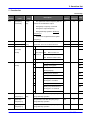
11. Monitoring
11.
Monitoring
11.1
Operating status monitoring
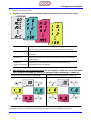
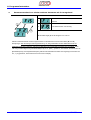
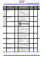
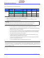
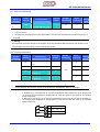
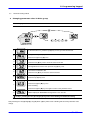
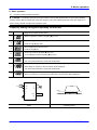
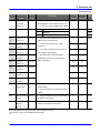
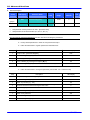
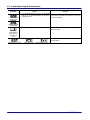
Output current
Group
LED Display
Drive group
CUr
Set
Min/Max
Factory
value
range
default
Set
Min/Max
Factory
value
range
default
Description
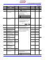
Output current
Unit
-
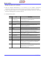
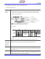
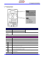
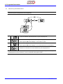
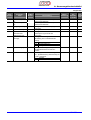
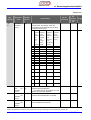
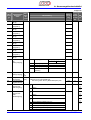
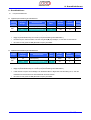
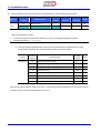
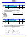
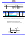
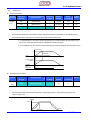
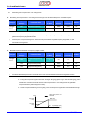
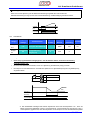
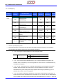
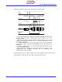
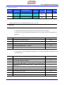
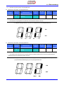
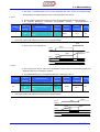
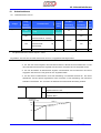
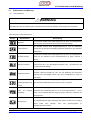
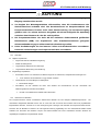
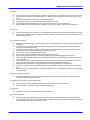
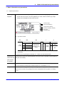
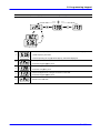
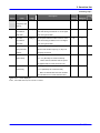
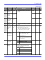
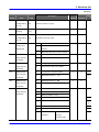
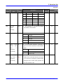
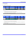
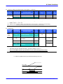
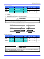
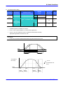
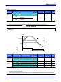
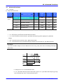
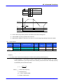
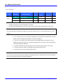
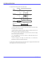
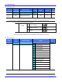
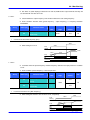
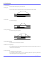
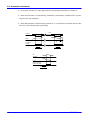
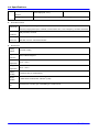
Inverter output current can be monitored in Cur.
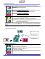
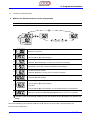
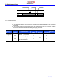
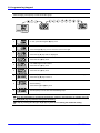
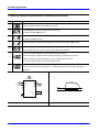
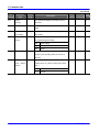
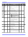
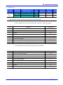
Motor RPM
Group
LED Display
Description
Unit
Drive group
rPM
[Motor RPM]
-
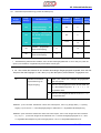
Function
H31
[Number of motor poles]
-
2/12
4
group 2
H40
[Control mode select]
-
0/2
0
H74
[Gain for Motor rpm display]
-
1/1000
100
%
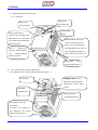
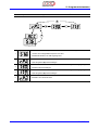
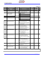
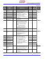
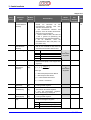
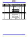
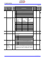
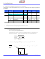
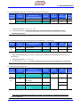
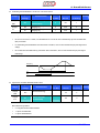
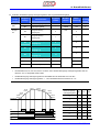
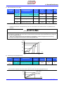
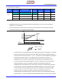
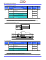
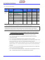
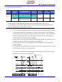
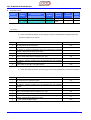
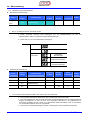
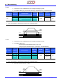
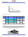
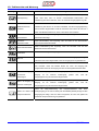
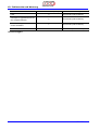
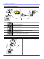
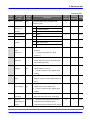
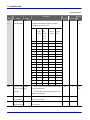
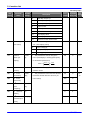
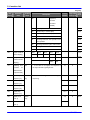
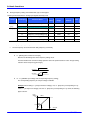
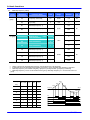
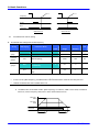
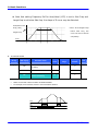
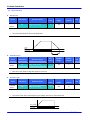
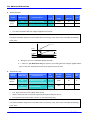
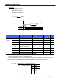
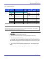
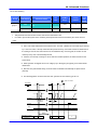
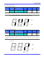
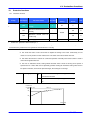
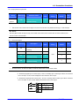
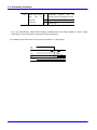
Motor rpm can be monitored in rPM.
When H40 is set to 0 {V/F control} or 1 {PID control}, the Inverter output frequency (f) is displayed in
RPM using the formula below. Motor slip is not considered.
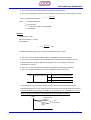
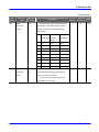
⎛ 120 × f ⎞ H 74
RPM = ⎜
⎟×
⎝ H 31 ⎠ 100
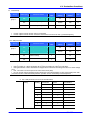
H31 : Enter the number of rated motor poles on the nameplate.
H74 : This parameter is used to change the motor speed display to rotating speed
(r/min) or mechanical speed (m/mi).
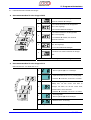
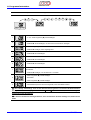
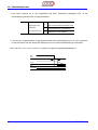
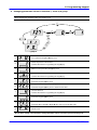
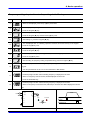
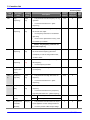
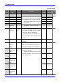
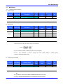
Inverter DC Link Voltage
Group
LED Display
Drive group
dCL
Set
Min/Max
Factory
value
range
default
Parameter Name
[Inverter DC Link Voltage]
Unit
-
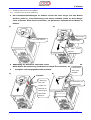
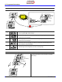
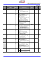
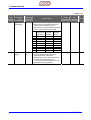
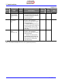
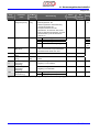
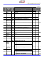
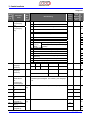
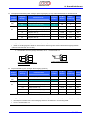
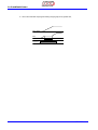
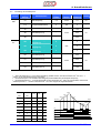
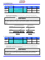
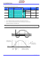
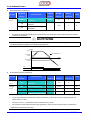
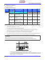
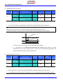
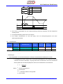
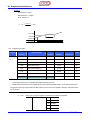
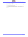
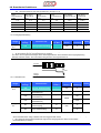
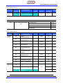
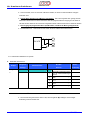
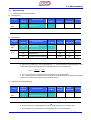
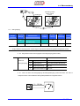
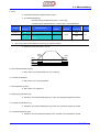
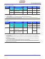
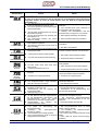
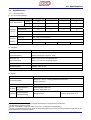
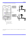
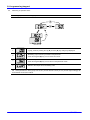
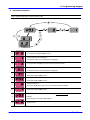
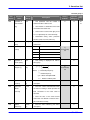
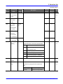
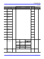
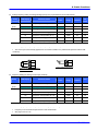
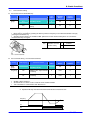
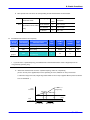
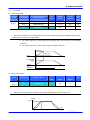
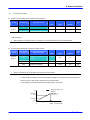
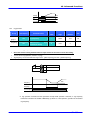
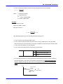
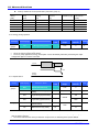
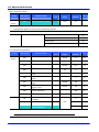
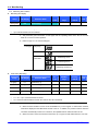
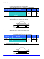
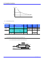
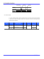
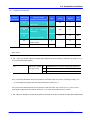
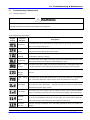
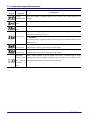
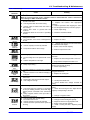
Inverter DC link voltage can be monitored in dCL.
2 times the value of input voltage is displayed while motor is at a stop.
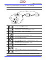
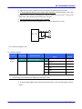
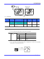
It is the voltage detected between P1 and N terminal of power terminal.
11-1
SV-iC5