1
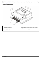
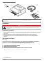
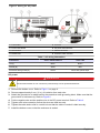
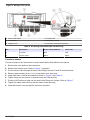
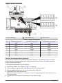
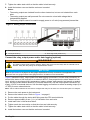
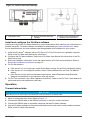
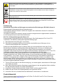
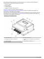
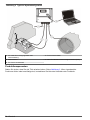
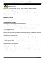
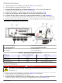
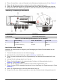
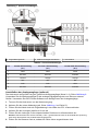
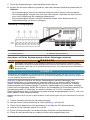
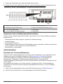
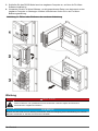
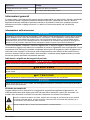
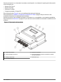
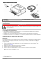
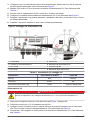
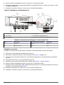
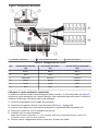
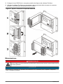
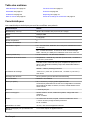
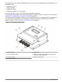
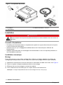
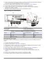
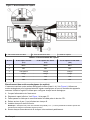
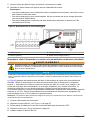
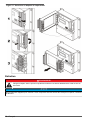
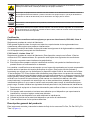
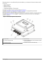
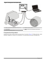
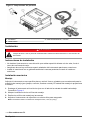
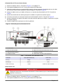
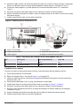
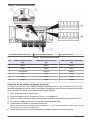
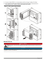
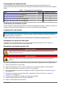
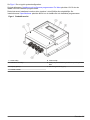
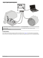
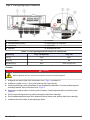
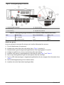
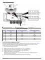
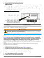
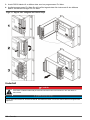
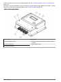
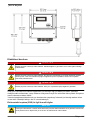
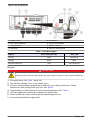
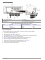
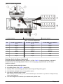
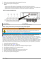
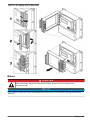
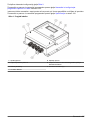
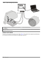
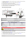
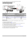
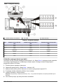
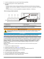
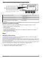
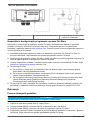
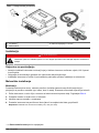
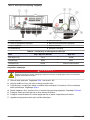
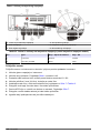
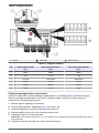
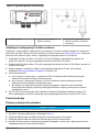
Figure 6 Wiring for DC power
1 Power reset button
4 Positive wire
2 Ground wire
5 DC power terminal
3 Negative wire
6 Protective earth grounding block
Table 2 DC wiring information (DC models only)
Pin
Description
Color—North America
Color—EU
1
+12 VDC
Red
Red
2
12 VDC return
Black
Black
Connect a sensor
Connect a sensor to the instrument to control and transmit flow data from the sensor.
1.
2.
3.
4.
5.
6.
7.
8.
9.
Remove the main power to the instrument.
Remove the bottom cover. Refer to Figure 1 on page 6.
Put the sensor cable through the strain relief fitting near the S1 and S2 terminal blocks.
Remove approximately 6 mm (¼ in.) of insulation from each wire.
Install each wire in the terminal block as shown in Figure 7 and Table 3.
Tighten each wire connection so that the wires are held securely.
Push the APR reference tube into the strain relief fitting until it stops. Refer to Figure 7.
Tighten the cable strain relief so that the cable is held securely.
Install the bottom cover so that the enclosure is sealed.
12 English