1
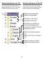
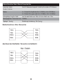
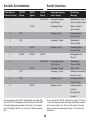
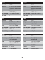
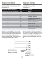
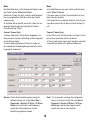
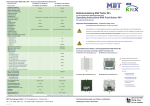
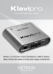
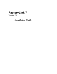
netNODE
Hardwarebeschreibung
Installationsanleitung
Hardware Description
Installation Instructions
Hilscher Gesellschaft für
Systemautomation mbH
Rheinstrasse 15
65795 Hattersheim
Germany
Phone: +49 (0) 6190 9907-0
Fax:
+49 (0) 6190 9907-50
E-Mail: [email protected]
Web: www.hilscher.com
Bitte beachten:
Windows 95/98/ME und Windows NT/2000/CE/XP sind
eingetragene Warenzeichen der Microsoft Corporation.
Please notice:
Windows 95/98/ME and Windows NT/2000/CE/XP are
registered trademarks of Microsoft Corporation.
Inhaltsverzeichnis
Table of Contents
Kurzbeschreibung. . . . . . . . . . . . . . . . . . . . . 4
Verzeichnisstruktur der CD . . . . . . . . . . . . . 5
CD-Inhalt . . . . . . . . . . . . . . . . . . . . . . . . . . . . 6
Systemvoraussetzungen . . . . . . . . . . . . . . . 7
Installation des netNODEs . . . . . . . . . . . . . 7
Gerätezeichnung . . . . . . . . . . . . . . . . . . . . . . 8
Die Tastatur . . . . . . . . . . . . . . . . . . . . . . . . . . 9
Der DIP-Schalter . . . . . . . . . . . . . . . . . . . . . . 9
Ethernet-Schnittstelle . . . . . . . . . . . . . . . . 10
Serielle Schnittstelle(n) . . . . . . . . . . . . . . . 12
Diagnoseschnittstelle . . . . . . . . . . . . . . . . 14
Installation der Software . . . . . . . . . . . . . . 15
Installation SyCon . . . . . . . . . . . . . . . . . . . . 16
Installation iCon-L . . . . . . . . . . . . . . . . . . . 16
Installation des IP Treibers. . . . . . . . . . . . . 17
Konfiguration des IP Treibers . . . . . . . . . . 17
Aufrufen des TCP/UDP IP Treibers . . . . . . 19
Einstellen der IP-Adresse . . . . . . . . . . . . . . 20
Konfiguration des netNODE . . . . . . . . . . . 22
Fehlersuche . . . . . . . . . . . . . . . . . . . . . . . . 23
Diagnose über das Display . . . . . . . . . . . . 24
Technische Daten netNODE 40 / 42 . . . . . . 25
Description . . . . . . . . . . . . . . . . . . . . . . . . . . 4
Directory Structure of the CD. . . . . . . . . . . . 5
CD Content . . . . . . . . . . . . . . . . . . . . . . . . . . 6
System Requirements . . . . . . . . . . . . . . . . . 7
Installation netNODE . . . . . . . . . . . . . . . . . . 7
Device Drawing . . . . . . . . . . . . . . . . . . . . . . . 8
The Keys . . . . . . . . . . . . . . . . . . . . . . . . . . . . 9
The DIP Switch . . . . . . . . . . . . . . . . . . . . . . . 9
Ethernet Interface . . . . . . . . . . . . . . . . . . . . 10
Serial Interface(s) . . . . . . . . . . . . . . . . . . . . 12
Diagnostic Interface . . . . . . . . . . . . . . . . . . 14
Installation Software . . . . . . . . . . . . . . . . . 15
Installation SyCon . . . . . . . . . . . . . . . . . . . . 16
Installation iCon-L . . . . . . . . . . . . . . . . . . . . 16
Installation of the IP Driver. . . . . . . . . . . . . 17
Configuration of the IP Driver . . . . . . . . . . 17
Using the TCP/UDP IP Driver . . . . . . . . . . . 19
Set the IP Address. . . . . . . . . . . . . . . . . . . . 20
Configuration of netNODE . . . . . . . . . . . . . 22
Troubleshooting . . . . . . . . . . . . . . . . . . . . . 23
Diagnostic via the Display . . . . . . . . . . . . . 24
Technical Data netNODE 40 / 42 . . . . . . . . 25
Revision 2.1
3
Kurzbeschreibung
Description
Der netNODE ist ein Ethernet Gateway. Es ist modular
aufgebaut und bietet neben einer Ethernet Schnittstelle
bis zu drei serielle Schnittstellen.
The netNODE is an Ethernet Gateway. It is modularly
structured and offers in addition to an Ethernet interface
up to three serial interfaces.
Das eingebaute Display zusammen mit den CursorTasten erlauben eine Parametrierung und Inbetriebnahme vor Ort ohne weitere Hilfsmittel.
The built-in display together with the cursor keys permit
parameterisation and start-up without any additional
tools.
Alternativ kann die Parametrierung und Inbetriebnahme
mittels des Systemkonfigurators SyCon über einen PC
erfolgen, der über die serielle Diagnoseschnittstelle
oder das Ethernet-Netzwerk angeschlossen wird.
Alternatively the parameterisation and start-up can be
done with the System Configurator SyCon via a PC,
which is connected by the serial diagnostic interface or
the Ethernet network.
Die Gateway-Funktion besteht aus einem transparenten
Austauschen der Protokolldaten über ein TCP/IP-Telegramm. Für Applikationen mit weitergehenden Anforderungen lässt sich der Funktionsumfang mit Hilfe des
grafischen Programmiersystems iCon-L leicht erweitern, womit ohne weitergehende Programmierkenntnisse die Messages (die Sende-und Empfangstelegramme
werden geräteintern als Message dargestellt) anhand
von Bausteinen vom Anwender selbst bearbeitet werden können.
The Gateway function consists of a transparent exchange of the protocol data via a TCP/IP telegram. Applications that extend beyond this range can be easily impemented with the aid of the graphical programming
system iCon-L with which the user is able to process
messages (Send- and receive telegrams are displayed
as message device internal) with graphical function
blocks without programming knowledge.
Zur Installation, Konfiguration und Bedienung des netNODE gibt es weitere Manuals. Diese finden Sie ebenfalls auf der netDEVICEs System Software CD. Folgende Manuals sind vorhanden:
There are further manuals for installation, configuration
and operating with the netNODE. This manuals you
also find on the netDEVICEs System Software CD. The
following manuals are available:
netNODE
für netNODE 40/42
Inbetriebnahmeleitfaden und Bedienungsanleitung für netNODE Geräte
netNODE
for netNODE 40/42
start-up guide and operating instruction for
netNODE devices
SyConND
Systemkonfigurator netDEVICE
Konfiguration und Diagnose mit dem
Systemkonfigurator SyCon
SyConND
System Configurator netDEVICE
Configuration and Diagnostic with the
System Configurator SyCon
4
Verzeichnisstruktur der CD
Directory Structure of the CD
Sie erhalten auf dieser CD alle Dokumentationen im
Adobe-Acrobat-Reader-Format (PDF). Im Verzeichnis
ACROREAD ist eine Runtime-Version enthalten.
All manuals on this CD are delivered in the Adobe
Acrobat Reader format (PDF). A runtime version of this
reader can be found in the ACROREAD directory.
Installation des Acrobat Readers
Installation of Acrobat Reader
Dokumentation zu den Treibern
Dokumentation for the Drivers
Dokumentation zum netNODE und
SyCon im Acrobat Reader Format
Documentation of netNODE and SyCon
in Acrobat Reader format
Installation des Systemkonfigurators
SyCon
Installation of the System ConfiguratorSyCon
Installation des Hilscher IP Treibers
Installation of the Hilscher IP Driver
5
CD-Inhalt
CD Content
• ladbare Firmware*
• Hilscher TCP/UDP IP Treiber
• Systemkonfigurator SyCon
• iCon-L**
• die Dokumentation
• loadable Firmware*
• Hilscher TCP/UDP IP Driver
• System Configurator SyCon
• iCon-L**
• Documentation
für unsere netNODE Gateways.
for our netNODE Gateways.
Die Erstinbetriebnahme erfolgt durch den Systemkonfigurator SyCon. Dazu ist eine serielle Verbindung zwischen der Diagnoseschnittstelle des netNODEs und
dem COM-Port des PCs herzustellen. Das hierfür verwendetet Kabel trägt die Bezeichnung CAB-NN.
The initial start-up takes place via the System Configurator SyCon. For this it is necessary to built up a serial
connection between the diagnostic interface of the netNODE and the COM-Port of the PC. The cable which is
used for this has the designation CAB-NN.
Mit dem Systemkonfigurator SyCon ist dann
• die Firmware
• die Konfiguration (incl. IP-Adresse) sowie
• die Grundgatewayfunktion (Image Datei)
in den netNODE zu laden.
With the System Configurator SyCon
• the firmware
• the configuration (incl. IP Address) as well as
• the basic gateway function (Image file)
has to be loaded in the netNODE.
Eine Konfiguration und Diagnose ist nun auch über das
netNODE Display mittels der Cursortasten möglich. Die
Konfiguration wird auf dem Gateway gespeichert, so
dass dieses beim Starten sofort betriebsbereit ist.
A configuration and diagnostic is now also possible via
the netNODE display by means of the cursor keys. The
configuration is stored on the Gateway, therefore it is
immediately ready for operation after the start.
Alternativ kann vom SyCon die Konfiguration bzw. Diagnose über eine TCP/IP Verbindung zum net durchgeführt werden.
Alternatively the configuration and diagnostic can be
done via a TCP/IP connection to the netNODE.
* Falls es eine neue Firmwareversion gibt, können Sie
diese von unserer Homepage herunterladen.
* If there are new firmware versions available you can
download it from our homepage.
** Zum Betrieb der lizensierten Version der Bausteinbibliothek iCon-L benötigen Sie einen Lizenzcode.
Wenn dieser im Lieferumfang mit enthalten ist, finden
Sie ihn als Label auf dieser CD. Andernfalls wenden
Sie sich bitte an Ihren Distributor oder direkt an uns.
** A license code is required to use the licensed version
of the module library iCon-L. If this is included in the
scope of delivery you will find it on a label on this CD.
Otherwise please call your distributor or us directly.
6
Systemvoraussetzungen
System Requirements
• PC mit 586-, Pentium-Prozessor oder höher
• Windows 98/ME, Windows NT 4.0/2000/XP
• Freien Festplattenspeicher: 30 - 80 MByte
• CD-ROM-Laufwerk
• RAM: mind. 16 MByte
• Grafikauflösung: mind. 800 x 600 Bildpunkte
• Windows NT: Service Pack 3 oder höher
• Tastatur und Maus
• PC with 586-, Pentium processor or higher
• Windows 98/ME, Windows NT 4.0/2000/XP
• Free disk space: 30 - 80 MByte
• CD ROM drive
• RAM: min. 16 MByte
• Graphic resolution: min. 800 x 600 pixel
• Windows NT: Service Pack 3 or higher
• Keyboard and Mouse
Installation des netNODEs
Installation netNODE
Das netNODE wird auf eine Tragschiene nach DIN EN
50022 befestigt und mit 24 V Betriebsspannung versorgt.
The netNODE is mounted on a DIN rail according to
DIN EN 50022 and it is supplied with an operating voltage of 24 V.
Die Erdung erfolgt über den Erdungskontakt zur Hutschiene an der Rückseite des Geräts.
The grounding is made by the earth terminal to the DIN
rail at the back side of the device.
Typ
Ethernet Schnittstelle
Serielle Schnittstelle
Type
Ethernet Interface
Serial Interface
netNODE 40
1 Schnittstelle / 1 Interface
1 Schnittstelle / 1 Interface
netNODE 42
1 Schnittstelle / 1 Interface
3 Schnittstellen / 3 Interfaces
An den seriellen Schnittstellen des netNODE 40 und
des netNODE 42 ist RS232C, RS422 und RS485 möglich.
On the serial interfaces of netNODE 40 and netNODE
42 RS232Cs, RS422 and RS485 are possible.
7
Gerätezeichnung
Device Drawing
Anschlüsse Betriebsspannung
X5
1. serielle Schnittstelle / 1. serial Interface
COM 1
Connections power supply
X4
2. serielle Schnittstelle / 2. serial Interface
COM 2
Ground
X3
3. serielle Schnittstelle / 3. serial Interface
COM 3
24 V
Hinweis: Die seriellen Schnittstellen X3 und X4 sind
nur bei netNODE 42 Geräten vorhanden. Bei netNODE
40 gibt es nur die serielle Schnittstelle X5. Die Schnittstelle X2 ist für zukünftige Erweiterungen vorgesehen
und ist derzeit nicht vorhanden.
Note: The serial interfaces X3 and X4 are only available for netNODE 42 devices. For netNODE 40 just the
serial interface X5 exists. The interface X2 is reserved
for future use.
8
Die Tastatur
The Keys
Das eingebaute Display zusammen mit den Cursor
Tasten erlauben eine Parametrierung und Inbetriebnahme des netNODE Gerätes ohne weitere Hilfsmittel. Voraussetzung dazu ist, dass bereits die Firmware, eine
Konfiguration und die Gatewayfunktion (Image Datei) in
das netNODE geladen wurde.
Die Cursor Tasten des netNODEs sind:
Mit den Tasten Up und Down kann man
zwischen den verschiedenen Hauptmenüs wechseln.
Left
Die Tasten Right und Left werden verwendet, um in den Untermenüs Parameter zu editieren.
Mit der Taste ESC verlässt man das
aktuelle Menü und kehrt in das übergeordnete Menü zurück.
Mit der Taste OK wechselt man in das
im Display angezeigte Untermenü.
Die Beschreibung der Menüstruktur finden Sie im
Bedienermanual netNODE auf der netDEVICEs CD im
Verzeichnis CD:\Manuals\Deutsch\netNODE_de.pdf.
The built-in display together with the cursor keys permit
parameterisation and start-up without any additional
aids. A condition for it is that the firmware, a configuration and the gateway function (image file) were already
loaded into the netNODE.
Up
The cursor keys of the netNODE are:
With the keys Up and Down you can
change between the different main
Right
menus.
The keys Right and Left are used for
processing the parameter in the submenus.
With the ESC key you leave the actual
Down menu and change in the higher menu.
With the OK key you change in the
submenu which is shown in the display.
The description of the menu structure you find in the
operating manual netNODE on the netDEVICEs CD in
the directory CD:\Manuals\English\netNODE_en.pdf.
Der DIP-Schalter
The DIP Switch
Der DIP-Schalter wird verwendet, um die AbschlussWiderstände der seriellen Schnittstelle X5 (1. serielle
Schnittstelle) ein- bzw. auszuschalten.
Sind alle Schalter auf OFF geschaltet, ist keine Terminierung vorhanden. Sind die Schalter alle auf ON
geschaltet, ist eine Terminierung für RS422 bzw. RS485
vorhanden.
Bei eingeschalteter Terminierung beträgt der Terminierungswiderstand 120 Ohm. Auch die Pullup/Pulldown
Terminierung ist mit 470 Ohm ebenfalls aktiv.
The DIP Switch is used to switch the termination resistors of the serial interface X5 (1. serial interface) on
and off.
If all switches are turned to OFF no termination exists. If
the switches are turned to ON there is termination for
RS422 and respectively RS485.
If the termination is switched on, the termination resistance is 120 ohm. Also the pullup/pulldown termination
with 470 ohm is active.
DIP-Schalter auf ON
geschaltet (Schalter sind
alle oben)
DIP Switch is ON (all
switches are at the top)
DIP-Schalter auf OFF
geschaltet (Schalter sind
alle unten)
DIP Switch is OFF (all
switches are at the bottom)
9
Ethernet-Schnittstelle
Ethernet Interface
Ethernet Kabelbelegung am RJ45-Stecker.
Ethernet cable connection to the RJ45 plug.
Anschluss mit RJ45 Stecker
Signal
Connection with RJ45 plug
Signal
Bedeutung
Meaning
1
TXD+
Sendetaten + / Transmitt Data +
2
TXD-
Sendedaten - / Transmitt Data -
3
RXD+
Empfangsdaten + / Receive Data +
4
-
unbenutzt / not used
5
-
unbenutzt / not used
6
RXD-
Empfangsdaten - / Receive Data -
7
-
unbenutzt / not used
8
-
unbenutzt / not used
Für die Ethernet Schnittstelle verwendet man RJ45
Stecker und Twisted Pair Kabel, welches aus 4 paarweise verdrillten Adern besteht.
For the Ethernet interface you use RJ45 plugs and Twisted Pair cable which consists of 4 twisted cores.
Man unterscheidet zwischen STP (geschirmtes Twisted
Pair) und UTP (ungeschirmtes Twisted Pair). Der Unterschied zwischen geschirmt und ungeschirmt ist, dass
bei UTP nur ein Schirm um das gesammte Kabel
besteht. Bei STP ist jedes Adernpaar innerhalb des
Kabels nochmals einzeln geschirmt.
You can distinguish between STP (shielded Twisted
Pair) and UTP (unschielded Twisted Pair). The difference between shielded and unshielded is, that in case of
UTP only one shield is around the whole cable. In case
of STP each core pair is shielded separately.
Als Übertragungsmedium wird Twisted Pair Kabel der
Kategorie 3 oder 5 verwendet, welches eine Übertragungsrate von 10 bzw. 100 MBit/s hat.
As transmission medium Twisted Pair cable category 3
or 5 is used which has a transmission rate of 10 and
respectively 100 MBit/s.
Es wird die Verwendung von Kategorie 5 Kabeln empfohlen.
It is recommended to use cable of category 5.
10
Ethernet Anschluss Daten / Ethernet Connection Data
Anzahl der Geräte /
Durch IP-Adressraum begrenzt / limited by the number of IP Addresses
Number of devices
Medium
4 x 2 Twisted Pair Kupferkabel Kat 3 (10 MBit/s), Kat 5 (100 MBit/s) /
Leitungslänge / Length of cable
zum Hub oder Switch max. 100m / to Hub or Switch max. 100m
4 x 2 Twisted Pair copper cable Cat 3 (10 MBit/s), Cat 5 (100 MBit/s)
Übertragungsrate / Transmission rate 10 MBit/s
Topologie / Topology
Sternförmige Verkabelung / Star Topology
Direkter Anschluss / Direct Connection
TXD+
TXDRXD+
RXD-
TXD+
TXDRXD+
RXD-
Anschluss über Hub/Switch / Connection via Hub/Switch
Hub / Switch
TXD+
TXDRXD+
RXD-
TXD+
TXDRXD+
RXD-
11
Serielle Schnittstelle
Serial Interface
DSub-Stecker
RS232C
RS422
RS485
Eingang/Ausgang
Connector male
Signal
Signal
Signal
Input /output
Meaning
1
-
-
RxD/TxD-N
Eingang/Ausgang
Sendedaten invertiert
Input/Output
Transmit data inverted
TxD-N
Ausgang/Output
Bedeutung
Daten invertiert /
data inverted
2
RxD
-
-
Eingang / Input
Empfangsdaten /
3
TxD
-
-
Ausgang / Output
Sendedaten /
4
-
RxD-P
-
Eingang / Input
Empfangsdaten /
5
RGND
RGND
RGND
6
-
-
Receive Data
Transmit Data
Receive Data
Bezugspotential /
Ground
RxD/TxD-P
TxD-P
Eingang/Ausgang
Sendedaten /
Output/Input
Transmit Data
Ausgang / Output
Daten / Data
7
RTS
-
-
Ausgang / Output
Sendeteil einschalten
8
CTS
-
-
Eingang / Input
Sendebereitschaft
9
-
RxD-N
-
Eingang / Input
Ready to Send
Clear to Send
Empfangsdaten
invertiert
Receive Data
inverted
Bei Verwendung der RS232 Schnittstelle muss das Signal CTS (Pin 8 - Sendebereitschaft) aktiviert, dass heißt
auf High-Pegel gelegt werden. Dies kann zum Beispiel
durch Verbinden der Pins 4, 6 und 8 im Stecker geschehen.
In the case of the RS232 interface the signal CTS (pin 8
- Clear to Send) must be activated, that means it need
to be set on High Level. This can take place for example by means of connecting the pins 4, 6 and 8 in the
connector.
12
RS232C
RS232C
Schnittstelle
RS232C
Interface
RS232C
Verwendung
für Punkt-zu-Punkt-Verbindungen
Using
for point to point connections
zwischen zwei Kommunikations-
between two communication
geräten
devices
Kabel
LIYCY 3 x 0,25 qmm
Cable
LIYCY 3 x 0,25 qmm
max. Kabellänge
15 m (bei max. 19,2 kBit/s)
max. Cable Length
15 m (for max. 19.2 kBit/s)
max. Geräte
2
max. Devices
2
RS422
RS422
Schnittstelle
RS422
Interface
RS422
Verwendung
Bus (Multipunkt) oder Punkt-zu-
Using
Bus (multipoint) or for point to
Kabel
LIYCY 2 x 2 x 0,25 qmm
Cable
LIYCY 2 x 2 x 0,25 qmm
max. Kabellänge
1200 m (bei max. 19,2 kBit/s)
max. Cable Length
1200 m (at max. 19.2 kBit/s)
Wellenwiderstand
100-150 Ohm
Wave Resistance
100-150 Ohm
Kapazitätsbelag
ca. 60 pF/m
Capacity
ca. 60 pF/m
Punkt-Verbindungen
point connections
RS485
RS485
Schnittstelle
RS485
Interface
RS485
Verwendung
Bus (Multipunkt) oder Punkt-zu-
Using
Bus (multipoint) or for point to
Kabel
LIYCY 2 x 2 x 0,25 qmm abge-
Cable
LIYCY 2 x 2 x 0.25 qmm
Wellenwiderstand
100-120 Ohm
Wave Resistance
100-120 Ohm
Kapazitätsbelag
ca. 60 pF/m
Capacity
ca. 60 pF/m
max. Geräte
32 (ohne Repeater)
max. Devices
32 (without Repeater)
Punkt-Verbindungen
point connections
schirmtes, verdrilltes Kabel
shielded, twisted cable
13
Diagnoseschnittstelle
Diagnostic Interface
Potentialfreie RS232C zum Anschluss an die COMSchnittstelle des PCs.
Isolated RS232C to connect with the
COM port of the PC.
Anschluss mit 9 poligem DSub-Stecker
Signal
Connection with 9 pin DSub male connector
Signal
Bedeutung
Meaning
1
-
unbenutzt / not used
2
RxD
3
TxD
Sendedaten / Send Data
4
DTR
Datenendeinrichtung betriebsbereit
5
GND
Betriebserde / Signal Ground
Empfangsdaten / Receive Data
Data Terminal Ready
6
-
7
RTS
unbenutzt / not used
Sendeteil einschalten / Ready to Send
8
CTS
Sendebereitschaft / Clear to Send
9
-
unbenutzt / not used
Hinweis: Für die Verbindung des PCs mit der Diagnoseschnittstelle des netNODEs wird ein spezielles Kabel
der Firma Hilscher benötigt. Bei diesem Kabel befindet
sich die für die Verbindung benötigte Elektronik im
Anschluss-Stecker des Kabels. Die Bestellbezeichnung
für das netNODE Diagnose-Kabel ist CAB-NN.
Note: You need a special cable from the company Hilscher to connect the PC with the diagnostic interface of
the netNODE. By this cable the used electronic for the
connection is inside the plug of the cable. The order
designation for the netNODE diagnostic cable is CABNN.
14
Installation der Software
Software Installation
Schließen Sie alle Programme!
Close all application programs on the system!
Legen Sie die netDEVICE CD in das lokale CD-ROMLaufwerk.
Das Installationsprogramm startet selbständig
(Autostart eingeschaltet). Andernfalls wechseln Sie
in das Root Verzeichnis der CD und starten Sie
Autorun.exe (Autostart ausgeschaltet).
Insert the netDEVICE CD in the local CD ROM drive.
The installation program will start by itself (Autostart
enabled). Otherwise change into the root directory of
the CD and start Autorun.exe (Autostart disabled).
HINWEIS Unter Windows NT/2000/XP benötigen Sie
Administratorrechte zur Installation!
NOTE Administrator privileges are required on
Windows NT/2000/XP systems for installation!
Das Installationsprogramm fragt, welche Komponenten
installiert werden sollen. Beantworten Sie diese Fragen
mit Ja bzw. Nein.
The installation program ask for the components you
want to install. Answer these questions with Yes or No.
Es können installiert werden
It can be installed
• Systemkonfigurator SyConND
• iCon-L
• Hilscher IP Treiber.
• System Configurator SyConND
• iCon-L
• Hilscher IP Driver.
Für den Systemkonfigurator SyConND wird keine
Lizenz benötigt, da die Basisversion alle Funktionen
zum Betrieb des netNODE beinhaltet.
For the System Configurator SyCon no license code is
required because the basic version includes all functions for the operation of the netNODE.
Wenn Sie einen Lizenzcode für iCon-L haben oder ein
Lizenzcode auf der CD angegeben ist, dann beantworten Sie die Frage nach einem vorhandenen Lizenzcode
mit Ja. Geben Sie weiter Ihren Namen und den Firmennamen ein.
Beantworten Sie die Frage nach einem Lizenzcode mit
Nein, wird die Basisversion des iCon-L installiert.
If you have a license code for iCon-L or a license code
is labeled on the CD, then answer the question for an
existing license code with Yes. Further enter your name
and the company name.
If you answer the question for a license code with No,
the basic version of iCon-L will be installed.
Folgen Sie den Anweisungen des Installationsprogrammes und beantworten die Fragen mit JA oder WEITER.
Follow the instructions of the installation program and
answer all the questions with OK or NEXT.
15
Installation SyCon
Installation of SyCon
Bei der Frage nach dem Lizenzcode wählen Sie bitte
das Feld Nein an, da keine Lizenz benötigt wird. Es
wird die Basisversion des Systemkonfigurators installiert, die alle Funktionen zum Betrieb des netNODE enthält.
With the question about the license code please select
the field No, because no license is needed. The basic
version of the System Configurator is installed, which
contains all functions for operating the netNODE.
Installation iCon-L
Installation iCon-L
Bei der Installation der lizensierten Version von iCon-L
müssen Sie Ihren Namen und den Firmennamen eingeben. Wenn Sie einen Lizenzcode haben oder dieser auf
der CD angegeben ist, dann geben Sie diesen bitte jetzt
ein.
Wenn Sie keinen Lizenzcode haben, arbeitet die Bausteinbibliothek iCon-L nur als Basisversion.
During the installation of the licensed version of iCon-L
you have to type in the user and the company name. If
you have a license code or it is labled on the CD, it
must also be entered now.
If you have no license code, the module library iCon-L
will work as a basic version.
Sie haben auch die Möglichkeit einen Lizenzcode für
iCon-L nachträglich zu bestellen. Unter dem Menüpunkt
Hilfe > Lizensierung im Systemkonfigurator können
Sie ein Bestellformular für Ihre Lizenz ausfüllen und an
Ihren Distributor oder direkt an uns faxen.
You also have to possibility to order a license code for
iCon-L subsequently. With the menu item Help > Licensing in the System Configurator you can fill out an
order form and send it to your distributor or directly to
us.
Die Basisversion des iCon-L hat folgenden Funktionsumfang:
• Vorhandene Projekte öffnen, Parameter von Bausteinen ändern und in den netNODE laden
• Diagnosefunktionen für vorhandene Projekte
• Bausteine können nicht entfernt bzw. hinzugefügt
werden!
The basic version of iCon-L has the following scope of
functions:
• Open extisting projects, change parameter of modules and load it into the netNODE
• Diagnostic functions for exsting projects
• Modules can not be deleted or added!
Die lizensierte Version des iCon-L hat folgenden Funktionsumfang
• Projekte mit bis zu 100 Bausteinen erzeugen
• Projekte neu anlegen und vorhandenen öffnen, Parameter von Bausteinen ändern und in den netNODE
laden
• Diagnosefunktionen
• Bausteine können entfernt und hinzugefügt werden
The licensed version of iCon-L has the following scope
of functions:
• Produce projects with up to 100 modules
• Create new projects and open existing projects, change parameter of the modules and load it into the netNODE
• Diagnostic functions
• Modules can be deleted or added
16
Installation des IP-Treibers
Installation of the IP Driver
Wählen Sie Hilscher IP Treiber aus dem Installationsmenü oder starten Sie aus dem CD Verzeichnis
\TcpUdpIp Driver das Programm IpDrvSetup.exe.
Select Hilscher IP Driver in the installation menu or
start the program IpDrvSetup.exe from the CD directory \TcpUdpIp Driver.
Nach der Installation muss der Hilscher IP Treiber entsprechend dem netNODE konfiguriert werden. Das
heißt, es müssen die IP Adresse und die Port Nummer
des netNODEs angegeben werden, wie im nächsten
Abschnitt beschrieben.
After the installation the Hilscher IP Driver has to be
configured according to the netNODE. That means you
have to type in the IP address and the Port number of
the netNODE, as described in the next section.
Konfiguration des
IP-Treibers
Configuration of the
IP Driver
Starten Sie das Konfigurationsprogramm des Hilscher
IP Treibers mit Start > Programme > Hilscher IP Driver > IP Driver Setup.
Start the configuration program of the Hilscher IP Driver
with Start > Programs > Hilscher IP Driver > IP Driver
Setup.
Geben Sie die konfigurierte IP-Adresse des netNODE
in das Feld IP-Address sowie die Port Nummer in das
Feld Port ein (Um den netNODE eine IP-Adresse zuzuweisen, lesen Sie Abschnitt ‘Einstellen der IP-Adresse’
auf Seite 20). Abweichend von den Standardeinstellungen können noch folgende Änderungen vorgenommen
werden:
Enter the configured IP Address of the netNODE in the
field IP Address and the Port number in the field Port
(To assign an IP Address to the netNODE, read section
‘Set the IP Address’ at page 20). Deviating from the
standard settings the following changes can also be
made:
Port:
Arbeitet der Treiber im Client Modus, muss hier die
Portnummer des netNODE angegeben werden unter
der das Gerät angesprochen werden kann.
Arbeitet der Treiber als Server, wird hier der Port angegeben auf welchem der Treiber auf eingehende Verbindungen vom netNODE wartet (Grundeinstellung: 1099,
Treiber arbeitet als Client).
Port:
If the driver works in Client mode, you have to set here
the Port number under which the device can be addressed.
If the driver works as Server, here the Port number is
given, on which the driver waits for a receiving connection from the netNODE (Default setting: 1099, driver
works as Client).
Protocol:
Hier kann parameteriert werden, mit welchem Protokoll
die Kommunikation stattfinden soll, TCP/IP oder
UDP/IP. Als Grundeinstellung ist TCP/IP ausgewählt.
Protocol:
Here you can parameterize with which protocol the
communication should take place, TCP/IP or UDP/IP.
As default setting TCP/IP is selected.
17
Mode:
Das Feld Mode dient zur Einstellung des Modus in dem
der Treiber arbeitet (Client oder Server).
Arbeitet der Treiber als Client, wird der Verbindungsaufbau zum eingestellten Gerät aktiv durch den Treiber
vorgenommen.
Ist als Mode Server gewählt, wartet der Treiber auf eingehende Verbindungen des eingestellten Gerätes
(Grundeinstellung: Client).
Mode:
In the field Mode you can set in which mode the driver
works (Client or Server).
If the driver works as Client, the connection built up is
done active by the driver.
If the mode Server is selected, the driver waits for receiving connections of the set device (Default setting: Client).
Connect Timeout (ms):
In diesem Feld wird im Client Modus angegeben, wie
lange versucht wird eine Verbindung mit dem eingestellten Gerät herzustellen.
Im Server Modus gibt dieses Feld an, wie lange auf
eine eingehende Verbindung des parametrierten Gerätes gewartet werden soll.
Connect Timeout (ms):
In this field is set in the Client mode, how long it is tried
to built up a connection with the set device.
In Server mode it gives how long it should be waited for
a received connection of the paramerized device.
Hinweis: Wenn diese Einstellung später nochmals
geändert werden soll, ist das Menü Start >
Programme > Hilscher IP Driver > IP Driver
Setup erneut aufzurufen und Programme,
welche den Treiber benutzen, müssen
ebenfalls neu gestartet werden.
Note: If it is necessary to change the configuration
later on, you have to restart the menu Start >
Programs > Hilscher IP Driver > IP Driver
Setup again and also the programs which
use the driver have to be restarted.
18
Aufrufen des TCP/UDP IP
Treibers
Using the TCP/UDP IP
Driver
Von eigenen Windows Applikationen können Sie den
Treiber benutzen, um auf die Mailboxen bzw. das Prozesabbild (soweit vorhanden) des netNODE zuzugreifen.
From own Windows applications you can use the driver
to get access to the mailbox and/or the process data
image of the netNODE (if available).
Das Manual DRV_IP.PDF beschreibt alle Funktionen
des TCP/UDP IP Treibers. Die protokollspezifischen
Befehle und Datenstrukturen sind jeweils in einem eigenem Manual beschrieben. Wenn Sie einen eigenen
Treiber schreiben möchten, bieten wir eine Beschreibungen mit einer genauen Definition der Schnittstelle
(API) an.
The Manual DRV_IP.PDF describes all functions of the
TCP/UDP IP driver. The protocol specific commands
and data structures are described presenty in their own
manuals.
If you want to write your own driver, we provide a detailed description of the interface (API).
Inhalt / Subject
Programmieranleitung zum Hilscher IP Treiber
How to use the Hilscher IP Driver
Programmieranleitung zum Hilscher Device Treiber
How to use the Hilscher Device Driver
Protocol Interface Manual NetIdent
Protocol Interface Manual Protokolle
ASCII, 3946R, RK512, Modbus RTU
Die Protokoll Interface Manuals finden Sie auf der netDEVICE CD im Verzeichnis CD:\Api\Manuals\Pintface\...
Manual
DRV_IP.PDF
DEVDRV.PDF
NI_PIE.PDF
STD_PIE.PDF
The Protocol Interface Manuals are on the netDEVICE
CD in the directory CD:\Api\Manuals\Pintface\...
The DRV_IP.PDF and DEVDRV.PDF manuals you find
on the netDEVICE CD in the directory
CD:\Api\Manuals\Driver\....
Die Manuals DRV_IP.PDF und DEVDRV.PDF finden
Sie auf der netDEVICE CD im Verzeichnis
CD:\Api\Manuals\Driver\....
19
Einstellen der IP-Adresse
Set IP Address
Im Auslieferungszustand hat der netNODE die IPAdresse 0.0.0.0. Um eine IP-Adresse einzustellen ist im
Systemkonfigurator SyCon das Menü Einstellungen >
Gerätezuordnung > TCP/IP Driver > NetIdent Konfiguration aufzurufen. Alternativ kann auch Start > Programme > Hilscher IP Driver > NetIdent Demo Program verwendet werden.
On delivery the netNODE has the IP address 0.0.0.0.
To set an IP Address, you have to select the menu Settings > Device Assignment > TCP/IP Driver > NetIdent Configuration in the System Configurator SyCon.
Alternatively you can also use Start > Programs > Hilscher IP Driver > NetIdent Demo Program.
Mit der Schaltfläche Geräte finden/Start Poll wird das
Netzwerk nach Geräten (netDEVICEs) gescannt. Werden ein oder mehrere Geräte gefunden, werden diese
in der Liste mit ihrer MAC-ID angezeigt.
With the button Start Poll the network is scanned for
devices (netDEVICEs). If one or more devices were
found, they are shown with their MAC-ID in the list.
Hat das Gerät schon eine IP-Adresse wird diese im
Feld IP-Adresse angezeigt. Ist die angezeigte IPAdresse 0.0.0.0, muss dem Gerät mit der Schaltfläche
IP-Adresse setzen/SetIP eine Adresse zugewiesen
werden. Zum manuellen Ändern einer vorhandenen IPAdresse markiert man das Gerät in der Liste und wählt
die Schaltfläche IP-Adresse setzen/SetIP.
If the device already has an IP Address this is shown in
the field IP Address. If the shown IP Address is 0.0.0.0,
an IP Address has to be assigned to the device with the
button SetIP.
For manual changing of an existing IP address you
have to mark the device in the list and then select the
SetIP button.
Wenn die IP-Adresse eingegeben ist, bestätigt man in
diesem Fenster mit der Schaltfläche IP-Adresse setzen/SetIP, um dem netNODE diese Adresse zuzuweisen.
If the IP Address is entered, you confirm in this window
with the button SetIP to assign this address to the netNODE.
20
Hinweis: Diese IP Adresse ist nur temporär eingestellt.
Eine permanente Speicherung der IP-Adresse erfolgt
erst mit dem Systemkonfigurator SyCon, wie im
Abschnitt ‘Konfiguration des netNODE’ beschrieben.
Note: This IP Address is only temporarly adjusted. A
permanent storage of the IP Address takes place only
with the System Configurator SyCon, as described in
section ‘Configuration of the netNODE’.
Hinweis: Zum Einstellen der IP-Adresse muss sich das
netNODE im gleichen Ethernet Netzwerk (Subnetzwerk) wie der verwendete PC befinden.
Note: To set the IP Address the netNODE has to be in
the same Ethernet network (Sub network) as the used
PC.
21
Konfiguration des netNODE
Configuration of netNODE
Die Konfiguration des netNODE erfolgt über eine serielle oder eine TCP/IP Verbindung.
The configuration of the netNODE is made via a serial
or a TCP/IP connection.
Starten Sie den Systemkonfigurator SyCon und wählen
Sie das Menü Datei > Neu > netDEVICEs.
Start the System Configurator SyCon and select the
menu File > New > netDEVICEs.
Rufen Sie nun das Menü Einfügen > Gerät auf und
wählen Sie das gewünschte Gerät aus, und bestätigen
Sie diese Auswahl mit OK.
Now call up the menu Insert > Device and select the
desired device. Confirm this selection by clicking the
OK button.
Es erscheint nun ein weiteres Fenster, in dem Sie die
Protokolle für die Umsetzung bestehend aus
• Ethernet Protokoll und
• seriellem Protokoll
auswählen müssen.
Now a further window appears where you have to select the protocol conversion which exists of
• Ethernet Protocol and
• serial Protocol.
Mit dem Menü Einstellungen > netNODE Parameter
oder einem Doppelklick auf das Gerät öffnet sich das
Parameter Fenster. Stellen Sie die IP-Adresse (ggf.
auch die Netzmaske und die Gatewayadresse) sowie
die Parameter (insbesondere die Stationsadresse und
die Busparameter) ein.
With the menu Settings > netNODE Parameter or a
double click on the device the Parameter window
opens. Set the IP Address (if necessary also the Net
Mask and the Gateway Address) as well as the parameter (especially the Station Address and the Busparameter).
Stellen Sie mit Einstellungen > Gerätezuordnung >
CIF TCP/IP Driver und Angabe der IP-Adresse eine
Verbindung mit Connect to Server oder mit Einstellungen > Gerätezuordnung > CIF Serial Driver und
Verbinde COMx eine Verbindung zum netNODE her.
In der Geräteauswahl ist dann das Gerät anzuhaken.
Built up a connetion to the netNODE with Settings >
Device Assignment > CIF TPC/IP Driver, type in the
IP Address and press the Connect to Server button or
built up the connection by selecting the menu Settings
> Device Assignment > CIF Serial Driver and press
the Connect COMx button. You have to enable the
device in the device assignment by selecting it in the
check box.
Mit dem Menü Online > Download führen Sie einen
Download auf das Gerät durch.
With the menu Online > Download you make a download to the device.
Nach dem Download führt das netNODE selbständig
einen Reset durch. Danach ist die neu eingestellte IPAdresse gültig.
After the download the netNODE executes independently a reset. Afterwards the new set IP Address is
valid.
22
Fehlersuche
Troubleshooting
Ethernet TCP/IP Schnittstelle
• Überprüfen Sie die Netzwerkeinstellungen Ihres PCs.
• Mit dem ping Befehl in der Eingabeaufforderung
Ihres Betriebssystem können Sie leicht prüfen, ob
eine Verbindung über TCP/IP zu dem Gateway möglich ist. Öffnen Sie dazu eine Eingabeaufforderung
Ihres Betriebssystems, tippen Sie ping
192.168.10.215 ein (die IP-Adresse muß der eingestellten Adresse des Gateways entsprechen) und
drücken Sie die Return-Taste. Besteht eine Verbindung, wird dies durch den Text Antwort von
192.168.10.215 ... bestätigt. Ansonsten wird eine
Zeitüberschreitung angezeigt.
Ethernet TCP/IP Interface
• Check the network settings of your PCs.
• With the ping command in MS-DOS Prompt you can
easily check if a connection via TCP/IP to the Gateway is possible. Open the MS-DOS Prompt and enter
ping 192.168.10.215 (the IP address has to be the
same as set in the gateway) and press the Return
key. Could a connection be established then the
answer is displayed by the following text Reply from
192.168.10.215 ... Otherwise a connection timeout is
displayed.
Kabel
• Prüfen Sie, ob die Pinbelegung des verwendeten
Kabels richtig ist.
Cable
• Make sure that the pin occupation of the used cable is
correct
Diagnose mit dem Systemkonfigurator
• Zeigen Sie mit Online > Erweiterte Gerätediagnose
die Diagnoseinformation des Gerätes an.
Genauere Informationen über die Erweiterte Gerätediagnose und deren Funktionen finden Sie im Bedienermanual SyConND / Systemkonfigurator netDEVICEs.
Diagnostic using the System Configurator
• Display the diagnostic information of the device using
Online > Extended Device Diagnostic.
More information about the Extended Device Diagnostic
and its functions you find in the operating manual
SyConND / System Configurator netDEVICEs.
Diagnose über netNODE Display
• Erscheint in der unteren Zeile des netNODE Displays
die Meldung ERR, ist ein Fehler aufgetreten.
Genauere Informationen über Fehlermeldungen durch
das netNODE Display finden Sie im Abschnitt ‘Diagnose über das Display’ auf der folgenden Seite.
Diagnostic via netNODE Display
• If the information ERR appears in the belower line of
the netNODE Display, an error has occurred.
Further information about error reports in the netNODE
Display you find in section ‘Diagnostic via the Display’
on the next page.
23
Diagnose über das Display
Diagnostic via the Display
Das Display des netNODE ist ein zweizeiliges alphanumerisches Display mit 16 Zeichen pro Zeile. Mit den 6
Eingabetasten ist eine Parametrierung und Diagnose
der zu koppelnden Protokolle möglich.
Das Online Bild, welches nach Anlaufen des netNODEs
auf dem Display erscheint, ist die Standardeinstellung,
in der sich der netNODE befindet, wenn keine Diagnose
oder Parametrierung durch den Anwender stattfindet.
The display of the netNODE is a two-lined alphanumericall display with 16 characters per line. With the 6 keys
you can do parameterization and diagnostic of the protocol which have to be coupled.
The Online Display which appears after start-up of the
netNODE is the standard setting. The netNODE always
shows this when no diagnistic or parameterization is
done by the user.
RDY
RDY
RUN
COM
/
___
zeigt an, dass das Betriebssystem des
netNODEs läuft
zeigt an, dass alle Tasks angelaufen sind
zeigt an, dass die Kommunikation läuft
der Rotating Slash (dreht sich) zeigt an,
dass der netNODE fehlerfrei läuft
wenn die Anzeigen RDY, RUN und/oder
COM erlöschen, wird an dieser Stelle ein
___ angezeigt. Ein Fehler ist aufgetreten.
RUN
COM
/
___
shows, that the operating system of the
netNODE is running
shows, that all tasks are started
shows, that the communication is running
the rotating slash (rotates) shows, that
the netNODE is running faultless
if the display of RDY, RUN and/or COM go
out, a ___ is displayed at this position. An
error has occurred.
Im Falle eines aufgetretenen Fehlers wechselt der
Rotating Slash / in ein Ausrufezeichen ! und die Anzeigen RUN und COM können, je nach Fehlerart erlöschen.
If an error appears the rotating slash / changes into an
exclamation mark ! and the display RUN and COM go
out depending on the error type.
Diese Fehlermeldung beispielsweise zeigt an, dass an
den Task 1 und 3 ein Fehler aufgetreten ist.
Durch Anwählen des Menüs Diagnostic lassen sich die
Diagnosefunktionen des netNODEs aufrufen. Die Darstellung des Untermenüs Diagnostic hängt von der
geladenen Umsetzung ab, und ob netNODE 40 (eine
serielle Schnittstelle) oder netNODE 42 (drei serielle
Schnittstellen) verwendet wird.
Genauere Informationen zur Bedienung des netNODE
Displays finden Sie im Manual netNODE 40/42 auf der
netDEVICE CD.
This error report for example shows, that an error has
occured at the tasks 1 and 3.
By selecting the menu diagnostic you have the possibility to call up the diagnostic functions of the netNODE.
The display of the submenu diagnostic depends on the
loaded protocol conversion and if netNODE 40 (one
serial interface) or netNODE 42 (three serial interfaces)
is used.
More information about operating with the netNODE
Display you find in the Operating Instruction netNODE
40/42 on the netDEVICE CD.
24
Technische Daten / Technical Data
netNODE 40 / netNODE 42
Ethernet Schnittstelle /
Ethernet Interface
Übertragungsrate / Transmission rate
Controller / Controller
Schnittstelle / Interface
Steckverbinder/ Connector
10 MBit/s
CS8900A
10Base-T, potentialfrei / isolated
RJ45
Serielle Schnittstelle /
Serial Interface
Übertragungsrate / Transmission rate
Duplex Modus / Duplex mode
Schnittstelle / Interface
Steckverbinder / Connector
NRZ, NRZI
50 bis / to 19,2 kBit/s
Halbduplex / Half duplex
RS232C, RS422, RS485 potentialgebunden / not isolated
9-polige DSub Stecker / 9-pole DSub male connector
Diagnoseschnittstelle
Diagnostic Interface
RS232C, 9600 Bit/s, potentialfrei / isolated
Betriebsspannung
Power Supply
+24 V (18 .. 30 V)
200 mA / 24 V
Betriebstemperatur /
Operating Temp.
0 °C - 50 °C
Schutzart / Safety Type
IP 20
Maße (L x B x H)
Dimensions (L x W x H)
Gewicht / Weight
Anzeige / Display
Bedienelement / Operating Element
130 x 110 x 80 mm
ca. 500 g
LCD Display mit 2x16 Zeichen / LCD Display with 2x16 characters
6 Tipptasten / 6 push buttons
Montage / Mounting
Tragschiene DIN EN 50022 / DIN rail 50022
(nur mit Zubehör CAB-NN nutzbar / only usable with the equipment CAB-NN)
25
Reserviert
Reserved
26
Headquarters
Subsidiaries
Germany
Hilscher Gesellschaft für
Systemautomation mbH
Rheinstrasse 15
65795 Hattersheim
Phone: +49 (0) 6190 9907-0
Fax:
+49 (0) 6190 9907-50
E-Mail: [email protected]
Web:
www.hilscher.com
France
Hilscher France S.a.r.l.
12, rue du 35 ième Régiment d`Aviation
Miniparc du Chêne
69500 Bron
Phone: +33 (0) 4 72 37 98 40
Fax:
+33 (0) 4 78 26 83 27
E-Mail: [email protected]
Web:
www.hilscher.com
World-wide: Distributors
Please visit our homepage on
www.hilscher.com
Haftungsausschluss
Der Inhalt dieses Manuals wurde auf Übereinstimmung
mit der beschriebenen Hard- und Software geprüft.
Dennoch können Abweichungen nicht ausgeschlossen
werden, sodass wir für die vollständige Übereinstimmung keine Gewähr übernehmen. Die Angaben in diesem Manual werden jedoch regelmäßig überprüft. Notwendige Korrekturen sind in den nachfolgenden
Auflagen enthalten. Für Verbesserungsvorschläge sind
wir dankbar.
Exemption from Liability
The contents of this manual were checked for agreement
with the described hardware and software. However,
deviations may occur so that no guarantee can be made
for complete agreement with the documentation.
However, the information in this manual is controlled
regularly. Necessary corrections are contained in the
following editions. We are grateful for improvement
suggestions.
Italy
Hilscher Italia srl
Via Grandi, 25
20090 Vimodrone (MI)
Phone: +39 02 25007068
Fax:
+39 02 25029973
E-Mail: [email protected]
Web:
www.hilscher.com
Switzerland
Hilscher Swiss GmbH
Hubelmattstrasse 29
4500 Solothurn
Phone: +41 (0) 32 623 6633
Fax:
+41 (0) 32 623 6632
E-Mail: [email protected]
Web:
www.hilscher.com
USA
Hilscher North America, Inc.
Suite 100
2443 Warrenville Road
Lisle, IL 60532
Phone: +1 630-505-5301
Fax:
+1 630-505-7532
E-Mail: [email protected]
Web:
www.hilscher.com
27
netNODE
Bei weiteren Fragen wenden Sie sich
bitte an eine unserer Geschäftsstellen,
Ihren lokalen Distributor
oder an unseren technischen Support:
If you have any question
please contact our subsidiary,
your local distributor
or our technical support:
Phone: +49 (0) 61 90 99 07- 99
E-Mail: [email protected]