1
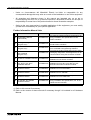
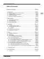
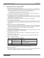
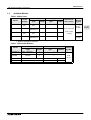
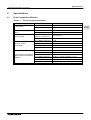
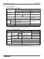
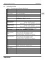
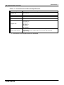
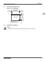
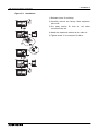
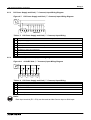
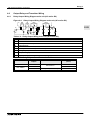
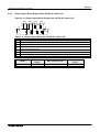
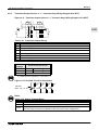
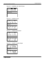
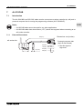
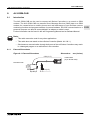
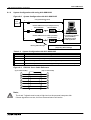
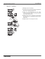
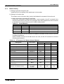
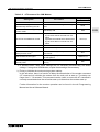
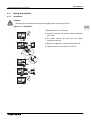
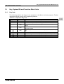
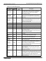
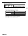
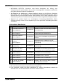
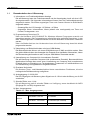
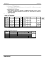
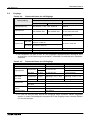
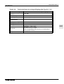
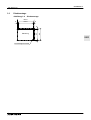
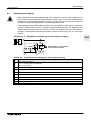
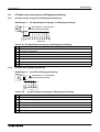
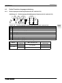
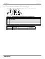
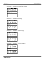
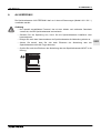
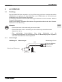
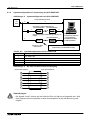
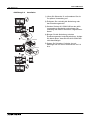
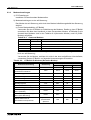
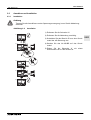
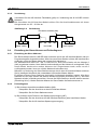
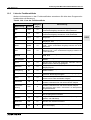
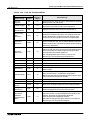
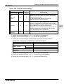
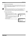
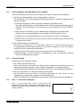
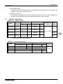
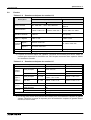
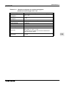
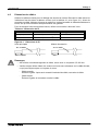
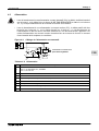
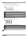
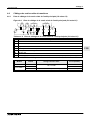
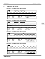
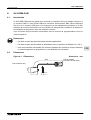
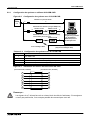
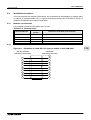
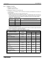
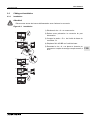
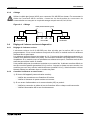
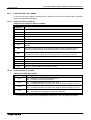
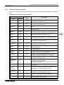
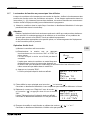
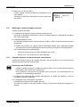
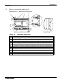
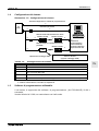
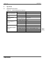
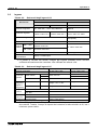
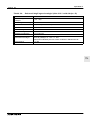
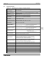
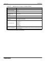
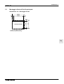
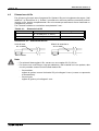
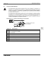
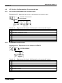
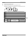
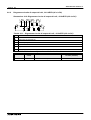
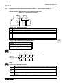
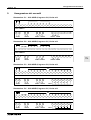
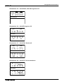
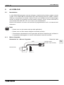
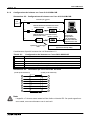
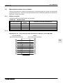
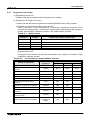
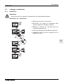
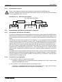
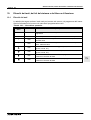
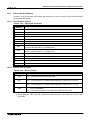
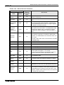
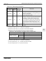
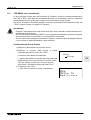
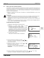
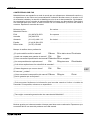
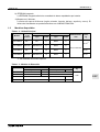
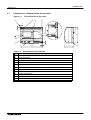
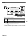
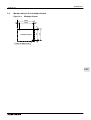
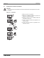
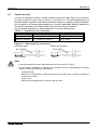
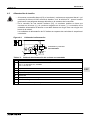
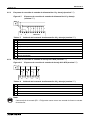
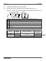
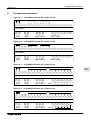
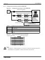
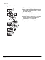
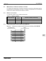
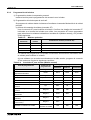
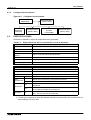
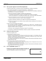
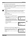
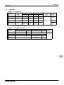
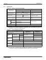
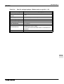
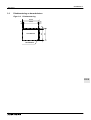
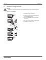
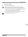
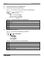
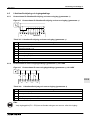
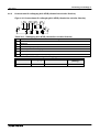
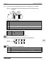
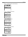
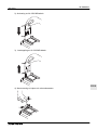
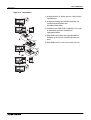
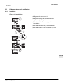
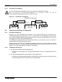
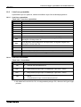
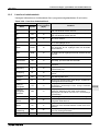
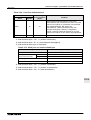
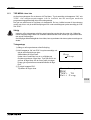
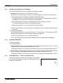
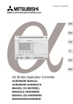
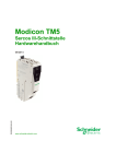
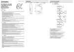
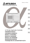
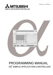
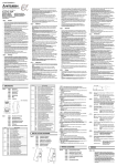
α2 Simple Application Controllers
4.5.3
Wiring 4
DC Power Supply and Sink (“-” Common) Input Wiring Diagram
Figure 4.7: DC Power Supply and Sink (”-” Common) Input Wiring Diagram
R
Q
S
V
+ - (A) (B) 1 2 3 4 5 6 7 8
T
INPUTSW
U
Table 4.7: DC Power Supply and Sink (“-” Common) Input Wiring
Ref.
4.5.4
Item Description
1
DC power supply, 24V DC
2
Circuit isolation device
3
Circuit protection device - Limit to 1.0 Amps
4
DC power terminals
5
Sink/Source input wiring terminals
6
Sensor input switches
7
Input terminals
AL2-4EX Sink (“-” Common) Input Wiring Diagram
Figure 4.8: AL2-4EX Sink (”-” Common) Input Wiring Diagram
R
Q
T
T
T
T
EI1 EI1 EI2 EI2 EI3 EI3 EI4 EI4
(+) (-) (+) (-) (+) (-) (+) (-)
S
S
S
S
Table 4.8: DC Power Supply and Sink (“-” Common) Input Wiring
Ref.
Item Description
1
DC power supply, 24V DC
2
Circuit isolation device
3
Input terminals
4
Sensor input switches
Note:
Each input terminal (EI1 ~ EI4) can be used as either Source input or Sink input.
ENG-22