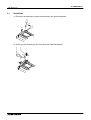
1
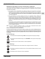
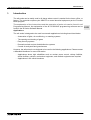
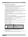
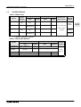
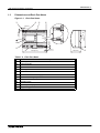
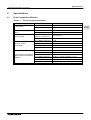
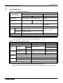
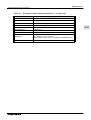
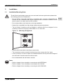
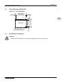
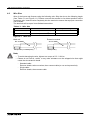
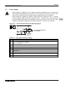
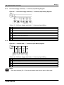
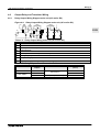
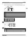
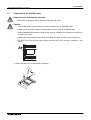
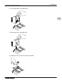
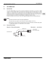
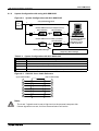
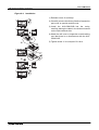
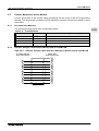
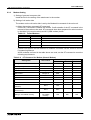
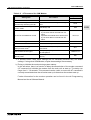
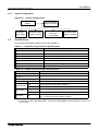
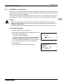
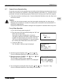
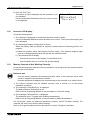
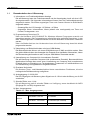
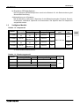
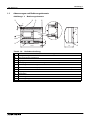
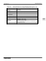
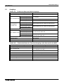
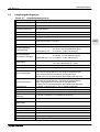
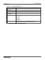
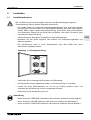
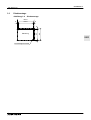
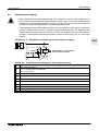
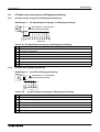
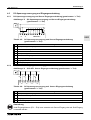
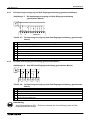
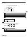
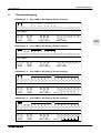
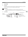
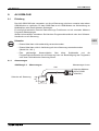
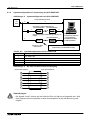
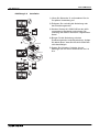
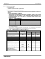
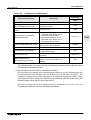
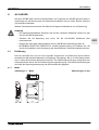
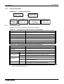
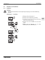
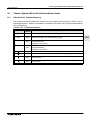
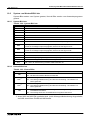
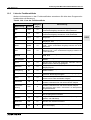
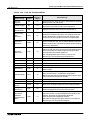
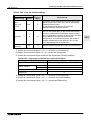
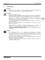
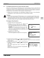
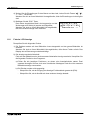
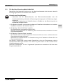
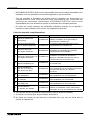
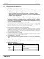
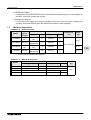
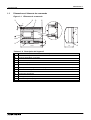
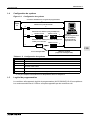
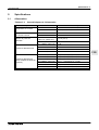
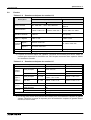
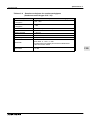
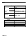
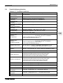
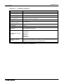
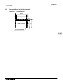
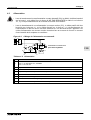
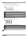
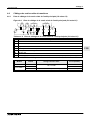
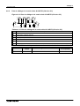
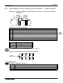
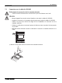
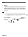
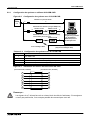
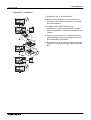
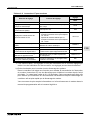
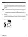
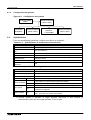
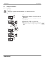
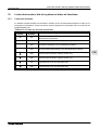
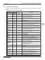
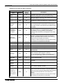
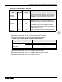
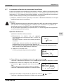
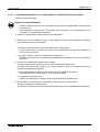
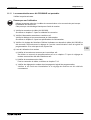
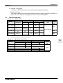
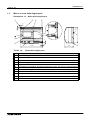
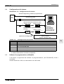
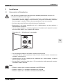
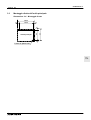
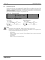
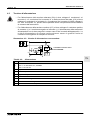
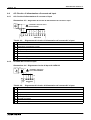
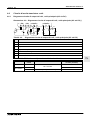
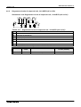
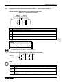
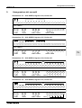
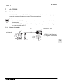
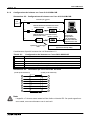
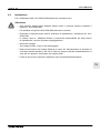
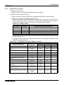
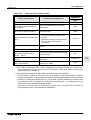
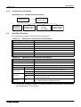
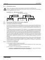
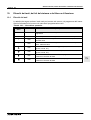
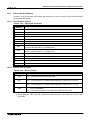
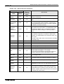
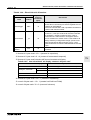
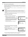
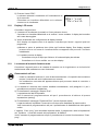
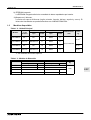
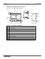
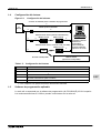
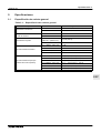
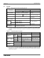
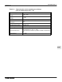
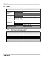
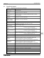
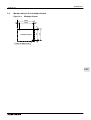
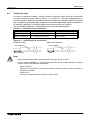
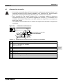
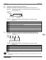
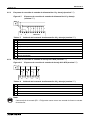
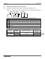
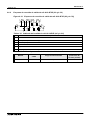
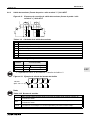
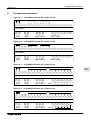
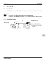
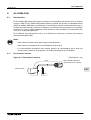
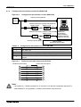
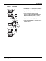
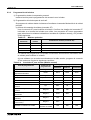
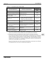
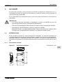
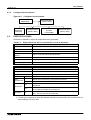
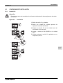
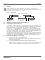
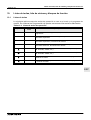
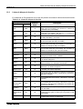
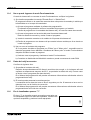
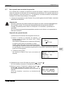
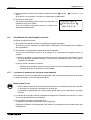
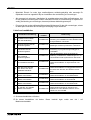
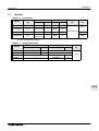
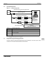
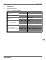
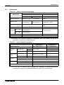
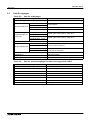
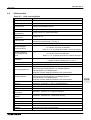
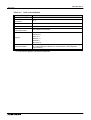
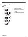
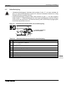
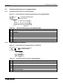
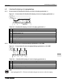
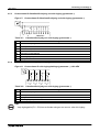
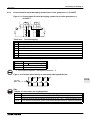
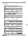
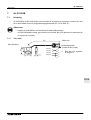
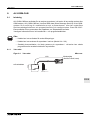
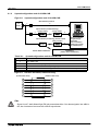
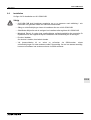
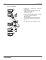
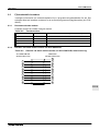
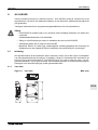
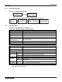
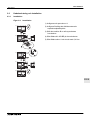
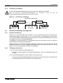
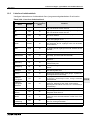
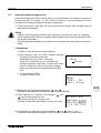
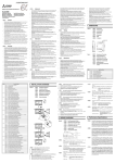
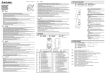
α2 Simple Application Controllers
4.6.3
Wiring 4
Transistor Output (Source or “+” Common Only) Wiring Diagram AL2-4EYT
Figure 4.11: Transistor Output (Source/ “+” Common Only) Wiring Diagram AL2-4EYT
+
-
EO1 EO2
- EO3 EO4
T
S S
S S
U U
U U
R
Q
+
T
R
ENG
V
Table 4.13: Transistor Output Wiring
Ref.
Item Description
1
DC Power Supply: 24V DC
2
Emergency Stop
3
Circuit Protection Device - See Table 4.14 for Specifications
4
Power Supply Terminal
5
Output Devices
6
DC Power Supply: 12V DC
Table 4.14: Transistor Output Circuit Protection Table
Circuit
Voltage
Circuit Protection (Fuse)
5V DC
< 0.3A/Circuit
12V DC
< 2.0A/Circuit *1
24V DC
< 2.0A/Circuit *1
*1 Power Source capacity ≥ Fuse size × 2
Figure 4.12: Example Fuse Size Calculation
12V, 8A
(8A ≥ 1A × 2 × 4)
Fuse
1A
O01
O02
Fuse
1A
O03
Fuse
1A
Fuse
1A
O04
Note;
Table 4.15: Output Terminal Notes
Volt
5
12-24
5,12,24
Output Terminal Notes
Each circuit can contain from one output terminal up to every output terminal.
Each circuit can contain from one output terminal up to every output terminal.
Using any combination of 5 Volt, 12 Volt, and 24 Volt outputs can be accomplished on the
same α2 Series Controller if separate circuits are used for each voltage level.
ENG-25