1
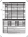
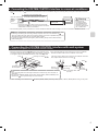
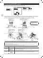
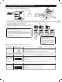
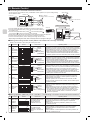
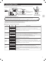
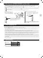
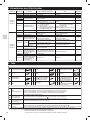
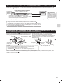
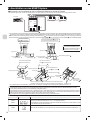
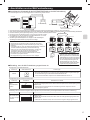
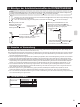
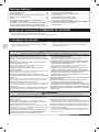
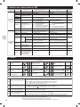
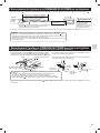
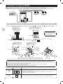
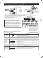
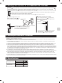
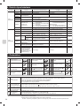
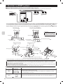
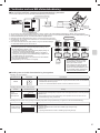
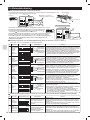
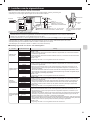
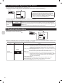
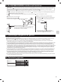
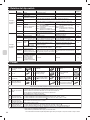
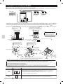
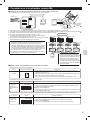
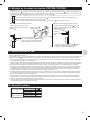
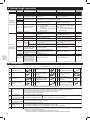
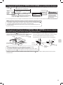
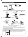
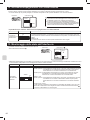
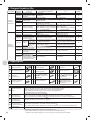
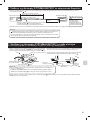
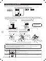
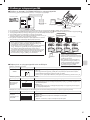
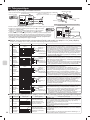
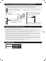
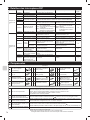
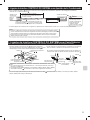
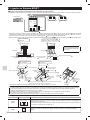
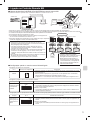
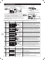
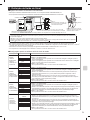
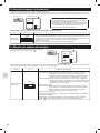
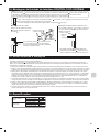
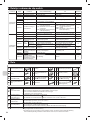
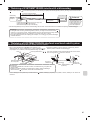
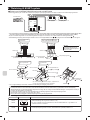
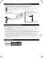
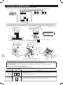
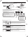
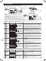
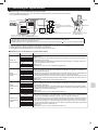
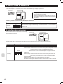
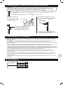
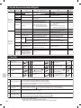
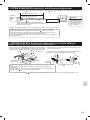
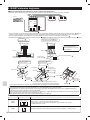
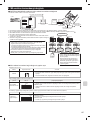
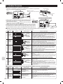
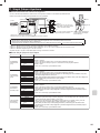
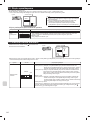
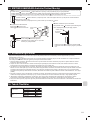
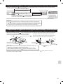
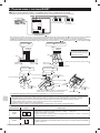
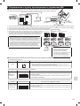
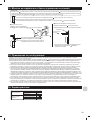
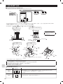
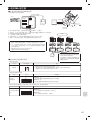
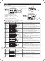
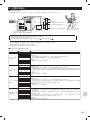
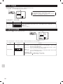
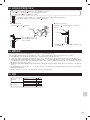
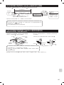
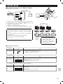
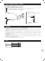
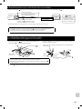
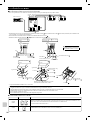
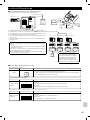
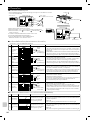
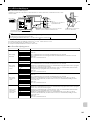
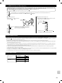
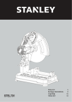
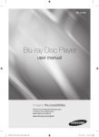
14. Mounting the SYSTEM CONTROL Interface Unit
Notes
• The Interface unit
should be placed in a location where the connecting cable (5-core) from the interface unit
can reach an indoor unit.
• The device will not function properly the connecting cable is extended, so the connecting cable (5-core) should no be extended.
• Mount the interface unit
securely to a pillar or wall using 2 or more screws .
Attach the connecting cable (5-core) of the interface unit here. Store extra connecting cable (5-core) in the ductwork space behind
the air conditioner.
If there is any slack in the connecting cable (5-core), use a fastener
to keep it in place.
■ When mounting the interface unit inside a ceiling
■ When Mounting Directly to a Wall
Mount the interface unit case to the
wall using the mounting screws .
Interface unit
screws
When mounting the interface unit inside a ceiling or
wall, install an access door to facilitate maintenance.
mounting
Interface unit
Cushioning
material .
Screw for mounting
40 mm
or more
.
When the interface unit is mounted above
an indoor unit, it should be positioned 40 mm
or more away from the unit to ensure that
ceiling grills can be removed.
* When mounting the interface unit using a cushioning
material , be sure to mount it in a location where it
will not fall.
15. Notes Regarding Use
The following control information should be thoroughly explained and provided to the users of this device. (Please provide these instructions to the
user once the installation is complete.)
This Interface unit
operates room air conditioners using the controls of a City-Multi or P series, but there are several limitations imposed as a result
of the functional differences between room air conditioners and packaged air conditioners.
1. When operating the system using a System Controller, MA Remote Controller, or ME Remote Controller these operations will not appear on the
display of the wireless remote controller.
2. When original dehumidification mode is set with the remote controller attached to the room air conditioner, “Dry” is displayed because there is no
mode corresponding to dehumidification on the MA remote controller, ME remote controller, and the system controller.
3. Because the temperature range of the room air conditioners is broader than a System Controller, MA Remote Controller, or ME Remote Controller,
when the room air conditioners is set to lower than 17°C or higher than 30°C, the temperature display on the a System Controller, MA Remote
Controller, or ME Remote Controller will show the minimum or maximum temperature that can be set. (For example, even if the room air conditioner
is set to cool a room to 16°C, the display on a System Controller, MA Remote controller, or ME Remote Controller may read “17°C”).
4. Timer operations should be set using only the remote controller that came with the room air conditioners or the a System Controller, MA Remote
Controller, or ME Remote Controller. If both are used to set the timer to the same time, the timer will not function properly.
5. When “Manual operation prohibited” (ON/OFF, setting temperature, operation mode) is set with the system controller, the corresponding operation
by the remote controller attached to the room air conditioner is not accepted, but allowed operation is reflected. A beep sounds during operation to
confirm reception.
6. A part of functions including the operation of horizontal air blow direction cannot be used from the ME remote controller, the system controller, and
the MA remote controller.
16. Specifications
Indoor unit side
Power supply unit side
Input voltage
Power consumption
Input current
Input voltage
Power consumption
Input current
12V
1.8W
0.15A
12V
4.8W
0.4A
11