1
AXP1620
Installation and Use
P/N: 6806800E23L
September 2014
©
Copyright 2014 Artesyn Embedded Technologies, Inc.
All rights reserved.
Trademarks
Artesyn Embedded Technologies, Artesyn and the Artesyn Embedded Technologies logo are trademarks and service marks of
Artesyn Embedded Technologies, Inc.© 2014 Artesyn Embedded Technologies, Inc. All other product or service names are the
property of their respective owners.
Intel® is a trademark or registered trademark of Intel Corporation or its subsidiaries in the United States and other countries.
Java™ and all other Java-based marks are trademarks or registered trademarks of Oracle America, Inc. in the U.S. and other countries.
Microsoft®, Windows® and Windows Me® are registered trademarks of Microsoft Corporation; and Windows XP™ is a trademark of
Microsoft Corporation.
PICMG®, CompactPCI®, AdvancedTCA™ and the PICMG, CompactPCI and AdvancedTCA logos are registered trademarks of the PCI
Industrial Computer Manufacturers Group.
UNIX® is a registered trademark of The Open Group in the United States and other countries.
Notice
While reasonable efforts have been made to assure the accuracy of this document, Artesyn assumes no liability resulting from any
omissions in this document, or from the use of the information obtained therein. Artesyn reserves the right to revise this document
and to make changes from time to time in the content hereof without obligation of Artesyn to notify any person of such revision or
changes.
Electronic versions of this material may be read online, downloaded for personal use, or referenced in another document as a URL to
an Artesyn website. The text itself may not be published commercially in print or electronic form, edited, translated, or otherwise
altered without the permission of Artesyn.
It is possible that this publication may contain reference to or information about Artesyn products (machines and programs),
programming, or services that are not available in your country. Such references or information must not be construed to mean that
Artesyn intends to announce such Artesyn products, programming, or services in your country.
Limited and Restricted Rights Legend
If the documentation contained herein is supplied, directly or indirectly, to the U.S. Government, the following notice shall apply
unless otherwise agreed to in writing by Artesyn.
Use, duplication, or disclosure by the Government is subject to restrictions as set forth in subparagraph (b)(3) of the Rights in
Technical Data clause at DFARS 252.227-7013 (Nov. 1995) and of the Rights in Noncommercial Computer Software and
Documentation clause at DFARS 252.227-7014 (Jun. 1995).
Contact Address
Artesyn Embedded Technologies
Artesyn Embedded Technologies
Marketing Communications
Lilienthalstr. 17-19
2900 S. Diablo Way, Suite 190
85579 Neubiberg/Munich
Tempe, Arizona 85282
Germany
Contents
About this Manual . . . . . . . . . . . . . . . . . . . . . . . . . . . . . . . . . . . . . . . . . . . . . . . . . . . . . . . . . . . . . . . . . . . . . . . 13
Safety Notes . . . . . . . . . . . . . . . . . . . . . . . . . . . . . . . . . . . . . . . . . . . . . . . . . . . . . . . . . . . . . . . . . . . . . . . . . . . . . 19
Sicherheitshinweise . . . . . . . . . . . . . . . . . . . . . . . . . . . . . . . . . . . . . . . . . . . . . . . . . . . . . . . . . . . . . . . . . . . . . . 31
1
Platform Architecture. . . . . . . . . . . . . . . . . . . . . . . . . . . . . . . . . . . . . . . . . . . . . . . . . . . . . . . . . . . . . . . . . 43
1.1
1.2
1.3
1.4
1.5
1.6
1.7
2
Description . . . . . . . . . . . . . . . . . . . . . . . . . . . . . . . . . . . . . . . . . . . . . . . . . . . . . . . . . . . . . . . . . . . . . . . . 43
PICMG Compliance . . . . . . . . . . . . . . . . . . . . . . . . . . . . . . . . . . . . . . . . . . . . . . . . . . . . . . . . . . . . . . . . . 43
Shelf Topology . . . . . . . . . . . . . . . . . . . . . . . . . . . . . . . . . . . . . . . . . . . . . . . . . . . . . . . . . . . . . . . . . . . . . 43
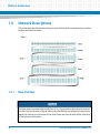
Network Descriptions . . . . . . . . . . . . . . . . . . . . . . . . . . . . . . . . . . . . . . . . . . . . . . . . . . . . . . . . . . . . . . . 44
1.4.1 Base Interface . . . . . . . . . . . . . . . . . . . . . . . . . . . . . . . . . . . . . . . . . . . . . . . . . . . . . . . . . . . . . . . 44
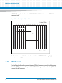
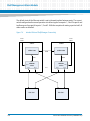
1.4.2 Fabric Interface . . . . . . . . . . . . . . . . . . . . . . . . . . . . . . . . . . . . . . . . . . . . . . . . . . . . . . . . . . . . . . 45
1.4.3 IPMI Network . . . . . . . . . . . . . . . . . . . . . . . . . . . . . . . . . . . . . . . . . . . . . . . . . . . . . . . . . . . . . . . . 46
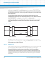
1.4.4 Update Channel Interface . . . . . . . . . . . . . . . . . . . . . . . . . . . . . . . . . . . . . . . . . . . . . . . . . . . . . 47
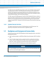
Backplane and Component Connectivity . . . . . . . . . . . . . . . . . . . . . . . . . . . . . . . . . . . . . . . . . . . . . . 47
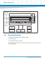
Operating Systems . . . . . . . . . . . . . . . . . . . . . . . . . . . . . . . . . . . . . . . . . . . . . . . . . . . . . . . . . . . . . . . . . 48
Remote Management and Maintenance . . . . . . . . . . . . . . . . . . . . . . . . . . . . . . . . . . . . . . . . . . . . . . . 49
AXP1620 Shelf Description . . . . . . . . . . . . . . . . . . . . . . . . . . . . . . . . . . . . . . . . . . . . . . . . . . . . . . . . . . . . 51
2.1
2.2
2.3
2.4
2.5
2.6
2.7
2.8
2.9
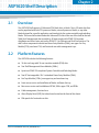
Overview . . . . . . . . . . . . . . . . . . . . . . . . . . . . . . . . . . . . . . . . . . . . . . . . . . . . . . . . . . . . . . . . . . . . . . . . . . 51
Platform Features . . . . . . . . . . . . . . . . . . . . . . . . . . . . . . . . . . . . . . . . . . . . . . . . . . . . . . . . . . . . . . . . . . 51
Enclosure . . . . . . . . . . . . . . . . . . . . . . . . . . . . . . . . . . . . . . . . . . . . . . . . . . . . . . . . . . . . . . . . . . . . . . . . . . 54
Power Consumption . . . . . . . . . . . . . . . . . . . . . . . . . . . . . . . . . . . . . . . . . . . . . . . . . . . . . . . . . . . . . . . . 54
Shelf Ground Configuration . . . . . . . . . . . . . . . . . . . . . . . . . . . . . . . . . . . . . . . . . . . . . . . . . . . . . . . . . . 54
Backplane . . . . . . . . . . . . . . . . . . . . . . . . . . . . . . . . . . . . . . . . . . . . . . . . . . . . . . . . . . . . . . . . . . . . . . . . . 55
2.6.1 Functional Layout . . . . . . . . . . . . . . . . . . . . . . . . . . . . . . . . . . . . . . . . . . . . . . . . . . . . . . . . . . . . 55
2.6.2 E-Keying . . . . . . . . . . . . . . . . . . . . . . . . . . . . . . . . . . . . . . . . . . . . . . . . . . . . . . . . . . . . . . . . . . . . 56
2.6.3 Shelf FRU Information . . . . . . . . . . . . . . . . . . . . . . . . . . . . . . . . . . . . . . . . . . . . . . . . . . . . . . . . 57
2.6.4 Backplane Slot Connectors . . . . . . . . . . . . . . . . . . . . . . . . . . . . . . . . . . . . . . . . . . . . . . . . . . . . 57
2.6.5 Zone Locations on a Blade. . . . . . . . . . . . . . . . . . . . . . . . . . . . . . . . . . . . . . . . . . . . . . . . . . . . . 60
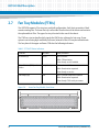
Fan Tray Modules (FTMs) . . . . . . . . . . . . . . . . . . . . . . . . . . . . . . . . . . . . . . . . . . . . . . . . . . . . . . . . . . . . 62
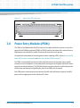
Power Entry Modules (PEMs) . . . . . . . . . . . . . . . . . . . . . . . . . . . . . . . . . . . . . . . . . . . . . . . . . . . . . . . . . 63
Stationary Boards . . . . . . . . . . . . . . . . . . . . . . . . . . . . . . . . . . . . . . . . . . . . . . . . . . . . . . . . . . . . . . . . . . . 66
AXP1620 Installation and Use (6806800E23L)
3
Contents
Contents
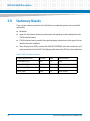
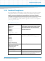
2.10 Standard Compliances . . . . . . . . . . . . . . . . . . . . . . . . . . . . . . . . . . . . . . . . . . . . . . . . . . . . . . . . . . . . . . 67
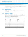
2.11 WEEE Compliance . . . . . . . . . . . . . . . . . . . . . . . . . . . . . . . . . . . . . . . . . . . . . . . . . . . . . . . . . . . . . . . . . . 69
3
Site Preparation . . . . . . . . . . . . . . . . . . . . . . . . . . . . . . . . . . . . . . . . . . . . . . . . . . . . . . . . . . . . . . . . . . . . . . 71
3.1
3.2
3.3
4
AXP1620 Operations. . . . . . . . . . . . . . . . . . . . . . . . . . . . . . . . . . . . . . . . . . . . . . . . . . . . . . . . . . . . . . . . . . 85
4.1
4.2
4.3
4.4
4.5
4.6
4.7
4.8
4
Overview . . . . . . . . . . . . . . . . . . . . . . . . . . . . . . . . . . . . . . . . . . . . . . . . . . . . . . . . . . . . . . . . . . . . . . . . . . 71
Site Planning Considerations . . . . . . . . . . . . . . . . . . . . . . . . . . . . . . . . . . . . . . . . . . . . . . . . . . . . . . . . . 71
3.2.1 Receiving and Unpacking the System . . . . . . . . . . . . . . . . . . . . . . . . . . . . . . . . . . . . . . . . . . . 71
3.2.2 Site and Installation Planning . . . . . . . . . . . . . . . . . . . . . . . . . . . . . . . . . . . . . . . . . . . . . . . . . . 73
3.2.3 Requirements . . . . . . . . . . . . . . . . . . . . . . . . . . . . . . . . . . . . . . . . . . . . . . . . . . . . . . . . . . . . . . . 73
3.2.3.1 Environmental Requirements . . . . . . . . . . . . . . . . . . . . . . . . . . . . . . . . . . . . . . . . 73
3.2.3.2 Power Requirements . . . . . . . . . . . . . . . . . . . . . . . . . . . . . . . . . . . . . . . . . . . . . . . . 76
3.2.4 Dimensions and Weight . . . . . . . . . . . . . . . . . . . . . . . . . . . . . . . . . . . . . . . . . . . . . . . . . . . . . . 77
3.2.5 Mounting Options. . . . . . . . . . . . . . . . . . . . . . . . . . . . . . . . . . . . . . . . . . . . . . . . . . . . . . . . . . . . 78
3.2.6 Airflow Requirements . . . . . . . . . . . . . . . . . . . . . . . . . . . . . . . . . . . . . . . . . . . . . . . . . . . . . . . . 79
3.2.7 Acoustic Noise Control. . . . . . . . . . . . . . . . . . . . . . . . . . . . . . . . . . . . . . . . . . . . . . . . . . . . . . . . 81
Site Planning Checklists . . . . . . . . . . . . . . . . . . . . . . . . . . . . . . . . . . . . . . . . . . . . . . . . . . . . . . . . . . . . . 82
Overview . . . . . . . . . . . . . . . . . . . . . . . . . . . . . . . . . . . . . . . . . . . . . . . . . . . . . . . . . . . . . . . . . . . . . . . . . . 85
Recommended Power-On Procedures . . . . . . . . . . . . . . . . . . . . . . . . . . . . . . . . . . . . . . . . . . . . . . . . 85
Recommended Power-Off Procedures . . . . . . . . . . . . . . . . . . . . . . . . . . . . . . . . . . . . . . . . . . . . . . . . 86
Emergency Power-Off Procedures . . . . . . . . . . . . . . . . . . . . . . . . . . . . . . . . . . . . . . . . . . . . . . . . . . . . 86
Power Entry Module (PEM) . . . . . . . . . . . . . . . . . . . . . . . . . . . . . . . . . . . . . . . . . . . . . . . . . . . . . . . . . . . 87
4.5.1 Description. . . . . . . . . . . . . . . . . . . . . . . . . . . . . . . . . . . . . . . . . . . . . . . . . . . . . . . . . . . . . . . . . . 87
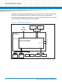
4.5.2 IPMC Circuitry . . . . . . . . . . . . . . . . . . . . . . . . . . . . . . . . . . . . . . . . . . . . . . . . . . . . . . . . . . . . . . . 88
Fan Tray Modules . . . . . . . . . . . . . . . . . . . . . . . . . . . . . . . . . . . . . . . . . . . . . . . . . . . . . . . . . . . . . . . . . . . 89
4.6.1 Description. . . . . . . . . . . . . . . . . . . . . . . . . . . . . . . . . . . . . . . . . . . . . . . . . . . . . . . . . . . . . . . . . . 89
4.6.2 Cooling Budget . . . . . . . . . . . . . . . . . . . . . . . . . . . . . . . . . . . . . . . . . . . . . . . . . . . . . . . . . . . . . . 90
4.6.3 IPMC Circuitry . . . . . . . . . . . . . . . . . . . . . . . . . . . . . . . . . . . . . . . . . . . . . . . . . . . . . . . . . . . . . . . 90
Air Filter Maintenance . . . . . . . . . . . . . . . . . . . . . . . . . . . . . . . . . . . . . . . . . . . . . . . . . . . . . . . . . . . . . . . 91
Cleaning the Air Filter . . . . . . . . . . . . . . . . . . . . . . . . . . . . . . . . . . . . . . . . . . . . . . . . . . . . . . . . . . . . . . . 91
4.8.1 Storing the Filter . . . . . . . . . . . . . . . . . . . . . . . . . . . . . . . . . . . . . . . . . . . . . . . . . . . . . . . . . . . . . 92
AXP1620 Installation and Use (6806800E23L)
Contents
5
AXP1620 Shelf Installation . . . . . . . . . . . . . . . . . . . . . . . . . . . . . . . . . . . . . . . . . . . . . . . . . . . . . . . . . . . . 93
5.1
5.2
5.3
Overview . . . . . . . . . . . . . . . . . . . . . . . . . . . . . . . . . . . . . . . . . . . . . . . . . . . . . . . . . . . . . . . . . . . . . . . . . . 93
Shelf Physical Characteristics . . . . . . . . . . . . . . . . . . . . . . . . . . . . . . . . . . . . . . . . . . . . . . . . . . . . . . . . . 93
Installation Prerequisites . . . . . . . . . . . . . . . . . . . . . . . . . . . . . . . . . . . . . . . . . . . . . . . . . . . . . . . . . . . . 94
5.3.1 Equipment You Will Need . . . . . . . . . . . . . . . . . . . . . . . . . . . . . . . . . . . . . . . . . . . . . . . . . . . . . 94
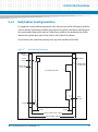
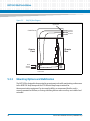
5.3.2 Rack/Cabinet Cooling Guidelines. . . . . . . . . . . . . . . . . . . . . . . . . . . . . . . . . . . . . . . . . . . . . . . 95
5.3.3 Mounting Options and Stabilization . . . . . . . . . . . . . . . . . . . . . . . . . . . . . . . . . . . . . . . . . . . . 96
5.3.4 Weight Distribution Within a Rack . . . . . . . . . . . . . . . . . . . . . . . . . . . . . . . . . . . . . . . . . . . . . 97
5.3.5 Electrostatic Discharge (ESD) and Safety Procedures . . . . . . . . . . . . . . . . . . . . . . . . . . . . . 97
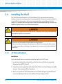
5.4 Installing the Shelf . . . . . . . . . . . . . . . . . . . . . . . . . . . . . . . . . . . . . . . . . . . . . . . . . . . . . . . . . . . . . . . . . . 98
5.4.1 23" EIA Rack/Cabinet . . . . . . . . . . . . . . . . . . . . . . . . . . . . . . . . . . . . . . . . . . . . . . . . . . . . . . . . . 98
5.4.2 600mm ETSI Rack/Cabinet . . . . . . . . . . . . . . . . . . . . . . . . . . . . . . . . . . . . . . . . . . . . . . . . . . . . 99
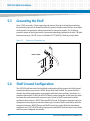
5.5 Grounding the Shelf . . . . . . . . . . . . . . . . . . . . . . . . . . . . . . . . . . . . . . . . . . . . . . . . . . . . . . . . . . . . . . . 100
5.6 Shelf Ground Configuration . . . . . . . . . . . . . . . . . . . . . . . . . . . . . . . . . . . . . . . . . . . . . . . . . . . . . . . . . 100
5.7 DC Power Cable . . . . . . . . . . . . . . . . . . . . . . . . . . . . . . . . . . . . . . . . . . . . . . . . . . . . . . . . . . . . . . . . . . . 101
5.8 Power Cable Termination . . . . . . . . . . . . . . . . . . . . . . . . . . . . . . . . . . . . . . . . . . . . . . . . . . . . . . . . . . . 103
5.9 Connecting the Cables to the PEM . . . . . . . . . . . . . . . . . . . . . . . . . . . . . . . . . . . . . . . . . . . . . . . . . . . 103
5.10 Powering Up the System . . . . . . . . . . . . . . . . . . . . . . . . . . . . . . . . . . . . . . . . . . . . . . . . . . . . . . . . . . . 105
5.11 Accessing the System . . . . . . . . . . . . . . . . . . . . . . . . . . . . . . . . . . . . . . . . . . . . . . . . . . . . . . . . . . . . . . 105
5.12 Upgrading Firmware . . . . . . . . . . . . . . . . . . . . . . . . . . . . . . . . . . . . . . . . . . . . . . . . . . . . . . . . . . . . . . . 106
5.12.1 FTM IPMC Firmware Upgrade . . . . . . . . . . . . . . . . . . . . . . . . . . . . . . . . . . . . . . . . . . . . . . . . . 106
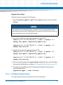
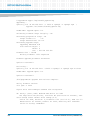
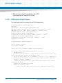
5.12.1.1 FTM Upgrade Sample Output . . . . . . . . . . . . . . . . . . . . . . . . . . . . . . . . . . . . . . . . 107
5.12.2 PEM IPMC Firmware Upgrade . . . . . . . . . . . . . . . . . . . . . . . . . . . . . . . . . . . . . . . . . . . . . . . . . 109
5.12.2.1 PEM Upgrade Sample Output . . . . . . . . . . . . . . . . . . . . . . . . . . . . . . . . . . . . . . . 110
5.12.3 Shelf Manager Firmware Upgrade . . . . . . . . . . . . . . . . . . . . . . . . . . . . . . . . . . . . . . . . . . . . . 111
5.12.3.1 Establishing Network Connectivity to the SAM . . . . . . . . . . . . . . . . . . . . . . . . . 112
5.12.3.2 Update ShM Firmware on the SAM . . . . . . . . . . . . . . . . . . . . . . . . . . . . . . . . . . . 113
6
FRU Installation . . . . . . . . . . . . . . . . . . . . . . . . . . . . . . . . . . . . . . . . . . . . . . . . . . . . . . . . . . . . . . . . . . . . . 115
6.1
6.2
Overview . . . . . . . . . . . . . . . . . . . . . . . . . . . . . . . . . . . . . . . . . . . . . . . . . . . . . . . . . . . . . . . . . . . . . . . . . 115
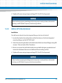
Installing RTMs, Blades and SAMs . . . . . . . . . . . . . . . . . . . . . . . . . . . . . . . . . . . . . . . . . . . . . . . . . . . . 115
6.2.1 Module Installation and Removal. . . . . . . . . . . . . . . . . . . . . . . . . . . . . . . . . . . . . . . . . . . . . . 116
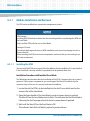
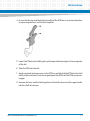
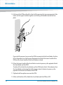
6.2.1.1 Installing the RTM . . . . . . . . . . . . . . . . . . . . . . . . . . . . . . . . . . . . . . . . . . . . . . . . . . 116
6.2.1.2 Removing the RTM . . . . . . . . . . . . . . . . . . . . . . . . . . . . . . . . . . . . . . . . . . . . . . . . . 121
AXP1620 Installation and Use (6806800E23L)
5
Contents
Contents
6.2.2
6.3
6.4
6.5
6.6
7
Shelf Management Alarm Module . . . . . . . . . . . . . . . . . . . . . . . . . . . . . . . . . . . . . . . . . . . . . . . . . . . . . 143
7.1
7.2
7.3
7.4
7.5
6
Node Blade Installation and Removal . . . . . . . . . . . . . . . . . . . . . . . . . . . . . . . . . . . . . . . . . . 123
6.2.2.1 Installing the Node Blade . . . . . . . . . . . . . . . . . . . . . . . . . . . . . . . . . . . . . . . . . . . 123
6.2.2.2 Removing the Node Blade . . . . . . . . . . . . . . . . . . . . . . . . . . . . . . . . . . . . . . . . . . 126
6.2.3 Installing and Removing the Shelf Management Alarm Module . . . . . . . . . . . . . . . . . . . 127
6.2.3.1 Non-Powered System . . . . . . . . . . . . . . . . . . . . . . . . . . . . . . . . . . . . . . . . . . . . . . 128
6.2.3.2 Powered System . . . . . . . . . . . . . . . . . . . . . . . . . . . . . . . . . . . . . . . . . . . . . . . . . . . 129
Unused Slots . . . . . . . . . . . . . . . . . . . . . . . . . . . . . . . . . . . . . . . . . . . . . . . . . . . . . . . . . . . . . . . . . . . . . . 131
Installing Power Entry Modules . . . . . . . . . . . . . . . . . . . . . . . . . . . . . . . . . . . . . . . . . . . . . . . . . . . . . . 131
6.4.1 Tools You Will Need . . . . . . . . . . . . . . . . . . . . . . . . . . . . . . . . . . . . . . . . . . . . . . . . . . . . . . . . . 132
6.4.2 Replacing the PEM . . . . . . . . . . . . . . . . . . . . . . . . . . . . . . . . . . . . . . . . . . . . . . . . . . . . . . . . . . 132
Upper and Lower Fan Tray Modules . . . . . . . . . . . . . . . . . . . . . . . . . . . . . . . . . . . . . . . . . . . . . . . . . . 135
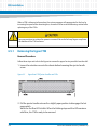
6.5.1 Removing the Upper FTM . . . . . . . . . . . . . . . . . . . . . . . . . . . . . . . . . . . . . . . . . . . . . . . . . . . . 136
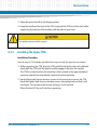
6.5.2 Installing the Upper FTM . . . . . . . . . . . . . . . . . . . . . . . . . . . . . . . . . . . . . . . . . . . . . . . . . . . . . 137
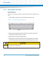
6.5.3 Removing the Lower FTM . . . . . . . . . . . . . . . . . . . . . . . . . . . . . . . . . . . . . . . . . . . . . . . . . . . . 138
6.5.4 Installing the Lower FTM . . . . . . . . . . . . . . . . . . . . . . . . . . . . . . . . . . . . . . . . . . . . . . . . . . . . . 139
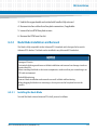
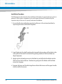
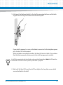
Replacing the Fan Filter . . . . . . . . . . . . . . . . . . . . . . . . . . . . . . . . . . . . . . . . . . . . . . . . . . . . . . . . . . . . 139
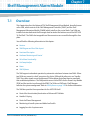
Overview . . . . . . . . . . . . . . . . . . . . . . . . . . . . . . . . . . . . . . . . . . . . . . . . . . . . . . . . . . . . . . . . . . . . . . . . . 143
Features . . . . . . . . . . . . . . . . . . . . . . . . . . . . . . . . . . . . . . . . . . . . . . . . . . . . . . . . . . . . . . . . . . . . . . . . . . 144
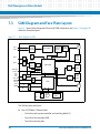
SAM Diagram and Face Plate Layout . . . . . . . . . . . . . . . . . . . . . . . . . . . . . . . . . . . . . . . . . . . . . . . . . 146
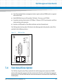
Functional Description . . . . . . . . . . . . . . . . . . . . . . . . . . . . . . . . . . . . . . . . . . . . . . . . . . . . . . . . . . . . . 147
7.4.1 IPMB Connectivity. . . . . . . . . . . . . . . . . . . . . . . . . . . . . . . . . . . . . . . . . . . . . . . . . . . . . . . . . . . 148
7.4.2 RS-232 Serial Interface . . . . . . . . . . . . . . . . . . . . . . . . . . . . . . . . . . . . . . . . . . . . . . . . . . . . . . . 148
7.4.3 Master-Only I2C Bus . . . . . . . . . . . . . . . . . . . . . . . . . . . . . . . . . . . . . . . . . . . . . . . . . . . . . . . . . 149
7.4.4 Shelf FRU SEEPROM . . . . . . . . . . . . . . . . . . . . . . . . . . . . . . . . . . . . . . . . . . . . . . . . . . . . . . . . . 149
7.4.5 SAM LEDs . . . . . . . . . . . . . . . . . . . . . . . . . . . . . . . . . . . . . . . . . . . . . . . . . . . . . . . . . . . . . . . . . . 150
7.4.5.1 Hot Swap LED . . . . . . . . . . . . . . . . . . . . . . . . . . . . . . . . . . . . . . . . . . . . . . . . . . . . . 150
7.4.5.2 SAM/ADP Status LEDs . . . . . . . . . . . . . . . . . . . . . . . . . . . . . . . . . . . . . . . . . . . . . . 151
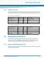
Management and Control . . . . . . . . . . . . . . . . . . . . . . . . . . . . . . . . . . . . . . . . . . . . . . . . . . . . . . . . . . 151
7.5.1 Hardware Monitoring and Control. . . . . . . . . . . . . . . . . . . . . . . . . . . . . . . . . . . . . . . . . . . . . 151
7.5.1.1 Voltage Sensors . . . . . . . . . . . . . . . . . . . . . . . . . . . . . . . . . . . . . . . . . . . . . . . . . . . 152
7.5.1.2 Temperature Monitoring . . . . . . . . . . . . . . . . . . . . . . . . . . . . . . . . . . . . . . . . . . . 152
7.5.1.3 Fan Speed and Control . . . . . . . . . . . . . . . . . . . . . . . . . . . . . . . . . . . . . . . . . . . . . . 152
7.5.2 Redundancy Control. . . . . . . . . . . . . . . . . . . . . . . . . . . . . . . . . . . . . . . . . . . . . . . . . . . . . . . . . 155
AXP1620 Installation and Use (6806800E23L)
Contents
7.6
7.7
7.8
7.9
A
7.5.2.1 Hardware Redundancy Interface . . . . . . . . . . . . . . . . . . . . . . . . . . . . . . . . . . . . . 155
7.5.2.2 HRI Protocol . . . . . . . . . . . . . . . . . . . . . . . . . . . . . . . . . . . . . . . . . . . . . . . . . . . . . . . 156
7.5.2.3 Ethernet Signals . . . . . . . . . . . . . . . . . . . . . . . . . . . . . . . . . . . . . . . . . . . . . . . . . . . 157
7.5.2.4 Configuring Front Panel Network Interface . . . . . . . . . . . . . . . . . . . . . . . . . . . . 159
7.5.2.5 Configuring RMCP Network Interface . . . . . . . . . . . . . . . . . . . . . . . . . . . . . . . . . 160
7.5.3 Switchover Signals . . . . . . . . . . . . . . . . . . . . . . . . . . . . . . . . . . . . . . . . . . . . . . . . . . . . . . . . . . 160
Telco Alarm Functionality . . . . . . . . . . . . . . . . . . . . . . . . . . . . . . . . . . . . . . . . . . . . . . . . . . . . . . . . . . . 161
7.6.1 Telco Alarm Cutoff Push Button . . . . . . . . . . . . . . . . . . . . . . . . . . . . . . . . . . . . . . . . . . . . . . . 161
7.6.2 Telco Alarm LEDs. . . . . . . . . . . . . . . . . . . . . . . . . . . . . . . . . . . . . . . . . . . . . . . . . . . . . . . . . . . . 161
7.6.3 Telco Alarm Interface . . . . . . . . . . . . . . . . . . . . . . . . . . . . . . . . . . . . . . . . . . . . . . . . . . . . . . . . 162
Hot Swap Interface . . . . . . . . . . . . . . . . . . . . . . . . . . . . . . . . . . . . . . . . . . . . . . . . . . . . . . . . . . . . . . . . 163
Power . . . . . . . . . . . . . . . . . . . . . . . . . . . . . . . . . . . . . . . . . . . . . . . . . . . . . . . . . . . . . . . . . . . . . . . . . . . . 163
SAM Software . . . . . . . . . . . . . . . . . . . . . . . . . . . . . . . . . . . . . . . . . . . . . . . . . . . . . . . . . . . . . . . . . . . . . 163
7.9.1 imls Utility . . . . . . . . . . . . . . . . . . . . . . . . . . . . . . . . . . . . . . . . . . . . . . . . . . . . . . . . . . . . . . . . . 163
Related Documentation . . . . . . . . . . . . . . . . . . . . . . . . . . . . . . . . . . . . . . . . . . . . . . . . . . . . . . . . . . . . . . 167
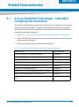
A.1
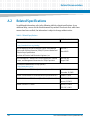
A.2
Artesyn Embedded Technologies - Embedded Computing Documentation . . . . . . . . . . . . . . . 167
Related Specifications . . . . . . . . . . . . . . . . . . . . . . . . . . . . . . . . . . . . . . . . . . . . . . . . . . . . . . . . . . . . . . 168
AXP1620 Installation and Use (6806800E23L)
7
Contents
Contents
8
AXP1620 Installation and Use (6806800E23L)
List of Figures
Figure 1-1
Figure 1-2
Figure 2-1
Figure 2-2
Figure 2-3
Figure 2-4
Figure 2-5
Figure 2-6
Figure 2-7
Figure 2-8
Figure 2-9
Figure 2-10
Figure 3-1
Figure 3-2
Figure 3-3
Figure 3-4
Figure 5-1
Figure 5-2
Figure 5-3
Figure 5-4
Figure 6-1
Figure 6-2
Figure 6-3
Figure 6-4
Figure 7-1
Figure 7-2
Figure 7-3
Figure 7-4
Fabric Option 1, 2, and 3 . . . . . . . . . . . . . . . . . . . . . . . . . . . . . . . . . . . . . . . . . . . . . . . . . 46
Location of Zones 1, 2, and 3 . . . . . . . . . . . . . . . . . . . . . . . . . . . . . . . . . . . . . . . . . . . . . 48
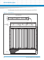
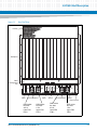
Front Shelf View . . . . . . . . . . . . . . . . . . . . . . . . . . . . . . . . . . . . . . . . . . . . . . . . . . . . . . . . 52
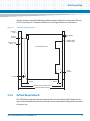
Rear Shelf View . . . . . . . . . . . . . . . . . . . . . . . . . . . . . . . . . . . . . . . . . . . . . . . . . . . . . . . . . 53
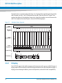
Backplane Power Segments . . . . . . . . . . . . . . . . . . . . . . . . . . . . . . . . . . . . . . . . . . . . . . 56
Blade Slot Connectivity . . . . . . . . . . . . . . . . . . . . . . . . . . . . . . . . . . . . . . . . . . . . . . . . . . 61
Hub Slot Connectivity . . . . . . . . . . . . . . . . . . . . . . . . . . . . . . . . . . . . . . . . . . . . . . . . . . . 61
Lower Fan Tray Module, Front View . . . . . . . . . . . . . . . . . . . . . . . . . . . . . . . . . . . . . . . . 62
Upper Front FTM, Front View . . . . . . . . . . . . . . . . . . . . . . . . . . . . . . . . . . . . . . . . . . . . . 63
PEM Backplane Connectivity . . . . . . . . . . . . . . . . . . . . . . . . . . . . . . . . . . . . . . . . . . . . . 64
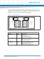
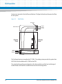
PEM View with Detail . . . . . . . . . . . . . . . . . . . . . . . . . . . . . . . . . . . . . . . . . . . . . . . . . . . . 65
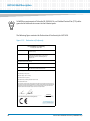
Declaration of Conformity . . . . . . . . . . . . . . . . . . . . . . . . . . . . . . . . . . . . . . . . . . . . . . . . 68
Rack Mounting Dimensions . . . . . . . . . . . . . . . . . . . . . . . . . . . . . . . . . . . . . . . . . . . . . . 79
Shelf Airflow . . . . . . . . . . . . . . . . . . . . . . . . . . . . . . . . . . . . . . . . . . . . . . . . . . . . . . . . . . . . 80
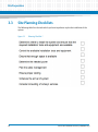
Planning Checklist 1 . . . . . . . . . . . . . . . . . . . . . . . . . . . . . . . . . . . . . . . . . . . . . . . . . . . . . 82
Planning Checklist 2 . . . . . . . . . . . . . . . . . . . . . . . . . . . . . . . . . . . . . . . . . . . . . . . . . . . . . 83
Rack Mounting Dimensions . . . . . . . . . . . . . . . . . . . . . . . . . . . . . . . . . . . . . . . . . . . . . . 95
Shelf Airflow Diagram . . . . . . . . . . . . . . . . . . . . . . . . . . . . . . . . . . . . . . . . . . . . . . . . . . . 96
Placement of Grounding Lug . . . . . . . . . . . . . . . . . . . . . . . . . . . . . . . . . . . . . . . . . . . . 100
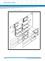
DC Power Connection Detail . . . . . . . . . . . . . . . . . . . . . . . . . . . . . . . . . . . . . . . . . . . . . 102
SAM-1500R . . . . . . . . . . . . . . . . . . . . . . . . . . . . . . . . . . . . . . . . . . . . . . . . . . . . . . . . . . . 128
Upper Rear FTM Ejector Handles and LEDs . . . . . . . . . . . . . . . . . . . . . . . . . . . . . . . . . 136
Lower Front FTM Ejector Handles and LEDs . . . . . . . . . . . . . . . . . . . . . . . . . . . . . . . . 138
Position of the Fan Filter . . . . . . . . . . . . . . . . . . . . . . . . . . . . . . . . . . . . . . . . . . . . . . . . . 141
Block Diagram of SAM . . . . . . . . . . . . . . . . . . . . . . . . . . . . . . . . . . . . . . . . . . . . . . . . . . 146
SAM Face Plate . . . . . . . . . . . . . . . . . . . . . . . . . . . . . . . . . . . . . . . . . . . . . . . . . . . . . . . . . 147
SAM HRI Interconnection . . . . . . . . . . . . . . . . . . . . . . . . . . . . . . . . . . . . . . . . . . . . . . . 156
Interhub Slot and Shelf Manager Connectivity . . . . . . . . . . . . . . . . . . . . . . . . . . . . . 158
AXP1620 Installation and Use (6806800E23L)
9
List of Figures
10
AXP1620 Installation and Use (6806800E23L)
List of Tables
Table 2-1
Table 2-2
Table 2-3
Table 2-4
Table 2-5
Table 2-6
Table 2-7
Table 2-8
Table 2-9
Table 2-10
Table 3-1
Table 3-2
Table 3-3
Table 3-4
Table 4-1
Table 4-2
Table 5-1
Table 7-1
Table 7-2
Table 7-3
Table 7-4
Table 7-5
Table 7-6
Table 7-7
Table 7-8
Table 7-9
Table 7-10
Table A-1
Table A-2
AXP1620 Shelf Power Requirements . . . . . . . . . . . . . . . . . . . . . . . . . . . . . . . . . . . . . . . . . . . . . . 54
Slot Connector Description . . . . . . . . . . . . . . . . . . . . . . . . . . . . . . . . . . . . . . . . . . . . . . . . . . . . . . 57
Backplane Connectors . . . . . . . . . . . . . . . . . . . . . . . . . . . . . . . . . . . . . . . . . . . . . . . . . . . . . . . . . . 58
Slot Hardware Addressing for J10 . . . . . . . . . . . . . . . . . . . . . . . . . . . . . . . . . . . . . . . . . . . . . . . . 58
Fan Tray Module Hardware Addressing . . . . . . . . . . . . . . . . . . . . . . . . . . . . . . . . . . . . . . . . . . . . 59
SAM and PEM Hardware Addressing . . . . . . . . . . . . . . . . . . . . . . . . . . . . . . . . . . . . . . . . . . . . . . 60
FTM LED Status Indicators . . . . . . . . . . . . . . . . . . . . . . . . . . . . . . . . . . . . . . . . . . . . . . . . . . . . . . . 62
PEM LED Status Indicators . . . . . . . . . . . . . . . . . . . . . . . . . . . . . . . . . . . . . . . . . . . . . . . . . . . . . . . 65
ADP LED Status Indicators . . . . . . . . . . . . . . . . . . . . . . . . . . . . . . . . . . . . . . . . . . . . . . . . . . . . . . . 66
Standard Compliances . . . . . . . . . . . . . . . . . . . . . . . . . . . . . . . . . . . . . . . . . . . . . . . . . . . . . . . . . . 67
Environmental Conditions . . . . . . . . . . . . . . . . . . . . . . . . . . . . . . . . . . . . . . . . . . . . . . . . . . . . . . . 74
Critical Temperature Limits . . . . . . . . . . . . . . . . . . . . . . . . . . . . . . . . . . . . . . . . . . . . . . . . . . . . . . 75
System Power Requirements . . . . . . . . . . . . . . . . . . . . . . . . . . . . . . . . . . . . . . . . . . . . . . . . . . . . 77
Dimensions and Weight of System and Components . . . . . . . . . . . . . . . . . . . . . . . . . . . . . . . 77
PEM IPMB Addresses . . . . . . . . . . . . . . . . . . . . . . . . . . . . . . . . . . . . . . . . . . . . . . . . . . . . . . . . . . . 88
Cooling Budget . . . . . . . . . . . . . . . . . . . . . . . . . . . . . . . . . . . . . . . . . . . . . . . . . . . . . . . . . . . . . . . . 90
AXP1620 16-Slot Shelf Physical Characteristics . . . . . . . . . . . . . . . . . . . . . . . . . . . . . . . . . . . . 93
RJ-45 Serial Port Connector . . . . . . . . . . . . . . . . . . . . . . . . . . . . . . . . . . . . . . . . . . . . . . . . . . . . 148
Alarm Display Panel (ADP) Serial Port Connector . . . . . . . . . . . . . . . . . . . . . . . . . . . . . . . . . . 149
SAM LEDs . . . . . . . . . . . . . . . . . . . . . . . . . . . . . . . . . . . . . . . . . . . . . . . . . . . . . . . . . . . . . . . . . . . . 150
Hot Swap LED States . . . . . . . . . . . . . . . . . . . . . . . . . . . . . . . . . . . . . . . . . . . . . . . . . . . . . . . . . . 150
SAM LED Status Indicators . . . . . . . . . . . . . . . . . . . . . . . . . . . . . . . . . . . . . . . . . . . . . . . . . . . . . . 151
ADP LED Status Indicators . . . . . . . . . . . . . . . . . . . . . . . . . . . . . . . . . . . . . . . . . . . . . . . . . . . . . . 151
Cooling Budget . . . . . . . . . . . . . . . . . . . . . . . . . . . . . . . . . . . . . . . . . . . . . . . . . . . . . . . . . . . . . . . 154
Shelf Manager Static Network IP Interfaces . . . . . . . . . . . . . . . . . . . . . . . . . . . . . . . . . . . . . . . 159
Shelf Manager Dynamic Network IP Interfaces . . . . . . . . . . . . . . . . . . . . . . . . . . . . . . . . . . . . 159
Hot Swap Interface Pin Out . . . . . . . . . . . . . . . . . . . . . . . . . . . . . . . . . . . . . . . . . . . . . . . . . . . . . 162
Artesyn Embedded Technologies - Embedded Computing Publications . . . . . . . . . . . . . . 167
Related Specifications . . . . . . . . . . . . . . . . . . . . . . . . . . . . . . . . . . . . . . . . . . . . . . . . . . . . . . . . . 168
AXP1620 Installation and Use (6806800E23L)
11
List of Tables
12
AXP1620 Installation and Use (6806800E23L)
About this Manual
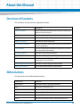
Overview of Contents
This Installation and Use manual is organized as follows:
Chapter
Description
About this Manual
Lists all conventions and abbreviations used in this manual and
outlines the revision history
Safety Notes
Describes the safety information which has to be regarded
Sicherheitshinweise
Translation of the chapter "Safety Notes" to German
Platform Architecture
Describes the system architecture
AXP1620 Shelf Description
Provides an overview of the features of the system and lists the
standard compliances
Site Preparation
Provides site planning considerations and checklists, describes
the requirements and conditions
AXP1620 Operations
Describes basic operating procedures
AXP1620 Shelf Installation
Describes mounting and installation options
FRU Installation
Describes how to install and replace blades, modules, power
components, fans, and air filter
Shelf Management Alarm Module
Describes the shelf management alarm module
Related Documentation
Lists related documentation and specifications
Abbreviations
This document uses the following abbreviations:
Abbreviation
Definition
AdvancedTCA
Advanced Telecom Computing Architecture
AMC
AdvancedTCA Mezzanine Card
ANSI
American National Standards Institute
ARP
Address Resolution Protocol
ARTM
AdvancedTCA Rear Transition Module
ATCA
Advanced Telecommunications Computing Architecture
AXP1620 Installation and Use (6806800E23L)
13
About this Manual
14
About this Manual
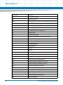
Abbreviation
Definition
AWG
American Wire Gauge
BBS
Basic Blade Services
CISPR
Comité International Spécial des Perturbations Radioélectriques
CO
Central Office
EMC
Electromagnetic Compatibility
EMI
Electromagnetic Interference
EMV
Elektromagnetische Vertraeglichkeit
EN
European Norm
ESD
Electrostatic Discharge
ETSI
European Telecommunication Standards Institute
FAE
Field Application Engineer
FCC
Federal Communications Commission
FRU
Field Replaceable Unit
HA
High Availability
HS
Hot Swap
ID
Identifier
IEC
International Electric Code
IEEE
Institute of Electrical and Electronics Engineers
IPM
Intelligent Platform Management
IPMB
Intelligent Platform Management Bus
IPMC
Intelligent Platform Management Controller
IPMI
Intelligent Platform Management Interface
MMC
Mezzanine Management Controller
NEBS
Network Equipment Building System
NEC
National Electric Code
OEM
Original Equipment Manufacturer
PCI
Peripheral Component Interconnect
PEM
Power Entry Module
AXP1620 Installation and Use (6806800E23L)
About this Manual
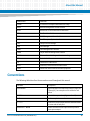
Abbreviation
Definition
PICMG
PCI Industrial Computer Manufacturers Group
RMCP
Remote Management Control Protocol
RoHS
Restriction of Certain Hazardous Substances
RTM
Rear Transition Module
SAM
Shelf Management Alarm Module
SCSI
Small Computer System Interface
SELV
Safety Extra Low Voltage
ShM
Shelf Manager
ShMC
Shelf Management Controller
SNMP
Simple Network Management Protocol
TNV-2
Telecom Network Voltages without overvoltage
TPE
Twisted-Pair Ethernet
UL
Underwriters Laboratories
VCCI
Voluntary Control Council for Interference
WEEE
Waste from Electrical and Electronic Equipment
Conventions
The following table describes the conventions used throughout this manual.
Notation
Description
0x00000000
Typical notation for hexadecimal numbers (digits are
0 through F), for example used for addresses and
offsets
0b0000
Same for binary numbers (digits are 0 and 1)
bold
Used to emphasize a word
Screen
Used for on-screen output and code related elements
or commands in body text
Courier + Bold
Used to characterize user input and to separate it
from system output
AXP1620 Installation and Use (6806800E23L)
15
About this Manual
About this Manual
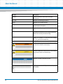
Notation
Description
Reference
Used for references and for table and figure
descriptions
File > Exit
Notation for selecting a submenu
<text>
Notation for variables and keys
[text]
Notation for software buttons to click on the screen
and parameter description
...
Repeated item for example node 1, node 2, ..., node
12
.
Omission of information from example/command
that is not necessary at the time being
.
.
..
Ranges, for example: 0..4 means one of the integers
0,1, 2, 3, and 4 (used in registers)
|
Logical OR
Indicates a hazardous situation which, if not avoided,
could result in death or serious injury
Indicates a hazardous situation which, if not avoided,
may result in minor or moderate injury
Indicates a property damage message
No danger encountered. Pay attention to important
information
16
AXP1620 Installation and Use (6806800E23L)
About this Manual
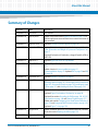
Summary of Changes
Order No.
Date
Description
6806800E23A
June 2008
First Release
6806800E23B
January 2009
Added a step in the section Replacing the PEM on page 132; to
add the input power terminal block cover removal instruction to
the procedure.
6806800E23C
February 2010
Updated FTM IPMC Firmware Upgrade on page 106
6806800E23D
November 2010
Updated Table "Hot Swap Interface Pin Out" on page 162 and
Table "Dimensions and Weight of System and Components" on
page 77
Updated Declaration of Conformity: changed Centellis 4620 to
AXP1620.
6806800E23E
March 2011
Updated Upper and Lower Fan Tray Modules
6806800E23F
March 2012
Updated Figure 7-1. Updated section Ethernet Signals on page
157.
Added a Notice in System Installation on page 21
Systeminstallation on page 33. Updated EMC on page 20 and EMV
on page 32.
6806800E23G
December 2012
Updated Standard Compliances on page 67.
6806800E23H
May 2013
Updated Receiving and Unpacking the System on page 71,
Mounting Options on page 78, Connecting the Cables to the PEM on
page 103, Accessing the System on page 105, Installing the Upper
FTM on page 137, and Installing the Lower FTM on page 139.
6806800E23J
May 2014
Re-branded to Artesyn template.
Updated Figure "Declaration of Conformity" on page 68.
Updated the sections Grounding the Shelf on page 100, RS-232
Serial Interface on page 148 and Ethernet Signals on page 157.
Added new sections Configuring Front Panel Network Interface on
page 159 and Configuring RMCP Network Interface on page 160.
Updated Figure 7-4 on page 158.
6806800E23K
August 2014
Added Installation procedure and modified Removal procedure
under the section Replacing the PEM on page 132.
6806800E23L
September 2014
Updated the section Grounding the Shelf on page 100.
AXP1620 Installation and Use (6806800E23L)
17
About this Manual
18
About this Manual
AXP1620 Installation and Use (6806800E23L)
Safety Notes
This section provides warnings that precede potentially dangerous procedures throughout
this manual. Instructions contained in the warnings must be followed during all phases of
operation, service, and repair of this equipment. You should also employ all other safety
precautions necessary for the operation of the equipment in your operating environment.
Failure to comply with these precautions or with specific warnings elsewhere in this manual
could result in personal injury or damage to the equipment.
Artesyn intends to provide all necessary information to install and handle the product in this
manual. Because of the complexity of this product and its various uses, we do not guarantee
that the given information is complete. If you need additional information, ask your Artesyn
representative.
The product has been designed to meet the standard industrial safety requirements. It must
only be used in its specific area of office telecommunication industry, industrial control, and
development. It must not be used in safety critical components, life supporting devices or on
aircraft.
Only personnel trained by Artesyn or persons qualified in electronics or electrical engineering
are authorized to install, remove or maintain the product. The information given in this manual
is meant to complete the knowledge of a specialist and must not be used as replacement for
qualified personnel.
Keep away from live circuits inside the equipment. Operating personnel must not remove
equipment covers. Only factory authorized service personnel or other qualified service
personnel may remove equipment covers for internal subassembly or component replacement
or any internal adjustment.
Do not install substitute parts or perform any unauthorized modification of the equipment or
the warranty may be voided. Contact your local Artesyn representative for service and repair
to make sure that all safety features are maintained.
General
Danger of Injuries
At the system's rear there are sharp pins which can cause injuries.
Be careful when handling the system.
AXP1620 Installation and Use (6806800E23L)
19
Safety Notes
EMC
The product has been tested and found to comply with the limits for a Class A digital device in
this system, pursuant to part 15 of the FCC Rules, EN 55022 Class A respectively. These limits
are designed to provide reasonable protection against harmful interference when the product
is operated in a commercial, business or industrial environment.
The product generates and uses radio frequency energy and, if not installed properly and used
in accordance with this user's documentation, may cause harmful interference to radio
communications. Operating the product in a residential area is likely to cause harmful
interference, in which case the user will be required to correct the interference at his own
expense.
To ensure EMC protection use only shielded cables when connecting peripherals to assure that
appropriate radio frequency emissions compliance is maintained. Installed blades must have
the face plates installed and all vacant slots in the shelf must be covered.
An AXP1620 that is shipped as a spare, replacement chassis, or an unconfigured system will not
have filler panels installed. It is the responsibility of the customer to ensure that all open slots
are filled with payload blades, rear transition modules (RTMs), or approved filler panels in order
to be compliant with the safety/EMC regulatory markings.
Grounding
To ensure the system is properly grounded, each of the system's parts must contact the EMI
gasket. The system contains gaskets at the shelf and module level.
The shelf is also fitted with ESD contacts. Please take care for proper ESD protection of the
operator.
This is a Class A product based on the standard of the Voluntary Control Council for
Interference by Information Technology Interference (VCCI). If this equipment is used in a
domestic environment, radio disturbance may arise. When such trouble occurs, the user may
be required to take corrective actions.
The equipment is suitable for installation in a Common Bonding Network (CBN) or Isolated
Bonding Network (IBN).
20
AXP1620 Installation and Use (6806800E23L)
Safety Notes
System Installation
System Damage
To avoid system damage verify that the system environment meets the environmental and
power requirements given in this manual before installing the system.
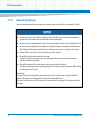
Before you begin to set up and cable your new system, consider these guidelines:
Restricted access area: Install the system only in a restricted access area.
Installation codes: This unit must be installed in accordance with the National Electrical
Code, Articles 110.16, 110.17, and 110.18 and the Canadian Electrical Code, Section 12.a
Overcurrent protection: A readily accessible listed branch circuit overcurrent protective
device must be incorporated into the building wiring. For appropriate AWG rating of the
overcurrent protection device see NEC Table 310.16 and other national regulations.
The protective bonding conductor depends on your power distribution topology. Make
sure that you use an appropriate protective bonding conductor regarding the rating of the
branch circuit protection.
Install the system safely. Make sure that cables and cords are out of the way.
Make sure that the set-up is comfortable for users.
System Damage
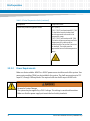
WARNING: The intra-building port(s) of the equipment or subassembly is suitable for
connection to intra-building or unexposed wiring or cabling only. The intra-building port(s) of
the equipment or subassembly MUST NOT be metallically connected to interfaces that
connect to the OSP or its wiring. These interfaces are designed for use as intra-building
interfaces only (Type 2 or Type 4 ports as described in GR-1089) and require isolation from the
exposed OSP cabling. The addition of Primary Protectors is not sufficient protection in order to
connect these interfaces metallically to OSP wiring.
System Damage
Environmental contamination can impair system operation.
Locate the system in a stable area free of excess movement and jarring and free of dust, smoke,
and electrostatic discharge (ESD). Make sure that the temperature does not exceed the
operating temperature given in the environmental requirements in this manual and allow
room for proper air flow for cooling.
AXP1620 Installation and Use (6806800E23L)
21
Safety Notes
Personal Injury or System Damage
The system is supplied by a TNV2 voltage. This voltage is considered hazardous.
Make sure that the power supply meets the local safety standards.
System Overheating
Inproper cooling leads to blade damage.
To ensure proper cooling always operate the system in a horizontal position. Furthermore,
keep clear at least 6 cm adjacent to the cooling vents on the chassis front and back side. For
detailed information refer to Site Planning Considerations on page 71.
Personal or System Damage
Unstable system installation in a rack can cause the rack to topple over.
Therefore, if your system is the only one in the rack, make sure to mount the system in the
lowest part of the rack. If other systems are installed in one rack, start with the heaviest
component at the bottom.
If the rack is equipped with stabilizing devices, make sure that they are installed and extended
so that the rack is secure. Then proceed to mount or service the system.
Personal Injury or System Damage
When pulling the system out of the rack, it can fall down and cause injuries.
Pull out the system cautiously.
Personal Injury or System Damage
The system is heavy and if you carry it on your own you can hurt your back.
To prevent injury, keep your back straight and have two people lift the system or use additional
lifting equipment.
System Damage
During the course of handling, shipping, and assembly, pins, shrouds and mounting screws,
fans and other items can become loose or damaged.
Do not operate a damaged shelf, this can cause damage to devices that interface with it.
22
AXP1620 Installation and Use (6806800E23L)
Safety Notes
Electrical Hazard
The caution label on the system's rear near the grounding studs shows that you have to create
an earth connection because there may be a high leakage current which is considered as
hazardous.
High leakage current can cause injuries. Therefore, it is essential that you create an earth
connection before connecting the PEM to a telecommuncation network.
System Damage
Wrong jumper settings can make the shelf in-operable. Therefore, never change the settings
of the jumpers.
Blade and RTM Installation
Damage of Circuits
Electrostatic discharge and incorrect RTM or blade installation and removal can damage
circuits or shorten their life.
Before touching the RTM, blade or electronic components, make sure that you are working in
an ESD-safe environment.
Installation Sequence of RTMs and AdvancedTCA Blades
If you are going to install an RTM and an AdvancedTCA blade you have to regard the following
sequence:
First install the RTM, then install the matching AdvancedTCA blade. Otherwise the blades and
RTMs will be damaged.
Blade or System Damage
Installing a blade in the wrong slot causes blade or system damage.
Only install blades in the designated slots.
AXP1620 Installation and Use (6806800E23L)
23
Safety Notes
Damage of RTM and Front Blade
Removing the RTM from the system while the playload of the front blade is powered up may
damage the front blade and RTM.
Whenever removing the RTM from the system, you have to power down the playload of the
front blade first.
RTM Malfunctioning
Incorrect RTM installation and removal can result in RTM malfunctioning.
When plugging the RTM in or removing it, do not press on the face plate but use the handles.
RTM Damage
Installing the RTM with other blades than the ones designed for it may damage the RTM and
the front blade.
Only install the RTM with the correct front blade.
Data Loss
Removing the RTM with the system power on and the blue LED on the front blade still flashing
causes data loss.
Before removing the RTM from a powered system, power down the slot by opening the lower
handle of the front blade and wait until the blue LED is permanently ON.
Blade Malfunctioning
Incorrect blade installation and removal can result in blade malfunctioning.
Make sure that the blade is connected to the system backplane through all assembled
connectors and that power is available on all zone 1 power pins.
Operation
System Overheating
Cooling vents
Inproper cooling can lead to blade and system damage.
24
AXP1620 Installation and Use (6806800E23L)
Safety Notes
To ensure proper cooling and undisturbed airflow through the system always operate the
system in a horizontal position and keep clear at least 60 mm at the back of the system. Do not
obstruct the ventilation openings at the top and back of the system. Keep the fresh air intake
at the bottom front side of the chassis completely clear, and ensure that fresh air supply is not
mixed with hot exhaust from other devices.
To ensure proper air flow within the system make sure that all slots are populated with either
filler blades, blades or dummy blades.
Product Damage
High humidity and condensation on blade surfaces causes short circuits.
Do not operate the system outside the specified environmental limits. Make sure the system is
completely dry and there is no moisture on any surface before applying power. Do not start the
system below 0ºC.
Injury
Caution: this unit has four -48V to -60V DC feeds. All must be disconnected to de-energize the
system. To reduce the risk of injury, disconnect the feeds when removing power from the
system.
System Damage
Air Filter
Air contamination can pollute the air filter and obstruct the air intake of the system which may
cause system overheating and component damage.
To guarantee proper airflow through the system, the air filter has to be replaced at least every
six months. Artesyn Embedded Technologies recommends to replace the air filter every 90
days. Filter replacement frequency depends on the environment the system is subjected to.
Because central offices vary in physical location and cleanliness, check your air filters every
week after you first install your system. In a dusty environment, a filter may need cleaning
more often than a filter in a cleaner environment. Check the filters frequently until you have a
good idea of how often it needs cleaning. Based on your findings, establish a regular cleaning
schedule and keep a log to record the date of each filter cleaning or replacement.
AXP1620 Installation and Use (6806800E23L)
25
Safety Notes
This equipment is designed to permit the connection of the earthed conductor of the DC
supply circuit to the earthing conductor at the equipment. If this connection is made, all of the
following conditions must be met:
This equipment shall be connected directly to the DC supply system earthing electrode
conductor or to a bonding jumper from an earthing terminal bar or bus to which the DC
supply system earthing electrode conductor is connected.
This equipment shall be located in the same immediate area (such as, adjacent cabinets)
as any other equipment that has a connection between the earthed conductor of the same
DC supply circuit and the earthing conductor, and also the point of earthing of the DC
system. The DC system shall not be earthed elsewhere.
The DC supply source shall be located within the same premises as this equipment.
Switching or disconnecting devices shall not be in the earthed circuit conductor between
the DC source and the point of connection of the earthing electrode conductor.
French translation: Cet appareil est conçu pour permettre le raccordement du conducteur relié
à la terre du circuit d'alimentation c.c. au conducteur de terre de l'appareil. Pour ce
raccordement, toutes les conditions suivantes doivent être respectées:
Ce matériel doit être raccordé directement au conducteur de la prise de terre du circuit
d'alimentation c.c. ou à une tresse de mise à la masse reliée à une barre omnibus de terre
laquelle est raccordée à l'électrode de terre du circuit d'alimentation c.c.
Les appareils dont les conducteurs de terre respectifs sont raccordés au conducteur de
terre du même circuit d'alimentation c.c. doivent être installés à proximité les uns des
autres (p.ex., dans des armoires adjacentes) et à proximité de la prise de terre du circuit
d'alimentation c.c. Le circuit d'alimentation c.c. ne doit comporter aucune autre prise de
terre.
La source d'alimentation du circuit c.c. doit être située dans la même pièce que le matériel.
- Il ne doit y avoir aucun dispositif de commutation ou de sectionnement entre le point de
raccordement au conducteur de la source d'alimentation c.c. et le point de raccordement
à la prise de terre.
System Overheating
If you reduce the fan speed, the system temperature will rise.
Constantly control the system temperature once you have reduced the fan speed.
While operating the system ensure that the environmental and power requirements are met.
26
AXP1620 Installation and Use (6806800E23L)
Safety Notes
Injuries or Short Circuits
Blade or Power Supply
In case the ORing diodes of the blade fail, the blade may trigger a short circuit between input
line A and input line B so that line A remains powered even if it is disconnected from the power
supply circuit (and vice versa).
To avoid damage or injuries, always check that there is no more voltage on the line that has
been disconnected before continuing your work.
Expansion
System Overload
To avoid an overload of the system check the total power consumption of all components
installed (see the technical specification of the respective components). Ensure that any
individual output current of any source stays within its acceptable limits (see the technical
specification of the respective source).
Loss of Safety Compliance
Using of Additional Plug-in Blades
By using additional plug-in blades it may be possible that the system may be no more
compliant to safety and EMC regulations.
The system integrator has to ensure that the compliancy is guaranteed.
Exchanging PEMs
Personal Injury through Electric Shock and Burning
Touching the PEM power input terminals with metallic objects on your hands, wrists, or
hanging from your neck may lead to serious injuries like burns or amputations. Do not wear any
metallic attire or commodity on your hands, wrists, or hanging from your neck when working
at the power input terminals or power input cables. Be extremely careful when you use
electrically conductive tools near the PEMs.
Short Circuits or Personal Injury
Ensure that the power feeds you plan to remove or attach are powered off and cannot be
switched on while you are working.
AXP1620 Installation and Use (6806800E23L)
27
Safety Notes
Short Circuit and Electric Shock
To avoid short circuits and electric shock, the power lugs must not be energized before
removing the screws. It is essential to ensure that the power lugs are not energized before
loosening the screws. Be careful with the used tools in order to prevent a short circuit.
PEM Damage
Applying reversal power causes damage to the electrolytic capacitors of the filter. Therefore,
only switch on the breakers if no red light is visible.
Exchanging Fans
Personal Injury
Rotating Fans
Inserting tools or fingers into operational fans may cause injuries.
Fans become exposed when the fan tray is pulled. Keep clear of the fans as long as they are
rotating.
When the fan is removed, extreme care should be taken while handling the fan itself. The
centrifugal forces will make the unit difficult to handle.
Cabling
Personal Injury
The cabling should follow existing cable paths using existing or similar cable fastenings.
Never change the system's cabling as delivered by Artesyn. Check proper function of the
system after cabling extensions. To avoid injuries always ensure that cables are securely
installed so that nobody can trip over them.
Personal Injury through Electric Shock
Touching contacts and cables during system operation can cause injuries through electric
shock.
To avoid electric shock make sure that contacts and cables of the system cannot be touched
while the system is operating. If in doubt concerning cabling, ask your local Artesyn
representative.
28
AXP1620 Installation and Use (6806800E23L)
Safety Notes
Cable Damage
Folding the fiber cable damages the cable and inhibits the data transmission. Therefore, make
sure you do not fold the cable.
RJ-45 Connector
System Damage
RJ-45 connectors on blades are either twisted-pair Ethernet (TPE) or E1/T1/J1 network
interfaces. Connecting an E1/T1/J1 line to an Ethernet connector may damage your system.
Make sure that TPE connectors near your working area are clearly marked as network
connectors.
Verify that the length of an electric cable connected to a TPE bushing does not exceed 100
m.
Make sure the TPE bushing of the system is connected only to safety extra low voltage
circuits (SELV circuits).
If in doubt, ask your system administrator.
Laser
Personal Injury
Some variants of the blades in the system are Class 1 laser products. The use of controls or
adjustments or performance of procedures other than those specified herein may result in
hazardous radiation exposure.
Some variants of the RTM are a Class 1 laser product. The use of controls or adjustments or
performance of procedures other than those specified herein may result in hazardous radiation
exposure.
Battery
Blade Damage
Wrong battery installation may result in hazardous explosion and blade damage.
AXP1620 Installation and Use (6806800E23L)
29
Safety Notes
Always use the same type of battery as is installed and make sure the battery is installed as
described in the user manual of the blade.
Always dispose of old batteries according to your country's legislation.
Environment
Environmental
Always dispose of used blades, system components and RTMs according to your country’s
legislation and manufacturer’s instructions.
30
AXP1620 Installation and Use (6806800E23L)
Sicherheitshinweise
Dieses Kapitel enthält Hinweise, die potentiell gefährlichen Prozeduren innerhalb dieses
Handbuchs vorrangestellt sind. Beachten Sie unbedingt in allen Phasen des Betriebs, der
Wartung und der Reparatur des Systems die Anweisungen, die diesen Hinweisen enthalten
sind. Sie sollten außerdem alle anderen Vorsichtsmaßnahmen treffen, die für den Betrieb des
Systems innerhalb Ihrer Betriebsumgebung notwendig sind. Wenn Sie diese
Vorsichtsmaßnahmen oder Sicherheitshinweise, die an anderer Stelle diese Handbuchs
enthalten sind, nicht beachten, kann das Verletzungen oder Schäden am System zur Folge
haben.
Artesyn ist darauf bedacht, alle notwendigen Informationen zum Einbau und zum Umgang mit
dem System in diesem Handbuch bereit zu stellen. Da es sich jedoch bei dem System um ein
komplexes Produkt mit vielfältigen Einsatzmöglichkeiten handelt, können wir die
Vollständigkeit der im Handbuch enthaltenen Informationen nicht garantieren. Falls Sie
weitere Informationen benötigen sollten, wenden Sie sich bitte an die für Sie zuständige
Geschäftsstelle von Artesyn.
Das System erfüllt die für die Industrie geforderten Sicherheitsvorschriften und darf
ausschließlich für Anwendungen in der Telekommunikationsindustrie, im Zusammenhang mit
Industriesteuerungen und in der Entwicklung verwendet werden. Es darf nicht in
sicherheitskritischen Anwendungen, lebenserhaltenden Geräten oder in Flugzeugen
verwendet werden.
Einbau, Wartung und Betrieb dürfen nur von durch Artesyn Embedded Technologies
ausgebildetem oder im Bereich Elektronik oder Elektrotechnik qualifiziertem Personal
durchgeführt werden. Die in diesem Handbuch enthaltenen Informationen dienen
ausschließlich dazu, das Wissen von Fachpersonal zu ergänzen, können dieses jedoch nicht
ersetzen.
Halten Sie sich von stromführenden Leitungen innerhalb des Systems fern. Entfernen Sie auf
keinen Fall die Systemabdeckung. Nur werksseitig zugelassenes Wartungspersonal oder
anderweitig qualifiziertes Wartungspersonal darf die Systemabdeckung entfernen, um
Systemkomponenten zu ersetzen oder andere Anpassungen vorzunehmen.
Installieren Sie keine Ersatzteile oder führen Sie keine unerlaubten Veränderungen am System
durch, sonst verfällt die Garantie. Wenden Sie sich für Wartung oder Reparatur bitte an die für
Sie zuständige Geschäftsstelle von Artesyn Embedded Technologies. So stellen Sie sicher, dass
alle sicherheitsrelevanten Aspekte beachtet werden.
AXP1620 Installation and Use (6806800E23L)
31
Sicherheitshinweise
Allgemein
Verletzungsgefahr
An der Rückseite des Systems befinden sich spitze Stifte, an denen Sie sich verletzen können.
Seien Sie vorsichtig im Umgang mit dem System.
EMV
Das Produkt wurde getestet und erfüllt die für digitale Geräte der Klasse A gültigen Grenzwerte
gemäß den FCC-Richtlinien Abschnitt 15 bzw. EN 55022 Klasse A. Diese Grenzwerte sollen
einen angemessenen Schutz vor Störstrahlung beim Betrieb des Produkts in Geschäfts-,
Gewerbe- sowie Industriebereichen gewährleisten.
Das Produkt arbeitet im Hochfrequenzbereich und erzeugt Störstrahlung. Bei
unsachgemäßem Einbau und anderem als in diesem Handbuch beschriebenen Betrieb können
Störungen im Hochfrequenzbereich auftreten.
Benutzen Sie zum Anschließen von Peripheriegeräten ausschließlich abgeschirmte Kabel. So
stellen Sie sicher, dass ausreichend Schutz vor Störstrahlung vorhanden ist. Die Blades müssen
mit der Frontblende installiert und alle freien Steckplätze müssen mit Blindblenden abgedeckt
sein.
Ein AXP1620, das als Ersatzteil, Austauschchassis oder unkonfiguriertes System ausgeliefert
wird, enthält keine Platzhalter-Boards. Es liegt in der Kundenverantwortung sicherzustellen,
dass alle leeren Steckplätze mit Boards, RTMs oder zugelassenen Platzhalter-Boards belegt
sind, um die Sicherheits- und EMC-Vorschriften zu erfüllen.
Erdung
Um eine korrekte Erdung des Systems zu gewährleisten, befinden sich sowohl am System als
auch an den einzelnen Modulen Dichtungen. Stellen Sie sicher, dass alle Systemteile die EMI
Dichtung berühren.
Am System befinden sich auch ESD Kontakte. Stellen Sie sicher, dass jede Person, die mit dem
System arbeitet, mit ESD-Schutz, zum Beispiel ESD Bändern, ausgerüstet ist.
32
AXP1620 Installation and Use (6806800E23L)
Sicherheitshinweise
Das Produkt ist eine Einrichtung der Klasse A gemäß dem Standard des Voluntary Control
Council for Interference von Information Technology Interference (VCCI). Wird das Produkt in
Wohngegenden betrieben, können Störungen im Hochfrequenzbereich auftreten. In einem
solchen Fall ist der Benutzer verpflichtet, entsprechende Gegenmaßnahmen zu ergreifen.
Das Produkt ist für den Einsatz in Netzwerken mit gemeinsamem Potentialausgleich oder mit
isoliertem Potentialausgleich geeignet.
Systeminstallation
Beschädigung des Systems
Bevor Sie das System installieren, überprüfen Sie, ob die im Handbuch beschriebenen
Anforderungen erfüllt werden.
Beachten Sie folgende allgemeinen Sicherheitshinweise vor der Installation und Verkabelung
des Systems:
Bereich mit eingeschränktem Zugang - Installieren Sie das System nur in Bereichen mit
eingeschränktem Zugang.
Installationsrichtlinien: Dieses System muss gemäß folgender Richtlinien installiert
werden: National Electrical Code, Artikel 110.16, 110.17 und 110.18 und Canadian
Electrical Code, Abschnitt 12.a
Überstrom Schutzeinrichtung - Eine leicht zugängliche Trennvorrichtung muss in der
Gebäudeverkabelung eingebaut sein. Einen angemessenen AWG (American Wire Gauge amerikanische Norm für Drahtquerschnitte) Wert der Überstrom Schutzeinrichtung
können Sie der NEC (National Electrical Code) Tabelle 310.16 oder anderen nationalen
Regelwerken entnehmen.
Der Erdungsleiter ist abhängig von der Spannungsverteilungstopologie innerhalb Ihrer
Anlage. Stellen Sie sicher, dass Sie einen angemessenen Erdungsleiter gemäß der
Auslegung des Zugangsleitungsschutzes verwenden.
Bauen Sie das System sicher ein. Stellen Sie sicher, dass Kabel und Leitungen nicht im Weg
sind.
Stellen Sie sicher, dass der Systemaufbau anwenderfreundlich ist.
AXP1620 Installation and Use (6806800E23L)
33
Sicherheitshinweise
Beschädigung des Systems
Die Gebäude-internen Schnittstellen ("intra-building ports" per GR-1089-CORE) der Geräte
oder Baugruppen sind nur für gebäudeinterne Verkabelung vorgesehen. Die Schnittstellen
sind als Typ 2 oder Typ 4 definiert (wie in GR-1089-Core beschrieben) und erfordern eine
Isolation zu Leitungen außerhalb des Gebäudes.
Die Gebäude-internen Schnittstellen dürfen keine elektrisch leitende Verbindung zu Leitungen
außerhalb des Gebäudes haben. Ein "Primary Protector" (wie in GR-1089-CORE beschrieben)
ist keine ausreichende Absicherung, um die Gebäude-internen Schnittstellen mit Leitungen
außerhalb des Gebäudes zu verbinden.
Beschädigung des Systems
Verschmutzungen können das System beschädigen.
Betreiben Sie das System an einem erschütterungsfreien Ort, an dem weder Staub, Rauch noch
elektrostatische Entladungen auftreten. Stellen Sie außerdem sicher, dass die klimatischen
Bedingungen, die in diesem Handbuch spezifiziert sind, eingehalten werden und genug Raum
für die Luftzirkulation vorhanden ist.
Verletzungsgefahr und Beschädigung des Systems
Das System ist an eine TNV-2 Spannungsquelle angeschlossen. Diese Spannung kann
gefährlich sein.
Stellen Sie sicher, dass die externe Spannungsversorgung den entsprechenden
Sicherheitsstandards entspricht.
System Überhitzung
Unzureichende Kühlung kann zu einer Beschädigung der Boards führen.
Um eine ausreichende Kühlung sicherzustellen betreiben Sie das System nur aufrecht. Sorgen
Sie außerdem dafür, dass ein aureichender Mindestabstand (mindestens 6 cm) vor den
Lüftungsschlitzen an der Vorder- und Rückseite des Systems freigehalten wird. Genaue
Informationen finden Sie im Kapitel Site Planning Considerations on page 71.
34
AXP1620 Installation and Use (6806800E23L)
Sicherheitshinweise
Verletzungsgefahr und Beschädigung des Systems
Wenn die Gewichte im Schaltschrank ungleich verteilt sind, kann der Schaltschrank umkippen.
Bauen Sie das System deshalb ganz unten im Schrank ein, wenn es das einzige System im
Schrank ist. Wenn mehrere Systeme in einen Schrank eingebaut werden sollen, plazieren Sie
das schwerste System ganz unten und die leichteren weiter oben. Falls der Schaltschrank mit
Kippsicherungen ausgestattet ist, stellen Sie sicher, dass diese auch installiert und ausgefahren
sind, um einen sicheren Stand des Schranks zu gewährleisten. Beginnen Sie erst danach mit
dem Einbau oder der Wartung des Systems.
Verletzungsgefahr oder Beschädigung des Systems
Das System kann beim Herausziehen herunterfallen und Verletzungen verursachen.
Ziehen Sie das System vorsichtig heraus, damit es nicht herunterfällt.
Verletzungsgefahr oder Beschädigung des Systems
Das System ist schwer, und wenn Sie es alleine tragen, kann dies zu Rückenschäden führen.
Heben Sie deshalb das System nur zu zweit und halten Sie beim Heben Ihren Rücken gerade
oder benutzen Sie zusätzliche Hilfsmittel.
Beschädigung des Systems
Während des Transportes und Zusammenbaus des Systems können sich Teile, wie zum
Beispiel Schrauben, Blenden, Stecker oder Lüfter lösen oder beschädigt werden.
Nehmen Sie das System nicht in Betrieb, wenn Teile beschädigt sind. Dies könnte zu
Beschädigungen an anderen Teilen führen.
Hoher Ableitstrom
Dieser Aufkleber befindet sich in der Nähe der Schuzleiter auf der Rückseite des Systems und
warnt, dass Sie vor der Inbetriebnahme eine Erdung durchführen müssen, da hier ein hoher
Ableitstrom vorhanden sein kann.
AXP1620 Installation and Use (6806800E23L)
35
Sicherheitshinweise
Hoher Ableitstrom kann zu Verletzungen führen.
Stellen Sie deshalb vor Anschluss des Systems an ein Telekommunikationsnetz unbedingt eine
Erdungsverbindung her.
Beschädigung des Systems
Falsche Jumper-Einstellungen können dazu führen, dass das System nicht mehr funktioniert.
Ändern Sie deshalb nie die Einstellungen der Jumper.
Board und RTM Installation
Beschädigung des Boards
Berühren Sie das Board oder elektrische Komponenten in einem nicht ESD-geschützten
Bereich, kann dies zu einer Beschädigung des Boards führen.
Bevor Sie Boards oder elektronische Komponenten berühren, vergewissern Sie sich, dass Sie in
einem ESD-geschützten Bereich arbeiten.
Reihenfolge bei der Installation von RTMs und AdvancedTCA Boards
Die folgende Reihenfolge muß bei der Installation von RTMs und AdvancedTCA Boards
eingehalten werden:
Installieren Sie zuerst das RTM und erst danach das passende AdvancedTCA Board. Ansonsten
können RTM oder Board beschädigt werden.
Beschädigung des Boards oder Systems
Wird ein Board in den falschen Steckplatz im System gesteckt, können sowohl das Board als
auch das System beschädigt werden. Installieren Sie Boards deshalb ausschließlich in dafür
vorgesehene Steckplätze.
Beschädigung des RTMs oder Boards
Wird das RTM ausgebaut, während die Payload des dazugehörigen AdvancedTCA Boards noch
nicht heruntergefahren ist, kann dies zu Beschädigungen am Board oder RTM führen.
Fahren Sie deshalb die Payload des AdvancedTCA Blades immer herunter, bevor Sie das
dazugehörige RTM aus dem System entfernen.
36
AXP1620 Installation and Use (6806800E23L)
Sicherheitshinweise
Beschädigung des RTMs
Fehlerhafte Installation kann zu einer Beschädigung des RTMs führen. Verwenden Sie die
Handles, um das RTM zu installieren/deinstallieren. Auf diese Weise vermeiden Sie, dass die
Frontblende oder die Platine deformiert oder zerstört werden.
Beschädigung des RTMs oder Boards
Das System wird beschädigt, wenn die RTMs nicht zu den von vorne in dem System
installierten Boards passen.
Stellen Sie deshalb sicher, dass Boards und RTMs, die von vorne bzw. von hinten in den gleichen
Steckplatz des Systems eingebaut werden, stets zueinander passen.
Datenverlust
Das Entfernen eines RTMs während des Systembetriebs und blinkender blauer LED des Front
Boards führt zu Datenverlust.
Vor dem Entfernen des RTMs im laufenden Systembetrieb, schalten Sie das entsprechende
Board ab, indem Sie die Griffe des Boards öffnen. Warten Sie, bis die blaue LED dauerhaft
leuchtet.
Fehlfunktion
Unsachgemäßer Ein- und Ausbau von Boards kann zu einer Fehlfunktion des Boards führen.
Vergewissern Sie sich, dass das Board über alle Stecker an die AdvancedTCA-Backplane
angeschlossen und die Stromversorgung gewährleistet ist.
Betrieb
Überhitzung des Systems
Lüftungsschlitze
Unzureichende Lüftung kann Schäden an Boards und am System verursachen.
AXP1620 Installation and Use (6806800E23L)
37
Sicherheitshinweise
Um eine ausreichende Lüftung zu gewährleisten, stellen Sie sicher, dass das System während
des Betriebs stets waagerecht steht und dass ein Freiraum von mindestens 60 mm an der
Rückseite des Systems vorhanden ist. Halten Sie die Lüftungsschlitze an der Oberseite und der
Rückseite des Systems frei. Halten Sie die Frischluftzufuhröffnung an der unteren Vorderseite
des Systems völlig frei und stellen Sie sicher, dass sich die Frischluft nicht mit der Abluft von
anderen Systemen mischt.
Um eine ungestörte Luftzirkulation zu gewährleisten, stellen Sie sicher, dass alle Steckplätze
mit Boards oder Platzhaltern belegt sind.
Beschädigung des Systems
Durch hohe Luftfeuchtigkeit können Kurzschlüsse entstehen.
Betreiben Sie das System nur innerhalb der angegebenen Grenzwerte für die relative
Luftfeuchtigkeit und Temperatur. Stellen Sie vor dem Einschalten des Stroms sicher, dass sich
auf dem System und auf den Boards kein Kondensat befindet und starten Sie das System nicht
unter 0ºC.
Stromschlaggefahr
Das System besitzt vier -48V bis -60V DC Anschlüsse. Alle Anschlüsse müssen vom System
entfernt werden, um das System spannungsfrei zu schalten.
Um eine Verletzungsgefahr zu minimieren, entfernen Sie die Anschlüsse, wenn Sie das System
ausschalten.
Beschädigung des Systems
Luftfilter
Verunreinigungen in der Luft können den Luftfilter verschmutzen und so die Luftzufuhr des
Systems beeinträchtigen. Das kann zur Überhitzung des Systems und zu Schäden an
Systemteilen führen.
Um einen reibungslosen Luftstrom durch das System zu gewährleisten, sollten Sie den
Luftfilter spätestens alle sechs Monate austauschen. Artesyn empfiehlt, die Lüfter alle 90 Tage
auszutauschen. Wie häufig Sie die Filter austauschen müssen, hängt von der Umgebung ab, in
der das System betrieben wird. Da die Verhältnisse in Vermittlungsstellen sehr unterschiedlich
sein können, sollten Sie die Luftfilter nach der Erstinstallation des Systems jede Woche
kontrollieren. In einer staubigen Umgebung muss ein Filter gegebenenfalls öfter gereinigt
38
AXP1620 Installation and Use (6806800E23L)
Sicherheitshinweise
werden als in einer sauberen Umgebung. Prüfen Sie den Filter regelmäßig bis Sie eine
Vorstellung davon haben, wie oft der Filter gereinigt werden muss. Erstellen Sie aufgrund Ihrer
Beobachtungen einen Reinigungsplan und protokollieren Sie jede Reinigung oder jeden
Austausch des Filters.
Überhitzung des Systems
Wenn Sie die Geschwindigkeit der Lüfter reduzieren, steigt die Systemtemperatur an.
Kontrollieren Sie deshalb ständig die Temperatur im System, wenn Sie die Geschwindigkeit der
Lüfter reduziert haben. Stellen Sie während des Betriebs sicher, dass die Bedingungen, die im
Handbuch beschrieben sind, eingehalten werden.
Verletzungen oder Kurzschlüsse
Blade oder Stromversorgung
Falls die ORing Dioden des Blades durchbrennen, kann das Blade einen Kurzschluss zwischen
den Eingangsleitungen A und B verursachen. In diesem Fall ist Leitung A immer noch unter
Spannung, auch wenn sie vom Versorgungskreislauf getrennt ist (und umgekehrt).
Prüfen Sie deshalb immer, ob die Leitung spannungsfrei ist, bevor Sie Ihre Arbeit fortsetzen,
um Schäden oder Verletzungen zu vermeiden.
Ausbau/Erweiterung
Systemüberlastung
Verhindern Sie eine Systemüberlastung, indem Sie die gesamte aufgenomme Leistung aller
eingebauten Komponenten, also z.B. der installierten Blades und Laufwerke (siehe die
technischen Daten der entsprechenden Komponente) überprüfen. Stellen Sie sicher, dass der
Ausgangsstrom jedes Verbrauchers innerhalb der zulässigen Grenzwerte liegt.
Verlust der Sicherheitszulassung
Verwendung zusätzlicher Module
Wenn Sie zusätzliche Module und Boards verwenden, ist es möglich, dass das System nicht
mehr den gültigen Sicherheits- und EMV Normen entspricht. Der Systemintegrator muss die
Einhaltung der gültigen Normen sicherstellen.
AXP1620 Installation and Use (6806800E23L)
39
Sicherheitshinweise
Austausch von PEMs
Verletzungsgefahr durch Stromschlag und Verbrennungen
Berühren metallische Gegenstände an Händen, Handgelenken oder am Hals die Input
Terminals der PEMs, kann dies zu extremen Verletzungen, wie zum Beispiel Verbrennungen
oder Amputationen führen. Tragen Sie bei der Arbeit mit dem System keine metallischen
Gegenstände an Ihren Händen oder Armen und lassen sie keine metallischen Gegenstände um
Ihren Hals hängen. Seien Sie extrem vorsichtig mit elektrisch leitenden Gegenständen in der
Nähe der PEMs.
Kurzschluß und Gefahr durch Stromschlag
Um einen elektrischen Schlag zu vermeiden, überzeugen Sie sich, dass vor dem Austausch des
PEMs die Stromzufuhr unterbrochen ist und während des Austausches unterbrochen bleibt.
Kurzschluß und Gefahr durch Stromschlag
Um Kurzschlüsse und elektrischen Schlag zu vermeiden, überzeugen Sie sich, dass vor dem
Lösen der Schrauben die Stromzufuhr unterbrochen ist und während des Austausches
unterbrochen bleibt. Vermeiden Sie Kurzschlüsse, indem Sie sehr vorsichtig mit dem
Werkzeug umgehen.
Beschädigung der Spannungsversorgungseinheit
Wir die Spannungsversorgungseinheit verkehrt angeschlossen, werden die
Elektrolytkondensatoren der Filter beschädigt. Schalten Sie die Unterbrecher deshalb nur,
wenn das rote Licht nicht sichtbar ist.
Lüfteraustausch
Verletzungsgefahr
Rotierende Lüfterschaufeln
Sie können verletzt werden, wenn Sie Werkzeuge oder Finger in laufende Lüfter einführen.
Wenn Sie die Lüfterschublade aus dem Chassis ziehen, wird die Abdeckung der Lüfterschaufeln
freigelegt. Berühren Sie die Lüfterschaufeln nicht.
Seien Sie vorsichtig nach dem Herausziehen des Lüfters, da die Zentrifugalkräfte noch wirken
und somit die Handhabung erschweren können.
40
AXP1620 Installation and Use (6806800E23L)
Sicherheitshinweise
Verkabelung/Kabelführung
Verletzungsgefahr
Verändern Sie nie die von Artesyn ausgelieferte Verkabelung des Systems.
Stellen Sie sicher, dass die Verkabelung schon existierenden Kabelführungen folgt und
bestehende oder ähnliche Befestigungen verwendet. Überprüfen Sie nach der Erweiterung der
Verkabelung, ob das System ordnungsgemäß arbeitet.
Reduzieren Sie die Verletzungsgefahr, indem Sie Kabel so verlegen, dass niemand darüber
stolpern kann.
Verletzungsgefahr durch Stromschlag
Durch das Berühren von Kontakten und Kabeln während des Betriebs können Sie einen
elektrischen Schlag bekommen.
Schließen Sie in jedem Fall aus, dass Personen durch einen elektrischen Schlag verletzt werden
können, indem Sie sicherstellen, dass Kontakte und Kabel des Systems während des Betriebs
nicht berührt werden können.
Falls Sie Fragen bezüglich der Verkabelung haben, wenden Sie sich an die für Sie zuständige
Geschäftsstelle von Artesyn.
Beschädigung der Kabel
Werden Kabel geknickt, kann das Kabel beschädigt werden und der Datentransfer nicht mehr
stattfinden. Stellen Sie sicher, dass Kabel nicht geknickt werden.
RJ-45 Stecker
Beschädigung des Systems
Bei den RJ-45 Steckern, die sich auf den Boards befinden, handelt es sich entweder um TwistedPair-Ethernet (TPE) oder um E1/T1/J1-Stecker. Beachten Sie, dass ein versehentliches
Anschließen einer E1/T1/J1 Leitung an einen TPE-Stecker Ihr System zerstören kann.
Kennzeichnen Sie deshalb TPE-Anschlüsse in der Nähe Ihres Arbeitsplatzes deutlich als
Netzwerkanschlüsse.
Stellen Sie sicher, dass die Länge eines mit Ihrem Systems verbundenen TPE-Kabels 100 m
nicht überschreitet.
AXP1620 Installation and Use (6806800E23L)
41
Sicherheitshinweise
Das System darf über die TPE Stecker nur mit einem Sicherheits-KleinspannungsStromkreis (SELV) verbunden werden.
Bei Fragen wenden Sie sich an Ihren Systemverwalter.
Laser
Verletzungsgefahr
Einige Boards, die in verschiedenen Systemkonfigurationen verwendet werden, sind
Laserprodukte der Klasse 1. Verwenden Sie diese anders als in der Dokumentation
beschrieben, kann dies zu gefährlicher Strahlung führen.
Einge RTMs sind Laserprodukte der Klasse 1. Verwenden Sie diese anders als in der
Dokumentation beschrieben, kann dies zu gefährlicher Strahlung führen.
Batterieaustausch
Beschädigung der Boards
Ein unsachgemäßer Austausch von Batterien kann zu gefährlichen Explosionen und
Beschädigung der Boards führen.
Verwenden Sie deshalb nur den Batterietyp, der auch bereits eingesetzt wurde und befolgen
Sie die entsprechende Anleitung im Installationshandbuch des jeweiligen Boards.
Entsorgen sie alte Batterien entsprechend der in Ihrem Land gültigen Richtlinien.
Umweltschutz
Umweltschutz
Entsorgen Sie alte Blades, RTMs und Systeme gemäß der in Ihrem Land gültigen Gesetzgebung
und den Empfehlungen des Herstellers.
42
AXP1620 Installation and Use (6806800E23L)
Chapter 1
Platform Architecture
1.1
Description
The versatile, highly available AXP1620 is designed as an open standard platform on which to
run applications in the Telecom Central Office environments. The AXP1620 combines existing
PICMG standards featuring high speed serial data fabrics. These standards serve to streamline
the architecture by eliminating the overhead of bridging, increasing payload, and eliminating
the need for system and non-system slot blades. This is accomplished by using the Intelligent
Platform Management Interface (IPMI) and dual Ethernet star network which allows for
communication between all node blades using Ethernet.
The AXP1620 is a high-availability platform with special locations for Shelf Management Alarm
Module (SAMs) and sixteen 8U x 280mm slots, sixteen 8U x 70mm rear transition modules, Fan
Tray Modules, (FTMs), and Power Entry Modules (PEMs).
1.2
PICMG Compliance
The AXP1620 is designed to be compliant with PCI Industrial Computers Manufacturer’s Group
(PICMG) specifications 3.0 and 3.1, and also provides support for PICMG 1.5.1 IPMI bus for
system management.
1.3
Shelf Topology
Topology refers to the shape of a network, or the network's physical layout. The way that
different nodes in a network are connected to each other and how they communicate are
determined by the network's topology.
The backplane of the AXP1620 uses a dual star topology that supports two independent
networks. The dual star uses a point-to-point configuration with redundancy added for
reliability. All devices on a star network are connected to a central connection point (hub).
Nodes communicate across the network by passing data through the hub slot, which on the
AXP1620 contains a switching function that forwards packets to the appropriate port based on
the packet's address. Switching hubs support traditional Ethernet (10 Mbps), Fast Ethernet
(100 Mbps), and Gigabit Ethernet (1000 Mbps) ports.
AXP1620 Installation and Use (6806800E23L)
43
Platform Architecture
1.4
Network Descriptions
This section describes the operational aspects of each of the shelf’s network designs, based on
the Base and Fabric interfaces.
1.4.1
Base Interface
The blade slots are numbered physically from 01 to 16 going left to right along the front of
the shelf. Each slot also has a "logical" slot number that defines it for backplane connectivity;
logical slot numbers are not shown on the shelf. Please note that the slots will be referred to
by their physical slot location.
44
AXP1620 Installation and Use (6806800E23L)
Platform Architecture
The base hub slots (physical slots 1 and 16) have four pairs of 1000Base-T signals to node slots
which form the dual star topology fabric. Each of the node slots support two base channel
interface signals that connect to each hub slot. In turn, the channel 1 base interface of each hub
slot is connected to the SAM. Each of the hub slots support a total of 16 base channels.
The hub slots require connectors P23 and P24. The base node slots require only connector P23.
1.4.2
Fabric Interface
The fabric interface supports point-to-point connections between AdvancedTCA blades. In the
AXP1620, these fabric connections are configured in a dual star topology that runs back to the
hub slots. The AXP1620 system has one, two, or four channel slots. These channels are
aggregated at the hub slots into the dual-star topology. In this configuration, all node slots
support one fabric channel to each of the two hub slots.The fabric channels are located on
connector P20 of the node slots, and connectors P20, P21, P22, and P23 of the hub slots.
The implementation of the interface is indicated by the level of PICMG compliance a blade or
hub is designed to. The AXP1620 supports the PICMG 3.1 fabric standard to allow for several
configuration options that can provide greater bandwidth to certain slots in the shelf. The
fabric interface switch supports: PICMG 3.1 Option 1 (1.0Gbps), Option 2 (2.0Gbps), and
Option 3 (4.0Gbps). The following figure shows the AXP1620 shelf update channel
connectivity.
AXP1620 Installation and Use (6806800E23L)
45
Platform Architecture
A PICMG 3.1 compliant hub provides 1000BASE-BX to the fabric interface of a PICMG 3.1
compliant blade.
Figure 1-1
Fabric Option 1, 2, and 3
Logical Slots
1
3
5
7
9
11
13
15
4
6
8
10
12
14
16
2
7
8
9
10
11
12
13
14
15
16
Left Hub Slot
Right Hub Slot
Update Channels
1
2
3
4
5
6
Physical Slots
The fabric interface switch is also extended outside the AXP1620 shelf through eight external
connectors on the RTM.
1.4.3
IPMI Network
The Intelligent Platform Management Interface (IPMI) is based on a redundant radial topology.
Redundant IPMI networks are supported by the Shelf Management Alarm Module (SAM) to
manage the shelf resources.
46
AXP1620 Installation and Use (6806800E23L)
Platform Architecture
The SAM is the center of the IPMI network; hubs are the center of the Base Interface network.
The SAM connects to all slots in the shelf and monitors and reports on the content of the
AXP1620. The SAM collects environmental data from sensors within the shelf and can assist
high availability software to determine when a failover is necessary due to hardware removal
or environmental changes, such as an over-temp condition.
The SAMs contain the Shelf Management Controller (ShMC) which polls all devices resident to
the shelf and collects the FRU data records for all the components. The SAM also manages nonIPMI devices for the shelf and performs environmental monitoring of the temperature and
voltage. Using the PICMG 3.0 standard, the SAM is able to power off and reset slots for hot swap
capability.
1.4.4
Update Channel Interface
The update channel interface consists of 10 differential pairs on the P20 connector. The
physical layer and protocol used on this interface is application specific.
1.5
Backplane and Component Connectivity
The blade connectivity on the AXP1620 backplane is divided among three zones, each with the
following characteristics:
Zone 1 provides redundant, radial IPMI to all blade slots and redundant -48 VDC to all blade
slots
Zone 2, the data transport interface, provides the dual star configuration for the base
interface, dual star configuration for the fabric interface, update channel routing for all
blade slots, and three redundant, bussed telecom clock signals to all blade slots
Zone 3 provides the PICMG 3.0 defined open area that is application specific
Rear Transition Modules connect directly with the connectors on the front-side blade and do
not make the connection through the backplane.
AXP1620 Installation and Use (6806800E23L)
47
Platform Architecture
Location of Zones 1, 2, and 3
Physical
Slots
Zone 3
RTM
I/O
Interface
Zone 2
Zone 1
1
2
3
4
5
6
7
8
9
10
11
12
13
14
15
16
Synch Clock
Update Chnl
Fabric &
Base
Interface
P20 P20 P20 P20 P20 P20 P20 P20 P20 P20 P20 P20 P20 P20 P20 P20
P21
P21
P22
P22
P23 P23 P23 P23 P23 P23 P23 P23 P23 P23 P23 P23 P23 P23 P23 P23
P24
P24
Power
Distribution
& Shelf
Mangement
J10 J10 J10 J10 J10 J10 J10 J10 J10 J10 J10 J10 J10 J10 J10 J10
J20
J21
ATCA
RTM Board
Slot ID
ATCA
Front Board
Figure 1-2
J22
J23
J24
P10
16 Slot Backplane
Slot ID
Logical
Slots
1
3
5
7
9
11
13
15
4
6
8
SAM A
Shelf Management
Alarm Module
SAM B
Shelf Management
Alarm Module
1.6
10
12
14
16
2
PEM A
Power Entry
Module
Upper FTM
Fan Tray
Module
Lower FTM
Fan Tray
Module
PEM B
Power Entry
Module
Operating Systems
The AXP1620 comes installed with the following software:
Wind River PNE-LE
Enhanced Basic Blade Services (BBS)
For more information, contact your Artesyn sales representative for other software products
for your configuration.
48
AXP1620 Installation and Use (6806800E23L)
Platform Architecture
1.7
Remote Management and Maintenance
The AXP1620 supports remote critical management and maintenance procedures. This
eliminates the need for on-site maintenance personnel to handle routine maintenance tasks. A
standard Telnet connection for remote access to networked functionality provides the ability
to:
Upgrade IPMI firmware flashed on the SAMs, PEMs, FTMs, node and hub blades
Upgrade BIOS
Access in-service application software upgrades
Access IPMI event logs for performance monitoring
Access custom designed-in functionality or event logs
AXP1620 Installation and Use (6806800E23L)
49
Platform Architecture
50
AXP1620 Installation and Use (6806800E23L)
Chapter 2
AXP1620 Shelf Description
2.1
Overview
The AXP1620 Shelf supports 16 AdvancedTCA blade slots, of which 14 are I/O node slots that
can be populated with task CPU processor blades, network processor blades, or any other
blade designed for a specific application, and two slots for the system controller and switching
blades. There are slot locations below the AdvancedTCA slots in the rear of the shelf for the two
SAMs (shelf management alarm modules). All slots comply with PICMG 3.0 for power
distribution and form factor and use the PICMG 3.1 for Ethernet and Dual Star interface. The
shelf’s other components include two Power Entry Modules (PEMs), one upper Fan Tray
Module (FTM), one lower FTM, and front and rear cable management trays.
2.2
Platform Features
The AXP1620 includes the following features:
16-slot card cage with 16 rear transition module (RTM) slots
Two Shelf Management Alarm Modules (SAMs)
Up to two PICMG 3.0 compliant System Controller and Switching blades
Two DC hot-swappable, 2N+1 redundant Power Entry Modules (PEMs)
Fan Trays Modules (FTMs), one upper tray and one lower tray
Front access service and installation of blades and lower fan tray
Rear access service and installation of RTMs, SAMs, upper FTM, and PEMs
Cable management, front and rear
Alarm Display Panel (ADP) for telco alarms located on the front of the chassis
Filler panels for front and rear slots
AXP1620 Installation and Use (6806800E23L)
51
AXP1620 Shelf Description
The following figure shows the location of each of the components in the AXP1620.
Figure 2-1
Front Shelf View
Alarm Display Panel
ACT B
COMM A
COMM B
ACT B
PWR MIN MAJ CRT
ACO
ACT B
COMM A
COMM B
ACT B
PWR MIN MAJ CRT
ACO
Cable
Management
Tray
FanTray
52
AXP1620 Installation and Use (6806800E23L)
AXP1620 Shelf Description
Figure 2-2
Rear Shelf View
FanTray
Backplane
ON
-48 VDC RTN
-48
-48 VDC RTN
VDC
-48
ODS
PEM 1
IS
OSS
IS
HS
HS
VDC
ODS
Circuit Breakers
OSS
IS
OFF
-48
SAM 1
SAM 2
ON
OFF
-48 VDC RTN
ON
-48 VDC RTN
VDC
-48
VDC
ESD
BOND
POINT
CONSLOE
OFF
ALARM
ON
CONSLOE
OFF
ALARM
Cable
Management
Tray
ODS
IS
ODS
Circuit Breakers
PEM 2
Earth Ground
FEED B2/B4
Phy Slots:
9 to 16
Lower FTM
FTM-2
FEED B1/B3
Phy Slots:
1 to 8
Upper FTM
FTM-1
AXP1620 Installation and Use (6806800E23L)
FEED A2/A4
Phy Slots:
9 to 16
Lower FTM
FTM-2
FEED A1/A3
Phy Slots:
1 to 8
Upper FTM
FTM-1
53
AXP1620 Shelf Description
2.3
Enclosure
The AXP1620 shelf consists of a formed 13U sheet metal card cage with structure and support
for the backplane, PEMs, FTMs, SAMs, and 16 card slots. Figure 2-1 on page 52 provides a front
view of the shelf.
The enclosure mounts in a 600mm x 600mm ETSI frame relay rack or
optional EIA 23" rack. Mounting holes for bezel brackets are provided, which allows the use of
power supply or card cage (customer designed) bezels. See Appendix A, Related Specifications
for details on the physical characteristics of the enclosure.
2.4
Power Consumption
The following table shows the total power requirements for the shelf. Power consumption
breakdown is shown in the next table.
Table 2-1 AXP1620 Shelf Power Requirements
2.5
Amps per Fan
Maximum Total Watts
AXP1620 Shelf without AdvancedTCA
Blades
850 Watts (assumes the shelf is configured
with 2 SAMs, 2 PEMs, and all FTMs running at
full speed.
Shelf Ground Configuration
The AXP1620shelf was tested in the default configuration of logic ground and shelf ground
connected and does not connect -48VDC Return with Shelf Ground. The Centellis 4620
platform has been tested in the default configuration and complies with safety and regulatory
standards.
As a compliant AdvancedTCA shelf, the AXP1620 allows system integrators, at their own
discretion, to remove the mechanism which connects Logic Ground to Shelf Ground and install
the mechanism that connects -48VDC Return to Shelf Ground. If the system integrator
exercises the option of removing the connections from Logic Ground to Shelf Ground and or
adds the connection between -48VDC Return and Shelf Ground, the responsibility for
maintaining compliance to CSA (C/US)/VDE safety requirements and EMI/RFI emission limits
rests entirely with the system integrator and installer.
54
AXP1620 Installation and Use (6806800E23L)
AXP1620 Shelf Description
2.6
Backplane
The shelf backplane supports 2 hub slots, 14 node slots, and two SAMs. This AdvancedTCA
backplane provides the IPMB and I2C bus interface signals from the shelf manager to all
AdvancedTCA blades and the other FRUs. The backplane provides signal routing for fail-over
signals between active SAM and standby SAM. The power connectors for the power entry
modules are located on the backplane. The backplane is not a Field Replaceable Unit (FRU).
2.6.1
Functional Layout
The backplane provides dual star base interface and dual star fabric interface connections at
each blade slot with segmented power (five power segments) provided by the dual Power Entry
Modules (PEMs).
AXP1620 Installation and Use (6806800E23L)
55
AXP1620 Shelf Description
The blade slots are numbered physically from 1 to 16 going left to right along the front of the
shelf. Numbers on slots 1 and 16 designate the hub slots. Each slot also has a “logical” slot
number that defines it for backplane connectivity; logical slot numbers are not shown on the
shelf. The backplane functional layout is shown in the following figure.
Backplane Power Segments
Power
Segments
1
1
ATCA
Blade Slots
HUB A
Physical
Logical
FTM 1
Power
Segments
A1
B1
A3
2
3
B3
3
5
4
7
5
9
6
11
7
13
8
15
9
4
10
6
11
8
12
10
13
12
14
14
15
16
16
2
A1
B1
A1
B1
A1
B1
A1
B1
A1
B1
A1
B1
A1
B1
A2
B2
A2
B2
A2
B2
A2
B2
A2
B2
A2
B2
A2
B2
A2
B2
HUB B
Figure 2-3
FTM 2
Lower FTM
A4
Lower Rear
B4
A A
A A
1 2 C1 3 4
PEM A
2.6.2
B B
B B
1 2 D1 3 4
SAM A
SAM B
C1 D1
C1 D1
PEM B
E-Keying
The AXP1620 supports the shelf management infrastructure with a process called E-Keying. EKeying replaces the mechanical connector keying method used in earlier backplane designs. EKeying prevents damage to blades, prevents misoperation, and verifies fabric compatibility.
56
AXP1620 Installation and Use (6806800E23L)
AXP1620 Shelf Description
E-Keying entries are present as FRU information in the shelf FRU and all blades present in the
shelf. The E-Keying entries describe the Base Interface, Fabric Interface, Update Channel
Interface as implemented by the shelf and blades. E-keying allows blades that support different
PICMG 3 standards to be used in the same shelf.
More detailed information, such as connectivity and requirements for E-Keying can be found in
PICMG 3.0 R1.0 AdvancedTCA Specification and the AXP1620 Subsystem IPMI Programmer’s
Reference listed in Appendix A, Related Documentation.
2.6.3
Shelf FRU Information
The SEEPROMs are located on the Alarm Display Panel (ADP); the FRU information for the PEM
is contained in FRU 0. This information is accessed by using the standard IPMI FRU commands
over the IPMC. Refer to the AXP1620 Subsystem IPMI Programmer’s Reference listed in Appendix
A, Related Documentation.
The SAM queries all IPMCs during system startup to determine whether they are a source of
shelf FRU information and then uses that information to complete initialization. The
information is cached as FRU 254 on the active ShMC (0x20). The information in the SEEPROM
is only needed when the SAMs are first inserted or when the shelf is powered on for the first
time. The redundancy feature provides the shelf-specific information should one SEEPROM be
nonfunctional.
2.6.4
Backplane Slot Connectors
The following table provides a summary of what resides on each of the slot connectors.
Table 2-2 Slot Connector Description
Connector
Slots 1 and 16 (Physical) Switches
Slots 2-15 (Physical) Node
J10
Power, IPMB, Hardware Address
Power, IPMB, Hardware Address
P24
Base
N/A
P23
Fabric and Base
Base
P22
Fabric
N/A
P21
Fabric
N/A
P20
Clocks, Update, Fabric
Clocks, Update, Fabric
AXP1620 Installation and Use (6806800E23L)
57
AXP1620 Shelf Description
The following table provides connector-specific information for the backplane slots.
Table 2-3 Backplane Connectors
Zone
Connector
Where Used
Quantity
P20
Slots 1 through 16
16
P21
Slots 1 and 16
2
P22
Slots 1 and 16
2
P23
Slots 1 through 16
16
P24
Slots 1 and 16
2
J10
Slots 1 through 16
16
SAM1_J1 and SAM2_J1
SAM A and B
2
SAM1_J2 and SAM2_J2
SAM A and B
2
PEM1_J1
PEM A and B
2
FTM2_J1
Lower Fan
1
FIB_J1
FTM Interconnect
1
3
2
1
N/A
Table 2-4 Slot Hardware Addressing for J10
Logical
Slot
Physical
Slot
HW
Address
HA7
HA6
HA5
HA4
HA3
HA2
HA1
HA0
1
1
41h
Gnd
Open
Gnd
Gnd
Gnd
Gnd
Gnd
Open
2
16
42h
Gnd
Open
Gnd
Gnd
Gnd
Gnd
Open
Open
3
2
43h
Open
Open
Gnd
Gnd
Gnd
Gnd
Open
Gnd
4
9
44h
Gnd
Open
Gnd
Gnd
Gnd
Open
Gnd
Open
5
3
45h
Open
Open
Gnd
Gnd
Gnd
Open
Gnd
Gnd
6
10
46h
Open
Open
Gnd
Gnd
Gnd
Open
Open
Open
7
4
47h
Gnd
Open
Gnd
Gnd
Gnd
Open
Open
Gnd
8
11
48h
Gnd
Open
Gnd
Gnd
Open
Gnd
Gnd
Open
9
5
49h
Open
Open
Gnd
Gnd
Open
Gnd
Gnd
Gnd
10
12
4Ah
Open
Open
Gnd
Gnd
Open
Gnd
Open
Open
58
AXP1620 Installation and Use (6806800E23L)
AXP1620 Shelf Description
Table 2-4 Slot Hardware Addressing for J10 (continued)
Logical
Slot
Physical
Slot
HW
Address
HA7
HA6
HA5
HA4
HA3
HA2
HA1
HA0
11
6
4Bh
Gnd
Open
Gnd
Gnd
Open
Gnd
Open
Gnd
12
13
4Ch
Open
Open
Gnd
Gnd
Open
Open
Gnd
Open
13
7
4Dh
Gnd
Open
Gnd
Gnd
Open
Open
Gnd
Gnd
14
14
4Eh
Gnd
Open
Gnd
Gnd
Open
Open
Open
Open
15
8
4Fh
Open
Open
Gnd
Gnd
Open
Open
Open
Gnd
16
15
50h
Gnd
Open
Gnd
Open
Gnd
Gnd
Gnd
Open
HA3
HA2
HA1
HA0
Table 2-5 Fan Tray Module Hardware Addressing
Physical
Slot
HW
Address
Site
Type
Fan 1
1
04h
Gnd
Gnd
Gnd
Open
Fan 2
2
04h
Gnd
Gnd
Open
Gnd
HA7
AXP1620 Installation and Use (6806800E23L)
HA6
HA5
HA4
59
AXP1620 Shelf Description
Table 2-6 SAM and PEM Hardware Addressing
Physical
Slot
HW
Address
Site
Type
PEM 1
1
PEM 2
HA1
HA0
01h
Gnd
Open
2
01h
Open
Gnd
SAM 1
1
03h
Gnd
Open
SAM 2
2
03h
Open
Gnd
2.6.5
HA7
HA6
HA5
HA4
HA3
HA2
Zone Locations on a Blade
The backplane provides dual star Base Interface and dual star Fabric Interface connections at
each slot with segmented power (four power segments) provided by the dual PEMs.
Zone 1 provides the system management and power interfaces, such as redundant
-48VDC power and IPMB
Zone 2, the data transport interface, provides the Base and Fabric interfaces, Update
Channels, and clock synchronization through the ZD connectors per front-side blade
Zone 3 provides the direct interconnect for user designated I/O
Rear Transition Modules connect directly with the connectors on the front-side blade and do
not make the connection through the backplane.
60
AXP1620 Installation and Use (6806800E23L)
AXP1620 Shelf Description
Figure 2-4
Blade Slot Connectivity
Figure 2-5
Hub Slot Connectivity
AXP1620 Installation and Use (6806800E23L)
61
AXP1620 Shelf Description
2.7
Fan Tray Modules (FTMs)
The AXP1620 supports 2 fan trays in a push/pull configuration. Each fan tray contains 6 dual
counter rotating fans. The lower fan tray is accessible from the front of the chassis and contains
the replaceable air filter. The upper fan tray is located in the rear of the chassis.
The FTM has a ejector handle which signals the IPM Sentry software for hot swap. If your
system is not running high-availability software, behavior of the LED may be indeterminate.
The face plate of the upper and lower FTMs has the following indicators:
Table 2-7 FTM LED Status Indicators
FTM LED
LED Color
In-Service (IS)
Green
State/Condition
Off: no service
Blink: FTM activating
Glow Steady: service available
Out-of-Service (OOS) and
Failure
Red (default)
Off: service available
Blink: Deactivation requested
Glow Steady: no service
Hot Swap (H/S)
Blue
Off: FTM is not ready to be removed
Blink: Deactivation requested
Glow Steady: FTM is ready to remove
Figure 2-6
62
Lower Fan Tray Module, Front View
AXP1620 Installation and Use (6806800E23L)
AXP1620 Shelf Description
Figure 2-7
2.8
Upper Front FTM, Front View
Power Entry Modules (PEMs)
The PEM is a Field Replaceable Unit (FRU) and can be replaced while the system is on, but the
power for the PEM being replaced (PEM A or PEM B) must be shut down at the external source.
Replacement can take place in under 30 minutes by a trained service person.
For important information on removing power before replacing a PEM, refer to Recommended
Power-Off Procedures on page 86 and Power Entry Module (PEM) on page 87.
The PEMs are accessible from the rear of the shelf and connect to the power entry module
connectors on the backplane. A removable plastic housing covers the power feeds and returns
to prevent accidental shorting. The PEM also features an injector/ejector handle that provides
the hot swap mechanism for signalling the state of the PEM prior to removal.
Each PEM powers two separate power domains A and B and each domain supports two 80A
power rails to supply power to the AdvancedTCA slots.
AXP1620 Installation and Use (6806800E23L)
63
AXP1620 Shelf Description
The PEMs are hot-swappable and will not cause a fault when one is removed for replacement.
Two PEMs are required to support 2N+1 redundancy. If your system is configured for
redundant operation using two power feeds, they operate in load sharing where the total load
is equal to or less than what one power feed can provide.
Figure 2-8
PEM Backplane Connectivity
Seated#
HA1
Logic_GND
Shelf_GND
SAM A
SAM B
IPMB_A
IPMB_B
Backplane
Power Entry Module
-48v
-48v_RTN
-48v
8 ATCA
Slots
64
8 ATCA
Slots
Front Panel
IPMC_PWR
+12V
FTM
FTM
SAM A
SAM B
AXP1620 Installation and Use (6806800E23L)
AXP1620 Shelf Description
Each of the PEMS are equipped with two rocker type circuit breakers, three status LEDs, hot
swap ejector handle, and a plastic cover that protects the dual stud terminal block. The rear of
the PEM has two output connectors that mate with the backplane.
Figure 2-9
PEM View with Detail
OFF
ON
OFF
ON
-48 VDC RTN
-48
-48 VDC RTN
VDC
-48
OOS
IS
VDC
HS
Table 2-8 PEM LED Status Indicators
Power LED
Color
State/Condition
In Service
Green
Off: no service
Blink: PEM activating
Glow Steady: service available
Out of Service (OOS)
Red
Off: service available
Blink: Deactivation requested
Glow Steady: no service
Hot Swap (HS)
Blue
Off: PEM is not ready to be removed
Blink: Deactivation requested
Glow Steady: PEM is ready to remove
AXP1620 Installation and Use (6806800E23L)
65
AXP1620 Shelf Description
2.9
Stationary Boards
There are four stationary boards in the shelf which are completely passive and are not field
replaceable:
Backplane
Upper Fan Interconnect board, provides power and signaling from the backplane to the
FTM distribution board
FTM distribution board, provides the signal and power connections to the upper fan tray
modules from the backplane
Alarm Display Panel (ADP), contains the shelf FRU SEEPROMs, telco alarm indicators, and
serial console ports for the SAM. The following table shows the ADP telco alarm indicators:
Table 2-9 ADP LED Status Indicators
66
Alarm Display Panel LED
LED Color
State
State/Condition
Critical alarm (CRT)
Red
On
Active
Major alarm (MAJ)
Red
On
Active
Minor Alarm (MIN)
Yellow
On
Active
Power (PWR)
Green
On
Power Present
AXP1620 Installation and Use (6806800E23L)
AXP1620 Shelf Description
2.10
Standard Compliances
The Centellis 4620 AdvancedTCA platform complies with the safety and regulatory standards
as shipped from the factory. It is possible to use this product with other components that
produce a system not in compliance with system guidelines. Since Artesyn Embedded
Technologies cannot anticipate what equipment may be used with this enclosure or how it may
be used, the responsibility for designing a system that conforms overall to the safety
requirements, EMI/RFI emission limits, and other applicable standards rests entirely with the
system integrator and installer.
Table 2-10 Standard Compliances
Standard
Description
PICMG3.0 R1.0,
PICMC1.5.1
Defines mechanics, board dimensions, power distribution,
power and data connectors, and system management.
UL 60950-1
Safety Requirements (legal)
EN 60950-1
IEC 60950-1
CAN/CSA C22.2 No 60950-1
CISPR 22
CISPR 24
EMC requirements (legal) on system level
(predefined Artesyn Embedded Technologies system)
EN 55022
EN 55024
EN 300386
FCC Part 15
Industry Canada ICES-003
NEBS Standard GR-63-CORE
Environmental Requirements
NEBS Standard GR-1089-CORE
ETSI EN 300 019 series
ETSI ETS 300 753
ETSI EN 300 132-2
Power requirements
Directive 2011/65/EU
The product has been designed to meet the directive on the
Restriction of the use of certain Hazardous Substances in
electrical and electronic equipment (RoHS).
AXP1620 Installation and Use (6806800E23L)
67
AXP1620 Shelf Description
To fulfill the requirements of Telcordia GR-1089,R4-14, use Shielded Twisted Pair (STP) cables
grounded at both ends to connect to the Ethernet ports.
The following figure contains the Declaration of Conformity for AXP1620.
Figure 2-10
Declaration of Conformity
EC Declaration of Conformity
According to EN 17050-1:2004
Manufacturer’s Name:
Artesyn Embedded Technologies
Embedded Computing
Manufacturer’s Address:
Zhongshan General Carton Box Factory Co. Ltd. No 62, Qi
Guan Road West, Shiqi District, 528400 Zhongshan City
Guangdong, PRC
Declares that the following product, in accordance with the requirements of 2004/108/EC, 2006/95/EC,
2011/65/EU and their amending directives,
Product:
ATCA 16 Slot Shelf
Model Name/Number:
AXP1620, AXP1620-GB, AXP1620-R10-HJP, CENT-4620-R10-01,
CENT-4620-R10-02, CENT-4620-R10-02-HJP
has been designed and manufactured to the following specifications:
EN55022:2006 (A1: 2007) Class A
EN55024: 1998 (A1: 2001 + A2: 2003)
ETSI EN 300 386 V1.5.1 (2010-10)
IEC 60950-1:2005 (2nd Edition), EN60950-1:2006+A11:2009
2011/65/EU RoHS Directive
As manufacturer we hereby declare that the product named above has been designed to comply with the relevant sections of the above referenced specifications. This product complies with the essential health and safety
requirements of the above specified directives. We have an internal production control system that ensures
compliance between the manufactured products and the technical documentation.
68
___________________________________________________
___05/20/2014______
Tom Tuttle, Manager, Product Testing Services
Date (MM/DD/YYYY)
AXP1620 Installation and Use (6806800E23L)
AXP1620 Shelf Description
2.11
WEEE Compliance
To satisfy the requirements for marking electrical and electronic equipment in
accordance with article 11 (2) of Directive 2002/96/EC, Waste from Electrical
and Electronic Equipment (WEEE), Artesyn Embedded Technologies includes a
crossed-out bin symbol on all standard and noncustom chassis product. This
marking fulfills the requirement set out by WEEE that a producer of an electrical
or electronic appliance that bears their trade name and is put on the European
Union market after 13 August 2005, places a clearly identifiable mark on the equipment and
that this mark signifies that equipment is to be reprocessed or recycled using authorized
recyclers and processes. This minimizes the disposal of unsorted municipal waste, achieves a
high level of separate collection of WEEE, and ensures the environmentally sound disposal of
electrical and electronic equipment placed on the market after 13 August 2005.
To dispose of equipment marked with the WEEE symbol, Artesyn Embedded Technologies has
contracted with certified companies that can reprocess this equipment per European Union
requirements. Please visit the Artesyn web site or contact your Artesyn representative to find
out who to contact and how to dispose of the equipment.
AXP1620 Installation and Use (6806800E23L)
69
AXP1620 Shelf Description
70
AXP1620 Installation and Use (6806800E23L)
Chapter 3
Site Preparation
3.1
Overview
The following sections help you to prepare system installation:
Section
Gives Information On
Site Planning Considerations
This section includes information on unpacking and
inspecting the system, requirements, technical data, and
other information you need to know before you start
system installation.
Site Planning Checklists
This section provides checklists for site preparation.
3.2
Site Planning Considerations
This section provides information to prepare the site and the shelf for installation.
3.2.1
Receiving and Unpacking the System
Carefully inspect the system and all components delivered together with it.
Personal Injury or System Damage
The system is heavy and if you carry it on your own you can hurt your back.
To prevent injury, keep your back straight and have two people lift the system or use
additional lifting equipment.
Personal or System Damage
Unstable system installation in a rack can cause the rack to topple over.
Therefore, if your system is the only one in the rack, make sure to mount the system in the
lowest part of the rack. If other systems are installed in one rack, start with the heaviest
component at the bottom.
If the rack is equipped with stabilizing devices, make sure that they are installed and
extended so that the rack is secure. Then proceed to mount or service the system.
Do not tilt the system forward or backward when removing it from the system package as
the FRU ejector handles at the bottom could be damaged.
AXP1620 Installation and Use (6806800E23L)
71
Site Preparation
Damage of Circuits
Electrostatic discharge and incorrect RTM installation and removal can damage circuits or
shorten their life.
Before touching the RTM or electronic components, make sure that you are working in an
ESD-safe environment.
Shipment Inspection
To inspect the shipment perform the following steps:
1. Verify that you have received all items of your shipment.
Compare the shipment thoroughly with the delivery note.
2. Visually inspect the shelf to ensure that all of the connector pins are straight,
shrouds are properly seated, screws are tight, and so on.
3. Check the rails for proper alignment.
4. Check that the air filter is properly installed.
5. Check that the cable connections are secure and properly fitted.
6. Check the EMI gaskets for damage.
7. Check the items listed above for damage and report any damage or differences to
the customer service at www.artesyn.com/computing.
8. Tighten loose screws before proceeding.
72
AXP1620 Installation and Use (6806800E23L)
Site Preparation
9. Remove the desiccant bags delivered together with the system and dispose of
them according to your country’s legislation.
10. Do not remove shipping frame stiffeners until positioning is complete and all bolts
are fully tightened. Mounting without frame stiffeners may cause warping of the
chassis.
The system is thoroughly inspected before shipment. If any damage occurred during
transportation or any items are missing, please contact our customer's service immediately.
3.2.2
Site and Installation Planning
To plan basic site and installation requirements, you have to consider the following issues:
1. Is adequate power for the AXP1620 system available?
2. Can the system be positioned in a way that -48 to -60V DC power source is easy to reach?
3. Are racks with sufficient space to install the system available?
4. Is suitable equipment available to lift the system into the rack?
5. Is there enough space to run a system console terminal? Is the cable long enough to reach
the system?
6. Are the inlet and outlet of the fans and therefore the airflow not blocked?
3.2.3
Requirements
Before and during system installation and operation, you always have to ensure that the
requirements listed in the following sections are met.
3.2.3.1
Environmental Requirements
To ensure proper function of the system, make sure that the environment in which the system
is to be used fulfills the environmental requirements.
AXP1620 Installation and Use (6806800E23L)
73
Site Preparation
The environmental values must be tested and proven in the planned system configuration,
that is, the delivered system and other third-party products you want to integrate.
Operating temperatures refer to the temperature of the air circulating at the air intake of the
system and not to component temperatures.
Some of the climatic values may exceed the specification of some system components (for
example, hard disks). As Artesyn cannot guarantee the functionality of third party products
that are handled or operated out of their specifications, the environmental conditions may be
limited to the specifications of these components.
The following table lists the environmental requirements.
Table 3-1 Environmental Conditions
Feature
Operating
Non-Operating (packed state)
Temperature
+5ºC (41°F) to +40ºC (104°F) (normal
operation) according to NEBS standard
GR-63-CORE
-40°C (-40°F) to +70°C (158°F)
-5°C (23°F) to +55°C (131°F) (exceptional
operation) according to NEBS standard
GR-63-CORE
Temp. change
+/-0.25°C/min
according to NEBS standard GR-63-CORE
+/-0.25°C/min
Relative
humidity
5% to 90% non-condensing
according to Artesyn-internal environmental
requirements
5% to 95% non-condensing
according to Artesyn-internal
environmental requirements
Shock
Half-sine, 11 ms, 30 m/s2
Blade level packaging
Half-sine, 6 ms at 180 m/s2
Vibration
(tested in
target
platform)
0.1g from 5 Hz to 100 Hz and back to 5 Hz at a
rate of 0.1 octave/minute
Free fall
-
5-20 Hz at 0.01 g2/Hz
20-200 Hz at -3.0 dB/octave
Random 5-20 Hz at 1m2/s3
Random 20-200 Hz at -3 dB/octave
300mm (11.8 in) (packaged)
25mm (1 in) (unpackaged) per GR-63CORE
fully populated system
74
AXP1620 Installation and Use (6806800E23L)
Site Preparation
Table 3-1 Environmental Conditions (continued)
Feature
Operating
Non-Operating (packed state)
Noise
ETSI ETS 300 753 (October 1997)
-
Telecommunication equipment rooms
(attended): 7.2 bel
Measurement of "declared A-weight sound
power level"
All values are applicable to normal operating
conditions (~23°C).
NEBS GR-63-CORE, Issue 3
Telecommunication equipment rooms
(attended): 78 dB
Measurement of "declared A-weight sound
power level"
All values are applicable to normal operating
conditions (~27°C).
The ambient temperature around the shelf and the air inlet temperature must not exceed
55°C (131°F).
The AXP1620 system regulates the fan speed based on the temperature sensors present in
the system. The fan speed is adjusted to the lowest speed which still keeps the evaluated
temperature readings below or at their respective "upper non-critical threshold". Hence, the
fan speed depends on the ambient temperature, blade design, temperature threshold
settings, and system configuration.
To guarantee proper blade operation, you have to make sure that the temperatures at the
locations specified in the following are not exceeded. If not stated otherwise, the temperatures
should be measured by placing a sensor exactly at the given locations.
Table 3-2 Critical Temperature Limits
Component
Temperature Limit
Air inlet (system’s front)
55°C (131 °F)
Air outlet (system’s rear)
70°C (158 °F)
AXP1620 Installation and Use (6806800E23L)
75
Site Preparation
Table 3-2 Critical Temperature Limits (continued)
Component
Temperature Limit
Power entry module lug-plastic washer
70°C (158 °F)
>70°C (158 °F) and maximum 90°C (194
°F): the cables must be isolated and
must be approved to be used in this
temperature range.
>70°C (158 °F) and maximum 90° (194
°F): the service personnel may touch the
components: the cables must be
isolated and the "hot surface" icon must
be attached. The cables must be
approved to be used in this temperature
range.
3.2.3.2
Power Requirements
Make sure that a suitable -48VDC or -60VDC power source is within reach of the system. Two
power entry modules (PEMs) can be installed in the system. The shelf may require up to 125
amps DC, through 2 80 amp feeds. The required cable size for 80 amps is 4 AWG wire.
Personal or System Damage
The system may be supplied by a TNV-2 voltage. This voltage is considered hazardous.
Make sure that the power supply unit meets the local safety standards.
76
AXP1620 Installation and Use (6806800E23L)
Site Preparation
Table 3-3 System Power Requirements
Feature
Value
Rated voltage
-40VDC to -60VDC (SELV)
Input current
-60VDC to -72VDC (TNV-2)
125A
Operating voltage range
-40.0 to -72VDC
When installing additional blades or modules, make sure that the power consumption of all
installed modules does not exceed the system's maximum power dissipation.
3.2.4
Dimensions and Weight
The table below lists the dimensions and weight of the shelf and system components.
The maximum weight of the system must not exceed 208 lbs.
Table 3-4 Dimensions and Weight of System and Components
Dimensions
Component
W x H x D in mm
Weight
Shelf, including two fans, two PEMs, air filter
497 x 573 x 544
93.8 lbs
PEM
164 x 73 x 155
3.7 lbs
Upper Fan Tray Module
491 x 87 x 227
9.3 lbs
Lower Fan Tray Module
491 x 119 x 331
16.5 lbs
Shelf Management Alarm Module (SAM)
1.75 x 3 x 6.25
0.45 lbs
AXP1620 Installation and Use (6806800E23L)
77
Site Preparation
3.2.5
Mounting Options
You can simply operate the system on your desk or you can install it in a standard 23" rack.
During the course of handling, shipping, and assembly, pins, shrouds and mounting
screws, fans and other items can become loose or damaged.
Do not operate a damaged shelf, this can cause damage to devices that interfere with it.
Do not remove shipping frame stiffeners until positioning is complete and all bolts are
fully tightened. Mounting without frame stiffeners may cause warping of the chassis.
Always lift the chassis from the bottom/base of the chassis.
Do not lift chassis at the internal card cage.
Lifting at internal card cage may cause warping of the chassis and prevent proper
insertion of blades products.
Do not lift chassis at the front upper fan tray or top front of chassis.
Lifting at these points may cause warping of the chassis and prevent proper EMI sealing
or damage to the fan tray.
Grounding
To ensure the system is properly grounded, each of the system's parts contact the EMI
gasket. The system contains gaskets at the shelf and module level.
The shelf is also fitted with ESD contacts. Please take care for proper ESD protection of the
operator.
78
AXP1620 Installation and Use (6806800E23L)
Site Preparation
You have to keep in mind the following conditions when installing the system into a 600 mm
(23.62 inch) deep rack. The physical dimensions in the figure below are in millimeters.
Figure 3-1
Rack Mounting Dimensions
Cabinet
Door
Air Outlet
3.5mm
to Door
at Back Side
of Rear Door
25mm Thick
Door, 2X
13U Shelf Side View
3mm
to Door
Air Inlet
42mm
75mm
550mm Inside, Door to Door
600mm Deep Cabinet
3.2.6
Airflow Requirements
The AXP1620 provides fault tolerant cooling to front-mounted AdvancedTCA blades and to
rear transition modules based on one front and one rear maintainable intelligent fan trays with
six fans per tray.
AXP1620 Installation and Use (6806800E23L)
79
Site Preparation
Fan trays are mounted in the shelf top and bottom. The figure below shows the general airflow
for the system.
Figure 3-2
Shelf Airflow
Upper FTM
Chassis
Exhaust
Air Flow
Outlet Plenum
RTM
Chassis
Front
Chassis
Rear
Room
Ambient
Air Flow
PEM
Exhaust
Lower Front Air Intake
Lower FTMs
The Cooling subsystem is compliant to CP-TA B.4. The cooling system provides for greater than
40 CFM for the front blade and 5.0 CFM for the RTM.
The actual cooling performance depends on the slot population and the heat sink design of
installed blades and should be validated based on the used configuration.
80
AXP1620 Installation and Use (6806800E23L)
Site Preparation
The cooling subsystem is designed to provide 31.1 CFM in the front and presence of any single
cooling failure.
The distance to other equipment must be sufficient to avoid an overheating of the system.
If you install the system into a closed frame, ensure that the air inlet and outlet are kept free.
3.2.7
Acoustic Noise Control
The system can generate a lot of acoustic noise. This system has a built-in noise control due to
the fan speed control. If the system is installed in an environment where the noise may be
harmful to personnel being exposed to the noise during extended time periods, additional
protective measures should be considered.
AXP1620 Installation and Use (6806800E23L)
81
Site Preparation
3.3
Site Planning Checklists
The following table lists the tasks which you have to perform as plan the installation of the
system.
Figure 3-3
82
Planning Checklist 1
AXP1620 Installation and Use (6806800E23L)
Site Preparation
Figure 3-4
Planning Checklist 2
AXP1620 Installation and Use (6806800E23L)
83
Site Preparation
84
AXP1620 Installation and Use (6806800E23L)
Chapter 4
AXP1620 Operations
4.1
Overview
This chapter provides the basic operating procedures for the AXP1620. For software-specific
information, or information regarding the operation of third-party or add-on components,
please refer to the software or hardware product’s vendor documentation. You can refer to
Appendix A, Related Documentation for a collection of supporting manuals.
This chapter covers the following topics:
4.2
Recommended Power-On Procedures
Recommended Power-Off Procedures
Emergency Power-Off Procedures
Power Entry Module (PEM)
Fan Tray Modules
Air Filter Maintenance
Recommended Power-On Procedures
Procedure
Follow these steps to power-on your AXP1620.
1. Verify that all shelf modules and associated data and control cables are properly
configured and installed. Make sure that all empty or unused slots contain an
approved filler panel.
2. Enable DC power at each external source (branch circuit or power distribution unit).
3. Verify that the shelf configuration's current loads do not exceed 200W/slot for
front-side blades, 25W/slot for RTMs, across the operating range of the equipment.
4. Push the circuit breakers to the ON position. They are located on the front of each
PEM.
AXP1620 Installation and Use (6806800E23L)
85
AXP1620 Operations
4.3
Recommended Power-Off Procedures
Procedure
Follow these steps to shut down your AXP1620.
1. Shut down all software operations and the operating system. For shelves with
independently running segments, each segment must be shut down.
2. Turn each circuit breaker on the front of PEM A and PEM B to the OFF position.
Step 2 removes the input power from the slots in the AXP1620 shelf only. It does not remove
power to the PEMs. To remove power to these components, refer to the next step.
3. Disable the DC power at each of the external sources (branch circuit or power
distribution unit) for both PEM A and PEM B.
4. This completely removes power from the shelf and its subassemblies.
4.4
Emergency Power-Off Procedures
Procedure
Read this caution and follow the next steps if it is necessary to remove power during an
emergency situation.
Following this procedure will result in a loss of data and may cause damage to chassis
components in a running platform. Use this method only when normal shutdown
procedures cannot be followed.
86
AXP1620 Installation and Use (6806800E23L)
AXP1620 Operations
1. Turn each circuit breaker on the front of PEM A and PEM B to the OFF position.
2. Disable the DC power at the external sources (branch circuit or power distribution
unit) for PEM A and PEM B).
4.5
Power Entry Module (PEM)
This section discusses the operations of the Power Entry Module for the AXP1620
configurations.
4.5.1
Description
The AXP1620 has PICMG 3.0 compliant, dual PEMs and is rated for nominal -48VDC to
-60VDC. The PEMs plug directly into the midplane and deliver power to the backplane. Each
input is rated for 80 amps. The two 80 amp feeds each power eight AdvancedTCA slots and the
upper and lower FTMs. Each PEM also generates a separate +12V for redundant powering of the
SAMs. This voltage is distributed to each of these modules across the backplane.
Power conversion for the SAMs and PEMs consists of two 66 watt, +48VDC to +12VDC
converters which distribute dual power busses of +12VDC to separate parts of the system. The
+12VDC outputs are provided on the backplane connector to the rest of the shelf. Power is
redundant through the secondary PEM.
Removing power to these components cannot be accomplished by turning the PEM's circuit
breakers to the OFF position. The PEMs remain powered until the -48VDC power to each
PEM is removed. Make sure you disconnect the power at the external source before
removing the PEM from the shelf.
AXP1620 Installation and Use (6806800E23L)
87
AXP1620 Operations
Power is introduced to the PEM using a DC power cable attached to the terminal blocks on the
front of the module (power input cable and return cable). The terminal block consists of a dual
stud connection which prevents the power cables from rotating and provides secure contacts
for the cable lug. There is a plastic cover that protects the cable connections.
The DC power inputs must only be attached to approved Telephone Network Voltage (TNV)
or Safety Extra Low Voltage (SELV) branch circuits. Branch circuits must comply with all
requirements called for in these safety standards: IEC 60950, EN 60950, CAN/CSA-C22.2 No.
60950. Attaching inputs to non-TNV/SELV approved power sources will cause the system to
fail compliance with safety regulations.
4.5.2
IPMC Circuitry
Each PEM is capable of monitoring voltage and circuit breaker status. The PEMs are loaded with
the AdvancedTCA IPMC firmware. Preprogrammed FRU and Sensor Data Record (SDR)
information reside on the PEM and is accessible from the SAM through the IPMB ports of the
PEM. In addition, the IPMC monitoring functions include digital inputs to detect circuit breaker
trips, voltage sensors to detect backplane voltages, current sensors to detect current to the
backplane, and on-board circuitry to detect failures on the PEM. The PEMs are managed by the
Sentry Shelf Management software. Refer to the AXP1620 Subsystem IPMI Programmer’s
Reference guide listed in Appendix A, Related Documentation for more information.
Table 4-1 PEM IPMB Addresses
Description
IPMB Address
PEM A
0x66
PEM B
0x68
Figure 2-3 on page 56 provides a conceptual view of the connections between the PEMs,
backplane, FTMs, and SAMs.
88
AXP1620 Installation and Use (6806800E23L)
AXP1620 Operations
4.6
Fan Tray Modules
This section discusses the operation of the Fan Tray Modules (FTMs) of the AXP1620.
4.6.1
Description
The FTMs are loaded with AdvancedTCA IPMC firmware. The fans are controlled as a group
through the IPMI-based interfaces (IPMB) to the SAM. The IPMI interface is used for reporting
faults, events, and status.The shelf manager software performs management of the FTM
through the IPMB bus.The IPMC circuit provides temperature sensors for monitoring the
temperatures of the FTM board components and for monitoring the inlet and outlet air
temperature of the shelf. For further information, refer to the AXP1620 Subsystem IPMI
Programmer’s Reference guide listed in Appendix A, Related Documentation.
The upper FTM receives its signal and power connections from the backplane through a FTM
distribution board. A fan interconnect board connects the backplane to the FTM distribution
board. The FTMs are powered from -48VDC from the backplane. The lower FTM receives its
signal and power connections from the AdvancedTCA backplane. Only the lower FTM has an air
filter frame and filter in the module.
The FTMs have variable speed fan control, which is dependent on the temperature readings in
the shelf. Airflow rates can vary depending on the fan speed and payload. Fan speed levels are
controlled from the SAM through the IPM shelf management software. The fan speed levels
change automatically based on temperature sensors. For more information, refer to Fan Speed
and Control on page 152.
The FTM has an ejector handle that interfaces with a mechanical switch to signal the software
for hot swap. The handle and captive screws lock the FTM securely into the shelf. Each FTM is
equipped with three status LEDs on the face plate. For removal and installation procedures for
the FTMs, refer to Chapter 6, FRU Installation.
In the event of a Fan/Filter Out-of-Service alarm, first check the fan filters (only on the lower
FTMs) to make sure the airflow is not obstructed. For information on the maintenance of air
filters, see Air Filter Maintenance on page 91.
AXP1620 Installation and Use (6806800E23L)
89
AXP1620 Operations
4.6.2
Cooling Budget
The shelf cooling is designed to operate with the following temperature rises across the shelf.
This allows cards with these dissipations to operate with commercial grade components, 70C
ambient temperature typical.
Table 4-2 Cooling Budget
Ambient Temperature
Temperature Rise
25C
Delta T = 20 C
40C
Delta T = 15 C
55C
Delta T = 10 C
The following guidelines can assist in determining the cause of the cooling failure. Also refer to
Environmental Requirements on page 73 for important information regarding ambient
temperature requirements during servicing.
If a cooling failure occurs, the failure may be caused by a failed fan or possibly a clogged
filter. Check the filter first before replacing the FTM (see Air Filter Maintenance on page 91).
For further information of nonrecoverable temperature events, refer to the FRU Information
chapter in the AXP1620 Subsystem IPMI Programmer’s Reference.
4.6.3
IPMC Circuitry
Preprogrammed FRU and SDR information reside on the FTMs and is accessible from the SAM
through the I2C bus. FRU information can be found in the AXP1620 Subsystem IPMI
Programmer’s Reference, listed in Appendix A, Related Documentation.
90
AXP1620 Installation and Use (6806800E23L)
AXP1620 Operations
4.7
Air Filter Maintenance
Air filters should be cleaned every 90 days or sooner, depending on the conditions of the
Central Office Environment. Because Central Offices vary in physical location and cleanliness,
check your air filters every week after you first install your system. In a dusty environment, a
filter may need cleaning more often than a filter in a cleaner environment. Check the filters
frequently until you have a good idea of how often it needs cleaning. Based on your findings,
establish a regular cleaning schedule and keep a log to record the date of each filter cleaning or
replacement.
Air filters should also be checked occasionally to make sure they are not obstructed or
damaged. Visually inspect filters for tears or rips. Do not reinstall a torn filter as it will be
ineffective in trapping particulates and will interrupt air flow distribution. To maintain safety
certification, use only Artesyn approved fan filters. You can order replacement fan filters (part
number RAF1620) by contacting your Artesyn sales representative.
For replacement procedures, refer to Replacing the Fan Filter on page 139.
4.8
Cleaning the Air Filter
To ensure the AXP1620 shelf operates properly, routine filter maintenance is required as
discussed in Air Filter Maintenance. Maintenance includes cleaning, replacing, and properly
storing the air filters.
Filter cleaning frequency depends on the environment the system is subjected to. The shelf
filter requires routine cleaning to ensure effective filtration and airflow. To prevent air
contamination from polluting the air filter and possibly obstructing the air intake of the
system, the air filter should be replaced according to the schedule you have established based
on your Central Office Environment as discussed in Air Filter Maintenance.
Remove and inspect the filter for tears or damage before cleaning it. If the filter is torn or
damaged, discard the filter and replace it with a new one. Refer to Replacing the Fan Filter on
page 139 if you need help.
If the filter is undamaged, proceed to clean it. There are several methods for cleaning the air
filter.
1. Vacuum clean. A few passes of a vacuum cleaner can remove accumulated dust and
dirt.
AXP1620 Installation and Use (6806800E23L)
91
AXP1620 Operations
2. Oil-free compressor air. Point the compressed air nozzle in the opposite direction of
the filter’s operating airflow (blow from the filter’s exhaust side toward the intake
side).
3. Cold water rinse. Collected dirt is washed away using a standard hose nozzle
with plain water. Ensure the filter is completely dry before returning to service.
4. Immersion in warm soapy water. Dip the filter in a solution of warm water and mild
detergent. Then rinse the filter in clear water and let stand until completely dry before
returning to service.
Before returning a filter to service, visually inspect it for tears or rips that may have occurred
during cleaning. Do not reinstall a torn filter as it will be ineffective in trapping particulates
and will interrupt air flow distribution. You may order replacement fan filters (part number
RAF1620) by contacting your Artesyn sales representative.
4.8.1
Storing the Filter
The ideal storage condition for the air filter is a cool, dry, dark environment. High temperature,
humidity, and ultraviolet light adversely affect the filter media (foam). Foam also degrades
when exposed to solvents and sulfates, such as engine exhaust.
Controlling relative humidity between 40%-80% and temperature between 4.4°C - 32.2°C
(40°F - 90°F) yields an acceptable environment. Covering the filters with dark plastic keeps the
foam dry and protects it from ultraviolet light. Purchase enough to keep adequate inventory
for no more than a few months, filters could degrade under long term storage conditions.
92
AXP1620 Installation and Use (6806800E23L)
Chapter 5
AXP1620 Shelf Installation
5.1
Overview
This chapter discusses mounting and installation options for the AXP1620 shelf.
The topics covered are:
5.2
Installation Prerequisites
Installing the Shelf
DC Power Cable
Connecting the Cables to the PEM
Grounding the Shelf
Shelf Ground Configuration
Powering Up the System
Accessing the System
Upgrading Firmware
Shelf Physical Characteristics
The following table provides the dimensions and weight of an equipped and unequipped shelf
and rack mounting requirements.
Table 5-1 AXP1620 16-Slot Shelf Physical Characteristics
Characteristics
Specifications
Size:
22.56 inches (57.3 cm) high, 13U
19.50 inches (49.52 cm) wide
21.06 inches (53.5 cm) with mounting flanges
21.51 inches (54.64 cm) deep with cable trays
Weight:
Approximately 93.8 lbs (42.5 kg) base integrated platform
Base platform: 2 shelf managers, 2 PEMs, 1 upper FTM, 1 lower FTM
(no payload blades)
AXP1620 Installation and Use (6806800E23L)
93
AXP1620 Shelf Installation
Table 5-1 AXP1620 16-Slot Shelf Physical Characteristics (continued)
Characteristics
Specifications
Rack Mounting:
Per ETSI 600mm x 600mm ETSI frame on integrated front frame
mounting ears.
Frame mounting brackets are required for a 23" EIA frame. Rear
mounting brackets are recommended in both instances for Central
Office Environment.
Each shelf requires 13U of space and effectively takes up 13U when
mounted in a rack. Three shelves can fit in a 40U telecom rack, which
leaves 1U remaining.
Cable management trays are available for the front and the rear of
the shelf.
5.3
Installation Prerequisites
This section describes the prerequisites required for installation.
5.3.1
Equipment You Will Need
You will need the following to install the AXP1620 16-slot shelf into an approved EIA 23" or
600mm x 600mm ETSI frame:
94
Torque wrench
Nut driver with 7/16mm socket
Multimeter
Phillips head screwdriver, #1
Front mounting brackets for an EIA 23" frame (shipped with your AXP1620)
AdvancedTCA PEM Service Kit, PN 6706808A01 (shipped with your AXP1620)
Right-angle Cable Lug Kit, PN 6706808A01 (shipped with your AXP1620)
AXP1620 Installation and Use (6806800E23L)
AXP1620 Shelf Installation
5.3.2
Rack/Cabinet Cooling Guidelines
It is important to have sufficient open space at the front and rear of the shelf when installed in
a rack or cabinet. Depending on whether the enclosure has solid or vented doors will determine
the recommended open space required. Follow these guidelines for positioning the shelf to
allow for the optimal open space for the shelf air inlet and shelf air exhaust.
Do not obstruct the ventilation openings at the top, sides and back of the shelf.
Figure 5-1
Rack Mounting Dimensions
Cabinet
Door
Air Outlet
3.5mm
to Door
at Back Side
of Rear Door
25mm Thick
Door, 2X
13U Shelf Side View
3mm
to Door
Air Inlet
42mm
75mm
550mm Inside, Door to Door
600mm Deep Cabinet
AXP1620 Installation and Use (6806800E23L)
95
AXP1620 Shelf Installation
Figure 5-2
Shelf Airflow Diagram
Upper FTM
Chassis
Exhaust
Air Flow
Outlet Plenum
RTM
Chassis
Front
Chassis
Rear
Room
Ambient
Air Flow
PEM
Exhaust
Lower Front Air Intake
Lower FTMs
5.3.3
Mounting Options and Stabilization
The AXP1620 is designed to be mounted in an equipment rack while maintaining conformance
to the NEBS 24" deep lineup and the ETSI 600mm deep lineup standards for
telecommunication equipment. For increased stability, we recommend that the rack is
securely mounted to the floor, or if using stabilizing devices make sure they are installed and
extended.
96
AXP1620 Installation and Use (6806800E23L)
AXP1620 Shelf Installation
5.3.4
Weight Distribution Within a Rack
To avoid personal injury or damage to the equipment, plan your installation so that (within
the limitations of equipment and cabling):
The weight of the equipment is evenly distributed in the rack.
The heaviest units are mounted nearer the bottom of the rack.
Uneven mechanical loading of the rack may cause toppling.
5.3.5
ESD
Electrostatic Discharge (ESD) and Safety Procedures
Artesyn strongly recommends that you use an antistatic wrist strap and a conductive foam pad
when installing or upgrading a shelf. Electronic components, such as disk drives, computer
boards, and memory modules, can be extremely sensitive to electrostatic discharge (ESD).
After removing the component from its protective wrapper or from the shelf, place the
component flat on a grounded, static-free surface (and, in the case of a blade, component side
up). Do not slide the component over any surface.
If an ESD station is not available, you can avoid damage resulting from ESD by wearing an
antistatic wrist strap (available at electronics stores) that is attached to an active electrical
ground. Note that a shelf may not be grounded if it is unplugged.
There is one earth ground located at the back of the shelf.
There are three ESD bonding points, two on the front and one on the back of the shelf.
AXP1620 Installation and Use (6806800E23L)
97
AXP1620 Shelf Installation
5.4
Installing the Shelf
The AXP1620 can be mounted in a 23" EIA or 600mm ETSI frame using front mounting
brackets. Using rear mounting brackets is recommended for all frame types when installed in
a Central Office Environment. Front or rear mounting brackets are not shipped with this
product. For assistance with the acquisition or design of mounting brackets for your particular
application, please contact your Artesyn representative.
Do not mount a single shelf at the top of the rack. A top-heavy rack can tip, causing damage
to equipment and injury to personnel.
Do not use the FTM handles or PEM handles for lifting the shelf.
Make sure you have the appropriate equipment to safely lift and mount the shelf securely.
To avoid personal injury or damage to the equipment, use two persons for the installation
procedure.
5.4.1
23" EIA Rack/Cabinet
Installation
Front mounting brackets are required to attach the shelf to an EIA 23" frame.
1. Locate the standard mounting hole and slot locations on the front mounting
flanges on the AXP1620 shelf.
2. Fasten the mounting brackets to the back side of the front chassis flanges using M6
screws x 12mm at each of the 5 locations.
3. Be sure to mount the shelf with metal screws or bolts that give a good electrical
connection between the screws or bolts and the mounting surface.
98
AXP1620 Installation and Use (6806800E23L)
AXP1620 Shelf Installation
4. Tighten all screws using a torque setting of 35.5 to 38.5 inch-pounds.
Failure to observe proper grounding practices may cause a variety of noise, electrostatic
discharge, and RFI (Radio Frequency Interference) problems.
5.4.2
600mm ETSI Rack/Cabinet
Installation
The shelf mounts directly from the integrated flange on the front of the shelf.
1. Locate the standard mounting hole and slot locations on the front integrated
mounting flanges on the AXP1620 shelf.
2. Fasten the mounting brackets to the back side of the front chassis flanges using M6
screws x 12mm at each of the 5 locations.
3. Be sure to mount the shelf with metal screws or bolts that give a good electrical
connection between the screws or bolts and the mounting surface.
4. Tighten all screws using a torque setting of 35.5 to 38.5 inch-pounds.
Failure to observe proper grounding practices may cause a variety of noise, electrostatic
discharge, and RFI (Radio Frequency Interference) problems.
AXP1620 Installation and Use (6806800E23L)
99
AXP1620 Shelf Installation
5.5
Grounding the Shelf
Use a 2 AWG wire with a 2-hole copper lug and connect directly to the earth ground point
located on the right side of the back of the shelf; connect the other end of the wire to a reliable
earth ground. Use the torque setting required by the connector supplier. The 2-hole lug
prevents rotation of the lug and ensures a permanent bonding of ground to the shelf. The dual
hole mount accepts 1/4 #20 screws. Use Panduit LCC2-14AW-Q 2-hole lug or equivalent.
Figure 5-3
Placement of Grounding Lug
Back of Shelf
15
4437 0706
5.6
Shelf Ground Configuration
The AXP1620 shelf was tested in the default configuration of logic ground and shelf ground
connected and does not connect -48VDC Return with Shelf Ground. The system has been
tested in the default configuration and complies with safety and regulatory standards. As a
compliant AdvancedTCA shelf, the AXP1620 allows system integrator at their own discretion
to remove the mechanism which connects Logic Ground to Shelf Ground and install the
mechanism that connects -48VDC Return to Shelf Ground. If the system integrator exercises
the option of removing the connections from Logic Ground to Shelf Ground and or adds the
connection between -48VDC Return and Shelf Ground, the responsibility for maintaining
compliance to CSA (C/US)/VDE safety requirements and EMI/RFI emission limits rests entirely
with the system integrator and installer.
100
AXP1620 Installation and Use (6806800E23L)
AXP1620 Shelf Installation
5.7
DC Power Cable
Power is introduced to the shelf through redundant DC PEMs. The recommended power cable
is an 4 AWG gauge that meets the specifications for this shelf. There are four lugs for each PEM.
Two are straight and the other two are custom offset lugs. The end that connects to the
external DC power source should be equipped with an 8mm terminal.
Always check with your local building authorities for wire sizing requirements for your
environment.
The installation must comply with the 1993 National Electric Code (NEC) and other
applicable codes.
The DC power inputs must only be attached to approved Telephone Network Voltage (TNV)
or SELV (Safety Extra Low Voltage) branch circuits. Branch circuits must comply with all
requirements called for in these safety standards: IEC 60950, EN 60950, CAN/CSA-C22.2 No.
60950. Attaching inputs to non-TNV/SELV approved power sources will cause the system to
fail compliance with safety regulations.
The ground wire must be connected to a reliable earth ground connection to comply with
Class 1 Equipment requirements.
Multiple power sources are present.
Service only by qualified service personnel.
Mehrfache Energiequellen.
Handhabung nur durch geschultes Personal.
Des sources multiples de pouvoir sont présentes.
L'entretien de cet équipement doit être effectué par du personnel de service qualifié.
Wire
Signal
Earth Ground
PE GND (Primary Earth Ground)
Input power
-48VDC nominal to -60VDC
Return
-48VDC RETURN
AXP1620 Installation and Use (6806800E23L)
101
AXP1620 Shelf Installation
Figure 5-4
DC Power Connection Detail
ON
FF
O
N
C
RT
VD
C
ON
-48
VD
F
OF
N
C
-48
C
-48
102
RT
VD
VD
AXP1620 Installation and Use (6806800E23L)
AXP1620 Shelf Installation
5.8
Power Cable Termination
Custom lugs are used with large gauge wires for up to 80 AMPs DC (4 AWG) when connecting
to the PEM. These are shipped with the product.The lugs are angled to allow the cables to be
dressed below the cable management tray, thus protecting the circuit breakers from
accidental tripping.
Terminating this lug is identical to terminating standard lugs. To minimize shorting of the
terminals, the lugs must be insulated according to the following illustration.
Heat shrink should be placed as close to the hole as possible (0.15") apart. The heat shrink
tube should be cut approximately at a 30° angle.
5.9
Connecting the Cables to the PEM
In a redundant configuration, each PEM must be connected to a separate DC power source. The
2 separate inputs on a single PEM should be connected to the DC same source. Power is
introduced to each PEM’s terminal block on the front of the module (power input cable and
return cable). The lugs provide secure contact for the cable and prevent the power cables from
rotating. A plastic housing covers the power feeds and returns and is attached with one screw.
Refer to Figure 5-4 on page 102 for detail.
To cable a dual breaker DC system, read all cautions and warnings, properly ground the
equipment by following the procedure in Grounding the Shelf on page 100, and follow these
steps. This procedure assumes that the PEMs are preinstalled in the shelf.
AXP1620 Installation and Use (6806800E23L)
103
AXP1620 Shelf Installation
Procedure
Have the following tools on hand before you begin these steps: standard Phillips screwdriver,
nut driver, torque wrench, multimeter, and lug kit.
1. Locate the target power input cable’s terminals at the branch circuit or power
distribution unit. Open the external circuit breakers that provide DC feed power to
the PEM.
2. Lock and tagout the circuit breakers on the branch circuit or power distribution
unit.
Cables may or may not be preinstalled at the branch circuit or power distribution unit.
If the DC power cables are not connected to the branch circuit or power distribution unit,
connect the power cables to the PEMs before connecting the DC power cables to the
external power source.
If the DC power cables are connected to the branch circuit or power distribution unit, a
qualified service person must confirm that the power to the cables is terminated (off) before
continuing the steps to attach the cables to the PEMs.
In either case, use a multimeter to check the PEM end of the terminals to confirm there is no
power present.
3. Using the appropriate tool, carefully remove the plastic covering over the terminal
blocks.
4. Confirm that there is no power to the PEM lug bolts. Using a multimeter, measure
between the two lugs and then measure between the chassis ground and each lug.
If the DC potential is 3.0VDC or less, then power is not present.
5. Attach the DC power cables (input and return) to the dual lug bolts on each PEM.
6. Using a torque wrench, tighten the nuts with a recommended torque setting of
35.5 to 38.5 inch-pounds. Make sure all DC leads are fastened securely.
7. Replace the plastic cover over the terminal blocks.
8. Verify that the circuit breakers are in the ON position.
104
AXP1620 Installation and Use (6806800E23L)
AXP1620 Shelf Installation
9. Break the tagout or lockout seals on the branch circuit or power distribution unit.
10.Apply power by closing the branch circuit or power distribution unit.
The OOS indicator LED will glow solid red and the other LEDs will go dark. The OOS
will not go dark and the IS indicator LED will not illuminate until the external power
circuit breakers are closed.
11.Verify that all FRU LEDs illuminate and the PEM’s IS LED is green, and the OOS LED
is dark.
5.10
Powering Up the System
With the installation cabled up, you are ready to apply power to the system.
Cover all open module slots and put all approved filler panels in place before turning on
power. This is necessary to properly cool the chassis and to avoid electrical shock and other
possible hazards. Slot covers and panels must remain in place during system operation.
Procedure
Follow these steps to power up the system:
1. Push the PEM circuit breakers to the ON position.
2. Verify that all FRU LEDs illuminate and the PEM’s In Service LED is green.
The system executes its normal start-up routine and is then ready to use.
5.11
Accessing the System
You can access your system using the SAM shelf manager. The SAM-1500 direct serial console
connector (back of chassis) is an RJ45 connector on the SAM face plate. This connector is
configured as DTE. The indirect serial console connector (front of chassis, located on the ADP)
is a 9-pin micro-D subconnector. For default user name and password, contact your Artesyn’s
sales representative.
AXP1620 Installation and Use (6806800E23L)
105
AXP1620 Shelf Installation
Custom cables are required for these connectors. Refer to RS-232 Serial Interface on page 148
for pin assignments.
5.12
Upgrading Firmware
Upgrading firmware on the AXP1620 shelf involves the following components:
IPMC firmware on the two Fan Tray Modules (FTMs)
IPMC firmware on the two Power Entry Modules (PEMs)
Shelf Manager firmware (including an FPGA image) on the two SAMs
5.12.1 FTM IPMC Firmware Upgrade
There is a single IPMC firmware image common to the two FTMs in the AXP1620. The FTM
IPMCs are assigned IPMB addresses 0x56 and 0x58.
Different upgrade image variants are generated as part of the release, but only one file is
required for the normal field upgrade process. This file is ftm1620_hpm1fw.img. As
upgrades are released, Artesyn will supply the current version of this file
The upgrade process described here uses a script named upgradeftm, which is supplied on
shelf managers starting with build 4.1.0-3.
106
AXP1620 Installation and Use (6806800E23L)
AXP1620 Shelf Installation
Upgrade Process Steps
Follow these steps to upgrade the FTM firmware:
1. Copy the ftm1620_hpm1fw.img file to the /tmp directory on the active Shelf
Manager.
The /tmp directory on the shelf manager is mounted to ram; this copy of the file will be
deleted on the next reset of the shelf manager. If you want to save the file to flash, copy it to
the /var/nvdata directories on both shelf managers.
2. Execute the following command to upgrade the upper FTM:
ipmitool_v0.9 -H 192.168.24.11 -t 0x56 -U openhpi -P \
openhpi hpm update /tmp/ftm1620_hpm1fw.img
ipmitool_v0.9 -H 192.168.24.11 -t 0x56 -U openhpi -P \
openhpi hpm activate
3. Repeat the command to upgrade the lower FTM:
ipmitool_v0.9 -H 192.168.24.11 -t 0x56 -U openhpi -P \
openhpi hpm update /tmp/ftm1620_hpm1fw.img
ipmitool_v0.9 -H 192.168.24.11 -t 0x56 -U openhpi -P \
openhpi hpm activate
4. After a successful upgrade, the upgradeftm script displays the current firmware
level reported by the device as shown in FTM Upgrade Sample Output on page 107.
5. If necessary, it is possible to revert to the previous firmware version using a
command of the form:
upgradeftm upper | lower rollback
5.12.1.1 FTM Upgrade Sample Output
The sample output for these commands for one FTM is shown below.
AXP1620 Installation and Use (6806800E23L)
107
AXP1620 Shelf Installation
# upgradeftm upper /tmp/ftm1620_hpm1fw.img
Upgrading...
ipmitool_v0.9 -H 192.168.24.11 -t 0x58 -U openhpi -P openhpi hpm
upgrade /var/nvdata/ftm1620_hpm1fw.img
\
PICMG HPM.1 Upgrade Agent 0.4:
Validating firmware image integrity...OK
Performing preparation stage...OK
Target Product ID
: 95
Target Manufacturer ID: 161
Performing upgrade stage:
Upgrading H8S-ATCA F/W
with Version: Major: 1
Minor: 8
Aux : 000 000 000 000
Firmware size : 171840
Writing firmware: 100% completed
Firmware upgrade procedure successful
ipmitool returned 0.
Activating...
ipmitool_v0.9 -H 192.168.24.11 -t0x56 -U openhpi -P openhpi hpm activate
PICMG HPM.1 Upgrade Agent 0.4:
ipmitool returned 0.
/bin/upgradeftm: Upgrade and activate complete.
Verify firmware version:
clia ipmc -v 0x56
Pigeon Point Shelf Manager Command Line Interpreter
58: Entity: (0x1e, 0x60) Maximum FRU device ID: 0x00
Hot Swap State: M4 (Active), Previous: M3 (Activation In Process), Last
State Change Cause: Normal State Change (0.0)
Device ID: 0x00, Revision: 0, Firmware: 0.00 (ver 0.0.0), IPMI ver 0.0
Manufacturer ID: 000000, Product ID: 0000, Auxiliary Rev: 00000000
Device ID String: "FTM1620"
108
AXP1620 Installation and Use (6806800E23L)
AXP1620 Shelf Installation
Global Initialization: 0xc, Power State Notification: 0xc, Device
Capabilities: 0x29
Controller does not provide Device SDRs
Supported features: 0x00
5.12.2 PEM IPMC Firmware Upgrade
There is a single IPMC firmware image common to the two PEMs in the AXP1620. The PEM
IPMCs are assigned IPMB addresses 0x66 and 0x68.
The file containing the firmware image is pem1620.img. As upgrades are released, Artesyn
will supply the current version of this file.
The upgrade process described here uses a script named upgradepem, which is supplied on
shelf managers starting with build 4.1.0-3.
Upgrade Process Steps
Follow these steps to upgrade the PEM firmware:
1. Copy the pem1620.img file to the /tmp directory on the active Shelf Manager.
The /tmp directory on the shelf manager is mounted to ram; this copy of the file will be
deleted on the next reset of the shelf manager. If you want to save the file to flash, copy it to
the /var/nvdata directories on both shelf managers.
2. Execute the following command to upgrade one PEM:
upgradepem pem1 /tmp/pem1620.img
3. After a successful upgrade, the upgradepem script displays the current firmware
level reported by the device as shown in PEM Upgrade Sample Output on page 110.
AXP1620 Installation and Use (6806800E23L)
109
AXP1620 Shelf Installation
4. Repeat this command to upgrade the other PEM:
upgradepem pem2 /tmp/pem1620.img
5.12.2.1 PEM Upgrade Sample Output
The sample output for this command for one PEM is shown below.
# upgradepem pem1 /tmp/pem1620.img
Upgrading...
upgradefw -I /dev/i2c5:0x66 /tmp/pem1620.img
BMR-AVR firmware upgrade utility. Pigeon Point Systems (c) 2004.
Upgrade interface: IPMB, device: /dev/i2c5, options: 0x66
Firmware upgrade image: /tmp/pem1620.img
Preparing Master AVR for programming .................. OK
Programming 39703 bytes to Master AVR at 000000 ... 100%
Preparing Slave AVR for programming ... OK
Programming 7008 bytes to Slave AVR at 000000 ... 100%
upgradefw returned 0.
/bin/upgradepem: Upgrade complete.
Verify firmware version:
# clia ipmc -v 0x66
Pigeon Point Shelf Manager Command Line Interpreter
66: Entity: (0xa, 0x60) Maximum FRU device ID: 0x01
PICMG Version 2.1
Hot Swap State: M4 (Active), Previous: M3 (Activation In Process), Last
State Change Cause): Normal State Change (0x0)
Device ID: 0x01, Revision: 0, Firmware: 1.03 (ver. 1.0.3), IPMI ver 1.5
Manufacturer ID: 0000a1, Product ID: 005e, Auxiliary Rev: 00000018
Device ID String: "PEM1620"
Global Initialization: 0xc, Power State Notification: 0xc, Device
Capabilities (0x29)
Controller provides Device SDRs
Supported features: 0x29
"Sensor Device" "FRU Inventory Device" "IPMB Event Generator"
110
AXP1620 Installation and Use (6806800E23L)
AXP1620 Shelf Installation
5.12.3 Shelf Manager Firmware Upgrade
There are three files which contain the ShM firmware: sentry.shmm1500.kernel,
sentry.shmm1500.rfs, and sentry.shmm1500.u-boot.bin. All files should be
loaded onto both ShMs using the procedures described here. These files also contain firmware
to be loaded into the SAM1500 FPGA. The SAM1500 FPGA will be programmed automatically
(if necessary) by the process.
As upgrades are released, Artesyn will supply the current version of these files.
Shelf Manager Upgrade Steps
The upgrade process involves the following steps.
1. Preserving and restoring configuration settings
Normally, any configuration settings you have saved in /etc/shelfman.conf
and /etc/shelfman.conf.sam1500 are preserved during the upgrade
procedure (if you are starting with a version of shelfman that is at revision PPS 2.5.2
or higher), so you do not need to save and restore unique settings saved in these
files. Occasionally, however, a firmware upgrade presents a change in the options
presented in these configuration files. If this is the case, you are asked to note any
changes to settings you have made to these files, and to perform the upgrade in a
way that overwrites these configuration files. You then need to edit these text files,
reapplying your changes.
If you are starting from an earlier version of shelfman (prior to PPS 2.5.2), your configuration
files will not be preserved across an upgrade, and you will need to restore any special
configuration settings by editing the .conf files after the upgrade
2. Upgrading the U-boot, kernel, and root file system images
This is the normal upgrade sequence.
3. Upgrading the FPGA firmware on the SAM
AXP1620 Installation and Use (6806800E23L)
111
AXP1620 Shelf Installation
The startup logic (following the root file system upgrade) automatically detects
the need to upgrade the FPGA. If an upgrade is necessary, the startup logic loads
the FPGA and automatically reboots the ShM again. If this occurs, you should note
a delay of approximately 5-8 minutes while this download occurs.
4. Updating the default U-boot environment variable configuration
The upgrade procedure preserves all U-boot environment variables. No special
procedures are necessary.
Start the following sequence of operations with the backup Shelf Manager.
5.12.3.1 Establishing Network Connectivity to the SAM
The list below outlines the different actions required to enable and use the front panel Ethernet
interface on a SAM. If the upgrade is being performed over the backplane Ethernet interfaces
from one of the hub boards, skip these steps.
1. Login to the SAM front panel serial console using the id root and password root.
2. Set the environment variable that defines the IP address allocated for the SAM’s front
panel Ethernet interface.
# setenv ip1addr W.X.Y.Z (substituting your address)
# ifconfig eth1 W.X.Y.Z
3. If your file server (for Artesyn files) is on a different subnet, :
# route add default gw W.X.Y.Z (you will need to do this each time you reboot)
If you use the Uboot environment variable gatewayip, the route is set automatically at
reboot (setenv gatewayip W.X.Y.X)
4. If the local subnet is not a class ‘C’ subnet, you may need to also execute the command:
# ifconfig eth1 netmask ... to alter the netmask used by the ethernet interface
If you use the Uboot environment variable netmask1, this subnet mask is set automatically
at bootup (setenv netmask1 netmask)
5. Ping the file server containing the Artesyn files. You should get a response if the Ethernet
cable is connected.
6. Set the environment variable that keeps the front panel Ethernet interface enabled
following a reboot.
# setenv enable_front_panel_ethernet y
112
AXP1620 Installation and Use (6806800E23L)
AXP1620 Shelf Installation
5.12.3.2 Update ShM Firmware on the SAM
This step involves programming of the U-boot, Linux kernel, and root file system into flash on
the ShMM1500 on the SAM.
1. Copy the three required firmware image files listed below to the /tmp directory on the
ShM:
sentry.shmm1500.u-boot.bin
sentry.shmm1500.kernel
sentry.shmm1500.rts
One way of doing this is:
# scp acctname@fileserver_ip:dirname/sentry.shmm1500.* /tmp
where:
acctname is the login account for the user on the (linux) file server
fileserver_ip is the IP address of the file server
dirname is the relative directory name (from the login home) for the location of the
images
Verify that the files were copied to /tmp.
2. Execute the command to program these images into flash and then reset to execute the
new images:
# rupgrade_tool -s -v -d -a [--hook=erase]
The “—-hook=erase” argument is optional, and is normally not used. This directs the
upgrade procedure to avoid preserving the customer-specific configuration files,
/etc/shelfman.conf and /etc/shelfman.conf.sam1500. Normally, these files should be
preserved across an upgrade, but on occasion, when Artesyn makes a change to the
format of the configuration options, you may be instructed to use this option. In this case,
you need to re-enter the configuration by editing these files, following the upgrade.
3. The files are copied to flash memory and the system should reboot in a couple of minutes.
When the system is restarted, the bootup logic automatically determines if the SAM1500
FPGA needs to be loaded to a new firmware revision. If so, an additional upgrade and
reboot takes place and takes an additional 5-8 minutes. The SAM should now be running
the new firmware.
The process can now be repeated with the other Shelf Manager.
AXP1620 Installation and Use (6806800E23L)
113
AXP1620 Shelf Installation
114
AXP1620 Installation and Use (6806800E23L)
Chapter 6
FRU Installation
6.1
Overview
The following chapters help you to start up and maintain the system:
6.2
Step
Description
Installing RTMs, blades, and SAMs
This section provides information about how to install and
remove RTMs, AdvancedTCA blades, and shelf management
alarm modules.
Covering unused slots
This section provides information how to cover empty slots.
Installing power components
This section provides information about how to install and
remove Power Entry Modules.
Installing fan trays
This section provides information about how to install and
remove upper and lower fan trays.
Installing an air filter
This section provides information about how to install and
remove an air filter.
Installing cable management
This section provides information about to install the cables of
the system secure.
Installing RTMs, Blades and SAMs
The following sections provide the information needed to install RTMs, AdvancedTCA blades,
and SAMs.
Installation Sequence of RTMs and AdvancedTCA Blades
If you are going to install an RTM and an AdvancedTCA blade, you have to regard the
following sequence:
First install the RTM, then install the matching AdvancedTCA blade. Otherwise the blades
and RTMs will be damaged.
AXP1620 Installation and Use (6806800E23L)
115
FRU Installation
6.2.1
Module Installation and Removal
The RTM can be installed into a powered or nonpowered system.
RTM Damage
Installing the RTM with other blades than the ones designed for it may damage the RTM and
the front blade.
Only install the RTM with the correct front blade.
Damage of Circuits
Electrostatic discharge and incorrect RTM installation and removal can damage circuits or
shorten their life.
Before touching the RTM or electronic components, make sure that you are working in an
ESD-safe environment.
6.2.1.1
Installing the RTM
You can install the RTM into a system if the front blade is already installed or if it is not installed.
If the front blade is already installed, its payload has to be powered down first.
Installation Procedure with Installed Front Blade
The following procedure describes the installation of the RTM. It assumes that your system is
powered. If your system is unpowered, you can disregard the blue LED and thus skip the
respective step. In this case it is a purely mechanical installation.
1. Locate the slot the RTM is to be installed into the shelf's rear which must be the
same as that of the front blade.
2. Open the lower handle of the front blade in order to power down its payload.
The blue LED on the front blade starts to flash. This indicates that the front blade is
informing the shelf manager about its desire to power down its payload.
3. Wait until the blue LED on the front blade is ON.
This indicates that the front blade’s payload is powered down.
116
AXP1620 Installation and Use (6806800E23L)
FRU Installation
4. Ensure that the top and the bottom handles of the RTM are in an outward position
by squeezing the lever and the latch together.
5. Insert the RTM into the shelf by placing the top and bottom edges in the card guides
of the slot.
6. Slide the RTM into the slot.
7. Apply equal and steady pressure to the RTM to carefully slide the RTM into the shelf
until you feel resistance. Continue to gently push the RTM until the RTM connectors
engage.
8. Squeeze the lever and the latch together and hook the lower and the upper handle
into the shelf rail recesses.
AXP1620 Installation and Use (6806800E23L)
117
FRU Installation
9. Fully insert the RTM and lock it to the shelf by pressing the two components of the
lower and the upper handles together and turning the handles toward the face
plate.
If your shelf is powered, as soon as the RTM is connected to the front blade, the blue
LED is illuminated, and will remain illuminated until both the lower handle of the
RTM and the lower handle of the front blade are closed.
10. Close the lower handle of the front blade in order to power up the payload of both
the front blade and the RTM.
The blue LEDs of both the front blade and the RTM start to flash. This indicates that
the front blade is informing the shelf manager about its desire to power up the
payload of both the front blade and the RTM.
11.Tighten both face plate screws on the RTM.
12. Wait until the blue LEDs of both the front blade and the RTM are OFF.
118
AXP1620 Installation and Use (6806800E23L)
FRU Installation
A switched OFF blue LED indicates that the payload of the respective blade or RTM
has been powered up and is active.
13. Plug interface cable into face plate connectors, if applicable.
Installation Procedure without Installed Front Blade
The following procedure describes the installation of the RTM.
1. Locate the slot the RTM is to be installed into the shelf's rear which must be the
same as that of the front blade.
2. Ensure that the top and the bottom handles of the RTM are in an outward position
by squeezing the lever and the latch together.
3. Insert the RTM into the shelf by placing the top and bottom edges in the card guides
of the slot.
4. Slide the RTM into the slot.
5. Apply equal and steady pressure to the RTM to carefully slide the RTM into the shelf
until you feel resistance. Continue to gently push the RTM until the RTM connectors
engage.
AXP1620 Installation and Use (6806800E23L)
119
FRU Installation
6. Squeeze the lever and the latch together and hook the lower and the upper handle
into the shelf rail recesses.
7. Fully insert the RTM and lock it to the shelf by pressing the two components of the
lower and the upper handles together and turning the handles toward the face
plate.
8. Tighten both face plate screws on the RTM.
9. Insert the front blade from the system's front into the same slot as the RTM.
As soon as the front blade is connected to the backplane, the blue hot swap LEDs of
both the front blade and the RTM are illuminated permanently. This indicates that
the IPMC of the front blade and the MMC of the RTM are powered up.
10. Close the handles of the front blade.
120
AXP1620 Installation and Use (6806800E23L)
FRU Installation
The blue LEDs on both the front blade and the RTM start flashing. This indicates that
the front blade is informing the shelf manager about its desire to power up the
payload of both the front blade and the RTM.
11.Tighten the two face plate screws on the front blade.
12. Wait until the blue LEDs on both the front blade and the RTM are OFF.
Switched off blue LEDs indicate that the payload of the respective blade or RTM has
become active.
13. Plug interface cable into face plate connectors, if applicable.
6.2.1.2
Removing the RTM
Removal Procedure
The following procedure describes the removal of the RTM. It assumes that your system is
powered. If your system is unpowered, you can disregard the blue LED and thus skip the
respective step. In this case it is a purely mechanical procedure.
Damage of RTM and Front Blade
Removing the RTM from the system while the payload of the front blade is powered up may
damage the front blade and RTM.
Whenever removing the RTM from the system, you have to power down the payload of the
front blade first.
AXP1620 Installation and Use (6806800E23L)
121
FRU Installation
1. Unlatch the lower handle outward by squeezing the lever and the latch together
and turning the handle outward only enough to unlatch the handle from the face
plate, that means until you feel a resistance. Do not rotate the handle fully
outwards.
The blue LED blinks indicating that the shelf manager is informed about the desire
of the blade to power down the payload of both the front blade and the RTM and
the power-down process is ongoing.
Data Loss
Removing the RTM with the system power on and the blue LED on the front blade still
flashing causes data loss.
Before removing the RTM from a powered system, power down the slot by opening the
lower handle of the front blade and wait until the blue LED is permanently ON.
2. Wait until the blue LEDs on both the front blade and the RTM are permanently ON.
A permanently switched ON LED indicates that the payload of respective blade or
RTM has been powered down.
122
AXP1620 Installation and Use (6806800E23L)
FRU Installation
3. Unlatch the upper handle and rotate both handles fully outward.
4. Remove interface cables from face plate connectors, if applicable.
5. Loosen the two RTM face plate screws.
6. Remove the RTM from the slot.
6.2.2
Node Blade Installation and Removal
The blade is fully compatible to the AdvancedTCA standard and is designed to be used in
AdvancedTCA shelves. The blade can be installed in any AdvancedTCA node slot.
Damage of Circuits
Electrostatic discharge and incorrect blade installation and removal can damage circuits or
shorten their life.
Before touching the blade or electronic components, make sure that you are working in an
ESD-safe environment.
Blade Malfunctioning
Incorrect blade installation and removal can result in blade malfunctioning.
When plugging the blade in or removing it, do not press on the face plate but use the
handles.
6.2.2.1
Installing the Node Blade
To install the blade into an AdvancedTCA shelf, proceed as follows.
AXP1620 Installation and Use (6806800E23L)
123
FRU Installation
Installation Procedure
The following procedure describes the installation of the blade. It assumes that your system is
powered. If your system is unpowered, you can disregard the blue LED and thus skip the
respective step. In this case it is a purely mechanical installation.
1. Ensure that the top and bottom ejector handles are in the outward position by
squeezing the lever and the latch together.
2. Insert blade into the shelf by placing the top and bottom edges of the blade in the
card guides of the shelf. Ensure that the guiding module of shelf and blade are
aligned properly.
3. Apply equal and steady pressure to the blade to carefully slide the blade into the
shelf until you feel resistance. Continue to gently push the blade until the blade
connectors engage.
4. Squeeze the lever and the latch together and hook the lower and the upper handle
into the shelf rail recesses.
124
AXP1620 Installation and Use (6806800E23L)
FRU Installation
5. Fully insert the blade and lock it to the shelf by squeezing the lever and the latch
together and turning the handles towards the face plate.
If your shelf is powered, as soon as the blade is connected to the backplane power
pins, the blue LED is illuminated.
When the blade is completely installed, the blue LED starts to blink. This indicates
that the blade announces its presence to the shelf management controller.
If an RTM is connected to the front blade, make sure that the handles of both the RTM and the
front blade are closed in order to power up the blade`s payload.
6. Wait until the blue LED is switched off, then tighten the face plate screws which
secure the blade to the shelf.
AXP1620 Installation and Use (6806800E23L)
125
FRU Installation
The switched off blue LED indicates that the blade`s payload has been powered up
and that the blade is active.
7. Connect cables to the face plate, if applicable.
After the blade has been inserted, you have to ensure that a boot image is either present on
the ATCA-F120 or on the blade’s hard disk.
6.2.2.2
Removing the Node Blade
This section describes how to remove the blade from an AdvancedTCA system.
Damage of Circuits
Electrostatic discharge and incorrect blade installation and removal can damage circuits or
shorten their life.
Before touching the blade or electronic components, make sure that you are working in an
ESD-safe environment.
Blade Malfunctioning
Incorrect blade installation and removal can result in blade malfunctioning.
When plugging the blade in or removing it, do not press on the face plate but use the
handles.
Removal Procedure
The following procedure describes how to remove the blade from a system. It assumes that the
system is powered. If the system is unpowered, you can disregards the blue LED and thus skip
the respective step. In that case it is a purely mechanical procedure.
1. Unlatch the lower handle by squeezing the lever and the latch together and turning
the handle outward only enough to unlatch the handle from the face plate. Do not
rotate the handle fully outward.
The blue LED blinks indicating that the blade power-down process is ongoing.
126
AXP1620 Installation and Use (6806800E23L)
FRU Installation
2. Wait until the blue LED is illuminated permanently, then unlatch the upper handle
and rotate both handles fully outward.
If the LED continues to blink, a possible reason may be that upper layer software rejects the
blade extraction request.
Data Loss
Removing the blade with the blue LED still blinking causes data loss.
Wait until the blue LED is permanently illuminated, before removing the blade.
3. Remove face plate cables, if applicable.
4. Unfasten the screws of face plate until the blade is detached from shelf.
5. Remove the blade from the shelf.
6.2.3
Installing and Removing the Shelf Management Alarm Module
The following sections describe the installation and removal procedures for the shelf
management alarm module (SAM-1500R).
For a detailed description of the SAM, refer to Chapter 7, Shelf Management Alarm Module, on
page 143.
AXP1620 Installation and Use (6806800E23L)
127
FRU Installation
The following figure shows the face plate of the SAM-1500R shelf management alarm module.
Figure 6-1
SAM-1500R
OOS
IS
CONSLOE
ALARM
HS
Damage of Circuits
Electrostatic discharge and incorrect blade installation and removal can damage circuits or
shorten their life.
Before touching the blade or electronic components, make sure that you are working in an
ESD-safe environment.
6.2.3.1
Non-Powered System
This section describes the installation procedure for the SAM in non-powered systems.
128
AXP1620 Installation and Use (6806800E23L)
FRU Installation
Installation Procedure
To install a SAM in a non-powered shelf, proceed as follows:
1. Put on an ESD wrist strap.
2. Connect the strap to the shelf by attaching the front or rear ESD jack.
3. Insert the module into the shelf by placing the top and bottom edges of the module
in the card guides of the shelf. Ensure that the guiding module of shelf and board
are aligned properly. The alignment pin facilitates the insertion and prevents bent
pins.
4. Slide the module into the shelf and rotate the ejector handle upward until it snaps
into place.
5. Screw in the captive screw hand tight.
Removal Procedure
To remove a SAM from a non-powered shelf, proceed as follows:
1. Put on an ESD wrist strap.
2. Connect the strap to the shelf by attaching the front or rear ESD jack.
3. Unfasten the captive screw at the upper left hand corner of the face plate until the
board is detached from the shelf.
4. Unlock ejector handle by pressing the handle and pull down. The SAM should start
to move out of the chassis. Do not force it. If the SAM does not move, it means the
captive screw is not fully unscrewed. Unscrew until loose and rotate the ejector
handle down.
5. Remove the module from the shelf.
6.2.3.2
Powered System
This section describes the installation and removal procedures for a SAM in powered systems.
AXP1620 Installation and Use (6806800E23L)
129
FRU Installation
Installation Procedure
To install a SAM in a powered shelf, proceed as follows:
1. Put on an ESD wrist strap.
2. Connect the strap to the shelf by attaching the front or rear ESD jack.
3. Insert the module into the shelf by placing the top and bottom edges of the board
in the card guides of the shelf. Ensure that the guiding module of shelf and board
are aligned properly. The alignment pin facilitates the insertion and prevents bent
pins.
4. Slide the module into the shelf and rotate the ejector handle upward until it snaps
into place.
5. Wait until the blue LED is illuminated.
6. Screw in the captive screw hand tight. The blue LED blinks.
7. Wait until the blue LED is switched OFF. The switched off blue LED indicates that the
board is activated.
Removal Procedure
To remove a SAM from a powered shelf, proceed as follows:
1. Put on an ESD wrist strap.
2. Connect the strap to the shelf by attaching the front or rear ESD jack.
3. Unfasten the captive screw at the upper left hand corner of the face plate until the
module is detached from the shelf.
4. The blue LED blinks indicating that the module power down process is ongoing.
130
AXP1620 Installation and Use (6806800E23L)
FRU Installation
5. Wait until the blue LED is illuminated permanently.
Data Loss
Removing the module with the blue LED still blinking causes data loss. Wait until the blue LED
is permanently illuminated, before removing the module.
6. Unlock ejector handle by pressing the handle and pull down. The SAM should start
to move out of the chassis. Do not force it. If the SAM does not move, it means the
captive screw is not fully unscrewed. Unscrew until loose and rotate the ejector
handle down.
7. Remove the module from the shelf.
6.3
Unused Slots
All unused node or hub slots must be covered with filler blades. These filler blades ensure a
consistent airflow per slot whether or not the neighboring slot contains an AdvancedTCA
blade. There are filler blades sized for the front and for the RTM slots. An unused slot can not
contain a front filler when an AdvancedTCA RTM is installed. When fillers are used, both the
front and RTM filler must be in place. Filler blades are available from Artesyn.
6.4
Installing Power Entry Modules
The AXP1620 shelf supports two Power Entry Modules (PEMs). Since the shelf is equipped with
a redundant power distribution system, the removal of a single PEM does not interrupt system
operation. PEMs are accessible from the rear of the shelf. Each PEM has EMI gaskets on all sides
of the module that provide EMI shielding.
The following instructions describe how to replace a power entry module. For further
information on power entry modules, refer to Power Entry Modules (PEMs) on page 63.
AXP1620 Installation and Use (6806800E23L)
131
FRU Installation
6.4.1
6.4.2
Tools You Will Need
Multimeter
Standard #2 Phillips-head screwdriver
7/16" Torque wrench
Nut driver (torque nut to 50 in. lbs.)
AXP1620 DC Power Installation Kit, PN 6706822A01 (shipped with AXP1620)
Replacing the PEM
When replacing a PEM, make sure you have a replacement PEM available. Replacement can
take place in under 30 minutes by a qualified service person. PEMs are accessible from the rear
of the shelf.
Replacing one PEM is done while the other PEM is in operation. Having the PEM located in the
shelf is critical to maintaining proper airflow and cooling of the shelf. Steps in which a PEM is
removed from a slot and reinserted should be completed within 3 minutes to maintain the
shelf within safe operating temperatures.
Read all cautions and warnings, and ensure the equipment is properly grounded by
reviewing the procedure in Grounding the Shelf on page 96, and follow these steps. The PEM
has multiple power sources. This procedure should be followed precisely to ensure the PEM
is isolated from all power sources before removing the PEM from the shelf, or removing the
plastic terminal block lug cover.
This procedure assumes that the redundant PEMs are powered on in the shelf.
132
AXP1620 Installation and Use (6806800E23L)
FRU Installation
Removal Procedure
To remove a PEM, refer to this figure and follow the steps.
OFF
ON
OFF
-48 VDC RTN
-48
ON
-48 VDC RTN
VDC
-48
OOS
IS
VDC
HS
1. Turn off both breakers located on the PEM.
To turn off the breakers, you need to use a tool (small screwdriver) which can be inserted
into the opening of the protective covers which are assembled over top of these breakers.
When the breaker is turned to the “OFF” position, the red part of the breaker switch will be
exposed.
2. Locate the target power input cable’s terminals at the branch circuit or power
distribution unit. Open the external circuit breakers that provide DC feed power to
the PEM you are replacing.
3. Lock and tagout the circuit breakers on the branch circuit or power distribution
unit.
4. Open the ejector latches. This will signal the switch to deactivate the hot swap
signal. Watch for the blue LED to go solid and steady, signaling that it is ready to
remove.
AXP1620 Installation and Use (6806800E23L)
133
FRU Installation
5. Using the appropriate tool, carefully remove the terminal block cover (plastic
covering) over the terminal block. The terminal block cover is attached to the
terminal block by two tabs with slots in the cover that insert into embossments in
the terminal block wall. To remove the cover, press the upper wall of the terminal
block wall downward and slip a flat-bladed screwdriver between the cover and the
terminal block wall and pry the cover tab up to relieve it from the embossment in
the terminal block wall. Once the upper cover tab is free from the terminal block
embossment, the cover should rotate downward and free itself from the lower
embossment.
If the multimeter indicates there is still power present and power cannot be removed from
the terminals, the entire shelf must be powered down to perform the PEM replacement.
6. Confirm that there is no power to the PEM lug bolts. Using a multimeter, measure
between the two lugs and then measure between the chassis ground and each lug.
If the DC potential is 3.0 VDC or less, then power is not present.
7. Remove the DC power cables from the dual lug bolts on the PEM you are replacing,
being careful to place the two cables so they cannot short to each other or to other
conductors. Using the appropriate tool, loosen the chassis retention screws on
each side of the PEM.
8. Open the ejector handles completely. You will see the PEM disconnect from the
backplane.
9. Pull the module straight out from the rail guides.
Installation Procedure
To install a PEM, follow these steps:
1. Ensure that the PEM breakers are in the off position.
2. Insert the new PEM, closing the ejector handles.
134
AXP1620 Installation and Use (6806800E23L)
FRU Installation
3. Using the appropriate tool, tighten the chassis retention screws on each side of the
PEM.
4. Using the appropriate tool, carefully remove the terminal block cover (plastic
covering) over the terminal block. The terminal block cover is attached to the
terminal block by two tabs with slots in the cover that insert into embossments in
the terminal block wall. To remove the cover, press the upper wall of the terminal
block wall downward and slip a flat-bladed screwdriver between the cover and the
terminal block wall and pry the cover tab up to relieve it from the embossment in
the terminal block wall. Once the upper cover tab is free from the terminal block
embossment, the cover should rotate downward and free itself from the lower
embossment.
5. Install the DC power cables to the dual lug bolts on the PEM.
6. Locate the target power input cable’s terminals at the branch circuit or power
distribution unit. Close the external circuit breakers that provide DC feed power to
the PEM you are replacing.
7. Confirm whether the power to the PEM lug bolts is correct. Using a multimeter,
measure between the two lugs. Ensure that the voltage is of the correct polarity.
8. Close the breakers on the PEM. Ensure that the IS LED turns green.
6.5
Upper and Lower Fan Tray Modules
To prevent system damage, the operator must replace the fans within the recommended
service interval shown in the following table to prevent a decline in shelf operability. Make sure
the replacement FTM is available for exchange and ready to install.
Service Interval for 1 FTM
Temperature Range
Not recommended
40-55°C
Four hours
40°C maximum
AXP1620 Installation and Use (6806800E23L)
135
FRU Installation
When a FTM is taken out of operation, the system manager will compensate for the loss by
increasing the speed of the remaining fans, as needed. Please read the following caution before
replacing any of the FTMs.
Fans may continue to rotate after power is removed. Be careful to keep fingers away from
the bottom of the FTM enclosure.
6.5.1
Removing the Upper FTM
Removal Procedure
Follow these steps and refer to the figures to remove the upper fan tray module from the shelf.
1. Loosen the retention screw to the chassis before loosening the ejector handle
screw.
Figure 6-2
Upper Rear FTM Ejector Handles and LEDs
2. Pull the ejector handle outward to a slightly open position to disengage the hot
swap switch.
Watch for the Blue LED to blink. When the blinking stops and the LED remains a
solid blue, the FTM is ready to be removed.
136
AXP1620 Installation and Use (6806800E23L)
FRU Installation
3. Open the ejector handle to a full open position.
4. Using the handle on the front of the FTM, slowly pull the FTM out of the shelf, while
supporting the bottom of the module with the palm of your hand.
The module is heavy; hold it securely.
6.5.2
Installing the Upper FTM
Installation Procedure
Have the correct FTM available and follow these steps to install the upper fan tray module.
1. While supporting the FTM, align the FTM carefully into the fan slot in the shelf and
slowly slide the FTM until the ejector handles engage; fully close the handles.
The FTM is connected when the assembly is firmly seated in the upper backplane
connector and the hot swap handle moves to the closed position.
2. Hand tighten both chassis retention screws at the same time to secure the FTM.
Hand tool tighten both chassis retention screws, alternating back and forth until
hand tight. The recommended torque settings is 5 inch-pounds.
When the blue LED turns off, the fan is operating.
AXP1620 Installation and Use (6806800E23L)
137
FRU Installation
6.5.3
Removing the Lower FTM
Removal Procedure
Follow these steps and refer to the figure to remove the lower front fan tray module from the
shelf.
1. Using a Phillips screwdriver, loosen the two chassis retention screws.
Figure 6-3
Lower Front FTM Ejector Handles and LEDs
LEDs
2. Open the ejector handle and wait for the Blue LED to go solid and steady. This
indicates that the FTM is ready to be removed.
3. Open the ejector handle to a full open position.
4. Using the ejector handle on the front of the FTM, slowly pull the FTM out of the
shelf, while supporting the bottom of the module with the palm of your hand.
The module is heavy; hold it securely.
138
AXP1620 Installation and Use (6806800E23L)
FRU Installation
6.5.4
Installing the Lower FTM
Installation Procedure
Have the correct FTM available and follow these steps to install the upper fan tray module.
1. While supporting the FTM, align the FTM carefully into the fan slot in the shelf and
slowly slide the FTM until the ejector handles engage; fully close the handles.
The FTM is connected when the assembly is firmly seated in the upper backplane
connector and the hot swap handle moves to the closed position.
2. Hand tighten both chassis retention screws at the same time to secure the FTM.
Hand tool tighten both chassis retention screws, alternating back and forth until
hand tight. The recommended torque settings is 5 inch-pounds.
When the blue LED turns off, the fan is operating.
6.6
Replacing the Fan Filter
Your replacement fan filter consists of a filter media for the lower Fan Tray Module. The fan filter
housing is kept in place by 2 tabs located on the inner left-side in front of the stationary metal
frame.
Air filters should be checked occasionally to make sure they are not obstructed or damaged.
Visually inspect filters for tears or rips. Do not reinstall a torn filter as it will be ineffective in
trapping particulates and will interrupt air flow distribution. To maintain safety certification,
use only Artesyn approved fan filters. You can order replacement fan filters (part number
RAF1620) by contacting your Artesyn sales representative. For detailed information on filter
maintenance and cleaning, see Air Filter Maintenance on page 91.
AXP1620 Installation and Use (6806800E23L)
139
FRU Installation
Replacement Procedure
To replace the fan filter for a lower FTM, refer to Removing the Lower FTM and follow these steps
to replace a fan filter. Please have your replacement fan filter available before starting this
procedure.
1. With the FTM removed and placed on a solid surface, position the FTM with the
front facing you.
2. Using your fingers, rotate the filter frame away from the housing using the two tabs
on the right and left sides of the filter frame.
3. Rotate the vane assembly out of the way to expose the lower portion of the air filter.
4. Insert the replacement fan filter by positioning the filter onto the velcro edges and
form into place.
Any particulates that fall into the fan tray module during the air filter replacement must be
cleaned out (vacuumed) from the fan tray prior to re-installing the fan tray into the chassis.
140
AXP1620 Installation and Use (6806800E23L)
FRU Installation
Figure 6-4
Position of the Fan Filter
Velcro
5. Lower the vane assembly and rotate the filter bracket into place.
6. Reinstall the lower FTM using the procedure described in Installing the Lower FTM.
AXP1620 Installation and Use (6806800E23L)
141
FRU Installation
142
AXP1620 Installation and Use (6806800E23L)
Chapter 7
Shelf Management Alarm Module
7.1
Overview
This chapter describes the AdvancedTCA Shelf Management Alarm Module, hereafter known
as the SAM, which consists of the Shelf Management Controller (ShMC) and the Shelf
Management Mezzanine Module (ShMM) which installs on the carrier blade. Two SAMs are
installed into two dedicated shelf manager slots located at the bottom-rear of the AXP1620
16-Slot Shelf. The SAM is hot swappable and the connectors are accessible through the face
plate.
You will find the following information in this chapter:
Features
SAM Diagram and Face Plate Layout
Functional Description
Hardware Monitoring and Control
Telco Alarm Functionality
Hot Swap Interface
Power
SAM Software
The SAM supports redundant operation by automatic switchover between two SAMs. When
two SAMs are present in a shelf, one acts as the Active SAM and the other acts as a Standby
SAM. They share signals across the AdvancedTCA backplane that allow them to coordinate
their redundant operations. The SAM provides access to the IPMCs for the Power Entry Module
(PEM) and the two fan trays through the IPMB. The SAMs use IPM Sentry Shelf Manager
software for system management. Refer to SAM Software on page 163 for further information.
The SAM also provides these operations for the AXP1620 shelf:
Control for the activation/deactivation of AdvancedTCA blades
Handles E-Keying
Control of Power Management
Monitoring of overall system and blade level health
Logging for critical system events
AXP1620 Installation and Use (6806800E23L)
143
Shelf Management Alarm Module
Support for the Command Line Interface (CLI) to access shelf information for:
–
Shelf blade population
–
List of sensors and sensor values
–
Sensor threshold settings
–
System events
–
Shelf health
Control of chassis cooling management (fan levels)
For additional information on the above operations and the Command Line Interface, refer to
the AXP-1440/AXP1620 Subsystem IPMI Programmer’s Reference guide and the Pigeon Point Shelf
Manager External Interface Reference, Release 2.5.3, respectively.
7.2
Features
The SAM is based on the Pigeon Point Systems ShMM-1500R and Freescale MPC8343 System
On a Chip (SOC).
The following lists the features of the SAM.
High density, small (92 mm x 50.8 mm) form-factor
Fully compliant with the Restriction of Hazardous Substances (RoHS) directive
I/O interfaces available on a Tyco 220-pin 0.5 mm Free Height receptacle
64, or 128 MBytes of DDR SDRAM with Error Correcting Code (ECC) support
266 or 400 MHz PowerPC superscalar RISC core with MMU and caches (32K/32K with
parity)
32 or 64 MBytes of Flash
Hardware support for a reliable upgrade of software images in Flash
Dual IPMB with IPMB buffer controls for hot insertion and removal onto a live
backplane
144
Dual serial interface at RS232 or CMOS levels (one port with modem control)
AXP1620 Installation and Use (6806800E23L)
Shelf Management Alarm Module
Dual 10/100Mbit Ethernet using the integrated 802.3 controllers buffered by external
onboard
PHY layer devices
FPGA device on the PCI bus used to implement IPMB-0, the Shelf Manager-oriented
interfaces for hardware redundancy, hot swap and carrier ID, plus the ATCA Watchdog
and a high-speed serial interface for an alternate software redundancy interface between
peer ShMM-1500Rs.
Three general-purpose I2C interfaces (one with limitations) for access to on-carrier
devices, such as hardware monitors and the Telco Alarm interface
RTC, backed by on-carrier battery
User SEEPROM
External interrupt inputs
User GPIO
SPI interface as an extension interface for on-carrier devices
PCI interface as an extension interface for on-carrier devices
On-carrier PLD interface
JTAG interface for software debug and manufacturing
AXP1620 Installation and Use (6806800E23L)
145
Shelf Management Alarm Module
7.3
SAM Diagram and Face Plate Layout
Figure 7-1 shows a block diagram of the overall SAM architecture and Figure 7-2 on page 147
shows the face plate layout.
Figure 7-1
Block Diagram of SAM
Dual
hotswap
controllers
12VA
12VB
Voltage and
Temperature
Monitoring
Power Supplies
Carrier ID
PROM
HS
LED
I2C(3)
Console
Port
(RJ45)
I2C(2)
Base 1
XFMR
Handle
Switch
Base 2
XFMR
Four-port
Ethernet
Switch
RS232
XFMR
ShMM-1500R
XFMR
SPI
Redundancy
Interface
Inter
SAM
Link
Cross-SAM
IPMB link
Fan Full
Speed
Ethernet
(RJ45)
Ethernet
PCI
XFMR
Telco
Alarm
relays and
reset
GPIOs
High Speed
Serial
Telco
Alarm
(DB15)
FPGA
20
GPIOs
LEDs
IPMB-0
LEDs
ADP
RS232
(DB9)
Telco Alarm
Cutoff
The SAM has these interfaces:
146
Four 10/100Base-T Ethernet links
–
One link to each system controller and switching blade (2)
–
One link to the redundant SAM
–
One link to the face plate
AXP1620 Installation and Use (6806800E23L)
Shelf Management Alarm Module
One Ethernet link, failover management status signals, and one IPMB branch or segment
to the other SAM
Radial IPMB links for up to 20 modules (16 blades, 2 fan trays, and 2 PEMs)
Face plate interfaces that include 10/100Base-T Ethernet, RS232 serial console, and Telco
alarm interface with connector
Interface to ADP panel for Telco Alarm indicators and serial console port
The SAM provides the face plate LEDs listed in the following table. More detail on the LEDs is
provided in the following sections.
Figure 7-2
SAM Face Plate
OOS
IS
CONSLOE
ALARM
HS
7.4
Functional Description
The SAM has a high-density 220 pin socket for the shelf management mezzanine (ShMM)
device and front-panel connectors for the serial console, Ethernet, and Telco alarm signals of
the mezzanine. The dual-IPMB interface from the mezzanine is connected to the dual IPMBs in
the backplane.
AXP1620 Installation and Use (6806800E23L)
147
Shelf Management Alarm Module
The SAM includes several on-board devices that enable different aspects of shelf management
based on the shelf management mezzanine. These facilities include I2C-based hardware
monitoring/control and GPIO expander devices.
7.4.1
IPMB Connectivity
The IPMB is a dual radial topology. Each IPMC in the shelf connects to both SAMs for a
redundant IPMB.
7.4.2
RS-232 Serial Interface
The SAM provides an RS-232 interface on the face plate connector using an RJ-45 connector.
The connector is routed to the serial port of the shelf manager mezzanine.The default baud
rate is 9600, 8, N, 1. Pin assignments for this connector are:
Table 7-1 RJ-45 Serial Port Connector
148
Pin
Signal
Direction
1
DSR
Input
2
DCD
Input
3
DTR
Output
4
GND
5
RXD
Input
6
TXD
Output
7
CTS
Input
8
RTS
Output
AXP1620 Installation and Use (6806800E23L)
Shelf Management Alarm Module
The SAM provides an RS-232 interface on the alarm display panel at the front of the chassis
utilizing a mini-D 9pin connector. The connector is routed to the second serial port of the shelf
manager. The baud rate is 115200, 8, N, 1 and cannot be changed. Pin assignments for this
connector are:
Table 7-2 Alarm Display Panel (ADP) Serial Port Connector
7.4.3
Pin
Signal
Direction
1
No Connect
2
RXD
Input
3
TXD
Output
4
No Connect
5
SigGnd
6
No Connect
7
No Connect
8
No Connect
9
No Connect
Master-Only I2C Bus
The SAM provides a number of I2C devices using the master-only I2C bus of the shelf manager
mezzanine. The master-only I2C bus is used internally on the mezzanine for the real-time clock
and EEPROM devices. Additional I2C devices connected to the bus on the SAM are used for the
following functions:
7.4.4
System hardware monitoring and control
GPIO extension, for various purposes
Shelf FRU SEEPROM
The SAM provides access to the SEEPROMS on the Alarm Display Panel (ADP) through the
master-only I2C. Information stored on the ADP contains Artesyn OEM records that enable the
SAM to self-configure for the AXP1620 shelf.
AXP1620 Installation and Use (6806800E23L)
149
Shelf Management Alarm Module
7.4.5
SAM LEDs
The SAM provides the LEDs listed in the following table. More detail on the LEDs is provided in
the following sections. Also refer to Figure 7-2 on page 147 for SAM face plate LED locations
and to Figure 2-1 on page 52 for the ADP teleco LED locations.
Table 7-3 SAM LEDs
LED
Type
Location
Teleco
Critical alarm (CRIT)
Alarm Display Panel
Major alarm (MAJ)
Minor alarm (MIN)
7.4.5.1
Power
Power indicator
Alarm Display Panel
In Service
In Service (IS)
SAM face plate
Out of Service
Out of Service (OOS)
SAM face plate
Hot Swap
Hot swap ready (HS)
SAM face plate
Hot Swap LED
The SAM provides a blue hot swap LED. This LED indicates when it is safe to remove the SAM
from a live shelf.
Table 7-4 Hot Swap LED States
State
Condition
Off
The SAM is not ready to be removed/disconnected from the shelf
Blue
The SAM is ready to be removed/disconnected from the shelf
Long-blink
The SAM is activating itself
Short-blink
Deactivation has been requested
The software running on the shelf manager mezzanine is responsible for turning the LED on/off
using the GPIOs on the ShMC.
150
AXP1620 Installation and Use (6806800E23L)
Shelf Management Alarm Module
7.4.5.2
SAM/ADP Status LEDs
Status is shown using an LED on the SAM face plate and ADP. The illumination state of the LED
is normally controlled by the GPIO on the SAM. The following tables describe the LED states.
Table 7-5 SAM LED Status Indicators
SAM Face Plate LED
LED Color
State
State/Condition
IS (In Service)
Green
On
Active, power good
OOS (Out of Service)
Red
On
Failed
HS (How Swap)
Blue
On
Remove OK
Table 7-6 ADP LED Status Indicators
7.5
Alarm Display Panel LED
LED Color
State
State/Condition
Critical alarm (CRT)
Red
On
Active
Major alarm (MAJ)
Red
On
Active
Minor Alarm (MIN)
Yellow
On
Active
Power (PWR)
Green
On
Power Present
Management and Control
This section gives a general description of the role of the on-board I2C devices and how
management, control, and redundancy is handled by the SAM. Detailed information on
sensors can be found in the AXP1620 Subsystem IPMI Programmer’s Reference.
7.5.1
Hardware Monitoring and Control
The hardware monitoring and control functions implemented by the AXP1620 are provided by
the on-board I2C-based devices.
AXP1620 Installation and Use (6806800E23L)
151
Shelf Management Alarm Module
7.5.1.1
Voltage Sensors
On-board sensors provide the following power supply voltages. All voltage sensors are
implemented using the ADM1024 device on the master-only I2C bus. System management
software running on the SAM is responsible for reacting to an event when an interrupt is
triggered by the ADM1024 device.
7.5.1.2
Temperature Monitoring
An on-board temperature sensor is available on the SAM. This sensor is implemented through
the ADM1024.
7.5.1.3
Fan Speed and Control
All fan speed and fan voltage sensors are exposed on the active SAM.
The FTMs have 110 fan speed settings. The SAM uses a proprietary cooling algorithm to
automatically adjust the fan speed to cool the chassis based on sensor data from the blades as
well as inlet and outlet sensors on the FTMs. The minimum fan speed is 1.
In normal operating conditions, the cooling algorithm adjusts the fan speed based on the
ambient air temperature as measured at the inlet fans to maintain a deltaT value (calculated
to be the rise in air temperature measured at the inlet and outlet fan sensors) based on the inlet
air temperature value. The lower the ambient temperature, the higher the rise in temperature
allowed.
152
AXP1620 Installation and Use (6806800E23L)
Shelf Management Alarm Module
The deltaT set point is calculated as follows:
Set Point
S1
S2
T2
T1
Inlet Air Temperature
For ambient air temperatures at or below 25°C (default T1), the deltaT set point is set to 20°C
(default S1). For ambient air temperatures at or above 55°C (default T2), the deltaT set point is
set to 10°C (default S2). For ambient air temperatures between T1 and T2, the deltaT set point
is calculated using the following algorithm:
S1 +
AXP1620 Installation and Use (6806800E23L)
S2 - S1 (T
inlet - T1)
T2 - T1
153
Shelf Management Alarm Module
Using the above algorithm, at 40°C ambient, the cooling algorithm adjusts the fan speeds to
maintain a deltaT rise in temperature at 15°C.
Table 7-7 Cooling Budget
Ambient Temperature
Temperature Rise
25C
Delta T = 20 C
40C
Delta T = 15 C
55C
Delta T = 10 C
The values for S1, S2, T1, and T2 are configurable.
In abnormal operating conditions; that is, when a blade thermal sensor is approaching or
crossed its upper non-critical threshold, the SAM automatically adjusts the fan speeds to a
point where all the blade thermal sensors are just below their upper non-critical threshold
(minus a user configurable offset).
The dynamic minimum fan level is not used.
Each fan tray has six fan units and each fan unit has an inlet and outlet fan. Fan speeds for all
level settings are summarized in the next table.
154
Fan Level
Speed in RPMs
1
1800 Inlet, 1100 Outlet +/-10%
10
2600 Inlet, 1500 Outlet +/-10%
20
3200 Inlet, 2000 Outlet +/-8%
30
3900 Inlet, 2400 Outlet +/-8%
40
4500 Inlet, 2900 Outlet +/-5%
50
5100 Inlet, 3300 Outlet +/-5%
60
5800 Inlet, 3700 Outlet +/-5%
70
6400 Inlet, 4200 Outlet +/-5%
80
7000 Inlet, 4500 Outlet +/-5%
90
7600 Inlet, 5000 Outlet +/-5%
100
8000 Inlet, 5200 Outlet +/-5%
AXP1620 Installation and Use (6806800E23L)
Shelf Management Alarm Module
7.5.2
Redundancy Control
The ShMM-1500R supports redundant operation with automatic switchover using a redundant
ShMM-1500R. In a configuration where two ShMM-1500Rs are present, one acts as the active
shelf manager and the other as a standby. Both ShMM-1500Rs monitor each other, and either
can trigger a switchover if necessary.
The ShMM-1500R provides a number of hardware redundancy signals on the CN1 connector.
The HRI is implemented using the FPGA device.
7.5.2.1
Hardware Redundancy Interface
The hardware redundancy signals of the ShMM-1500R are implemented as follows:
Cross connected ShMM-1500R present input (PRES_R#) and output (PRES_L#)
Cross connected ShMM-1500R status 0 input (SHMM_STATUS0_R) and output
(SHMM_STATUS0_L)
Cross connected redundant ShMM-1500R status 1 input (SHMM_STATUS1_R) and output
(SHMM_STATUS1_L)
Active output (ACTIVE#) that can be used on the ShMM-1500R carrier to enable interfaces
that must be exclusively driven by the active ShMM-1500R
Bi-color status LED
Note that the ACTIVE# signal is intended for use on a carrier and is not connected directly to the
peer-ShMM through the backplane. The cross-connected ShMM-1500R status signals are
asynchronous serial bit streams that are transmitted to the peer-ShMM by the FPGA and
communicate the following information: Health status, Switchover Requests, PRES_R state,
Active state, watchdog timer status, parity and other TBD data. An identical copy of the bit
stream is also sent on the redundant ShMM-1500R status signal. This information is used by the
FPGA to ensure that only one of the two connected ShMM-1500Rs goes into active mode at a
time. Figure 7-3 on page 156 shows the HRI of the ShMM-1500R.
As shown in the figure, the ShMM-1500R HRI incorporates a hot-swap buffer (IDT
QuickSwitch), which isolates the interface from the peer ShMM prior to FPGA configuration or
when the ShMM-1500R is powered down. The QuickSwitch device is guaranteed to be disabled
(open) when unpowered and does not have a low impedance path from any of the signal pins
AXP1620 Installation and Use (6806800E23L)
155
Shelf Management Alarm Module
to the power or ground rails. Hence, the device prevents an unpowered ShMM-1500R from
loading down the HRI of the peer ShMM-1500R. It also prevents a carrier from detecting the
ACTIVE# output as a zero; that is, active, during a ShMM-1500R power cycle or a ShMM-1500R
power supply failure.
The FPGA device contains a built-in CRC error checker for detecting soft errors in the
configuration data. When a CRC error is detected the signal LATCH_CRC_ERROR is set active by
the ShMM-1500R CRC error detection circuit, which immediately sets the
ShMM_STATUS[0:1]_L and ACTIVE# signals high. The peer ShMM-1500R, if it is not already
active upon detecting the loss of the status serial bit streams, becomes the active ShMM1500R.
Figure 7-3
SAM HRI Interconnection
F_ShMM_STATUS 0
ShMM-1500R A
ShMM-1500R B
F_ShMM_STATUS 1
GND
GND
ShMM-1500R A buffer
PRES#
ShMM-1500R B buffer
The HRI also includes 13 test points for in-service monitoring of the hardware redundancy
signals and for out-of-service diagnostics, enabling the ShMM-1500R to isolate failures on the
HRI to a single carrier +ShMM-1500R pair.
7.5.2.2
HRI Protocol
In the redundant configuration, the two ShMM-1500R boards communicate through the HRI
by exchanging data packets. The HRI continues to be operational in case of a single
interconnection failure and is able to detect a double failure. The HRI has a redundant
communication path, using four signals. In the case of a single wire permanent failure (the
signal gets stuck high, low or breaks), data packets continue to be transmitted through the
redundant communication path. A short between two of these four signals is considered a
double failure.
156
AXP1620 Installation and Use (6806800E23L)
Shelf Management Alarm Module
7.5.2.3
Ethernet Signals
The ShMM1500R provides two 100BaseT Ethernet ports, identified within the Linux
environment as eth0 and eth1.The eth0 port is cross-connected to the eth0 port on the other
SAM to provide a dedicated high-speed inter-SAM link for the exchange of status and
configuration details. The eth1 port is connected to an Ethernet switch (a Broadcom
BCM5325E), which in turn connects to the base ports of the two hub slots and to the frontpanel RJ45 Ethernet connector.
The port utilization of the switch is:
TP port 1 to Local hub slot
TP port 2 to Remote hub slot
TP port 3 to Front panel RJ45)
TP port 4 to ShMM1500R
TP port 5 is not used
MII port is not used
AXP1620 Installation and Use (6806800E23L)
157
Shelf Management Alarm Module
The default state of the Ethernet switch is not to forward packets between ports. The correct
switch configuration for normal operation is to allow ingress from ports 1, 2 and 3 to port 4 and
to allow egress from port 4 to ports 1, 2 and 3. With the exception of routing a port to itself, all
other routes are blocked.
Figure 7-4
Interhub Slot and Shelf Manager Connectivity
Front
Panel
Front
Panel
SAM-A
ShMM-1500
SAM-B
ETH0
ShMM-1500
ETH1
Port 2
Port 4
Port 4
Ethernet
Switch
Ethernet
Switch
Port 1
Port 2
Hub Slot 1
158
ETH1
Port 3
Port 2
Port 2
Port 1
Hub Slot 1
AXP1620 Installation and Use (6806800E23L)
Shelf Management Alarm Module
The default configuration of Ethernet channels is depicted inTable 7-8 and Table 7-9.
Table 7-8 Shelf Manager Static Network IP Interfaces
Function
IP Active SAM
IP Backup SAM
Ethernet Device
Default State
SAM - SAM
192.168.25.101
192.168.25.100
ETH0
Enabled
Front Panel RJ-45
0.0.0.0
0.0.0.0
ETH1
Disabled
SAM to Hub
192.168.24.101
192.168.24.100
ETH1.24
Enabled
Table 7-9 Shelf Manager Dynamic Network IP Interfaces
Function
IP Active SAM
IP Backup SAM
Ethernet Device
Default State
RMCP
192.168.24.11
192.168.24.10
ETH1.24:1
Enabled
The IP addresses defined in Table 7-9 are relative to active/standby SAM. When
active/standby switchover takes place the addresses are re-assigned to the appropriate
physical SAMs. Addresses ending in '1' are always associated with the active SAM. Addresses
ending in '0' are always associated with the standby.
7.5.2.4
Configuring Front Panel Network Interface
To set front panel Ethernet and make it permanent over power cycle set the following U-boot
environment variables. This may be done in Linux or U-Boot. If done in U-Boot saveenv must
be executed to save the environment variables.
setenv ip1addr <IP address>
setenv gatewayip <gateway IP>
setenv enable_front_panel_ethernet y
saveenv
AXP1620 Installation and Use (6806800E23L)
159
Shelf Management Alarm Module
7.5.2.5
Configuring RMCP Network Interface
To change the RCMP network address that is associated with the Active and Standby Shelf
managers from the default values, use the following clia command on the Active Shelf
Manager, where xxx.xxx.xxx.xxx indicates a sample IP address.
clia setlanconfig 1 3 xxx.xxx.xxx.xxx
This will set the floating RCMP IP address associated with the Active Shelf Manager specified by
the IP address supplied in the command. The Standby Shelf Manager floating RCMP address
will be the exclusive-OR of the least significant bit of that address. If the IP address assigned
with the setlanconfig is odd, the Standby Shelf Manager floating RCMP IP address will be 1
less than the active. If the RCMP IP address for the Active Shelf Manager is even, then the RCMP
IP address for the Standby Shelf Manager will be greater by 1. For information on configuration
of additional characteristics of the RMCP interface, like subnet address and so on, refer to
Pigeon Point Shelf Manager External Interface Reference.
7.5.3
Switchover Signals
A switchover takes place when the Standby SAM determines that the Active SAM is no longer
operational. The signs of this are:
160
The REMOTE_HEALTHY or REMOTE_PRESENT changes to FALSE. This indicates that the
peer SAM is no longer healthy or present
The TCP connection between the Active and the Standby SAMS closes. The keep alive
time-out parameter for this connection is set to 1 second to recognize a malfunction of the
Active SAM as quickly as possible. In this case the Standby SAM waits for 3 seconds and
then checks the state of the REMOTE_HEALTHY to make sure the connection is broken due
to a failure of the Active SAM and not due to a communication failure.
If the Standby SAM detects that the Active SAM is still healthy it doesn’t perform the
switchover but instead reboots itself. After the reboot it makes a second attempt to
initialize as a backup and will continue until either it succeeds in establishing the
connection with the Active SAM or it detects that the Active SAM is no longer healthy. If it
detects that it isn’t healthy it will initialize as the Active SAM.
AXP1620 Installation and Use (6806800E23L)
Shelf Management Alarm Module
7.6
When the Active SAM receives a switchover command from the Standby SAM and agrees
to switchover, it closes the TCP connection, clears the LOCAL_HEALTHY bit and exits the
program which indicates the switchover to the Standby SAM.
If the Standby SAM decides that a switchover should take place it closes the TCP
connection and exits this function. Activate callbacks are called for all facilities and the
SAM starts to work in active mode, with no backup. At this moment the SAM sets the
LOCAL_SWITCHOVER bit, requesting the hardware to recognize it as the Active SAM. In
response, the hardware must set the ACTIVE bit. When the formerly active SAM restarts it
successfully establishes the connection with the current SAM and starts to operate in the
backup mode.
Telco Alarm Functionality
The SAM provides Telco alarm functionality with the following components:
7.6.1
Telco alarm cutoff push button
DB15 Telco alarm contacts
Telco alarm LEDs
Telco Alarm Cutoff Push Button
The SAM provides a Telco alarm cutoff function with the front-panel push button switch
located on the ADP. This push button activates the alarm cutoff (ACO) state. When ACO is
activated, the active alarm LED blinks and all of the alarm relays are deactivated. This button
does not clear alarms. Refer to Figure 7-2 on page 147 for the location of the alarm cutoff push
button switch.
7.6.2
Telco Alarm LEDs
These LEDs are used to indicate the presence of the critical, major, and minor alarms. When a
LED is lit, the respective alarm is active. A blinking LED signals an alarm cut-off state which is
initiated by pressing the alarm cut-off button when an alarm is active.
AXP1620 Installation and Use (6806800E23L)
161
Shelf Management Alarm Module
7.6.3
Telco Alarm Interface
The SAM provides a front-panel alarm connector, which is a standard DB-15 connector with the
following pin assignments:
Table 7-10 Hot Swap Interface Pin Out
162
Pin
Description
1
Minor Alarm Reset +
2
Minor Alarm Reset -
3
Major Alarm Reset +
4
Major Alarm Reset -
5
Critical Alarm - NO
6
Critical Alarm - NC
7
Critical Alarm - COM
8
Minor Alarm - NO
9
Minor Alarm - NC
10
Minor Alarm - COM
11
Major Alarm - NO
12
Major Alarm - NC
13
Major Alarm - COM
14
Pwr Alarm - NO
15
Pwr Alarm - COM
AXP1620 Installation and Use (6806800E23L)
Shelf Management Alarm Module
7.7
Hot Swap Interface
The SAM provides a hot swap interface allowing the SAM to be replaced without powering
down the shelf. The hot swap interface is implemented using the shelf manager mezzanine
CPLD device. The interface is composed of three components:
7.8
Injector/Ejector handle switch
Presence signal indicating that the SAM is fully seated in its backplane connector
HS LED to indicate safe to remove state
Power
The SAM uses dual +12V power feeds, one from each PEM. Hot swap circuitry ensures correct
operation when a SAM is inserted into or removed from a live system.
7.9
SAM Software
The software that runs on the shelf manager is described in detail in the Pigeon Point Systems
IPM Sentry Shelf Manager User Guide, which provides an introduction to shelf management, the
shelf manager, and the shelf management mezzanine. Also available is the Pigeon Point Systems
IPM Sentry Shelf-External Interface Reference which describes the command line, web, SNMP
(Simple Network Management Protocol), and RMCP (Remote Management Control Protocol)
interfaces. Refer to Appendix A, Related Documentation for more information on these
publications.
7.9.1
imls Utility
A utility called imls is available on the SAM. It can be used to list all firmware images present in
flash. Note that the Shelf Manager flash is divided into two banks. Each bank contains a set of
three separate firmware images:
U-Boot
RFS
Kernel images
AXP1620 Installation and Use (6806800E23L)
163
Shelf Management Alarm Module
When the rupgrade_tool utility is used to perform a reliable firmware upgrade operation on
the Shelf Manager, the flash bank that is currently not active is programmed with the new
images, the processor is reset, and the newly programmed flash bank is selected.
If the new firmware fails to load or execute properly, the Shelf Manager automatically resets
and reverts to the previous flash bank. Selection of the bank to be used for booting is not a
configurable option at run-time.
The following text shows sample output obtained by running imls at the Shelf Manager Linux
prompt. Note that the first three images listed reflect the currently active flash bank contents,
and the next set of three images is contained within the other flash bank.
# imls
/dev/mtdblock3:
Image Name:
U-Boot 1.1.4 for shmm1500 board
Created:
Fri Jun 6 14:51:44 2008
Image Type:
PowerPC Linux Firmware (uncompressed)
Data Size:
212992 Bytes = 208.00 kB = 0.20 MB
Load Address: 0xF0000000
Entry Point: 0x00000000
/dev/mtdblock2:
Image Name:
Linux-2.4.25
Created:
Fri Jun 6 14:59:00 2008
Image Type:
PowerPC Linux Kernel Image (gzip compressed)
Data Size:
793193 Bytes = 774.60 kB = 0.76 MB
Load Address: 0x00000000
Entry Point: 0x00000000
/dev/mtdblock4:
Image Name:
shelfman 4.0.0 build 21
Created:
Fri Jun 6 15:07:27 2008
Image Type:
PowerPC Linux RAMDisk Image (gzip compressed)
Data Size:
5398657 Bytes = 5272.13 kB = 5.15 MB
Load Address: 0x00000000
Entry Point: 0x00000000
/dev/mtdblock8:
Image Name:
U-Boot 1.1.4 for shmm1500 board
Created:
Thu Mar 27 21:27:47 2008
Image Type:
PowerPC Linux Firmware (uncompressed)
Data Size:
212992 Bytes = 208.00 kB = 0.20 MB
Load Address: 0xF0000000
Entry Point: 0x00000000
164
AXP1620 Installation and Use (6806800E23L)
Shelf Management Alarm Module
/dev/mtdblock7:
Image Name:
Linux-2.4.25
Created:
Thu Mar 27 21:33:51 2008
Image Type:
PowerPC Linux Kernel Image (gzip compressed)
Data Size:
793096 Bytes = 774.51 kB = 0.76 MB
Load Address: 0x00000000
Entry Point: 0x00000000
/dev/mtdblock9:
Image Name:
sentry.shmm1500 RFS Ramdisk Imag
Created:
Thu Mar 27 21:41:21 2008
Image Type:
PowerPC Linux RAMDisk Image (gzip compressed)
Data Size:
5429028 Bytes = 5301.79 kB = 5.18 MB
Load Address: 0x00000000
Entry Point: 0x00000000
#
From the sample output, it is possible to see the compilation dates of the U-Boot, RFS, and
Kernel images for both the active and nonactive firmware banks. Compilation times will never
be identical for all three images, but should be relatively close to each other.
AXP1620 Installation and Use (6806800E23L)
165
Shelf Management Alarm Module
166
AXP1620 Installation and Use (6806800E23L)
Appendix A
A
Related Documentation
A.1
Artesyn Embedded Technologies - Embedded
Computing Documentation
The publications listed below are referenced in this manual. You can obtain electronic copies of
Artesyn Embedded Technologies - Embedded Computing publications by contacting your
local Artesyn sales office. For released products, you can also visit our Web site for the latest
copies of our product documentation.
1. Go to www.artesyn.com/computing/support/product/technical-documentation.php.
2. Under FILTER OPTIONS, click the Document types drop-down list box to select the type of
document you are looking for.
3. In the Search text box, type the product name and click GO.
Table A-1 Artesyn Embedded Technologies - Embedded Computing Publications
Document Title
Publication Number
Centellis 4620 Release 1.0 Document Collection
6806800G48
AXP-1440/AXP1620 Subsystem IPMI Programmer’s Reference
6806800G38
Centellis 4620 Release Notes
6806800E79
ATCA-F120 Installation and Use
6806800D06
ATCA-F120: Control through IPMI Programmer’s Reference
6806800D18
RTM-ATCA-F120 Installation and Use
6806800D07
RTM-ATCA-F120: Control through IPMI Programmer’s Reference
6806800D17
Pigeon Point Shelf Manager User Guide, Release 2.5.3
6806800G49
Pigeon Point Shelf Manager External Interface Reference, Release
2.5.3
6806800G50
AXP1620 Installation and Use (6806800E23L)
167
Related Documentation
A.2
Related Specifications
For additional information, refer to the following table for related specifications. As an
additional help, a source for the listed document is provided. Please note that, while these
sources have been verified, the information is subject to change without notice.
Table A-2 Related Specifications
Document Title and Source
Publication Number
IEEE
http://standards.ieee.org/catalog/
IEEE Standard for Local Area Networks: Carrier Sense Multiple
Access with Collision Detection (CSMA/CD) Access Method and
Physical Layer Specifications
IEEE 802.3
March 2002
Institute of Electrical and Electronics Engineers, Inc.
IEEE Amendment 1: Media Access Control parameters, Physical
Layers, and Management Parameters for 10Gb/s Operation
IEEE 802.3ae
August 2002
PCI Industrial Manufacturers Group (PICMG)
http://www.picmg.com/
PICMG 3.0 AdvancedTCA Base Specification, Revision 1.0
PICMG 3.0 R 1.0
December 30, 2002
PICMG 3.0 AdvancedTCA Serial Interconnect Specification R2.0
PICMG 3.0, R2.0
PICMG 3.1 AdvancedTCA Ethernet/Fibre Channel, Revision 1.0
PICMG 3.1 R1.0
January 22, 2003
PICMG 3.0 ECN 3.0-1.0-001
January 21, 2004
ECN 3.0, 1.0-001
168
AXP1620 Installation and Use (6806800E23L)
Artesyn Embedded Technologies, Artesyn and the Artesyn Embedded Technologies logo are trademarks and service marks of Artesyn Embedded Technologies, Inc.
All other product or service names are the property of their respective owners.
©
2014 Artesyn Embedded Technologies, Inc.