1
Electrical connection
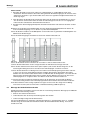
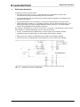
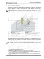
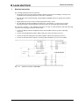
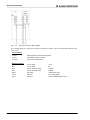
Fig. 7.1-2
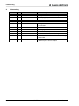
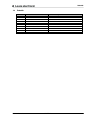
Electrical connection MS, RES/ML
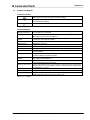
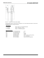
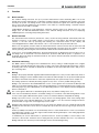
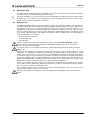
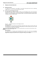
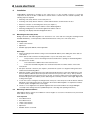
The following signals are expected or issued on the interface cables of the local and machine interface with
cable colors.:
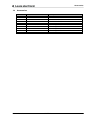
Local interface:
34
L1 input
Muting signal from reflective light barrier
L5 input
Reset button against +24VDC
L5 output
Muting indicator against 0V
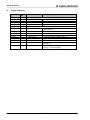
Machine interface
Brown
Power supply
+24V
Blue
Power supply
0V
Grey
Safety switching output
OSSD1
Pink
Safety switching output
OSSD2
White
M4 output
OSSD state / Error
Yellow
M5 input
PLC muting signal
Green
M2 input
Optional EDM feedback circuit
CPSET-M20
Leuze electronic