1
MEASUREMENTS
4 MEASUREMENTS
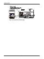
4.1 Voltage drop across PE conductor / resistance of PE conductor
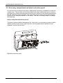
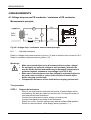
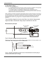
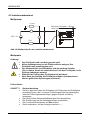
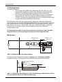
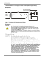
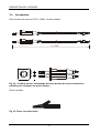
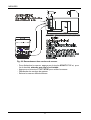
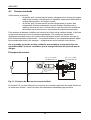
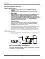
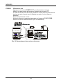
Measurement principle
A
Rt.l.
L1
L2
L3
N
∼
11 V
V
Fuse
Rint.
PE
2
S = 4 mm (example)
Rint.
Fuse
Rt.l.
+
∼
PE collector
UPE (RPE)
230 V
50 Hz
_
Fig. 06. Voltage drop / resistance measurement principle
Rt.l. ......... test lead resistance
Result in voltage drop measurement is given in (V) and is scaled to test current of 10 A.
Result in resistance measurement is given in (Ω).
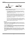
Warnings!
•
•
•
•
Make sure tested object to be disconnected from mains voltage!
Do not apply any external voltage to test terminals, internal fuse
may be blown and the instrument may be damaged! (Instrument is
protected against extraneous overvoltage up to 250 V AC)
Make sure contact between test tips (alligator) and tested object to
be good (remove oxide or colour at the surface of tested object
before carrying out the test)!
Compensate resistance of test leads before carrying out the test!
Test procedure
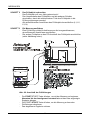
STEP 1
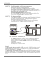
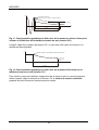
Prepare the instrument
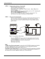
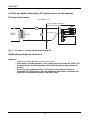
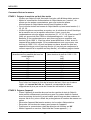
- Place it into such position that both test points of tested object will be
reachable by the test tips (take into account the 2 m long test leads) or
use optional test lead extensions.
- Connect the instrument to mains voltage via mains cord.
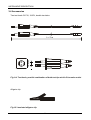
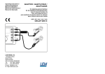
- Connect test leads to terminals of the instrument.
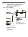
- Select UPE or RPE function setting rotary switch to UPE or RPE position.
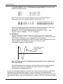
- Switch on the instrument, initial display state is present (- - -).
10