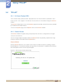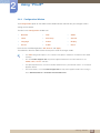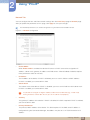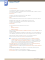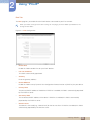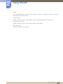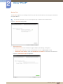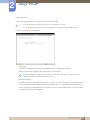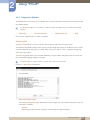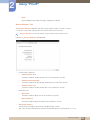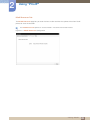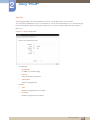
1
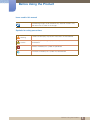
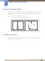
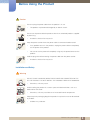
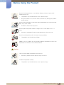
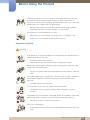
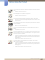
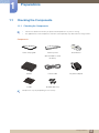
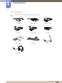
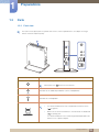
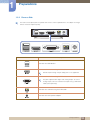
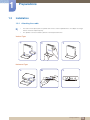
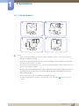
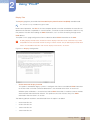
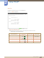
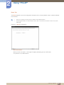
User Manual NX-N2 The color and the appearance may differ depending on the product, and the specifications are subject to change without prior notice to improve the performance. BN46-00400A-02 Table Of Contents BEFORE USING THE PRODUCT PREPARATIONS USING "PCOIP" 4 Copyright 5 5 Icons used in this manual Symbols for safety precautions 6 Securing the Installation Space 6 Precautions for storage 7 Safety Precautions 7 8 10 Electricity and Safety Installation and Safety Operation and Safety 14 Checking the Components 14 Checking the Components 16 Parts 16 18 Front view Reverse Side 19 Installation 19 20 21 Attaching the cradle Attaching Products Anti-theft Lock 22 What is a "PC over IP"? 23 Connection to Use "PCoIP" 23 24 25 25 26 27 28 Connection Using the DP Cable Connecting to a Secondary Monitor Connecting to Headphones Connecting a Microphone LAN Connection Connecting USB Devices Connecting the Power 29 Connect to the host PC using a LAN cable Table Of Contents 2 Table Of Contents 30 "PCoIP" 30 30 31 32 47 51 53 60 62 63 64 65 On Screen Display (OSD) Connect Screen OSD Options Menu Configuration Window Diagnostics Window Information Window User Settings Window Password Window Wake On LAN Wake on USB OSD Logo Upload Firmwre Update TROUBLESHOOTING GUIDE 66 Requirements Before Contacting Samsung Customer Service Center 66 Check the following. SPECIFICATIONS 67 General 68 Power consumption 69 Contact SAMSUNG WORLD WIDE 74 Responsibility for the Pay Service (Cost to Customers) 74 74 75 Not a product defect A Product damage caused by customer's fault Others 76 Correct Disposal 76 Correct Disposal of This Product (Waste Electrical & Electronic Equipment) Correct disposal of batteries in this product APPENDIX 76 INDEX Table Of Contents 3 Before Using the Product Copyright The contents of this manual are subject to change without notice to improve quality. © 2014 Samsung Electronics Samsung Electronics owns the copyright for this manual. Use or reproduction of this manual in parts or entirety without the authorization of Samsung Electronics is prohibited. The SAMSUNG logo is a registered trademark of Samsung Electronics. Microsoft and Windows are registered trademarks of Microsoft Corporation. VESA, DPM and DDC are registered trademarks of the Video Electronics Standards Association. An administration fee may be charged if either (a) an engineer is called out at your request and there is no defect in the product (i.e. where you have failed to read this user manual). (b) you bring the unit to a repair centre and there is no defect in the product (i.e. where you have failed to read this user manual). The amount of such administration charge will be advised to you before any work or home visit is carried out. Before Using the Product 4 Before Using the Product Icons used in this manual The following images are for reference only. Real-life situations may differ from what is shown in the images. Symbols for safety precautions Warning A serious or fatal injury may result if instructions are not followed. Caution Personal injury or damage to properties may result if instructions are not followed. Activities marked by this symbol are prohibited. Instructions marked by this symbol must be followed. Before Using the Product 5 Before Using the Product Securing the Installation Space Ensure some space around the product for ventilation. An internal temperature rise may cause fire and damage the product. Be sure to allow the amount of space as shown below or greater when installing the product. The exterior may differ depending on the product. This product can be installed in portrait or landscape orientation. 3.93 inches (10 cm) 3.93 inches (10 cm) 3.93 inches (10 cm) 3.93 inches (10 cm) 3.93 inches (10 cm) Precautions for storage For information on how to clean the inside of the product, contact the service center (page 69) first. (A service fee will be charged.) Before Using the Product 6 Before Using the Product Safety Precautions The following images are for reference only. Real-life situations may differ from what is shown in the images. Electricity and Safety Warning Do not use a damaged power cable or plug, or a loose power socket. An electric shock or fire may result. Do not plug many products into the same power socket. Otherwise, the socket may overheat and cause a fire. Do not touch the power cable with wet hands. Otherwise, an electric shock may result. Insert the power cable all the way in so it is not loose. An unstable connection may cause a fire. ! Ensure you connect the power cable to a grounded power socket. (type 1 insulated devices only). ! An electric shock or injury may result. Do not bend or pull the power cable with force. Do not weigh the power cable down with a heavy object. A damaged power cord may cause an electric shock or fire. Do not place the power cable or product near heat sources. An electric shock or fire may result. If the power cable pins or power outlet is covered with a foreign substance (dust, etc.), wipe it off using a dry cloth. ! Otherwise, a fire may result. Before Using the Product 7 Before Using the Product Caution Do not unplug the power cable when the product is in use. The product may become damaged by an electric shock. Do not use the power cable for products other than authorized products supplied by Samsung. ! An electric shock or fire may result. Keep the power socket where the power cable is connected unobstructed. If any problem occurs in the product, unplug the power cable to completely cut the power to the product. You cannot cut the power off completely using only the power button on the product. Hold the plug when disconnecting the power cable from the power socket. An electric shock or fire may result. ! Installation and Safety Warning DO NOT PLACE CANDLES, INSECT REPELLANTS OR CIGARETTES ON TOP OF THE PRODUCT. DO NOT INSTALL THE PRODUCT NEAR HEAT SOURCES. Otherwise, a fire may result. Avoid installing the product in a narrow space with bad ventilation, such as a bookshelf or wall closet. Otherwise, a fire may result due to an increased internal temperature. Keep the plastic packaging bag for the product in a place that cannot be reached by children. Children may suffocate. Before Using the Product 8 Before Using the Product Do not install the product on an unstable or vibrating surface (insecure shelf, sloped surface, etc.). The product may fall and break or cause a personal injury. Using the product in an area with excess vibration may damage the product or cause a fire. Do not install the product in a vehicle or a place exposed to dust, moisture (water drips, etc.), oil, or smoke. An electric shock or fire may result. Do not expose the product to direct sunlight, heat, or a hot object such as a stove. Otherwise, the product lifespan may be reduced, or a fire may result. Do not install the product within the reach of young children. The product may fall and injure children. Edible oil, such as soybean oil, can damage or deform the product. Do not install the product in a kitchen or near a kitchen counter. Caution Take care not to drop the product when moving it. Otherwise, product failure or personal injury may result. Put down the product carefully. The product may fall and break or cause a personal injury. Before Using the Product 9 Before Using the Product SAMSUNG ! Installing the product in an unusual place (a place exposed to a lot of fine dust, chemical substances, extreme temperatures or a significant presence of moisture, or a place where the product will operate continuously for an extended period of time) may seriously affect its performance. Be sure to consult Samsung Customer Service Center (page 69) before installation if you want to install the product at such a place. Do not leave or install the product on the floor. Abrupt force such as kicking or extra weight such as stepping on the product may cause a product failure or personal injury. Operation and Safety Warning High voltage runs through the product. Do not attempt to disassemble, repair, or modify the product on your own. An electric shock or fire may result. Contact Samsung Customer Service Center (page 69) for repair. Before moving the product, turn off the power and disconnect the power cable and all other connected cables. Otherwise, the power cord may be damaged and a fire or electric shock may result. If the product generates a strange noise, a burning smell, or smoke, remove the power cable immediately and contact Samsung Customer Service Center (page 69). An electric shock or fire may result. Ensure children do not sit on the product or kick the product. The product may fall, and your child may become injured or seriously harmed. If the product falls or the exterior is damaged, power off the product, remove the power cable, and contact Samsung Customer Service Center (page 69). Otherwise, an electric shock or fire may result. Do not sit on the product. The product housing or connectors may get damaged or personal injury may result. Before Using the Product 10 Before Using the Product During a lightning or thunderstorm, power off the product and remove the power cable. An electric shock or fire may result. Do not drop objects on the product or apply impact. An electric shock or fire may result. Do not move the product holding only by the power cable or a signal cable. Otherwise, the cable may be damaged and product failure, an electric shock or fire may result. If a gas leakage is found, do not touch the product or power cable. Also, ventilate the area immediately. Sparks can cause an explosion or fire. Do not use or keep combustible spray or an inflammable substance near the product. An explosion or fire may result. Do not insert metallic objects such as a chopstick, coin or hair pin into the vent or ports of the product. Do not insert inflammable objects such as paper or a match into the vent or ports of the product. If water or any foreign substance enters the product, be sure to power off the product, remove the power cable, and contact Samsung Customer Service Center (page 69). Product failure, an electric shock or fire may result. Do not place objects containing liquid (vases, pots, bottles, etc) or metallic objects on top of the product. If water or any foreign substance enters the product, be sure to power off the product, remove the power cable, and contact Samsung Customer Service Center (page 69). Product failure, an electric shock or fire may result. Before Using the Product 11 Before Using the Product Caution Disconnect the power cable from the power socket if you do not plan on using the product for an extended period of time (vacation, etc.). Otherwise, a fire may result from accumulated dust, overheating, an electric shock, or electric leakage. Do not put DC power adapters together. Otherwise, a fire may result. Remove the plastic bag from the DC power adapter before you use it. Otherwise, a fire may result. Do not let water enter the DC power adapter or get the adapter wet. An electric shock or fire may result. Avoid using the product outdoors where it can be exposed to rain or snow. Be careful not to get the DC power adapter wet when you wash the floor. Do not put the DC power adapter near to any heating apparatus. Otherwise, a fire may result. Keep the DC power adapter in a well-ventilated area. ! Do not use humidifiers or stoves around the product. An electric shock or fire may result. Store the small accessories used with the product out of reach of children. ! Before Using the Product 12 Before Using the Product Do not place heavy objects on the product. Product failure or personal injure may result. Do not increase the volume too high when using headphones (earphones). Sound particularly at a higher volume could potentially affect long-term hearing. Before Using the Product 13 1 1.1 Preparations Checking the Components 1.1.1 Checking the Components Contact the dealer from whom you purchased the product if any item is missing. The appearance of the components and items sold separately may differ from the image shown. Components Quick setup guide Warranty card User Manual (Not available in some locations) Product Power cable Cradle SCREW (M4 X L8) DC power adapter Components may vary depending on the country. 1 Preparations 14 1 Preparations Items sold separately The following items can be purchased at your nearest retailer. LAN cable USB cable HDMI-DVI cable DVI cable DVI-RGB cable DP cable Mouse (USB) Keyboard MIC Headphone 1 Preparations 15 1 1.2 Preparations Parts 1.2.1 Front view The color and shape of parts may differ from what is shown. Specifications are subject to change without notice to improve quality. A Ports Description Power on or off the product. Please press the button for two seconds. Connect to an audio output device such as headphones. Connect to a microphone. Connect to a USB device. It is recommended to connect a keyboard and mouse to the [ (2.0)] ports. Make sure an external hard drive is connected to the dedicated [ (2.0) HDD] port. It is recommended to use an externally powered portable hard drive that has a power adapter. 1 Preparations 16 1 Preparations Ports Description Connect to a USB device. A Speaker 1 Preparations 17 1 Preparations 1.2.2 Reverse Side The color and shape of parts may differ from what is shown. Specifications are subject to change without notice to improve quality. Ports Description Connect to a USB device. Connect to the monitor using the DP cable. Sound output through the [DP OUT] port is not supported. Connect to the monitor using the DVI cable. The port supports both digital and analog output. To use an analog output, connect a device to the port using a DVI-RGB cable (sold separately). Connect to a network using the LAN cable. Connect to the DC power adapter. 1 Preparations 18 1 1.3 Preparations Installation 1.3.1 Attaching the cradle The color and shape of parts may differ from what is shown. Specifications are subject to change without notice to improve quality. This product can be installed in portrait or landscape orientation. Vertical Type Horizontal Type 1 Preparations 19 1 Preparations 1.3.2 Attaching Products 4 A Notes When attaching the product to a monitor, make sure there is at least a 10 cm gap around the product and monitor assembly. When attaching the product to a monitor, it is recommended to attach the product to the cradle horizontally. Do not attach it vertically. The dimensions of the product are 100 x 100 mm according to VESA standards. Make sure to use screws that are VESA compliant. Using screws not compatible with the VESA standards may damage the product or cause the attachment to fall off. Samsung is not responsible for damages associated with not using VESA compliant parts. Do not use screws that do not comply with the VESA standards. To attach the product to the monitor, align and firmly fasten the cradle ( A ) to the slots on the monitor. 1 Preparations 20 1 Preparations 1.3.3 Anti-theft Lock An anti-theft lock allows you to use the product securely even in public places. The locking device shape and locking method depend on the manufacturer. Refer to the user guide provided with your anti-theft locking device for details. The lock device is sold separately. To lock an anti-theft locking device: 1 2 Fix the cable of your anti-theft locking device to a heavy object such as a desk. 3 4 Insert the Kensington Lock into the security slot on the side of the product. Put one end of the cable through the loop on the other end. Lock the locking device. An anti-theft locking device can be purchased separately. Refer to the user guide provided with your anti-theft locking device for details. Anti-theft locking devices can be purchased at electronics retailers or online. 1 Preparations 21 2 2.1 Using "PCoIP" What is a "PC over IP"? Rack Mount Server Work Station The product receives images from the encoded file on the server PC via LAN and then decodes and displays the images on the connected display devices. If only one display device is connected to the DP port on the product, the product can support the single display at a maximum resolution of 2560 x 1600. If two display devices are simultaneously connected to the DP and DVI-I OUT ports, the product can support both displays at a maximum resolution of 1920 x 1200. The product connects to a server PC. This ensures improved security and allows you to access the Internet, create documents and edit images using the server PC. USB ports are provided allowing you to connect and use external input devices. 2 Using "PCoIP" 22 2 2.2 Using "PCoIP" Connection to Use "PCoIP" Do not connect the power cable before connecting all other cables. Ensure you connect a source device first before connecting the power cable. 2.2.1 Connection Using the DP Cable DP OUT 1 DP IN Connect the DP cable to the [DP OUT] port on the back of the product and the [DP IN] port on the PC. Sound output through the [DP OUT] port is not supported. 2 Using "PCoIP" 23 2 Using "PCoIP" 2.2.2 1 Connecting to a Secondary Monitor DVI-I OUT DVI IN DVI-I OUT RGB IN DVI-I OUT HDMI IN Connect the DVI, DVI-RGB or DVI-HDMI cable (sold separately) to the [DVI-I OUT] port on the back of the product and the [DVI IN], [RGB IN] or [HDMI IN] port on the PC. The [DVI-I OUT] port is for a secondary monitor. Connect the [DVI-I OUT] port to a secondary monitor when dual display mode is required. Use a DVI-RGB cable (sold separately) if you want to display analog output. Use a DVI or DVI-HDMI cable (sold separately) if you want to display digital output. 2 Using "PCoIP" 24 2 Using "PCoIP" 2.2.3 Connecting to Headphones 1 Connect the headphones to [ ] on the front of the product. 2.2.4 Connecting a Microphone 1 Connect the microphone to [ ] on the front of the product. 2 Using "PCoIP" 25 2 Using "PCoIP" 2.2.5 LAN Connection LAN 1 Connect the LAN cable to the [LAN] port at the back of the product. 2 Using "PCoIP" 26 2 Using "PCoIP" 2.2.6 Connecting USB Devices (2.0) HDD (2.0) A 1 Connect USB devices to the ports on the front or back of the product. Keyboard and mouse devices are required to connect to [ When connecting an external hard drive, use the [ (2.0) HDD] port. We recommend that you use an external hard drive with its own power adapter. Make sure a device that requires over 0.5 A such as an external hard drive is connected to the dedicated [ (2.0) HDD] port. A Ports [ [ (2.0)]. Maximum output current for [ (2.0) HDD] When using (2.0)] + [ (2.0) HDD] at the same time 1.0 A When using (2.0) HDD] only 1.5 A 2 Using "PCoIP" 27 2 Using "PCoIP" 2.2.7 Connecting the Power Connect the power cable to the DC power adapter. Then, connect the DC power adapter to the [DC 14V] port on the back of the product. Next, connect the power cable to the power outlet. DC 14V The input voltage is switched automatically. 2 Using "PCoIP" 28 2 2.3 Using "PCoIP" Connect to the host PC using a LAN cable Host PC Rack Mount Server Work Station HUB LAN Cable NX-N2 1 Host PC 2 HUB 3 LAN Cable 4 1 Connect the power cord to the power terminal at the back of the product. 2 Connect the mouse and the keyboard to the USB ports. 3 Connect the LAN port on the back of the product and the HUB. 4 Connect the HUB and the LAN port of the host PC. NX-N2 The host PC must have an IP address. After connecting the LAN and setting the IP address, you can view the host PC screen on the monitor. Use the USB port to connect an external storage device (DSC, MP3, external storage, etc.). Connecting one Host PC to many client device is possible only when virtualization solution like vmware is installed in Host PC. 2 Using "PCoIP" 29 2 2.4 Using "PCoIP" "PCoIP" 2.4.1 On Screen Display (OSD) The On Screen Display (OSD) local GUI is displayed to the user when the device is powered on and a PCoIP session is not in progress. The OSD lets the user connect to a host device through the Connect window. The Connect window allows access to the Options page which provides some of the functions provided by the Administrative Web Interface. To access the Options page, click the Options menu on the Connect window. 2.4.2 Connect Screen The Connect window will appear during startup except when the client is configured for a managed startup or auto-reconnect. You can change the logo that appears above the Connect button by uploading a replacement image through the Administrative Web Interface Upload menu. Connect Button Click the Connect button to start a PCoIP session. When the PCoIP connection is pending, the OSD local GUI displays a "Connection Pending" message. When the connection is established, the OSD local GUI will disappear and the session image will appear. Figure 2-1: OSD Connect Screen (Connecting) 2 Using "PCoIP" 30 2 Using "PCoIP" 2.4.3 OSD Options Menu Selecting the Options menu will display a list of selections. The OSD Options menu contains: Configuration This option lets you configure various settings for the device such as network settings, session type, language, and other settings. Diagnostics This option helps you troubleshoot the device. Information This option lets you view certain details about the device. User Settings This option lets the user define certificate checking mode, Mouse, Keyboard, Display Topology, as well as the PCoIP protocol image quality. Selecting an option will display a settings window. Figure 2-2: OSD Options Menu 2 Using "PCoIP" 31 2 Using "PCoIP" 2.4.4 Configuration Window The Configuration option on the Administrative Web Interface and OSD lets you configure various settings for the device. The tabs in the Configuration window are: Network IPv6 SCEP Label Discovery Session Language Power Display Access Audio Reset Each tab has the following buttons: OK, Cancel, and Apply. These buttons allow the administrator to accept or cancel the changes made. The OSD configuration options are a subset of the options available in the Administrative Web Interface. Visit the Teradici Support Site: http://techsupport.teradici.com for further details on the SCEP, Label, Access and tabs. For optimal performance, install the Teradici Audio Driver on your VM and select it as the default playback device. For further details, visit the Teradici Support Site at http://techsupport.teradici.com and log in. Go to Download Center Teradici Virtual Audio Driver. 2 Using "PCoIP" 32 2 Using "PCoIP" Network Tab You can configure the host and client network settings from the Initial Setup page or Network page. After you update the parameters on this page, click Apply to save your changes. The Network parameters can also be configured using the Administrative Web Interface. Figure 2-3: Network Configuration Enable DHCP When Enable DHCP is enabled, the device will contact a DHCP server to be assigned an IP address, subnet mask, gateway IP address and DNS servers. When disabled, the device requires these parameters to be set manually. IP Address The IP address of the device. If DHCP is disabled, you must set this field to a valid IP address. If DHCP is enabled, you cannot edit this field. Subnet Mask The subnet mask of the device. If DHCP is disabled, you must set this field to a valid subnet mask. If DHCP is enabled, you cannot edit this field. It is possible to configure an illegal IP address/subnet mask combination (e.g., invalid mask) making the device unreachable. Ensure you set the subnet mask properly. Gateway The gateway IP address of the device. If DHCP is disabled, this field is required. If DHCP is enabled, you cannot edit this field. Primary DNS Server The primary DNS IP address of the device. This field is optional. If the DNS server IP address is configured using the Connection Manager, the address may be set as an FQDN instead of an IP address. 2 Using "PCoIP" 33 2 Using "PCoIP" Secondary DNS Server The secondary DNS IP address of the device. This field is optional. If the DNS server IP address is configured using the Connection Manager, the address may be set as an FQDN instead of an IP address. Domain Name The domain name used (e.g., 'domain.local'). This field is optional. This field specifies the host or domain of the client. FQDN The Fully Qualified Domain Name for the host or client. The default value is pcoip-host-<MAC> or pcoipportal-<MAC> where <MAC> is the MAC address of the host or client. The domain name is appended if used (e.g., pcoip-host-<MAC>.domain.local). This field is read-only on this page. Ethernet Mode Lets you configure the Ethernet mode of the host or client as: Auto 100 Mbps Full-Duplex 10 Mbps Full-Duplex When you choose 10 Mbps Full-Duplex or 100 Mbps Full-Duplex and then click Apply, a warning message will appear. "Warning: When Auto-Negotiation is disabled on the PCoIP device, it must also be disabled on the switch. Additionally, the PCoIP device and switch must be configured to use the same speed and duplex parameters. Different parameters may result in a loss of network connectivity. Are you sure you want to continue?" Click OK to change the parameter. You should always set the Ethernet Mode to Auto and only use 10 Mbps Full-Duplex or 100 Mbps Full-duplex when the other network equipment (i.e., switch) is also configured to operate at 10 Mbps Full-Duplex or 100 Mbps Full-duplex. An improperly configured Ethernet Mode may result in the network operating at half-duplex which is not supported by the PCoIP protocol. The session will be severely degraded and eventually dropped. Enable 802.1X Security: If the connected network supports 802.1x, Enable 802.1X Security should be enabled and security-authenticated devices can only be used. If Enable 802.1X Security is enabled, configure the Authentication, Identity and Client Certificate settings. TLS (Transport Layer Security) is only supported as an authentication protocol at present. Identity: Enter the product ID that will be used on the network. Client Certificate: Select a certificate uploaded from the Certificate Upload page. 2 Using "PCoIP" 34 2 Using "PCoIP" IPv6 Tab The IPv6 page lets you enable IPv6 for PCoIP devices connected to your IPv6 network. When you make a change to one of the settings on this page, you must reboot your device for the change to take effect. Figure 2-4: IPv6 Configuration Enable IPv6 Enable this field to enable IPv6 for your PCoIP devices. Link Local Address This field is automatically populated. Gateway Enter the gateway address. Enable DHCPv6 Enable this field to set up Dynamic Host Configuration Protocol version 6 (DHCPv6) for your device. Primary DNS The primary DNS IP address of the device. If DHCPv6 is enabled, this field is automatically populated by the DHCPv6 server. Secondary DNS The secondary DNS IP address of the device. If DHCPv6 is enabled, this field is automatically populated by the DHCPv6 server. Domain Name The domain name used (e.g., 'domain.local') for the host or client. If DHCPv6 is enabled, this field is automatically populated by the DHCPv6 server. 2 Using "PCoIP" 35 2 Using "PCoIP" FQDN The fully qualified domain name for the host or client. If DHCPv6 is enabled, this field is automatically populated by the DHCPv6 server. Enable SLAAC Enable this field to set up stateless address auto-configuration (SLAAC) for your devices. Enable Manual Address Enable this field to set up a manual (static) address for the device. Manual Address Enter the IP address for the device. 2 Using "PCoIP" 36 2 Using "PCoIP" Label Tab The Label page is available from the host or client. The Label page lets you add information for the device. The Portal Label parameters can also be configured using the Administrative Web Interface. Figure 2-5: Label Configuration PCoIP Device Name If the PCoIP Device Name allows the administrator to give the Host or Portal a logical name. The default value is pcoip-host-MAC or pcoip-portal-MAC where MAC is the MAC address of the Host or Portal. PCoIP Device Description A description and additional information such as the location of the endpoint for the device. The firmware does not use this field. It is provided for administrator use only. Generic Tag Generic tag information about the device. The firmware does not use this field. It is provided for administrator use only. 2 Using "PCoIP" 37 2 Using "PCoIP" Discovery Tab Use the settings on the Discovery page to erase the discovery of hosts and clients in your PCoIP system and dramatically reduce the configuration and maintenance effort for complex systems. This discovery mechanism is independent of DNS SRV discovery. For SLP discovery to work, routers must be configured to forward multicast traffic between subnets. DNS-SRV Discovery is the recommended discovery mechanism because most deployments do not allow this. Figure 2-6: Discovery Configuration Enable Discovery If the Enable Discovery option is enabled, the device will dynamically discover peer devices using SLP Discovery without requiring prior information on their locations in the network. This can dramatically reduce configuration and maintenance effort for complex systems. SLP discovery requires routers configured to allow multicast. DNS-SRV Discovery is the recommended method. 2 Using "PCoIP" 38 2 Using "PCoIP" Session Tab The Session page lets you configure how the host or client device connects to or accepts connections from peer devices. The Session parameters can also be configured using the Administrative Web Interface. Figure 2-7: Session Configuration Connection Type Select Direct to Host from the Session page to display the following setting items: Direct to Host: Connect to a PC or Work Station that has a Host Card installed. DNS Name or IP Address: Enter the DNS Name or IP Address of the server to connect to. Figure 2-8: Connection Type Configuration 2 Using "PCoIP" 39 2 Using "PCoIP" When you select a View Connection Server type from the Session page, specific configuration options will appear. View Connection Server: Connect to the VMware VDI (Virtual Desktop Infrastructure) server. VMware VDI is a virtual desktop solution. DNS Name or IP Address: Enter the VMware View Connection Server's DNS Name or IP Address. Figure 2-9: Connection Type Configuration Advanced Visit the Teradici Support Site: http://techsupport.teradici.com for further details. 2 Using "PCoIP" 40 2 Using "PCoIP" Language Tab The Language page lets you change the user interface language. This setting affects the local OSD GUI. It is only available on the client. The Language parameters can also be configured using the Administrative Web Interface. Figure 2-10: Language Configuration Language Configure the OSD language. This setting determines the language for OSD only. It does not affect the language setting for the actual user session. Supported languages: English, French, German, Greek, Spanish, Italian, Portuguese, Korean, Japanese, Traditional Chinese, Simplified Chinese Keyboard Layout Change the layout of the keyboard. When the user starts a session, this setting is controlled through the virtual machine. If the Windows Group Policy Object (GPO) is set to allow the keyboard layout setting, the setting is applied during the session of the user. If the Windows GPO is not set to allow the setting, the setting is not applied. 2 Using "PCoIP" 41 2 Using "PCoIP" Power Tab Figure 2-11: Power Configuration OSD Screen-Saver Timeout (when not connected to a session): Connected monitors will go into standby mode if left idle for a specified period of time (in seconds). Enter "0" if you do not want to use the standby mode function. Display Suspend Timeout (when connected to a session): Connected monitors will go into standby mode if left idle for a specified period of time (in seconds). Enter "0" if you do not want to use the standby mode function. 2 Using "PCoIP" 42 2 Using "PCoIP" Display Tab The Display page lets you enable the Extended Display Identification Data(EDID) override mode. This function is only available through the OSD. Under normal operation, the GPU in the host computer queries a monitor attached to the zero client to determine the monitor's capabilities. In some situations, a monitor may be connected to a client in a way that prevents the client from reading the EDID information, such as when connecting through certain KVM devices. The options in this page configure the client to advertise default EDID information to the GPU. Enabling display override forces the default monitor display information to be used which may not be compatible with the connected monitor resulting in a blank monitor. Only enable display override when there is no valid EDID information and monitor display characteristics are known. Figure 2-12: Display Configuration Enable Attached Display Override This option is intended for legacy systems. It configures the client to send default EDID information to the host when a monitor cannot be detected or is not attached to the client. In versions of Windows prior to Windows 7, once the host had no EDID information, it would assume no monitors were attached and would never recheck. This option ensures that the host always has EDID information when the client is in session. The following default resolutions are advertised when this option is enabled: 2560x1600 @60 Hz 2048x1152 @60 Hz 1920x1440 @60 Hz 1920x1200 @60 Hz 2 Using "PCoIP" 43 2 Using "PCoIP" 1920x1080 @60 Hz 1856x1392 @60 Hz 1792x1344 @60 Hz 1680x1050 @60 Hz 1600x1200 @60 Hz 1600x900 @60 Hz 1440x900 @60 Hz 1400x1050 @60 Hz 1366x768 @60 Hz 1360x768 @60 Hz 1280x1024 @60 Hz 1280x960 @60 Hz 1280x800 @60 Hz 1280x768 @60 Hz 1280x720 @60 Hz 1024x768 @60 Hz 848x480 @60 Hz 800x600 @60 Hz 640x480 @60 Hz If Enable Attached Display Override is activated, all displays connected to the client are set to the default resolution of 1024 x 768. Enable Display Cloning This feature allows you to display the same screen on two monitors simultaneously while in dual monitor mode. 2 Using "PCoIP" 44 2 Using "PCoIP" Audio Tab Configure the audio settings (e.g., mic and headphones). Figure 2-13: Audio Configuration Enable Local USB Audio Driver Sound will play from the internal speakers when playing music found on the server. e internal speakers. Sound output and connected devices Connected devices Enable Local USB Audio Driver Device Type Sound output USB headphones + earphones Select ( ) USB USB headphones USB headphones + earphones Select ( ) Analog earphone Earphones only Deselect ( ) - earphone - Deselect ( ) - Internal speakers 2 Using "PCoIP" 45 2 Using "PCoIP" Reset Tab The Reset page lets you reset configuration and permissions to factory default values stored in onboard flash memory. Reset can also be initiated using the Administrative Web Interface. Resetting parameters to factory default values does not revert the firmware or clear the custom OSD logo. Figure 2-14: Reset Configuration Reset Parameters When you click this button, a message will appear prompting you for confirmation. This prevents an accidental reset. 2 Using "PCoIP" 46 2 Using "PCoIP" 2.4.5 Diagnostics Window The Diagnostic menu contains links to pages with run-time information and functions that may be useful for troubleshooting. The Diagnostic options in the OSD are a subset of those available through the Administrative Web Interface. Event Log Session Statistics PCoIP Processor Ping Each tab has a Close button to close the window. Event Log Tab The Event Log page lets you view and clear event log messages from the host or client. The Administrative Web Interface allows you to change the log filter setting on the device which controls the level of detail of the messages in the log. When you set the filter to “terse”, the device will log short and concise messages. The Event Log page allows you to enable and define syslog to collect and report events that meet the IETF standard for logging program messages. The Event Log can also be initiated using the administrative web interface. Figure 2-15: Event Log Configuration View event log messages The View event log messages field displays log messages with time stamp information. There are two buttons available. Refresh Selecting the Refresh button refreshes the event log messages displayed. 2 Using "PCoIP" 47 2 Using "PCoIP" Clear Click to delete all event log messages stored on the device. Session Statistics Tab The Session Statistics page lets you view current statistics when a session is active. If a session is not active, you can view the statistics from the last session. Session Statistics can also be viewed using the administrative web interface. Figure 2-16: Session Statistics Configuration PCoIP Packets Statistics PCoIP Packets Sent The total number of PCoIP packets sent in the current/last session. PCoIP Packets Received The total number of PCoIP packets received in the current/last session. PCoIP Packets Lost The total number of PCoIP packets lost in the current/last session. Bytes Statistics Bytes Sent The total number of bytes sent in the current/last session. Bytes Received The total number of bytes received in the current/last session. Round Trip Latency The minimum, average, and maximum roundtrip PCoIP system (e.g., host to client and then back to host) and network latency in milliseconds (+/- 1 ms). 2 Using "PCoIP" 48 2 Using "PCoIP" PCoIP Processor Tab The PCoIP Processor page lets you reset the host or client and view the uptime of the client PCoIP processor since the last boot. The PCoIP Processor Uptime can also be viewed in the administrative web interface. Figure 2-17: PCoIP Processor Configuration 2 Using "PCoIP" 49 2 Using "PCoIP" Ping Tab The Ping page allows you to ping a device to see if it is reachable across the IP network. This may help you determine if a host is reachable. As a result of firmware releases 3.2.0 and later forcing the “do not fragment” flag in the ping command, you can use this feature to determine the maximum MTU size. Figure 2-18: Ping Configuration Ping Settings Destination IP Address or FQDN to ping Interval Interval between ping packets Packet Size Size of the ping packet Packets Sent Number of ping packets transmitted Received Number of ping packets received 2 Using "PCoIP" 50 2 Using "PCoIP" 2.4.6 Information Window The Information page lets you see details about the device. The Administrative Web Interface shows version, VPD, and attached device information. The OSD lets you view the device version information. The Version page lets you view the hardware and firmware version details for a device. Figure 2-19: Version Configuration VPD Information Vital Product Data (VPD) is information set by the factory to uniquely identify each Portal or Host. MAC Address Host/client unique MAC address Unique Identifier Host/client unique identifier Serial Number Host/client unique serial number Firmware Part Number Part number of the current firmware Hardware Version Host/client hardware version number Firmware Information The Firmware Information reflects the current PCoIP firmware details. Firmware Version Version of the current firmware Firmware Build ID Revision code of the current firmware 2 Using "PCoIP" 51 2 Using "PCoIP" Firmware Build Date Build date for the current firmware PCoIP Processor Family The Tera family name is displayed. Tera is a host processor from Teradici. This product uses a TERA2321 from the newer generation Tera2 host processor family and is displayed as Tera2. PCoIP Processor Revision The silicon revision of the PCoIP processor. Revision B of the silicon is denoted by a 1.0. Bootloader Information The Bootloader information reflects the current PCoIP bootloader details. Bootloader Version Version of the current bootloader Bootloader Build ID Revision code of the current bootloader Bootloader Build Date Build date of the current bootloader 2 Using "PCoIP" 52 2 Using "PCoIP" 2.4.7 User Settings Window The User Settings page allows you to access tabs to define the Certificate Checking Mode, the mouse and keyboard settings, PCoIP protocol image quality, and display topology. The tabs in the User Settings menu are: Certificate Mouse Keyboard Image Display Topology Touch Screen Certificate Tab In this tab, select the next steps to take when the security for connection to a server cannot be verified. It is recommended to change this setting only with approval from the system manager. Figure 2-20: Certificate Configuration Never connect to untrusted servers: Select this option if you do not want to connect to a server that has no certificate or has an untrusted certificate. Warn before connecting to untrusted servers: Select this option if you want to display a warning prompt before connecting to an untrusted server. Do not verify server identity certificates: Select this option if you want to permit connections with a server without verifying the server ID certificate. 2 Using "PCoIP" 53 2 Using "PCoIP" Mouse Tab The Mouse page lets you change the mouse cursor speed settings for the OSD sessions. The OSD mouse cursor speed setting does not affect the mouse cursor settings when a PCoIP session is active unless the Local Keyboard Host Driver function is being used. Refer to the "PCoIP Host Software for Windows User Guide: TER0810001" for more details. This function is only available through the OSD. It is not available in the Administrative Web Interface. Figure 2-21: Mouse Configuration Mouse Speed Configure the speed of the mouse cursor. You can also configure the mouse speed through the PCoIP host software. Refer to the "PCoIP Host Software for Windows User Guide: TER0810001" for more details. 2 Using "PCoIP" 54 2 Using "PCoIP" Keyboard Tab The Keyboard page lets you change the keyboard repeat settings for the OSD session. The keyboard settings do not affect the keyboard settings when a PCoIP session is active unless the Local Keyboard Host Driver function is used. Refer to the "PCoIP Host Software for Windows User Guide: TER0810001" for more details. This setting is only available through the OSD. It does not appear on the Administration Web Interface. You can also configure the keyboard repeat settings through the PCoIP host software. Refer to the "PCoIP Host Software for Windows User Guide: TER0810001" for more details. Figure 2-22: Keyboard Configuration Keyboard Repeat Delay Lets users configure the client keyboard repeat delay. Keyboard Repeat Rate Lets users configure the client keyboard repeat rate. Repeat Settings Test Box Lets users test the chosen keyboard settings. 2 Using "PCoIP" 55 2 Using "PCoIP" Image Tab The Image page allows you to make changes to the image quality of the PCoIP session. Figure 2-23: Image Configuration Image Quality Preference Use the slider to adjust the balance between image sharpness and smooth motion during a PCoIP session when network bandwidth is limited. This field is also accessible on the host if the PCoIP Host Software is installed. The slider can be found under the Image tab of the host software. 2 Using "PCoIP" 56 2 Using "PCoIP" Display Topology Tab To apply the Display Topology feature to a PCoIP session between a zero client and a PCoIP host, you must have the PCoIP host software installed on the host. Refer to the "PCoIP Host Software for Windows User Guide: TER0810001" for more details. The Display Topology tab has no corresponding menu in the Administration Web Interface. For details about the Display Topology feature for a PCoIP session between a host card and a zero client, refer to the "PCoIP Host Software for Windows User Guide: TER0810001". Always change the Display Topology settings using the Display Topology tab on the zero client OSD Options User Settings interface. Figure 2-24: Display Topology Configuration Enable Configuration The device can be configured with display position, rotation and resolution settings if enabled. The settings are saved when you click Apply or OK and are applied when the device is reset. Display Layout Select whether you want a horizontal or vertical layout for your displays (A and B). This setting should reflect the physical layout of the displays on your desk. Horizontal: Select to arrange A and B horizontally, with A located to the left of B. Vertical: Select to arrange A and B vertically, with A located above B. A maximum of two displays can be enabled at the same time. 2 Using "PCoIP" 57 2 Using "PCoIP" Alignment Select how you want displays A and B aligned when they are different sizes. This setting affects which area of the screen to use when you move the cursor from one display to the other. The alignment options that appear in the drop-down list depend on whether you have selected a horizontal or vertical display layout. Primary Configure which DVI port on the zero client that you want as the primary port. The display that is connected to the primary port becomes the primary display (i.e., the display that contains the OSD menus before you initiate a PCoIP session and the display that is requested for the Windows taskbar after you initiate the session). Port 1: Select to configure DVI-1 port on the zero client as the primary port. Port 2: Select to configure DVI-2 port on the zero client as the primary port. Position Specify which display is physically connected to Port 1 and Port 2. Rotation Configure the rotation of the display in Port 1 and Port 2: No rotation 90˚ clockwise 180˚ rotation 90˚ counter-clockwise Resolution The display resolution can be configured for a PCoIP session between a virtual machine or host and a zero client. The zero client detects the supported display resolutions of the monitor and populates them to the drop-down menu. By default, the native resolution of the display is used. Revert Resets the configurations on this page to their last saved settings. 2 Using "PCoIP" 58 2 Using "PCoIP" Touch Screen Tab The Touch Screen page allows you to configure and calibrate certain settings of an attached Elo TouchSystems touch screen display. The Touch Screen page is only available through the OSD. It is not available in the Administrative Web Interface. Figure 2-25: Touch Screen Configuration Enable right click on hold Select this checkbox to allow users to emulate a right-click when they touch the screen and hold it for a few seconds. If disabled, right-click is not supported. Right click delay Slide the pointer to a position between Long and Short to determine how long a user must touch and hold the screen to emulate a right-click. Touch screen calibration When you first connect the touch screen to the zero client, the calibration program will start. On the touch screen, touch each of the three targets as they appear. To test the calibration, run your finger along the monitor and ensure that the cursor follows it. If it is not successful, the calibration program automatically restarts. Once calibrated, the coordinates are stored in flash. To manually start the calibration program, from the OSD Touch Screen page, click Start. Follow the onscreen prompts. 2 Using "PCoIP" 59 2 Using "PCoIP" 2.4.8 Password Window To use the Password function, configure Options for the zero client using PCoIP MC. Visit the Teradici Support Site: http://techsupport.teradici.com for further details. The Password page lets you update the local administrative password for the device. The Password can be a maximum of 20 characters. This parameter affects the Administrative Web Interface and the local OSD GUI. Take care when updating the client password as the client may become unusable if the password is lost. Figure 2-26: Change Password Configuration Old Password This field must match the current administrative password before you can update the password. New Password The new administrative password for both the administrative web interface and the local OSD GUI. Confirm New Password This field must match the New Password field for the password to be updated. Reset If the client password is lost, you can click the Reset button to request a response code from the client vendor. The challenge code is sent to the vendor. The vendor qualifies the request and returns a response code if authorized by Teradici. When the response code is correctly entered, the password of the client is set to an empty value. You must enter a new password. Contact the client vendor for more information when an authorized password reset is required. This option is not available through the Administrative Web Interface. It is only available through the OSD. 2 Using "PCoIP" 60 2 Using "PCoIP" Figure 2-27: Authorized Password Reset Configuration Details on how to use PCoIP are subject to change without notice. To view the latest information, visit the Teradici website at http://www.teradici.com. 2 Using "PCoIP" 61 2 Using "PCoIP" 2.4.9 Wake On LAN This feature allows you to power on the product by sending a pre-determined command from an external system to the product over a network. Make sure the network is capable of data communication with the PC that sends the command to the product. Ensure you have a program that can generate Wake on LAN signals. Make sure a power supply is always connected to ensure the feature works when the product is turned off. The feature is intended to power on the product. (It does not support the function to power off the product.) Configuring the settings 1 2 Set the product and PC IP addresses to enable the product to connect to the PC over a network. Enter the IP address set for the product in the URL address field on the PC to access the product administrative web page. 3 4 To change the power settings, log in (Log In) and select Configuration Power. Configure the settings to suit the environment in which the product is used. (See the image below.) 2 Using "PCoIP" 62 2 Using "PCoIP" 2.4.10 Wake on USB If you turn off the power after activating Wake On USB on the product administrative web page, the system switches to standby mode. The Wake on USB feature switches the system from standby mode to normal mode if a change to the keyboard or mouse input is detected. Changes include clicking a mouse button or pressing a key on the keyboard. Configuring the settings 1 2 Set the product and PC IP addresses to enable the product to connect to the PC over a network. Enter the IP address set for the product in the URL address field on the PC to access the product administrative web page. 3 4 To change the power settings, log in (Log In) and select Configuration Power. Configure the settings to suit the environment in which the product is used. (See the image below.) 2 Using "PCoIP" 63 2 Using "PCoIP" 2.4.11 OSD Logo Upload Using the OSD Logo Upload page, change the logo displayed on the Teradici OSD. Configuring the settings 1 2 Set the product and PC IP addresses to enable the product to connect to the PC over a network. Enter the IP address set for the product in the URL address field on the PC to access the product administrative web page. 3 Log in (Log In) and select Upload OSD Logo. The OSD Logo Upload page appears. (See the image below.) 4 Select a new file to replace the logo and press Upload. Make sure the OSD logo file is a 24bpp Bitmap file that does not exceed 256 x 64 pixels. 2 Using "PCoIP" 64 2 Using "PCoIP" 2.4.12 Firmwre Update Using the Firmwre Update page, change the Teradici Firmware. Configuring the settings 1 2 Set the product and PC IP addresses to enable the product to connect to the PC over a network. Enter the IP address set for the product in the URL address field on the PC to access the product administrative web page. 3 Log in (Log In) and select Upload Firmware. The Firmware Upload page appears. (See the image below.) 4 5 Select a Firmware to replace the logo and press Upload. Once upload is complete, the Reset button appears. Click the Reset button to reboot the client. Go to Options Information, and view the Firmware Version information. 2 Using "PCoIP" 65 3 3.1 Troubleshooting Guide Requirements Before Contacting Samsung Customer Service Center 3.1.1 Check the following. Installation issue Issues The product cannot power on. Solutions Check that the power cable is connected properly. (Refer to "2.2.7 Connecting the Power") Sound issue Issues There is no sound. Solutions Check the connection of the audio cable or adjust the volume. Check the volume. The volume is too low. Adjust the volume. If the volume is still low after turning it up to the maximum level, adjust the volume in the audio settings program. 3 Troubleshooting Guide 66 4 4.1 Specifications General Model Name NX-N2 Power Supply AC 100 to 240 VAC (±10%) Video signal DP OUT x 1 EA, DVI-I OUT x 1 EA Supported protocol PCoIP Speaker 4Ω, 2.0 W, Mono Dimensions (W x H x D) / With cradle Weight Vertical Type: 115.0 x 157.5 x 126.4 mm / 425 g 4.53 x 6.2 x 4.98 inches / 0.94 lbs Horizontal Type: 150.0 x 38.3 x 126.4 mm / 425 g 5.91 x 1.51 x 4.98 inches / 0.94 lbs Without cradle 150.0 x 30.4 x 126.4 mm / 390 g 5.91 x 1.2 x 4.98 inches / 0.86 lbs Cradle 115.0 x 12.6 x 115.0 mm / 35 g 4.53 x 0.5 x 4.53 inches / 0.08 lbs USB USB 2.0 x 6 EA (4 ports at Front, 2 port at Back 2 port at front and all port at back are connected via USB HUB) Environmental considerations Operating Temperature: 50˚F ~ 104˚F (10˚C ~ 40˚C) Humidity: 10 % – 80 %, non-condensing Storage Temperature: -4˚F ~ 113˚F (-20˚C ~ 45˚C) Humidity: 5 % – 95 %, non-condensing The above specifications are subject to change without notice to improve quality. This device is a Class A digital apparatus. (USA only) Dispose unwanted electronics through an approved recycler. To find the nearest recycling location, go to our website: www.samsung.com/recyclingdirect or call, (877) 278 - 0799 4 Specifications 67 4 4.2 Specifications Power consumption Normal operation mode PowerSaver Typical Power lamp Power Consumption Rating On Less than 7W Less than 30 W Stand by (Wake On USB) Power off Off Off Less than 1.1 W Less than 0.4 W The power consumption level can vary in different operating conditions or when settings are changed. To reduce the power consumption to 0 watts, disconnect the power cable. Be sure to disconnect the power cable when you will not be using the product for an extended period of time. To reduce the power consumption to 0 watts when the power switch is not available, disconnect the power cable. 4 Specifications 68 Appendix Contact SAMSUNG WORLD WIDE Web site: www.samsung.com/displaysolutions If you have any questions or comments relating to Samsung products, please contact the SAMSUNG customer care center. NORTH AMERICA U.S.A 1-800-SAMSUNG (726-7864) CANADA 1-800-SAMSUNG (726-7864) LATIN AMERICA ARGENTINE 0800 333 3733 BOLIVIA 800-10-7260 BRAZIL 0800-124-421 (Demais cidades e regiões) 4004-0000 (Capitais e grandes centros) CHILE 800-SAMSUNG (726-7864) COLOMBIA 01 8000 112 112 Bogotá 600 12 72 COSTA RICA 0-800-507-7267 DOMINICA 1-800-751-2676 ECUADOR 1-800-10-7267 EL SALVADOR 800-6225 GUATEMALA 1-800-299-0013 HONDURAS 800-27919267 JAMAICA 1-800-234-7267 NICARAGUA 001-800-5077267 MEXICO 01-800-SAMSUNG (726-7864) PANAMA 800-7267 PARAGUAY 009 800 542 0001 PERU 0-800-777-08 PUERTO RICO 1-800-682-3180 TRINIDAD & TOBAGO 1-800-SAMSUNG (726-7864) URUGUAY 000 405 437 33 VENEZUELA 0-800-100-5303 Appendix 69 Appendix EUROPE AUSTRIA 0810 - SAMSUNG (7267864, € 0.07/min) BELGIUM 02-201-24-18 BOSNIA 051 331 999 BULGARIA 07001 33 11, share cost tariff CROATIA 062 SAMSUNG (062 726 786) CYPRUS 8009 4000 only from landline CZECH 800 - SAMSUNG (800-726786) Samsung Electronics Czech and Slovak, s.r.o. V Parku 2343/24, 148 00 - Praha 4 DENMARK 70 70 19 70 EIRE 0818 717100 ESTONIA 800-7267 FINLAND 030-6227 515 FRANCE 01 48 63 00 00 GERMANY 0180 6 SAMSUNG bzw. 0180 6 7267864* (*0,20 €/Anruf aus dem dt. Festnetz, aus dem Mobilfunk max. 0,60 €/Anruf) GREECE 80111-SAMSUNG (80111 726 7864) only from land line (+30) 210 6897691 from mobile and land line HUNGARY 06-80-SAMSUNG (726-7864) ITALIA 800-SAMSUNG (726-7864) LATVIA 8000-7267 LITHUANIA 8-800-77777 LUXEMBURG 261 03 710 MONTENEGRO 020 405 888 NETHERLANDS 0900 - SAMSUNG (0900-7267864) (€ 0,10/Min) NORWAY 815 56480 POLAND 0 801-172-678* lub +48 22 607-93-33 ** PORTUGAL 808 20 - SAMSUNG (808 20 7267) Appendix 70 Appendix EUROPE ROMANIA 08008 SAMSUNG (08008 726 7864) TOLL FREE No. SERBIA 011 321 6899 SLOVAKIA 0800 - SAMSUNG (0800-726 786) SPAIN 902172678 SWEDEN 0771 726 7864 (SAMSUNG) SWITZERLAND 0848-SAMSUNG (7267864, CHF 0.08/min) U.K 0330 SAMSUNG (7267864) CIS ARMENIA 0-800-05-555 AZERBAIJAN 088-55-55-555 BELARUS 810-800-500-55-500 GEORGIA 0-800-555-555 KAZAKHSTAN 8-10-800-500-55-500 (GSM: 7799) KYRGYZSTAN 00-800-500-55-500 MOLDOVA 0-800-614-40 MONGOLIA +7-800-555-55-55 RUSSIA 8-800-555-55-55 TADJIKISTAN 8-10-800-500-55-500 UKRAINE 0-800-502-000 UZBEKISTAN 8-10-800-500-55-500 ASIA PACIFIC AUSTRALIA 1300 362 603 CHINA 400-810-5858 HONG KONG (852) 3698 4698 INDIA 1800 3000 8282 1800 266 8282 INDONESIA 0800-112-8888 (Toll Free) (021) 56997777 JAPAN 0120-327-527 MALAYSIA 1800-88-9999 NEW ZEALAND 0800 SAMSUNG (0800 726 786) Appendix 71 Appendix ASIA PACIFIC PHILIPPINES 1-800-10-7267864 [PLDT] 1-800-8-7267864 [Globe landline and Mobile] 02-4222111 [Other landline] SINGAPORE 1800-SAMSUNG (726-7864) TAIWAN 0800-32-9999 THAILAND 0-2689-3232, 1800-29-3232 VIETNAM 1800 588 889 MENA ALGERIA 0800 100 100 BAHRAIN 8000-4726 EGYPT 08000-726786 IRAN 021-8255 JORDAN 0800-22273 06 5777444 KUWAIT 183-2255 (183-CALL) MOROCCO 080 100 2255 OMAN 800-SAMSUNG (726-7864) PAKISTAN 0800-Samsung (72678) QATAR 800-2255 (800-CALL) SAUDI ARABIA 920021230 SYRIA 18252273 TUNISIA 80-1000-12 TURKEY 444 77 11 U.A.E 800-SAMSUNG (726-7864) AFRICA BOTSWANA 8007260000 BURUNDI 200 CAMEROON 7095-0077 COTE D’ IVOIRE 8000 0077 DRC 499999 Appendix 72 Appendix AFRICA GHANA 0800-10077 0302-200077 KENYA 0800 545 545 NAMIBIA 08 197 267 864 NIGERIA 0800-726-7864 MOZAMBIQUE 847267864 / 827267864 RWANDA 9999 SENEGAL 800-00-0077 SOUTH AFRICA 0860 SAMSUNG (726 7864) SUDAN 1969 TANZANIA 0685 88 99 00 UGANDA 0800 300 300 ZAMBIA 0211 350370 Appendix 73 Appendix Responsibility for the Pay Service (Cost to Customers) When the service is requested, in spite of in warranty, we may charge you for a visit from a service technician in the following cases. Not a product defect Cleaning of the product, Adjustment, Explanation, Re-installation and etc. If a service technician gives instructions on how to use product or simply adjusts options without disassembling product. If a defect is caused by external environmental factors (Internet, Antenna, Wired Signal, etc.). If a product is reinstalled or devices are connected additionally after installing the purchased product for the first time. If a product is reinstalled to move to a different spot or to move to a different house. If customer requests instructions on how to use because of another company's product. If customer requests instructions on how to use the network or another company's program. If customer requests software installation and setup for the product. If a service technician removes/cleans dusts or foreign materials inside of the product. If customer requests an installation additionally after purchasing a product through home-shopping or online. A Product damage caused by customer's fault Product damage caused by customer's mishandling or wrong repair. If a product damage is caused by; external impact or drop. use of supplies or separatly sold product unspecified by Samsung. repair from a person besides an engineer of outsourcing service company or partner of Samsung Electronics Co., Ltd. remodeling or repairing the product by customer. using it with incorrect voltage or non-authorised electrical connections. not following the "cautions" in User Manual. Appendix 74 Appendix Others If product fails by natural disaster (lightning, fire, earthquake, flood damage, etc). If consumable components are all used up (Battery, Toner, Fluorescent lights, Head, Vibrator, Lamp, Filter, Ribbon, etc.). If customer requests a service in case the product has no defect, service fee may be charged. So please read User Manual first. Appendix 75 Appendix Correct Disposal Correct Disposal of This Product (Waste Electrical & Electronic Equipment) (Applicable in countries with separate collection systems) This marking on the product, accessories or literature indicates that the product and its electronic accessories (e.g. charger, headset, USB cable) should not be disposed of with other household waste at the end of their working life. To prevent possible harm to the environment or human health from uncontrolled waste disposal, please separate these items from other types of waste and recycle them responsibly to promote the sustainable reuse of material resources. Household users should contact either the retailer where they purchased this product, or their local government office, for details of where and how they can take these items for environmentally safe recycling. Business users should contact their supplier and check the terms and conditions of the purchase contract. This product and its electronic accessories should not be mixed with other commercial wastes for disposal. Correct disposal of batteries in this product (Applicable in countries with separate collection systems) This marking on the battery, manual or packaging indicates that the batteries in this product should not be disposed of with other household waste at the end of their working life. Where marked, the chemical symbols Hg, Cd or Pb indicate that the battery contains mercury, cadmium or lead above the reference levels in EC Directive 2006/66. If batteries are not properly disposed of, these substances can cause harm to human health or the environment. To protect natural resources and to promote material reuse, please separate batteries from other types of waste and recycle them through your local, free battery return system. Appendix 76 Index Symbols "PCoIP" 30 C Checking the Components 14 Connect to the host PC using a LAN cable 29 Connection to Use "PCoIP" 23 Contact SAMSUNG WORLD WIDE 69 Copyright 4 Correct Disposal 76 G General 67 I Installation 19 P Parts 16 Power consumption 68 R Requirements Before Contacting Samsung Customer Service Center 66 Responsibility for the Pay Service (Cost to Customers) 74 S Safety Precautions 7 W What is a "PC over IP"? 22 Index 77