1
Breeze Board
Type B
User Manual
www.dizzy.co.za
Contents
Introduction............................................................................................................................................................... 3
Overview – Top ........................................................................................................................................................ 4
Overview – Bottom ................................................................................................................................................ 5
Getting Started (USB Bootloader) .................................................................................................................. 6
Power Circuitry........................................................................................................................................................ 7
USB .............................................................................................................................................................................. 8
Microcontroller ....................................................................................................................................................... 8
Oscillator Socket ...................................................................................................................................... 9
Reset Button ............................................................................................................................................. 9
Schematic................................................................................................................................................... 9
Programming........................................................................................................................................................... 9
Inputs and Outputs ............................................................................................................................................. 10
mikroBus Socket................................................................................................................................... 11
microSD Socket .................................................................................................................................... 12
“ISP” Header ........................................................................................................................................... 12
PortC.2 LED ............................................................................................................................................ 12
Offset PortB Socket............................................................................................................................. 12
RTCC (Real-Time Calendar and Clock) ....................................................................................................... 12
Drawing ................................................................................................................................................................... 13
Microcontroller I/O Map ................................................................................................................................. 13
Links .......................................................................................................................................................................... 13
Disclaimer .............................................................................................................................................................. 14
Errata ....................................................................................................................................................................... 14
32.768kHz Crystal Pads .................................................................................................................. 14
www.dizzy.co.za
Revision 1.4
Page 2 of 14
Introduction
The Breeze is a compact and cost-effective microcontroller platform, drawing inspiration
from the Arduino (www.arduino.cc) and Amicus (www.myamicus.co.uk) microcontroller
platforms. It also features a mikroElektronika (www.mikroe.com) mikroBus socket.
At the most basic level, the Breeze board takes care of providing power to the
microcontroller and conveniently exposing its I/O (input/output) pins. It also provides a
socket for connecting an external crystal oscillator, includes a convenient reset button, and
provides connections for two different types of external programmers – the mikroProg
and the PICkit (programmers are not needed to use the board however, as the
microcontroller comes pre-loaded with a bootloader – more on that later). The board also
includes a power LED, so that you can easily see when the board is powered or not.
Besides for the above-mentioned basic features, the Breeze also includes a USB
connection, a microSD socket for storing data, a mikroBus socket for easily connecting a
variety of accessory boards and a LED connected to one of the PIC’s I/O pins. The Breeze
is also the same size and shape as the Arduino, and every effort has been made to match
the pinout of the Arduino as closely as possible, which means that the board is compatible
with most Arduino shields/enclosures/etc.
The microcontroller used on the Breeze B is the PIC18F25J50, which features full-speed
USB.
The mikroBus socket allows “click” boards from mikroElektronika to be easily plugged into
the system. This means that the functionality of the system can be easily extended with
features such as Ethernet, WiFi, an MP3 decoder, GPS, and much, much more. There are
currently over 30 “click” boards, and counting.
The LED, connected to PortC.2 of the PIC, is extremely useful for debugging, or whatever
else you may need it for.
Finally, the PIC microcontroller comes pre-programmed with a USB-HID bootloader,
meaning that no external programmer is needed to program the board.
Whether you’re a beginner who is just getting started with microcontrollers, or a pro that
has been using them for ages, we hope that the Breeze will be exactly what you need to
continue your journey.
www.dizzy.co.za
Revision 1.4
Page 3 of 14
Overview – Top
1. Power-supply circuitry.
2. USB.
3. Reset button.
4. Power socket (3.3V, 5V, Ground, VIN, VSYS).
5. Oscillator socket.
6. PortB socket (inputs and outputs).
7. PIC18F25J50 microcontroller.
8. mikroBus socket.
9. Connections for 32.768kHz oscillator.
10. microSD socket.
11. PortA/analogue socket (inputs and outputs).
12. PortC socket (inputs and outputs).
13. Programmer connectors (mikroProg/PICkit).
14. Arduino compatibility “ISP” connections.
15. Power and PortC.2 LEDs.
www.dizzy.co.za
Revision 1.4
Page 4 of 14
Overview – Bottom
Although there are many jumpers on the Breeze, most (if not all) of them can be ignored –
so if you’re a beginner then don’t feel overwhelmed, you really don’t need to pay any
attention to any of these!
The most relevant jumpers are the VSYS jumper (4), which is necessary if you wish to use
a 5V microcontroller with the system, and the Arduino compatibility jumpers (3) and (5),
which may be necessary if you wish to use an Arduino shield with the system.
1. [Advanced users only] Breeze type A/B USB-UART/direct-USB jumpers.
2. [Advanced users only] Power circuitry reconfiguration.
3. PortA.4/Ground jumper: For compatibility with Arduino shields, this jumper can be
placed in the “GND” position.
4. VSYS jumper: This jumper is used to select whether VSYS (which is used to power
the microcontroller) is connected to 3.3V or 5V. I.e. if you wish to use a 5V
microcontroller with the system, then place this jumper in the 5V position (also
make sure that the 3.3V jumper has been disconnected).
5. For maximum compatibility with Arduino shields, this jumper can be disconnected
(this connection is currently unused on the Arduino).
www.dizzy.co.za
Revision 1.4
Page 5 of 14
6. [Breeze type A only] USB-UART (FT232R) / PortB.2 jumper: This jumper can be
used to connect PortB.2 of the PIC to the FT232R’s reset connection, enabling you
to disable the FT232R from the PIC if desired.
7. [Breeze type A only] USB-UART (FT232R) Rx/Tx jumpers: These jumpers can be
used to disconnect the FT232R from the PIC’s Rx and Tx connections.
8. [Advanced users only] Breeze type A/B PortA.4/PortA.6 and PortC.3/PortA.7
selection jumpers.
9. [Advanced users only] Breeze type A/B SPI/I²C connection selection jumpers.
10. [Advanced users only] Breeze type B VCAP and VUSB connection jumpers.
11. Alternative SDO connection jumper: This jumper can be used to connect the
board’s SDO line to PortB.6 instead of PortC.7 (PortC.7 is also the board’s RX line).
12. LED disconnect jumpers: These jumpers can be used to easily disconnect the LEDs.
Getting Started (USB Bootloader)
This quick-start guide is designed to get you up-and-running with your Breeze board as
quickly as possible.
1. Download and install your preference of one of mikroElektronika’s PIC compilers
(mikroC, mikroBasic or mikroPascal) from www.mikroe.com. If you’re not sure
which one to use then we’d say that BASIC is easier to understand, but we would
recommend that you go with C. These compilers are free up to a 4KB of code.
2. Download the Breeze B example projects from www.dizzy.co.za.
3. Start up your compiler and open our “Blink” example project (click “Open Project...”
on the Start Page – if the Start Page is not visible then click “View” -> “Start Page”).
4. Compile the project (“Build” -> “Build”).
5. Start the USB-HID Bootloader application by clicking “Tools” -> “USB HID
Bootloader”.
6. Connect your Breeze board to the computer via a USB cable, and check that the
power LED on the Breeze board lights.
7. When you connect the board there is a 5 second window during which the USB
symbol next to the “1. Wait for USB link” text in the bootloader application will turn
red – click the “Connect” button within this time period. If you miss it don’t worry –
simply press the reset button on the Breeze board and try again.
8. Click the “Browse for Hex” button, and locate the “Blink.hex” file in the same
directory as the “Blink” example project.
9. Click the “Begin uploading” button.
That’s it! The LED connected to PortC.2 of the PIC on your Breeze board should now be
flashing at 1 second intervals.
Note: You can still use the mikroBootloader application even if you don’t wish to use one of
mikroElektronika’s compilers – simply download it from our website.
www.dizzy.co.za
Revision 1.4
Page 6 of 14
Power Circuitry
The schematic for the Breeze’s power circuitry is detailed below:
The main points are:
-
DC socket or terminal-block powerinput connectors.
Reverse-polarity protection diode.
Fuse.
5V and 3.3V regulators.
DC socket
Terminal Block
USB power-source option, with fuse
and reverse-current protection diode.
VSYS selection jumper, between 3.3V and 5V (change this to 5V if you plan to use a
5V PIC with the system).
Power LED.
For advanced users, the power circuitry can be reconfigured:
www.dizzy.co.za
Revision 1.4
Page 7 of 14
-
JP1 can be used to bypass the polarity protection diode, thus eliminating the voltdrop caused by the diode.
JP2 can be used to bypass the 5V regulator (if, for example, a 5V power supply is
used).
JP5 can be used to bypass both regulators. This is intended to be used when the
system is powered by a 3.6V lithium battery. Either JP7 or JP6 should also be
disconnected if this is used.
For more information on the power socket, please see the “Inputs and Outputs” section of
this manual.
USB
The Breeze comes with a miniUSB connector, and has the option to install a USB-B or
USB-A connector as well.
miniUSB Connector
USB-B Connector
USB-A Connector
The USB connector’s D- line is connected to PortC.4of the PIC, and it’s D+ line is
connected to PortC.5.
Microcontroller
The microcontroller used in the Breeze B is the PIC18F25J50.
The PIC18F25J20 features:
-
Operating voltage range from 2.0V to 3.6V.
32KB of program memory and 3776B of SRAM.
(Approximately 6800B of program memory are used by the USB-HID bootloader).
Operating frequency up to 48MHz (12MIPS).
For more information on the PIC18F25J50 please download its datasheet from
http://www.microchip.com/wwwproducts/Devices.aspx?dDocName=en534040
www.dizzy.co.za
Revision 1.4
Page 8 of 14
It is of course possible to replace the PIC18F25J50 with almost any other 28-pin 8-bit PIC
microcontroller (adjustment of some jumpers on the board may be necessary).
Oscillator Socket
The Breeze comes programmed to run from the PIC’s internal oscillator. An oscillator
socket (X1), with 22pF capacitors, is however provided should you wish to connect an
external oscillator. The oscillator socket is connected the PIC’s PortA.6 (CLKO) and
PortA.7 (CLKI) pins.
Reset Button
A tactile switch (SW1) is connected to the MCLR pin of the microcontroller. Depressing
this button will pull the MCLR pin low and place the microcontroller in a state of reset.
Releasing the button will allow the R1 resistor to pull the MCLR pin high again, and
program execution will restart from the beginning. (Note: The reset button will not work if
the MCLR function has been disabled on the PIC by programming it with the relevant
configuration setting).
Schematic
The schematic for the microcontroller and reset button is detailed below:
Programming
The Breeze B comes pre-loaded with a
USB-HID bootloader, meaning that no
external programmer is needed in
order to use the board. It is however
possible to use an external programmer
if desired, with connectors provided for
both the mikroProg and PICkit
programmers.
www.dizzy.co.za
Right-Angle Connector
(in PICkit socket)
Revision 1.4
Straight Connector
(in PICkit socket)
Page 9 of 14
VCC
PGD
PGC
GND
PGD
VCC
VPP
VPP
GND
mikroProg
PICkit
PGC
VCC: Power (VSYS)
GND: Ground (0V)
PGC: Program Clock (RB6)
PGD: Program Data (RB7)
VPP: Programming Voltage
(The VPP pin on the PIC is also
its MCLR (reset) pin).
For a quick guide on how to program the board using the bootloader, please see the
“Getting Started” section of this manual.
Inputs and Outputs
The inputs and outputs of the Breeze B board are detailed in the following diagram:
Legend:
Input / Output Function
(Alternate Function)
{mikroBus Function}
[Power Function]
[GND] (1)
[VSYS]
RE3 (MCLR)
[3.3V]
[5V]
[GND]
[GND]
[VIN]
RA0 (AN0)
RA1 (AN1)
RA2 (AN2)
RA5 (AN4)
RB0 (AN12)
RB1 (AN10)
(SCL)
(SDA)
(VREF+)
microSD Socket:
(SCK)=RB4
(MISO/SDI)=RB5
(MOSI/SDO)=RC7 (3)
(CS)=RB7
(CD)=RB1
RB3 {PWM}
RB0 {INT}
RC7 {RX}
RC6 {TX}
RB4 {SCL}
RB5 {SDA}
[5V]
[GND]
RA0 {AN}
RA1 {RST}
RA5 {CS}
RB4 {SCK}
RB5 {SDI}
RC7 (3) {SDO}
[3.3V]
[GND]
RB4 (SCK)
RB5 (SDI)
[+5V]
RE3 (MCLR)
[GND]
RB4
RB5
RA3
RA6 (2)
RB2
RB3
RB4
RB5
RB6
RB7
RC0
RC1
RC2
RA7
RC4
RC5
RC6
RC7
RC7 (3) (SDO)
www.dizzy.co.za
Revision 1.4
Page 10 of 14
Can be disconnected using jumper JP11
(2)
Can be connected to ground instead using jumper JP10
(3)
Please see the “USB” section of this manual for more information
(1)
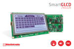
mikroBus Socket
The mikroBus socket allows a huge variety of mikroElektkronika
(www.mikroe.com) “click” add-on accessory boards to be
connected to the system. There are currently over 30 “click”
boards and counting, performing a vast variety of functions
such as communication, storage, audio, etc.
“ETH click” Ethernet board connected
“WiFi PLUS click” WiFi board connected
The mikroBus connections are explained in greater detail below:
AN
RST
CS
SCK
MISO
MOSI
+3.3V
GND
Analogue
Reset (different from the PIC’s reset)
SPI Chip Select
SPI* Serial Clock
SPI* Master-Out Slave-In (SDI on the PIC)
SPI* Master-In Slave-Out (SDO on the PIC)
3.3V Power Supply
Ground (0V Power Supply)
Pulse Width Modulation
Interrupt
UART (Serial) Receive
UART (Serial) Transmit
I²C** Serial Clock
I²C** Serial Data
5V Power Supply
Ground (0V Power Supply)
PWM
INT
RX
TX
SCL
SDA
+5V
GND
*Serial Peripheral Interface (communication interface)
**Inter-Integrated Circuit (communication interface)
www.dizzy.co.za
Revision 1.4
Page 11 of 14
microSD Socket
A microSD socket is included on the Breeze board. It is connected
to the standard SPI pins on the board, with the CS (chip select)
pin being connected to PortB.7 and the CD (card detect) pin being
connected to PortB.1. The card detect function is intended to be
used with the internal “weak pull-up” available on the PIC’s PortB.1
pin, however an external pull-up resistor (R3) can also be
connected if desired.
“ISP” Header
“ISP” connections are included on the Breeze board for maximum
compatibility with Arduino shields. “ISP” is the programming standard for
Atmel AVR ATmega microcontrollers, which the Arduino uses. Note that
soldering this header onto the board will block access to the microSD
socket.
PortC.2 LED
An LED is connected to PortC.2 of the PIC, and is very useful for debugging, or whatever
other purpose you may find for it. It can be easily disconnected if desired using jumper
JP24.
Offset PortB Socket
An offset PortB socket is provided on the Breeze board. This was done so that all
connections on the board are exposed in a 2.54mm (0.1in) grid format, making the board
compatible with various prototyping tools such as veroboard.
RTCC (Real-Time Calendar and Clock)
The PIC18F25J50 features a built-in RTCC (real-time calendar
and clock). The Breeze board has a facility for connecting a
32.768kHz crystal (X2) to the PIC’s PortC.0 (T1OSCO) and
PortC.1 (T1OSCI) pins, in order to run the RTCC. Two 12pF
capacitors are also connected between ground and these lines in
order to facilitate proper operation of the oscillator.
www.dizzy.co.za
Revision 1.4
Page 12 of 14
Drawing
For more information
please see the “Arduino
Template” file, available
from the Breeze page on
our website.
Microcontroller I/O Map
RA0
RA1
RA2
RA3
mB AN
mB RST
RA5
RA6
RA7
mB CS
(OSC2)
(OSC1)
RP0
RP1
RP2
RB0
RB1
RB2
RB3
RB4
RB5
RB6
RB7
mB INT
(SD CD1)
mB PWM
SCK/SCL
SDI/SDA
(Alt. SDO2)
(SD CS1 )
(PGC)
(PGD)
RP3
RP4
RP5
RP6
RP7
RP8
RP9
RP10
RC0
RC1
RC2
(T1OSCO)
(T1OSCI)
LED
RC4
RC5
RC6
RC7
USB DUSB D+
mB RX
SDO2
RP11
RP12
RP13
mB TX
RP17
RP18
1) Only applicable if an SD card is inserted. SD Card Detect switch is normally open –
R3 can be used to pull-up the input, if the PIC’s internal weak pull-up is not used.
2) JP17 can be used to switch SDO to RB6.
Links
The Breeze B board:
-
Is designed by Dizzy Enterprises (www.dizzy.co.za).
Is designed in the Proteus Design Suite (www.labcenter.com).
Features a mikroBus socket (www.mikroe.com).
Is compatible with (most shields), and draws inspiration from, the Arduino
(www.arduino.cc).
Draws inspiration from, the Amicus (www.myamicus.co.uk).
www.dizzy.co.za
Revision 1.4
Page 13 of 14
Disclaimer
This part says that you cannot sue us because we accept no responsibility for any
damages whatsoever that may be caused in connection with our products. We’ve
designed them the best we can, but please, use your common sense.
Errata
32.768kHz Crystal Pads
Due to an error in production the 32.768kHz crystal connection pads have been covered
in solder-resist and will not solder easily. This problem is however easily solvable by gently
scraping the solder-resist from the pads with a knife or similar sharp object. Note that the
colour of the pads once the solder-resist has been removed will be copper and not silver.
www.dizzy.co.za
Revision 1.4
Page 14 of 14