1
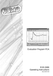
JUMO
dTRANS T02 LCD
programmable
transmitter
B 95.6522
Operating Instructions
10.00/00384955
Overview of operation
1 Type designation
JUMO dTRANS T02 LCD
(1) Basic version
956522
x
x
x
x
x
x
programmable transmitter
(2) Input (programmable)
888
factory-set (Pt100 DIN vl / 0 — 100°C)
999
configuration to customer specification1
(3) Output (proportional DC current - programmable)
888
factory-set (0 — 20mA)
999
configuration to customer specification
(0/4 — 20mA or 0/2 — 10V)
(4) Supply
22
20 — 53V AC/DC 48 — 63Hz
23
110 — 240V AC +10/-15% 48 — 63Hz
(1)
Order code
Order example
(2)
/
(3)
-
(4)
-
956522 / 888 - 888 - 23
1. For configuration to customer specification,
probe type and range have to be specified in plain text.
Standard accessory
- 1 Operating Instructions 95.6522
Accessories
- PC setup program, multilingual
- PC interface cable with TTL/RS232 converter and adapter
1
2 Installation
Connection diagram
Connection for
Supply
Analog inputs
Thermocouple
Resistance thermometer / potentiometer
in 2-wire circuit
RL ≤ 30Ω (RL = total lead resistance)
Resistance thermometer / potentiometer
in 3-wire circuit
Resistance thermometer / potentiometer
in 4-wire circuit
2
2 Installation
Resistance transmitter in
3-wire circuit
Voltage input < 1V
Voltage input ≥ 1V
Current input
Analog outputs
Voltage output
Current output
Digital outputs
Open-collector output 1
(see “Connection examples” on page 28)
Open-collector output 2
(see “Connection examples” on page 28)
3
2 Installation
Installation notes
!
The choice of cable, the installation and the electrical connections must conform to the requirements of VDE 0100 “Regulations for the installation of power circuits with nominal voltages
below 1000V”, or the appropriate local regulations.
!
The electrical connection, as well as work inside the unit, must
only be carried out by qualified personnel.
!
Ensure that the instrument is completely isolated from the supply before carrying out work where live components may be
touched.
!
A current limiting resistor (safety function) interrupts the supply
circuit in the transmitter in the event of a short-circuit. The external fusing of the supply voltage should not be rated above
1A (slow).
!
Avoid magnetic or electric fields, such as caused by transformers, mobile phones or electrostatic discharge in the vicinity of
the instrument1.
!
Do not install inductive loads (relays, solenoid valves etc.) close
to the instrument. Use RC networks, spark quenchers or freewheel diodes for interference suppression.
!
Route input, output and supply cables separately, and not parallel to each other. Run out and return cables next to each other
and twisted, if possible.
!
Probe cables must be twisted and shielded. Do not run them
close to current-carrying cables or components. Earth the
shielding at one end on the instrument.
!
Do not connect any additional loads to the supply terminals of
the instrument.
4
2 Installation
!
The instrument is not suitable for installation in areas with an
explosion hazard.
!
Any electrical connection which deviates from the connection
diagram may result in the destruction of the instrument.
!
In supply networks that are subject to interference (e.g. thyristor
controls), the instrument should be supplied via an isolating
transformer.
!
Supply fluctuations are only permissible within the specified
tolerances1.
1. see Data Sheet
Dimensions
5
3 Displays and controls
LCD display
interface for
PC setup program
buttons for operation
without significance,
for internal purposes
only
LEDs for operational status
P = Power LED
S = Status LED
Operational status at the
operating level
(normal operation)
Illumination/blink behavior
Limit comparator
1 inactive
2 inactive
Limit comparator
1 active
2 inactive
Limit comparator
1 inactive
2 active
Limit comparator
1 active
2 active
Overrange
6
3 Displays and controls
Operational status at the
parameter level
(programming mode)
Illumination/blink behavior
Limit for
limit comparator 1
Limit for
limit comparator 2
Fine calibration (zero)
Fine calibration (full scale)
Teach-in
(0 % value)
Differentiation of the operational states
- in the Operating level status, the
power LED is on permanently.
- in the Parameter level status, the
power LED blinks (equally on and off).
7
4 Functions and operation
You can operate and program the transmitter by using the q, d
and i buttons in conjunction with the LCD display and the blink cycles of the “Power” and “Status” LEDs, which have already been
described in Chapter 3 “Displays and controls”.
In use, three operating states can be distinguished:
- Operating level (normal operation)
- Parameter level (programming mode)
- Configuration level (programming mode)
Operating level
The transmitter is at the operating level 2 seconds after power-on,
or after leaving the parameter or configuration level.
Parameter level
From the operating level, you can access the parameter level by
pressing the q button (for at least 2 seconds). The following functions can be programmed at this level:
- Limit value for limit comparator 1
AL1
- Limit value for limit comparator 2
AL2
- Fine calibration (zero point - 0%)
OUTL
- Fine calibration (full scale - 100%)
OUTH
- Teach-in
OFFS
The parameter level is exited (quit)
- after editing the “Teach-in” parameter,
- if no button has been pressed for at least 20 seconds,
- or by pressing the button combination q + d.
The individual parameters can be altered, one after another. You
can step from one parameter to the next by pressing the q button.
8
4 Functions and operation
Configuration level
You can access the configuration level from the parameter level by
pressing the q button (for at least 2 seconds).
H
The parameters can only be modified when the parameter
OFFS is active in the display and the configuration level has
been started. If another parameter is active, you can only
read the current setting.
The following functions can be programmed at this level:
- Probe type
C111
- Linearization
C112
- Number of decimal places
C113
- Unit of measurement
C002
- Supply frequency and temperature compensation
C114
- Fixed value for temperature compensation
C115
- Measurement display
C116
- Function of the analog output
C211
- Signal on probe break/short-circuit
C212
- Function of the logic output 1
C221
- Signal on probe break/short-circuit
C222
- Lower switching differential (hysteresis)
C223
- Upper switching differential (hysteresis)
C224
- Function of the logic output 2
C231
- Signal on probe break/short-circuit
C232
- Lower switching differential (hysteresis)
C233
- Upper switching differential (hysteresis)
C234
9
4 Functions and operation
- Frequency at the range start
C235
- Frequency at the range end
C236
- Start value for scaling
SCL
- End value for scaling
SCH
- Filter time
DF
- Total resistance for resistance transmitter
R FE
- Simulation of measurement output
C001
The configuration level is exited (quit)
- after editing the last parameter,
- if no button has been pressed for at least 20 seconds,
- or by briefly pressing the button combination q + d.
The individual parameters can be altered, one after another. You
can step from one parameter to the next by pressing the q button.
10
4 Functions and operation
Incrementing values
When programming the parameters, the i button is used to increase a value (+).
Decrementing values
When programming the parameters, the d button is used to decrease a value (-).
Accepting values
If a setting has been altered, the q button has to be pressed to accept the alteration.
q has a twofold function:
- Acceptance of altered values
- Calling the next parameter
Value check
With the exception of the parameters OUTL, OUTH and OFFS, all
present values can be checked during programming with the aid of
the LCD display. A voltmeter can be used at the voltage output, as
an additional check.
H
H
If the parameter level is active, the analog output will not be
operated according to the input circuit connection when
programming the two limit values, but with the momentary
limit value.
Please note that the programming of the “Teach-in” parameter deviates from the standard operation.
See “Teach-in” on page 14.
11
4 Functions and operation
Setting the limit values (limit comparators)
You can alter the two limit values AL1 and AL2 by using the d and i
buttons. The momentary value will be produced via the output. The
value is accepted by pressing the q button.
The switching differential (hysteresis) can be set using the parameters C223 and C224 or C233 and C234.
Two functions are available for limit monitoring. With the help of the
parameter C221 or C231, you can decide which one to use.
Function lk7:
Function lk8:
Of course, all parameters can also be set using the PC setup program, which is available as an extra code.
12
4 Functions and operation
Fine calibration (zero point and full scale)
Fine calibration can be used to adjust the zero point and the slope
of the output signal. Here, too, the d and i buttons are available
for altering the appropriate value, and for accepting it by pressing
the q button.
The converted value is produced at the output. At zero point (OUTL),
this should correspond to the output signal 0%, at full scale (OUTH),
to the output signal 100%.
The formula for calculating the new (converted) value is:
output (converted) value = measurement (input) valuescaled x full scale + zero point
13
4 Functions and operation
Teach-in
The “Teach-in” parameter serves to define the 0% value.
During programming, the zero point is produced at the output (e.g.
4mA). This value is accepted by pressing the d or i button and
executed with q. After a time-out without acceptance, the old value
will be available again.
Example:
The position of a valve is detected by a potentiometer. The potentiometer covers the range 50 to 150Ω, with 50Ω corresponding to the
valve closed. The range is programmed as follows:
- Potentiometer 50 — 150 Ω
- Output 0 — 20mA
The following is assumed:
However, because of mechanical tolerances, the potentiometer position with the valve closed is 52Ω, which results in an output current of 0.4mA. Thanks to the “Teach-in” function, this error can be
eliminated as described below:
- Close valve
- Call the parameter level and select OFFS
(0.4mA should then be present at the output).
- Press the d or i button – the output must now
change to 0mA.
- Confirm alteration by pressing q.
- Exit the parameter level (either after a time-out of 20sec or by
simultaneously pressing q + d.
14
5 Configuration and parameter tables
You can record your settings in the configuration and parameter tables below, in the position (column) marked with
. The factory
settings are shown on a gray background ( ).
Parameters at the parameter level
Para- Explanation
meter
Al1 Limit value of
limit comparator 1
AL 2 Limit value of
limit comparator 2
OUTL Fine calibration 0%
(zero)
OTUH Fine calibration 100%
(full scale)
OFFS Teach-in
Value range factory
X
setting
0
-1999 to
+9999 digit
-1999 to
0
+9999 digit
see “Fine calibration (zero point
and full scale)” on page 13
see “Fine calibration (zero point
and full scale)” on page 13
see “Teach-in” on page 14
Parameters at the configuration level
Measurement input
C111 Transducer
0
1
2
3
4
5
6
7
8
9
10
X
Resistance thermometer in 3-wire circuit
Resistance thermometer in 4-wire circuit
Resistance thermometer in 2-wire circuit
Thermocouple
Voltage up to 1000mV
Voltage up to 10V
Current
Resistance transmitter
Potentiometer 3-wire circuit
Potentiometer 4-wire circuit
Potentiometer 2-wire circuit
15
5 Configuration and parameter tables
C112 Linearization
0
1
2
3
4
5
6
7
8
9
10
11
12
13
14
15
16
17
18
19
20
X
linear
customized
Pt 100 DIN
Pt 500 DIN
Pt 1000 DIN
Pt 100 JIS
Ni 100
Ni 500
Ni 1000
Type L
Type J
Type U
Type T
Type K
Type E
Type N
Type S
Type R
Type B
Type D
Type C
C113 Number of decimal places
0
1
2
no decimal place
1 decimal place
2 decimal places
16
X
5 Configuration and parameter tables
C002 Unit of measurement
0
1
2
3
4
5
6
7
8
9
10
11
12
13
14
15
16
17
18
19
20
21
22
23
24
25
26
27
28
X
(only effective if parameter C116 = 2
see page 21
Unit
LCD display
°C
°C
°F
°F
K
K
bar
mbar
Pa
kPa
s
ms
min
h
d
100ms
ml/s
ml/min
l/s
l/min
l/h
m³/s
m³/min
m³/h
1/s
1/min
1/h
Hz
kHz
MHz
lx
BAR
mBAR
PA
KPA
SEC
mSEC
min
H
d
100mS
mL/S
mL/mn
L/SEC
L/min
L/H
m3/S
m3/mn
m3/H
1/SEC
1/min
1/H
HZ
KHZ
MHZ
LX
17
5 Configuration and parameter tables
C002 Unit of measurement
29
30
31
32
33
34
35
36
37
38
39
40
41
42
43
44
45
46
47
48
49
50
51
52
53
54
55
56
57
X
(only effective if parameter C116 = 2
see page 21
Unit
LCD display
mlx
mLX
klx
KLX
cd
cd
mcd
mcd
kcd
Kcd
µm
µm
mm
mm
cm
cm
m
m
km
Km
%
%
‰
‰
ppm
PPM
ppb
PPB
µg
µG
mg
mG
g
G
kg
KG
t
T
µW
µW
mW
mW
W
W
kW
KW
MW
MW
mVA
mVA
VA
VA
kVA
KVA
mVAs
mVAS
VAs
VAS
18
5 Configuration and parameter tables
C002 Unit of measurement
58
59
60
61
62
63
64
65
66
67
68
69
70
71
72
73
74
75
76
77
78
79
80
81
82
83
84
85
86
X
(only effective if parameter C116 = 2
see page 21
Unit
LCD display
kVAs
KVAS
J
J
µJ
µJ
mJ
mJ
kJ
KJ
Ws
WS
kWh
KWH
pH
PH
mΩ
mOHM
Ω
OHM
kΩ
KOHM
MΩ
MOHM
mm/s
mm/S
mm/h
mm/H
m/s
m/SEC
m/min
m/MIN
km/h
Km/H
%/s
%/S
m/s²
m/S2
G
G
µl
µL
ml
mL
l
L
hl
HL
m³
M3
µV
µV
mV
mV
V
V
kV
KV
19
5 Configuration and parameter tables
C002 Unit of measurement
87
88
89
90
91
92
93
94
95
96
97
98
99
100
101
102
103
104
105
106
107
108
109
110
111
112
113
114
115
X
(only effective if parameter C116 = 2
see page 21
Unit
LCD display
µA
µA
mA
mA
A
A
kA
KA
S
S
mS
mS
µS
µS
nH
nH
µH
µH
mH
mH
H
H
pF
PF
nF
nF
µF
µF
mF
mF
F
F
mm²
mm2
cm²
cm2
m²
m2
km²
Km2
kg/l
KG/L
g/l
G/L
N
N
mN
mN
kN
KN
Nm
Nm
Nmm
Nmm
Nkm
NKm
µV/K
µV/K
20
5 Configuration and parameter tables
C114 Supply frequency/temperature compensation X
0
50Hz / internal temperature compensation
1
50Hz / fixed temperature compensation
2
60Hz / internal temperature compensation
3
60Hz / fixed temperature compensation
Para- Explanation
meter
C115 value with fixed
temperature
compensation
Value range factory
setting
0
0 — 100°C
C116 Measurement display
0
1
2
X
X
percent
as output signal (mA or V)
in configurable unit
(see parameter C002 page 17)
Analog output
C211 Function of the analog output
X
0
0 — 20mA
1
4 — 20mA
2
0 — 10V
3
2 — 10V
The limits can be inverted by swapping the two parameters
SCL and SCH.
C212 Signal of output on
probe break/short-circuit
0
positive (22mA or 11V - according to C211)
1
negative (0mA or 0V - according to C211)
21
X
5 Configuration and parameter tables
Logic output 1
C221 Function of the logic output 1
X
0
1
2
3
no function
lk7
lk8
fault output
You will find additional information on lk7 and lk8 in
“Setting the limit values (limit comparators)” on page 12.
C222 Signal of logic output 1 on
probe break/short-circuit
0
active
1
inactive
2
unchanged
X
Value range factory
Para- Explanation
setting
meter
100
C223 Lower switching
0 — 250
differential (hysteresis)
The value range corresponds to 0 — 2.5%.
X
Value range factory
Para- Explanation
setting
meter
100
C224 Upper switching
0 — 250
differential (hysteresis)
The value range corresponds to 0 — 2.5%.
X
22
5 Configuration and parameter tables
Logic output 2
C231 Function of the logic output 2
X
0
1
2
3
no function
lk7
lk8
Frequency output
You will find additional information on lk7 and lk8 in
“Setting the limit values (limit comparators)” on page 12.
C232 Signal of the logic output 2 on
probe break/short-circuit
0
active or frequency C236
1
inactive or frequency C235
2
unchanged
X
Value range factory
Para- Explanation
settting
meter
100
C233 Lower switching
0 — 250
differential (hysteresis)
The value range corresponds to 0 — 2.5%.
X
Value range factory
Para- Explanation
setting
meter
100
C234 Upper switching
0 — 250
differential (hysteresis)
The value range corresponds to 0 — 2.5%.
X
Para- Explanation
meter
C235 Frequency at
range start
X
Value range factory
setting
10
10 —
1000Hz
23
5 Configuration and parameter tables
Para- Explanation
meter
C236 Frequency at
range end
Value range factory
setting
1000
10 —
1000Hz
X
Value range factory
setting
0
-1999 to
+9999 digit
-1999 to
100
+9999 digit
0.0 —
0.6
100.0sec
0 — 4000Ω
1000
X
Additional parameters
Para- Explanation
meter
SCL Scaling start value
SCh
Scaling end value
DF
Filter time constant
R FE
Total resistance for
resistance transmitters
C001 Simulation of
measurement output
0 — 110%
(110 =
switched off)
24
110
6 Tips ...
... on operation within the parameter and configuration
levels
H
Pressing the q button to confirm a value entry requires that
a value has previously been modified.
If this is not the case, the confirmation will be interpreted as
a call of the next parameter.
H
If, after an accidental alteration, the value is not to be accepted, just wait for the time-out of 20sec. Afterwards, the
instrument will automatically jump back to normal operation, without accepting the alteration.
H
Please check that all entered values are correct. The transmitter itself does not check value ranges.
H
Please note that the programming of the “Teach-in” parameter differs from the standard operation.
see “Teach-in” on page 14.
H
In order to be able to modify the parameters at the configuration level, the configuration level has to be called up when
the display shows the parameter OFFS. If this is not the case,
you can read the parameters, but you cannot modify them.
25
6 Tips ...
... of a more general nature
H
If none of the parameters can be modified, then you may
have locked the operation on the instrument through the
setup program. Please check the setting using the setup
program.
Instrument operation
Inhibits:
Operating level:
Parameter level:
Configuration level:
none
none
none
The instrument settings can only be modified when “Operating level”, “Parameter level” and “Configuration level” are
set to “none”.
H
A
Both outputs (current and voltage) are always available at
the same time. However, the output that has not been activated only has an accuracy of approx. ± 2% of full scale.
The frequency output will not be operated as long as the
setup interface is active.
:
26
7 PC setup program
The PC setup program, which is available as an extra, can be used
to modify all parameters of the transmitter (including the custom linearization) with ease. Through the setup interface, the transmitter
and the PC are linked via the “PC interface with TTL/RS232 converter and adapter”.
Configurable parameters
- TAG number (10 characters)
- analog input (sensor type)
- connection circuit (2-/3-/4-wire circuit)
- external or constant cold junction
- custom linearization
- range limits (start and end)
- output signal current/voltage/frequency rising/falling
- digital filter
- response to probe break/short-circuit
- recalibration/fine calibration
- instrument calibration
- limit value/differential of the limit comparators
- file-info text
Additional benefits of the PC setup program
- manage several settings
- one setting for several transmitters
- print out setting for documentation
- operation can be switched to GMA standard
A
The frequency output will not be operated as long as the
setup interface is activated.
27
8 Connection examples
Example 1
Connecting a PLC to the open-collector output
Calculation example for RA (working resistance)
In this example, the following typical PLC characteristics are assumed:
- for signal “1”:
13 — 30V
- for signal “0”:
-3 to +5V
- input current for signal “1”:
7mA
An assumed input voltage of 18V/7mA for signal “1” results in the
following calculation:
24V - 18V
R A 85.14 Ω
7mA
Result: A resistance of 820 ⍀ will be selected.
28
8 Connection examples
Example 2
Connecting a relay to the open-collector output
29
8 Connection examples
30
M. K. JUCHHEIM GmbH & Co
JUMO Instrument Co. Ltd.
Street address:
Moltkestraße 13 - 31
36039 Fulda, Germany
Delivery address:
Mackenrodtstraße 14
36039 Fulda, Germany
Postal address:
36035 Fulda, Germany
Phone: +49 (0) 661 60 03-0
Fax:
+49 (0) 661 60 03-5 00
E-Mail: [email protected]
Internet: www.jumo.de
JUMO House
Temple Bank, Riverway
Harlow, Essex CM20 2TT, UK
JUMO PROCESS CONTROL INC.
735 Fox Chase,
Coatesville, PA 19320, USA
Phone: 610-380-8002
1-800-554-JUMO
Fax:
610-380-8009
Phone: +44 (0) 1279 63 55 33
E-Mail: [email protected]
Fax:
+44 (0) 1279 63 52 62
E-Mail: [email protected] Internet: www.JumoUSA.com