1
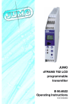
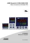
Electronic Microstat
B 70.1060.0
Operating Instructions
01.03/00412150
Overview of operation
Alternating display
P > 3sec
Temperature display
30sec time-out
(simultaneously)
or P +
P or 30sec time-out
P
Enter code
increase
increase
decrease
decrease
P
P
Operating level
Parameter level
Enabling level
Parameters that have been
selected at the enabling level.
Factory-set parameters can be
altered here.
Define parameters which can be
displayed or edited at the
operating level.
Alternating display
Alternating display
Alternating display
increase
increase
decrease
decrease
P
P P
additional parameters …
editable
P P
additional parameters
show
do not
enable
additional parameters
xxx
… from the
enabling level
60sec time-out or P +
(simultaneously)
last parameter
Contents
1
Instrument identification . . . . . . . . . . . . . . . . . . . . . . . . . . . . . . . . . . . . . . . . . . . . . . . . . . . 4
2
Mounting . . . . . . . . . . . . . . . . . . . . . . . . . . . . . . . . . . . . . . . . . . . . . . . . . . . . . . . . . . . . . . . . 5
3 Electrical connection . . . . . . . . . . . . . . . . . . . . . . . . . . . . . . . . . . . . . . . . . . . . . . . . . . . . . . 6
3.1 Installation notes . . . . . . . . . . . . . . . . . . . . . . . . . . . . . . . . . . . . . . . . . . . . . . . . . . . . . . . . . . 6
3.2 Connection diagram . . . . . . . . . . . . . . . . . . . . . . . . . . . . . . . . . . . . . . . . . . . . . . . . . . . . . . . . 7
4 Commissioning the instrument . . . . . . . . . . . . . . . . . . . . . . . . . . . . . . . . . . . . . . . . . . . . . . 8
4.1 Displays and controls . . . . . . . . . . . . . . . . . . . . . . . . . . . . . . . . . . . . . . . . . . . . . . . . . . . . . . . 8
4.2 Setting the instrument functions (parameter level) . . . . . . . . . . . . . . . . . . . . . . . . . . . . . . . . . 9
4.3 Allocating user rights (enabling level) . . . . . . . . . . . . . . . . . . . . . . . . . . . . . . . . . . . . . . . . . . 16
5
Operation . . . . . . . . . . . . . . . . . . . . . . . . . . . . . . . . . . . . . . . . . . . . . . . . . . . . . . . . . . . . . . 17
6
Technical data . . . . . . . . . . . . . . . . . . . . . . . . . . . . . . . . . . . . . . . . . . . . . . . . . . . . . . . . . . 18
7
Alarm messages . . . . . . . . . . . . . . . . . . . . . . . . . . . . . . . . . . . . . . . . . . . . . . . . . . . . . . . . . 20
1
Instrument identification
The nameplate is affixed to the bottom of the instrument. The supply that is connected must correspond to
the voltage specified on the nameplate.
All necessary settings are described in these
Operating Instructions. If any difficulties should
still arise during start-up, you are asked not to
carry out any unauthorized manipulation on the
unit. You could endanger your rights under the
instrument warranty! Please contact the nearest
subsidiary or the head office.
701060/888-02
(1)
701060
(2) (3)
(1) Basic version
JUMO ecoTRON M
(2) Measurement input
factory setting,
configurable
999
customized configuration
003
Pt100 in 2-wire circuit
005
Pt1000 in 2-wire circuit
606
KTY2X-6
(3) Supply
02
230V AC +10/-15% 48 — 63Hz
05
115V AC +10/-15% 48 — 63Hz
18
24V DC +15/-15%
20
12V DC +15/-15%
888
Please read these operating instructions carefully before commissioning the instrument. Keep
the manual in a place that is accessible to all users at all times. Please assist us to improve
these operating instructions, where necessary.
1 Instrument identification
H
Order
code
factory setting
Delivery package
1 seal
1 mounting frame
1 Operating Instructions 70.1060
4
Mounting
Mounting frame
76
°C
K1
36
55
56
28
2
5
0
Snap-in lugs
Bezel size:
76mm x 36 mm
+2.5
≤ 75
Panel cut-out:
Side-by-side mounting
up to 40°C max.
ambient temperature
Spring clip
+1
69-0 mm x 28.5 -0 mm
2 Mounting
68.5
10mm horizontal,
15mm vertical
h Pull off mounting frame from instrument.
h Insert the instrument from the front into the panel cut-out and make sure that the bezel seal is seated correctly.
h From the back, push mounting frame onto the housing
until the spring clips are under tension and the snap-in lugs have engaged at top and bottom.
5
3
Electrical connection
3.1 Installation notes
a
a
a
a
a
a
a
The electromagnetic compatibility (EMC) conforms to the standards and regulations listed under Technical
Data.
The instrument is not suitable for installation in areas with an explosion hazard.
Apart from faulty installation, incorrect settings on the thermostat (setpoint, data of parameter and
configuration levels) may also affect the proper functioning of controlled processes or lead to damage.
Provision should therefore always be made for safety devices independent of the thermostat, e. g. overpressure valves or temperature limiters/monitors. Adjustments must be restricted to specialist personnel (lock
parameters for operation). Please observe the corresponding safety regulations in this matter. Unfavorable
parameter adjustments may lead to unstable control. The resulting process value should therefore be monitored for its stability and knowledge about the process should be obtained.
The load circuit must be fused for the maximum relay current in order to prevent welding of the output relay
contacts in the event of a short circuit.
Do not connect any additional loads to the supply terminals of the instrument.
3 Electrical connection
a
a
The choice of cable, the installation and the electrical connection must conform to the requirements of
VDE 0100 “Regulations on the Installation of Power Circuits with nominal voltages below 1000 V” or the
appropriate local regulations.
The electrical connection must only be carried out by qualified personnel.
The external fuse of the supply should not be rated below 1A, depending on the conductor cross-section.
If contact with live components is possible while working on the instrument, the Microstat must be disconnected on both poles from the supply.
Supply
Measurement input and supply
AC short-circuit-proof
electrically isolated from each other
DC not short-circuit-proof
not electrically isolated from each other
6
3.2 Connection diagram
Output
10A 250V
6
7
N
L1
AC
ⵒ
230V
ϑ
Pt100/1000
KTY2X-6
AC
ⵒ
115V
DC
=
24V
DC
=
–
3
Measurement input
+
2
–
1
+
V
The electrical connection
must only be carried out by
qualified personnel!
Supply voltage
as per
nameplate
Ö
P
3 Electrical connection
S
12V
Supply
7
4
Commissioning the instrument
4.1 Displays and controls
3-digit, 9-segment display, 13 mm high, with
symbols for temperature unit, h, min, s, defrosting
and heating, red background lighting.
LED K1
LED K1 comes on when relay is energized.
LED K1 goes out when relay is de-energized.
Keys
Temperature display
for start-stop
during heating and cooling operation
programming
increase value
select operational status at enabling level
decrease value
select operational status at enabling level
h When connected to the supply, all segments light up twice as a test (segment test).
When everything is connected correctly on the instrument, the present temperature is shown (temperature display)
If an alarm message appears, see Chapter 7 “Alarm messages”.
4 Commissioning the instrument
LC display
The relay operates according the controller type that was set,
see Chapter 4.2 “Setting the instrument functions (parameter level)”.
8
4.2 Setting the instrument functions (parameter level)
Time-out:
If no key is pressed for 60 sec, the instrument automatically switches back to the temperature display,
see Overview of operation on the first inside page.
The instrument functions and values are set at the parameter level.
h Press the
key for 3 seconds and
will appear alternately.
h Set code 72 for accessing the parameter level by pressing the
and
The longer the key is pressed the faster the value changes.
h Acknowledge with
,
parameter name and value appear alternately, e.g.
.
and
keys.
h Set value within the specified range using the
h Acknowledge settings with .
h Set next parameter, see Overview of Operation on the front inside page.
keys.
4 Commissioning the instrument
H
9
Controller
Value range
from...factory-set...to
Parameter Meaning
SP.L ... 0.0 ... SP.H
Hysteresis
0.2 ... 1.0 ... 99.9 °C/°F
Cooling
T/°C
69 °C
9
SP = 8 °C
Heating
T/°C
SP = 70 °C
HYS
HYS
t
t
Relay
energized
Relay
energized
de-energized
de-energized
t
t
Low setpoint limit
The lower limit for setpoint selection.
-350 ... -50 ... 999°C/°F
High setpoint limit
The upper limit for setpoint selection.
-350 ... 500 ... 999°C/°F
Controller type
: cooling controller
: heating controller
Switch-on delay after power ON
For staggered switch-on of several equipment units.
4 Commissioning the instrument
Setpoint
The target temperature
0 ... 60min
10
Value range
from...factory-set...to
Parameter Meaning
Minimum
OFF time
Timer
,1... 999 min
Defrosting/heating time
Defrosting time for cooling contr. (Col), heating time for heating contr. (Hot).
Cooling
controller
Cyclic
cooling with
defrosting
ti.0 ≥1
Defrosting repeat cycle
t.CY
ti.0
t.CY - ti.0
If required:
Stop cooling,
start defrosting
>1 sec
with key
Cooling
Stop defrosting,
start cooling
>1 sec
with key
Cooling
tCY ≥1
One-off
defrosting
Start one-off defrosting
>1 sec
with key
Cooling
The 6 dots indicate:
no time limit.
This is shown instead of
the value “0”.
factory-set:
t
ti.0 ≥1
tCY =
Cooling
Setting for one-off defrosting:
Defrosting repeat cycle
Cooling
set ti.0 to
* First
Then set tCY to
* Now set new defrosting time ti.0
*
only with the cooling controller setting (Col)
t
4 Commissioning the instrument
Here you can set the minimum time for which the equip- 0 ... 999 s
ment unit, for example, has to remain switched on or off.
These values depend on the heating or cooling unit being
0 ... 999 s
used (observe manufacturer’s specification).
In the event of a probe error, the relay (as set in parameter S.Er) is operated immediately.
Minimum
ON time
0 ... 24 ... 999 h
11
Value range
from...factory-set...to
Parameter Meaning
Currently remaining running time
Heating controller
Heating, no
time limit
ti.0 =
Heating, with
time limit
ti.0 ≥1
Stop heating
>1 sec
with key
Heating
Heating time ti.0
Heating
Heating OFF
Heating OFF
Start heating
>1 sec
with key
Heating
Start heating
>1 sec
with key
t. i cannot be edited
Heating
Start heating
>1 sec
with key
,
t
Heating
t
The starting action after power ON is set via parameter P.On
0 ... 999h ... 9.9t h
Service interval
The time period after which the equipment unit has to be serviced is set
here. The active relay time is taken into account. (t = thousand)
Current service counter for equipment unit connected
This shows how much time has elapsed since the last service.
On reaching the interval
, an alarm message is generated.
If the counter is reset after a service, the alarm message disappears.
0 ... 999h ... 9.9t h
Display of the total operating hours
Active time of relay for maintenance of heating or cooling units.
0 ... 999h ... 9.9t h
4 Commissioning the instrument
for example for cooling/heating operation etc.
999h ... 2h,
120min ... 2min,
120s ... 0s,
With setting
12
Value range
from...factory-set...to
Parameter Meaning
0, 1
Response after power ON
0, 1
Enabling the start-stop key
0: inhibited
1: enabled
Cooling contrl. Heating contrl.
0
Defrosting
Heating OFF
1
Cooling
Heating
0, 1
Alarms
-350 ... -200 ... 999°C/°F
Low alarm limit temperature 1
If the process value falls below this limit during heating or cooling, the alarm
message
is output to the display, see Chapter 7 “Alarm messages”.
-350 ... 500 ... 999°C/°F
High alarm limit temperature 1
If the process value goes above this limit during heating or cooling, the
alarm message
is output to the display, see Chapter 7 “Alarm messages“.
Alarm suppression time1
0 ... 60 min
The alarm
or
is not displayed until this time has elapsed. If
the alarm is present for longer than
, then it will be displayed.
1.) During defrosting
4 Commissioning the instrument
Temperature display during defrosting
freeze temperature value during defrosting: 0
update temperature value continuously: 1
and also during heating OFF (symbol for heating has gone out), alarm monitoring is inactive.
13
Parameter Meaning
Value range
from...factory-set...to
0, 1
Transducer
Pt 100: P.1h
Pt 1000: P.1t
KTY2X-6: PtC
Input
Transducer connected in 2-wire circuit
Temperature offset
Temperature offset in °C or °F
-99.9 ... 0.0 ... 99.9 °C/°F
0.0 ... 0.0 ... 99.9 Ω
Lead compensation resistance
This value is used to compensate the resistance of the probe cable and depends on the cable length.
For optimum temperature measurement, the resistance value of the probe
cable (with shorted probe) has to be entered here.
A
If the total resistance at the measurement input (transducer
resistance + value selected for OF.r) exceeds 320 Ω with Pt100, or
3200 Ω with Pt1000/KTY2x-6, a measurement error will result !
Unit
for the temperature displayed
A
°C or °F
4 Commissioning the instrument
Response to over/underrange
0: relay immediately de-energized
1: relay immediately energized
Only the measured value is converted accordingly when changing
over to °F. All other temperature variables e.g. SP will retain their
values.
14
Parameter Meaning
Value range
from...factory-set...to
H
Return to the first parameter SP at the parameter level by pressing
> 3 seconds.
4 Commissioning the instrument
0.0 ... 0.8 ... 99.9 s
Filter time constant
For adapting the digital input filter (0.0 seconds = filter OFF).
With a signal step, 63% of the change is registered after the filter time constant has elapsed.
Values between 0.1 and 0.7 are interpreted as 0.8 (sampling time).
If the filter time constant is too long:
- high damping of interference signals
- slow reaction of the process value display to process value changes
15
4.3 Allocating user rights (enabling level)
The setting at the enabling level defines user rights which determine whether a parameter is shown at the operating
level, can be edited, or is not shown at all.
key for 3 seconds and
appears.
h Set code 82 for accessing the enabling level by pressing the
and
keys.
h Acknowledge with
Parameter and User rights blink alternately e.g.
h Use the
and
keys to set user rights to
User rights
,
or
Display
factory-set
Parameter is editable at the operating level
Parameter appears at the operating level
-
Parameter does not appear at the operating level
all other parameters
h Acknowledge setting with .
h Set next parameter, see Overview of operation on the front inside page.
4 Commissioning the instrument
h Press the
16
5
Operation
Alter target temperature and further parameters
Temperature display
Cooling controller
Defrosting
Cooling
Target temperature
1 sec
Heating
Heating OFF
Display software version
+
P
P
P
5 Operation
P
Heating controller
or time-out (after approx. 30 sec)
1 sec
(simultaneously)
(Example)
Display further parameters
(according to user rights selected
at the enabling level)
17
6
Technical data
Measurement input
Range
Accuracy
Overrange/underrange
-200 to +500°C
0.1%
is recognized
-200 to +500°C
0.1%
is recognized
-50 to 150 °C
1%
is recognized
≤ 100 ppm per °C of range
250 msec, resolution > 14bit
1st order digital filter; filter constant adjustable from 0 — 99.9sec
Lead compensation1
adjustable via the parameter Lead compensation resistance
Temperature offset1
adjustable via the parameter Temperature offset
Features
temperature display °C, can be changed over to °F
1. see Chapter 4.2 “Setting the instrument functions” (parameter level)
Environmental influences
Ambient temperature range
Storage temperature range
Climatic conditions
Care of the front panel
6 Technical data
Designation
Pt100 EN 60 751
Pt1000 EN 60 751
KTY2X-6
Temperature error
Sampling time
Input filter
0 to +55°C, for side-by-side mounting: 0 to +40°C
-40 to +70°C
≤ 75% rel. humidity, no condensation
The front panel can be cleaned with all the usual rinsing and cleaning agents.
Do not use solvents such as methylated spirit, white spirit, P1 or xylene.
18
Output
Relay (changeover contact)
150,000 operations at 10A 250V AC 50Hz resistive load
800,000 operations at 3A 250V AC 50Hz resistive load
Supply
Supply voltage
Power consumption
230V AC +10/-15%,
115V AC +10/-15%,
< 3VA
24V DC +15/-15%
12V DC +15/-15%
Material
Mounting
Operating position
Weight
Protection
Flammability class
polycarbonate
in panel cut-out with bezel seal
unrestricted
approx. 160g
front IP65, rear IP20
UL 94 VO
Electrical data
Data backup
Connection
Electromagnetic compatibility
- interference emission
- immunity to interference
Operating conditions
Electrical safety
Accuracy of timer
EEPROM
screw terminals for wire cross-sections up to 4 mm2 solid wire
and up to 2.5 mm2 stranded wire
EN 61 326
Class B
to industrial requirements
The instrument is designed for flush panel mounting.
EN 61 010, Part 1, overvoltage category III, pollution degree 2
2.5 min per month, temperature error 10ppm per 10°C
6 Technical data
Housing
19
7
Alarm messages
The following alarm messages can be shown in the temperature display:
Error message
Cause
Elimination
Display overrun
The measured value is too large and is
outside the range.
-
Check sensor and connecting cable for
damage and short circuit
Display underrun
The measured value is too small and is v Chapter 4 “Commissioning the instrument”
outside the range.
These messages are only output to
the temperature display.
H
ProcVal
ProcVal
ProcVal
ProcVal
Service interval has elapsed
The time that was set for servicing a
heating or cooling unit has elapsed.
Time for switch-on delay after
power ON has elapsed.
With display over/underrun, the
switch-on delay becomes ineffective.
Value has fallen below the low alarm
limit temperature
Value has gone above the high alarm
limit temperature
h Carry out service
manually to 0 at the parameh Reset
ter level
v Chapter 4 “Commissioning the instrument”
h Cancel switch-on delay
with
+
7 Alarm messages
Check whether the correct sensor has been
set or connected
h Depending on the selected controller type,
check whether the heating or cooling unit
functions faultlessly.
h Check whether the relay fuse installed is still
in good working order.
The alarm disappears when the temperature goes above
or below the AL limits by the amount of the hysteresis.
20
M. K. JUCHHEIM GmbH & Co
JUMO Instrument Co. Ltd.
JUMO PROCESS CONTROL INC.
Street adress:
Moltkestraße 13 - 31
36039 Fulda, Germany
Delivery address:
Mackenrodtstraße 14
36039 Fulda, Germany
Postal address:
36035 Fulda, Germany
Phone:
+49 661 6003-0
Fax:
+49 661 6003-607
E-mail:
[email protected]
Internet:
www.jumo.net
JUMO House
Temple Bank, Riverway
Harlow, Essex CM20 2TT, UK
Phone: +44 1279 635533
Fax:
+44 1279 635262
E-mail: [email protected]
Internet: www.jumo.co.uk
885 Fox Chase, Suite 103
Coatesville PA 19320, USA
Phone:
610-380-8002
1-800-554-JUMO
Fax:
610-380-8009
E-mail:
[email protected]
Internet:
www.JumoUSA.com