1
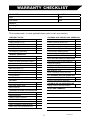
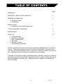
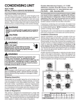
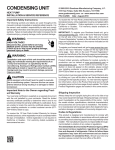
AIR
INCORPORATED
OPERATING AND SERVICE MANUAL
For technical service or repair,
FIRST CALL - INSTALLING CONTRACTOR:
SECOND CALL: Titan Representative
XXX-YYY-ZZZZ
FINAL CALL: Titan Air Inc.
715-597-2050
Please have serial number available when calling
WARRANTY
24 MONTH WARRANTY
The Manufacturer hereby warrants its products against defects in material and
workmanship for a period of (24) twenty four months from date of shipment.
Warranty sheet is due back within (30) thirty days of start-up for 24 month warranty
to be effective. After (30) thirty days, and up until (60) sixty days, a (12) twelve month
warranty will be observed. All warranties are null and void if warranty sheet is not
received within (60) sixty days from start-up. NO EXCEPTIONS WILL BE MADE.
The Manufacturer reserves the right at The Manufacturer’s option, to replace or
repair free of charge, any part proven by The Manufacturer to be defective. Prompt
notification of defective part must be given to The Manufacturer and defective part must
be returned freight prepaid within (30) days of notificaion.
WARRANTY INCLUDES ONLY PARTS SUPPLIED BY THE MANUFACTURER
INCIDENTAL COSTS AND LABOR CHARGES SHALL BE THE RESPONSIBILITY OF
OTHERS. This warranty does not cover fuses, belts, filters or water damaged parts.
This warranty is void in event the product is improperly installed and/or operated
under conditions other than normal published ratings, improperly maintained, misused or
not in compliance with applicable codes: or not in accordance with The
Manufacturer’soperating instructions.
This warranty is void if attempts to correct or repair any alleged defective part or
parts are made by unauthorized personnel without The Manufacturer’s written approval.
In no event shall The Manufacturer be held liable for any damage, incidental or
consequential, arising from the installation, performance or operation of the product.
This warranty supersedes, voids and/or is in lieu of any other verbal or written
understanding which may not be in total accordance with this expressed warranty.
Warranty parts must be returned to The Manufacturer within 60 days to receive
credit.
PURPOSE / APPLICABILITY
This manual is intended to provide general installation, operating, and service
information on a specific type of Air Handler.
A packet of reference materials for a specific unit (tracked by its Serial Number) is
typically included with this Operating and Service Manual. The reference materials
include Unit Specifications, Parts Lists, Gas Train and Burner Specifications, Electrical
Schematic, and a Sequence of Operation. Review the reference materials for a specific
unit and note any optional equipment or controls which are not specifically addressed in
this manual prior to attempting start-up or service work.
1
TAH OSM Rev 5
WARRANTY CHECKLIST
Model: TAH-
Serial No.:
Rep.:
Date:
Job Name:
Date:
Address:
Installing Contractor:
Signature
Fill in numbers and / or check applicable items (refer to start up procedure).
PRESTART STATUS
HYDRONIC & DX COOLING COIL OPERATION
Supply Voltage (L1-L2)
Supply Voltage (L1-L3)
Supply Voltage (L2-L3)
Control Voltage
Motor FLA
Coil Capacity (if applicable)
Unit Installed Level
Freeze Protection (Water Coil)
Cooling Control Functional
Room / Discharge Control Set Point
Drain Pan Properly Piped & Trapped
Full Flow EDB / EWB (optional)
Full Flow LDB / LWB (optional)
Full Flow EWT / Suction Temp. (opt.)
GENERAL OPERATION
Service Switches
Remote Switching / Sequencing
Damper Actuator (End Switch if Applic.)
Starter / Overload Combination
Blower Rotation Direction
ELECTRIC HEATING COIL OPERATION
Power Source Short Circuit Protection
Supply Wire Gauge
Supply Wire Temp. Rating
Heating Control Functional
Max. Heat EAT / LAT
Room / Discharge Control Set Point
Motor Amp Draw (L1)
Motor Amp Draw (L2)
Motor Amp Draw (L3)
Air Flow Switch
Low Temperature Safety (Freezestat)
FA / RA MIXING SECTION OPERATION
Dampers Drive Properly on Shutdown
Damper Controlled Per Sequence
SETTINGS
Low Temp. Safety Time
Low Temp. Safety Temp.
Motor Overload
VARIABLE AIR VOLUME OPERATION
Supply Volume Controlled Properly
NOTES AND COMMENTS
HYDRONIC HEATING COIL OPERATION
Unit Installed Level
Freeze Protection
Heating Control Functional
Full Flow EAT/LAT
Full Flow EWT/LWT or Steam PSIG
Room / Discharge Control Set Point
Steam Trap / Vacuum Breaker Func.
2
TAH OSM Rev 5
TABLE OF CONTENTS
WARRANTY
Page
1
WARRANTY VERIFICATION CHECKLIST
2
GENERAL INFORMATION
¾ Equipment Arrival
¾ Components
4
INSTALLATION
¾ Installation and Field Wiring Overview
6
TYPICAL ASSEMBLY DRAWINGS
9
MAINTENANCE
11
START-UP
¾ Unit Specification
¾ Sequence of Operation
¾ Parts / Legend Sheet
¾ Schematic
¾ Start-Up Procedure
¾ Troubleshooting (optional)
14
Note that operating and service manuals are occasionally requested prior to production
of a unit. These manuals will be marked “Pre-Production Release” on the front cover.
The final copy of the operating and service manual for a specific unit will be sent with the
unit. Additional copies of the manual for a specific unit are available.
A detailed unit specification sheet, parts/legend sheet, schematic, sequence of operation
and start-up procedure are provided in the start-up section of each operating and service
manual generated for a specific unit. Selected vendor cut sheets on components will
also be included.
3
TAH OSM Rev 5
GENERAL INFORMATION
The information and recommendations contained in this publication are based on
general observation and are not intended to supplant requirements of Federal, State, or
local codes having jurisdiction. These codes should be reviewed before installation of
The Manufacturer equipment.
It is the responsibility of the purchaser at the time of order to specify any and all
State, local, or insurance agency requirements that may dictate the addition of
components to the equipment in order to comply with those requirements.
Only qualified personnel who have experience with the installation and operation of
industrial / commercial air handling equipment should attempt to install, start-up, or
service The Manufacturer equipment.
EQUIPMENT ARRIVAL
A. When the transporter delivers The Manufacturer equipment, be sure to inspect
for damages. The equipment was thoroughly inspected before leaving the factory and
the driver has signed for the equipment. Read the bill of lading and verify that the items
listed are all present. Any damage or missing items should be reported to the
transporter immediately. DO NOT SEND DAMAGED FREIGHT BACK TO THE
MANUFACTURER All claims must be filed with the transporter. Be sure to take
photographs and get the drivers signature to confirm the damage. The driver will have a
number for you to call in order to file a claim. Request a written inspection report from
the claims inspector to substantiate any necessary claim. Be sure to open the unit
access doors and inspect for internal damage.
If for some reason you are unable to install the equipment immediately, be sure that
the equipment is protected from the elements. Water damaged parts are not covered by
The Manufacturer’s warranty. If the equipment is stored for an extended length of time,
be sure to completely check over the unit for any internal damage which may have been
caused by excessive condensation. Fully lubricate bearings. Also, check for any
damage caused by rodents and clean dust that may have built up on components.
CAREFULLY AND THOROUGHLY READ TITAN AIR’S PRODUCT WARRANTY.
B. Each unit is tested at the factory prior to shipping. Because we are not able to
simulate exact field conditions and actual conditions can vary from the order, proper field
start-up is essential. For this reason, start-up by a qualified technician is mandatory.
The warranty checklist must be filled out while the start-up procedure is accomplished.
This checklist must be returned to The Manufacturer to validate the warranty.
C. For a fee, The Manufacturer personnel will travel to the job site, supervise the
start-up, and provide operation and maintenance training.
BLOWERS
Air Handlers (TAH model line) will be equipped with forward curved, backward
inclined/airfoil centrifugal blowers or backward inclined/airfoil plenum fans. Typically,
forward curved double width double inlet (D.W.D.I.) blowers are utilized. However,
equipment specifications or application conditions may require a different type of blower.
All blower wheels are mounted on a solid, turned, ground, and polished shaft that is
conservatively sized to ensure proper operation. 9" and 12" forward curved blowers are
supported with permanently lubricated ball bearings. All other blowers are supported by
self aligning, relubricatable pillow block bearings.
4
TAH OSM Rev 5
GENERAL INFORMATION
MOTOR AND DRIVE ASSEMBLIES
Open drip proof (ODP), rigid base, single speed (1750 rpm) motors mounted on an
adjustable base are standard equipment. TEFC, high efficiency, two speed, and other
motor options are available. High quality motor starters and electronic overloads with
phase loss protection are also standard items.
V-Belt drive assemblies are selected with a 1.5 service factor. Variable pitch driver
sheaves are provided on motors up to 30 Hp.
HEATING / COOLING MEDIUM
Air Handlers can be equipped with hot water or steam heating coils, chilled water
cooling coils, DX cooling coils, ammonia cooling coils, and / or electric coil heaters.
These components will typically be certified by accepted industry standard testing
agencies. Hydronic, DX, and ammonia coils will typically be ARI 410 certified. Electric
heating coils will be UL Listed. Complete air handlers are ETL Listed to comply with UL
Standard 1995 - Heating and Cooling Equipment.
CONTROLS
Typically, units are equipped with a motor starter and overload, control power
transformer (if a 3-wire system), and remote control panel. Discharge or space
temperature controls may be provided by The Manufacturer or may be field supplied.
Electric coil heating units will be equipped with an airflow switch and temperature limits
by the electric duct heater manufacturer.
Numerous standard control packages are available and optional items can be added
to these packages. For more information regarding these options, refer to catalog data
or contact a local Representative.
CABINET
The Manufacturer equipment can be provided with a painted or galvanized finish.
Standard painting process involves the use of galvanealled (paint lock), sheet metal with
an acrylic enamel primer and finish coat. Custom painting processes are available to
provide enhanced corrosion protection or color matching.
16 or 18 gauge gauge sheet metal utilized on exterior sheeting. Galvanized or
galvanealled sheet metal features a zinc coating weight of G-90. Standard units feature
a welded structural steel base. Larger units feature a complete structural steel frame.
All structural steel is coated with a rust inhibitive primer after welding and cleaning.
5
TAH OSM Rev 5
INSTALLATION
PREINSTALLATION
Inspect the equipment making sure that all parts and accessories are accounted for.
Check equipment against order and packing list.
If the equipment has been sitting in storage for some time, inspect for moisture
and/or dust accumulation. Both can cause damage to electrical components as well as
bearings and insulation.
Verify that electric service matches equipment ratings. Verify that heating or cooling
medium capacities match associated equipment (boiler, chiller, condensing unit, ...).
INSTALLATION
Care taken during the installation and start-up is vital to the longevity and reliability
of the equipment. Refer to typical installation drawings on following pages.
POSITIONING THE AIR HANDLER
Locate the air handler exactly level. Minimum clearance requirements to
combustible materials are listed on unit name plate. Outside air intake hood type and
orientation should be chosen to minimize the possibility of drawing snow or wind driven
rain. The location of exhausts must also be taken into account. Allow clearance for
service door opening and service personnel access.
CURB MOUNTING
The use of a full perimeter curb or mounting rails under the air handler is
recommended. The only openings in the roof should be for the supply air duct, return air
duct (if applicable), electrical connections, and piping (if equipment is ordered with
optional pipe chase). These openings must be sealed properly after installation. The
Manufacturer ships all curbs broken down and uninsulated. Any gaskets, cant strips,
etc., are supplied by others. Height of the curb is specified when the unit is purchased.
DUCT WORK
Duct work must be sized and installed in accordance with applicable codes and
standards. Unit flange size is typically smaller than recommended duct size (especially
on the unit discharge. Providing a flange on the duct with an undersized unit flange
accommodates minor alignment offsets between unit flange and ductwork.
For outdoor mounted units, the discharge duct should be insulated to prevent
condensation during the off cycle in cold weather. A fresh air intake hood with bird
screen is required.
For indoor mounted units with through the roof intake, a “mushroom” type intake
hood is recommended. For louvered wall intakes, the intake louver must be sized
properly to prevent moisture from being drawn into the ductwork. It is recommended that
all outside air intake ductwork which is exposed to the heated space be insulated.
SOUND CONTROL
Flexible connectors should be employed on at least one ductwork connection. Unit
vibration isolators are optional and can be supplied with the equipment for installation by
others. Internal motor and blower assembly isolation is another option.
Insulation of all ductwork and proper ductwork & register sizing will reduce sound
levels. Blower selection also plays a major role.
6
TAH OSM Rev 5
INSTALLATION
SENSOR BULB INSTALLATION
Depending upon unit configuration, the field installer may be responsible for sensor
installation(s). Refer to unit schematic to determine if sensors are field wired. Discharge
sensor bulbs that are shipped loose should be located far enough downstream of the
blower to ensure adequate mixing of the supply air (especially important for twin blower
units). Equipment serving a temperature critical space with a discharge sensor should
have the duct air sensor located near the space.
FIELD WIRING
Most units will require field wiring. Typically, field wiring is limited to power supply
wiring, remote panel wiring, and intake or discharge damper wiring. Occasionally,
additional sensor wiring may be required. Refer to unit’s schematic and legend sheet.
Low voltage wiring (terminals 100+) must be run in separate conduit or in shielded
cables to prevent noise from affecting the control signals. Additionally, good practice
calls for all DC voltage (sensor and control signals) to be shielded or run separate from
24 VAC control wiring.
Typically, remote control panel wiring will sourced from a listed Class 2 transformer.
Therefore, most installations can take advantage of the opportunity to utilize less
expensive wiring methods documented in NEC Article 725.
Communication wiring (for DDC control systems) should be wired per DDC
manufacturer’s recommendations.
SUPPORT OF ACCESSORIES
Most units are supplied with some field mounted accessories (i.e. hood, filter
section, damper). The installing contractor is responsible for supporting these items from
a solid structure and properly sealing the joint flanges. Large twin blower units will often
have two piece accessories that must be assembled prior to installation.
WATER, STEAM, DX, & AMMONIA COIL INSTALLATION
Piping must be sized and installed in accordance with applicable codes and
standards. Refer to unit name plate for flow and pressure ratings. Cooling coil piping
must be properly insulated up to the coil header (inside the airhandler) to prevent
condensation from dripping outside of the drain pan. Some coils are equipped with
multiple header connections to allow for universal airflow direction. Extra connections
are capped in the field.
Support coil piping independently of the coils. Swing joints or flexible fitting may be
needed to avoid thermal expansion/contraction strains. Always use a backup wrench
when attaching piping to coils with copper headers. Do not overtighten coil connections.
Piping should be equipped with shut-off valves and union fittings to facilitate coil
removal. Water coil piping is typically arranged to provide counterflow operation (supply
piping on lower, air leaving side of coil and return on upper, air entering side).
Verify that unit is installed level to allow for free draining. External vent and drain
connections are recommended. The interior vent and drain connections on the coil
headers can be difficult to access. When coils are drained, compressed air must be
applied to the vent connection for a complete purge. Coils must be vented of air on initial
start-up and each time the coil is re-filled. This can be accomplished manually, or a
commercially available hydronic system air eliminator can be installed.
7
TAH OSM Rev 5
INSTALLATION
Water and steam coils must be protected from freezing if cold outside air moves
across the coil. Chilled water coils should be drained or use a suitable anti-freeze
solution during cold weather. Additional steps can be taken to reduce the likelihood of
freezing a coil. These include:
1. Use a pre-heat coil with modulating valve forced fully open below a set outside air
temperature. This is typically accompanied by a reheat coil or face & bypass
dampers to provide supply air temperature control. Providing full water flow or full
steam pressure to a coil during freezing weather minimizes potential for freeze-up.
2. Provide a coil loop pump to produce constant flow through the coil with
modulation accomplished by varying the percentage of supply water and return
water to the coil. Providing constant flow with variable temperature instead of
variable flow through the coil reduces the opportunity for freeze-up.
3. Install high quality low leak intake dampers to prevent cold air from settling in the
unit during the off cycle.
4. Install serpentine element freezestat(s) to force the unit to a “safe” condition if the
temperature downstream of the first coil drops near freezing for a given amount of
time. This safe condition typically involves shutting down the airflow and opening
the modulating valves. If the valve control is provided by others and The
Manufacturer supplies a freezestat, field installer is responsible for proper control
wiring of the freezestat. The field installer must ensure that the valve opens on
loss of power, opens when the freezestat is tripped, and opens when needed
during the off cycle to keep the cabinet warm enough to prevent freeze-up.
5. Aquastats in water/condensate return line can be field provided and function
similar to airside freezestat.
Apply sealant between piping or coil stub and unit casing before applying insulation.
Failure to provide an air seal may cause capacity or sweating problems inside the unit.
For cooling coils, insulation should be applied to the coil stubs up to the headers inside
the airhandler.
TRAPPING
Drain pan connections must be properly trapped. Traps on the suction side of a
blower must be configured to account for the negative air pressure in the cabinet.
Standard industry practices regarding trap height/depth must be followed. Commercially
available traps provide visual indication that the trap is open and allow for cleaning.
Steam coil condensate connections require specialized trapping practices. Properly
trained technicians must be employed to ensure these requirements are met.
POST INSTALLATION
After installation, verify that all joints are secured and sealed including
ductwork connections. Most of the unit will likely be under a negative pressure when
the blower is operating. Dirt and moisture can be drawn into the unit. Check for water in
outdoor units after operation during a rain shower. Sealing integrity should be rechecked
on a yearly basis. Water damaged parts are not covered by The Manufacturer’s
warranty.
8
TAH OSM Rev 5
INSTALLATION
On split units, contractor is responsible for interconnection of
components. Caulk tape is supplied w/ unit, and applied between
sections. Recaulk seam after installation is complete.
INTAKE
FILTER
SECTION
OBSERVATION PORT
(on back)
Typical Down
Discharge, Curb
Mounted Air
Make - Up Unit
w/ Electric Coil
INTAKE
DAMPER
Blower /
Elec.(opt.)
Access
Service
Vestibule
Access
INTAKE
HOOD w/
BIRDSCREEN or
HOOD / FILTER COMBO
All components must be caulked to
prevent water from entering system.
Recaulk lift plates after installation.
Typical location for
field supply and
remote panel wiring
penetrations.
REMOTE
PANEL
SERVICE
DISCONNECT
Accessories mount with all access
doors and damper motors facing same
direction as unit access doors.
Intake damper w/ indoor units, or
discharge damper w/ outdoor units
should be mounted at the wall or
ceiling inside building. Intake dampers
on outdoor units mount directly to unit
intake w/ weather shield for actuator.
CURB
Note: All main power wiring must be
sized and installed in accordance with
applicable local, state or federal codes.
CAULKING
OR GASKET
MATERIAL
(by others)
Accessories should be supported
after installation (supports by others).
Note: Due to the infinite installation
possibilities, a section of duct or
transition may be required for proper
accessory mounting. These items are
the responsibility of others.
Larger Units feature 2 pc accessories
and need to be assembled, supported
and sealed in the field.
Mount
Indoors
DISCHARGE
DAMPER
Typical Horizontal
Discharge, Tube
Mounted Air
Recirculation Unit
Fresh Air
Damper
Hood w/
Birdscreen
DISCHARGE
DAMPER
Control
Vestibule
Mixing
Box
Damper
/ Filter
Access
Blower
Vestibule
Mount
Indoors
Tube mounted
unit (optional)
Return Air
Duct by others
9
Coil stubs must be sealed
to casing and insulated by
installing contractor. Insulate
up to header inside unit also.
INSTALLATION
100% OUTDOOR AIR SUPPLY UNIT DEPICTED
4
3
DISCHARGE
BLOWER / MOTOR
ACCESS DOOR
2
BLOWER /
COOLING
COIL
SECTION
Cooling
Coil(s)
Align
arrows
drain
Heat
Coil(s)
5
1
HEATING
COIL /
CONTROL
SECTION
ELECTRICAL
ACCESS DOOR
Larger units
have more
legs.
Bolt
Caulk Tape
Washer
* ALL COMPONENT
CONNECTIONS MUST
BE CAULKED TO
PREVENT WATER
FROM ENTERING
SYSTEM
Nut
Washer
Unit
Top
Unit
Bottom
Nut
FIG. 2
Sealant goes between each section
before assembly. Bolts and caulking
are in packing box. Recaulk seams
and lifting plates after assembly.
Unit Stand
Stud
Cement
FIG. 1
TAH VRH ASSEMBLY
1. Unit BOTTOM
see FIG. 1 for pad
attachment detail.
2. Unit TOP (blower sec.)
mounts on top of unit
bottom, see FIG. 2 for
details. Mount so that
discharge opening faces
building. Blower and
electrical access doors are
on the same end. Coil
access may be either end.
3. DISCHARGE DAMPER
(optional) should be mounted
inside the building (size variation
may exist). If located outdoors,
actuator must be covered.
Built-in low leak intake damper
would provide enhanced freeze
protection. Coils and traps
must be "winterized."
4. DISCHARGE DIFFUSER:
ductwork to discharge diffuser
(if any) is supplied by others.
Turning vanes are
adjusted and secured in
the field. Diffuser should
be supported at 2 points
(supports by others)
5. F/A FILTER SECTION
(optional) slides into unit
bottom section.
NOTE: For indoor units with outdoor air
intake, the stand will be enclosed (sometimes
height is increased). A transition (by others)
must then be made from enclosed stand
intake opening to the intake damper or
louver (a size variation may exist).
Intake damper should be mounted at
the building wall or ceiling.
10
MAINTENANCE
As with any piece of equipment or machinery, a maintenance program should be
implemented. Equipment maintenance should include the following:
1.
2.
3.
4.
5.
6.
7.
8.
9.
Check filters - clean or replace as needed,
Lube bearings.
Check belts, belt tension and sheave alignment.
Check all hardware (bearings, blower wheels, sheaves, etc...) for tightness.
Check settings for all controls.
Check duct connections for leaks.
Re-caulk section joints and seams if needed and inspect access door gaskets.
Inspect heating or cooling coils and clean if necessary.
Clean condensate traps and replenish drain pan anti-microbial treatment
(winterize traps seasonally).
10. Confirm smooth operation of dampers.
11. Go through complete start-up procedure (once per year).
Sheave alignment and belt tension are critical to trouble-free operation of The
Manufacturer equipment. Incorrect belt tension or misalignment of sheaves can cause a
variety of problems with this type of equipment. Refer to next page for associated
diagrams.
1.
2.
3.
4.
Lack of air flow.
Noise and vibrations.
Premature failure of blower or motor bearings.
Premature failure of belts.
FILTERS
Dirty or clogged filters will restrict air flow which in turn affects the equipment
performance. Therefore, it is necessary to check filters on a regular basis. Several
standard filter types are available including 2" pleated 30% efficient, 2" disposable
fiberglass, 2" linked panel, and 1" or 2" cleanable filters. Custom filters are available for
demanding applications. Custom options include bag, cartridge, carbon, and HEPA
filters in varying efficiencies. Numerous filter rack options are also available.
Cleanable filters should be removed from the filter rack and sprayed with a power
wash system. Always spray these filters in the opposite direction to air flow and apply
new coating to filters when dry. Note that cleanable filters alone may not adequately
protect a coil from dust and dirt accumulation.
Filters in an unheated outdoor airstream can “freeze-up” when the humidity is high
(foggy) and temperatures are near freezing. Installing pre-filters in the outdoor airstream
that can be removed during such weather, and another set of filters for the conditioned
air is one solution if filtration during cold weather is essential.
IMPORTANT: Caulking is required between all parts prior to assembly and seams
must be re-caulked after assembly. Airhandlers shipped in multiple sections will
include a high quality caulk tape and caulk tubes. Caulk tape is applied between
sections with exterior caulking applied after the unit sections have been joined.
Sealing integrity should be rechecked on a yearly basis.
11
TAH OSM Rev 5
MAINTENANCE
Each Titan Air Handler has as standard equipment an adjustable motor base. To
adjust the belt tension, loosen the motor and hold down bolt and adjust the slide base
with adjusting bolt(s) on the end of the base (larger bases will have 2 adjustment bolts).
Loose belts will slip. Excessive belt tension will shorten belt and bearing life. Use a belt
tension tester and associated tables to determine proper tension. Re-tension after the
first day of operation with new belts and periodically thereafter.
SHEAVE ALIGNMENT
With the use of a straight edge, sheave alignment can be made quickly and
accurately. One of the sheaves will have to be loose on its shaft in order to make
adjustment. Adjust until all 4 points are in contact with the straight edge. Repeat on
other side of sheaves, then re-tighten. If a face width variation exists, measure the
difference between each side of the narrowest sheave and adjust until both sides are
equal distance from the straight edge.
BEARINGS
Bearings must be checked during each periodic maintenance inspection. Bolts and
set screws should be checked for tightness and the bearings may need lubrication. The
following is intended only as a guide to aid you in setting up your own schedule.
Deflection 1/64"
per inch of span
Motor Base
Force
Figure 1
Straight Edge
1
2
3
4
Figure 2
LUBRICATION GUIDE FOR BLOWER BEARINGS
Operating conditions:
Clean
Dirty
Moisture
Bearing Temp. (f)
32 - 120
120 - 150
150 - 200
32 - 150
150 - 200
32 - 200
12
Grease Interval
6 - 10 months
1 - 3 months
1 - 4 weeks
1 - 4 weeks
Daily - 1 week
Daily - 1 week
TAH OSM Rev 5.doc
MAINTENANCE
MOTOR BEARINGS
Motor bearings in a clean environment should be lubricated every 2 to 3 years.
Under more severe conditions of dirt or moisture, lubrication may be required every 6
months to 1 year. Typical motor bearing lubrication procedure follows:
1.
2.
3.
4.
5.
Remove fill and drain plugs.
Clean drain port of hard grease (with wire if necessary).
Add grease (cavity should be no more than ½ full.).
Start motor and let run for 30 minutes.
Wipe off any drained grease and replace fill and drain plugs.
BLOWER
Ensure that blower hub is securely fastened to shaft. Inspect blower wheel and
blades for signs of damage or cracks. Clean blades if necessary to maintain proper
balance and performance. Avoid use of excessive grease on blower bearings that can
coat fan blades and attract dirt.
PLATE FINNED COIL MAINTENANCE
Dirty coils will reduce heating and/or cooling capacity and restrict airflow. All finned
coils will require cleaning. The cleaning frequency will depend upon the cleanliness of
the airstream. Use a high powered vacuum, compressed air, or a mild soap and water
solution to clean the coil. Specialty coil cleaning products are available. Cleaning the
header and return bends with soap and water will also provide an initial check for
pinholes or cracks that may not be visible. Refrigerant leak detectors should be utilized
for DX coils.
Corrosion or deposits on copper or brazed joints may indicate corrosive chemicals in
the airstream. Baked phenolic coatings should be considered if corrosive chemicals are
present.
Operation of freezestats and control system response to a freezestat trip should be
checked prior to each heating season. Freeze sprays are available to simulate cold
temperature at serpentine element freezestats.
Traps, vacuum breakers, vents, air eliminators and other piping specialties should
be maintained and tested per manufacturer’s recommendations.
If airhandling unit will be shut down for an extended period during the heating
season and there is no means of maintaining airhandler internal temperature above
freezing, water coils should be drained. When coils are drained, compressed air must be
applied to the vent connection for a complete purge.
13
TAH OSM Rev 5
START-UP
GENERAL START-UP INFORMATION
Even though The Manufacturer equipment is tested prior to leaving the factory, a
complete field start-up is essential to proper operation of the equipment. Qualified
individuals should perform installation, start-up, and maintenance tasks.
Remote panel wiring must be tested and heating or cooling capacities should be
verified. Interconnection with associated equipment must also be verified (exhaust fans,
boilers, chillers, condensing units, valves, ...).
Every components function should be verified during start-up. The start-up
procedure is a good starting point for this check-out. As the start-up states, once initial
operating checks have been accomplished, proper operation per the sequence of
operation must be verified. Apparent malfunction of a component may be caused by
improper supply conditions, field wiring errors, or other problems unrelated to the
component which is apparently malfunctioning. The Manufacturer’s experience has
shown that more than half of all returned components are in full operational condition.
Please fully inspect possible causes of improper operation prior to ordering parts.
SUGGESTED TOOLS AND INSTRUMENTS NEEDED FOR START-UP
Volt/Ohm Meter
Ammeter
Tachometer (preferably non-contact style)
Thermometer (preferably digital with remote probes and sufficient lead lengths)
Manometer (for checking external static pressure)
Standard Hand Tools
14
TAH OSM Rev 5