
1
en
O P E R AT I N G I N S T R U C T I O N S
TiM55x
TiM56x
Ranging Laser Scanner
Short Range
Correct use
The TiM55x/TiM56x laser scanner (referred to as the TiM
below) is intended for use as a non-contact measurement
sensor in standalone operation. It measures radial distances
within a flat surface (circle segment) depending on reflectivity.
The TiM displays the measured values of the recorded environment contour of its scanning angle of 270° over the Ethernet or USB interface for further processing as either a one-off
or continuously on request. This requires a corresponding
driver to be created by the user.
The device is designed for portable or stationary use indoors
or outdoors in standalone operation, with a scanning range
of up to 10 m.
The purpose of this instruction manual is to allow you to put
the TiM into operation quickly and easily and to achieve the
first measured value outputs and the first detection results.
Further information on the mechanical and electrical installation as well as on the measured value output is available in
the & Technical Information (Nr. 8015883). This information
is available for download on the TiM product page (www.
mysick.com/en/tim5xx).
Safety information
• Read these instructions before commissioning the TiM
in order to familiarize yourself with the device and its
functions.
• The TiM corresponds to laser class 1 ( see “Laser beam
Page 3”).
• Mounting and electrical installation are to be performed
only by qualified technicians.
• Electrical connections between the TiM and other devices
may only be created or fixed when there is no power to the
system. Otherwise, the devices may be damaged.
• Conducting cross sections of the supply cable from the
customer's power system should be designed in accordance with the applicable standards. Secure the TiM with
an external 0.8 A slow-blow fuse at the start of the supply
cable, from the perspective of the supply voltage.
• All electrical circuits connected to the TiM must be implemented as SELV electrical circuits (SELV = Safety Extra Low
Voltage).
• Use the device only under permitted environmental
conditions (e.g. temperature, grounding potential, see
“Technical data Page 3”).
• Turn the swivel connector unit with the electrical connections max 180° from end position to end position.
• Protect the TiM against moisture and dust when the cover
to the USB socket is open. The black plastic cover must
be screwed flush in order to comply with enclosure rating
IP 67 in operation.
• Opening the screws of the TiM housing will invalidate any
warranty claims against SICK AG.
• The TiM does not constitute personal protection equipment in accordance with the respective applicable safety
standards for machines.
Commissioning and configuration
Step 1: Electrical installation
1. Connect the communication interface of the TiM to the
PC (Ethernet or USB; recommended Ethernet, 4-pin M12
outlet).
>> If using a USB, connect the TiM's Micro USB port (behind
the black plastic cover on the side) to a free USB port (type
A) on the PC using a suitable shielded high-speed USB
cable (e.g. no. 6036106, 2 m).
The USB cable may not exceed 3 m in length!
When operating the USB interface, ESD/EMC interferences can lead to an interruption of the USB connection.
To continue with the data transfer, disconnect the USB
cable from the TiMand reattach it to establish contact. To
re-establish communication between TiM and PC in the
SOPAS communication software, select Communication >
Go Online .
2. Turn on and start the PC.
Provide power to the TiM (5-pin M12 plug).
Using the power supply unit it must be ensured that the
supply voltage does not drop below 8 V for longer than 2
ms and never rises above 30 V.
8015886/YDR0/2014-08-27 • Subject to change without notice • SICK AG • Waldkirch • Germany • www.sick.com
Following successful initialization, the green LED lights up
" ▸" (device ready for operation).
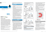
Scanning range in m (feet)
14
(45.93)
Ethernet
USB
„USB 2.0“
Connection
box
delayaction
fuse
0,8A/T
SOPAS
Configuration
Diagnosis
225°
6
(19.69)
TiM
270°
2
Driver for request of
measurement values
and further data
processing
SYNC/
Device Ready
180°
10
(32.81)
DC 9 ... 28 V
(6.56)
0
2
90°
(6.56)
6
„Power/Out“
„Ethernet“
(19.69)
‒45°
10
(32.81)
Measurement mode: Electrical block diagram for commissioning
Step 2: Mounting and alignment
NOTE
During installation make sure there is no reflective surface
behind the reference target see “Device overview Page
3”, point â.
1. Optional: mount the TiM to separately ordered mounting
accessories (mounting kit 2), see "Mounting" Chapter in
the & Technical Information (Nr. 8015883).
2. Otherwise, mount the two straight plates from the
enclosed mounting kit 1 on the TiM using two M3 screws.
Use the two blind-hole threads either on the underside or
back of the housing ( see “Device overview Page 3”).
If the straight plates are not used, screw the screws provided by the customer max. 2.8 mm into the thread.
3. Mount the TiM on a prepared bracket.
The device should be as free from shock and vibration as
possible during operation (e.g. using vibration dampers).
4. Align the 90° axis of the TiM's scanning angle with the
marking on the
center of the area to be monitored. The
lid of the optical hood serves as a bearing alignment aid
( see “Device overview Page 3”, point ã).
0°
14
(45.93)
14
(45.93)
10
(32.81)
6
(19.69)
2
(6.56)
0
2
(6.56)
6
10
14
(19.69) (32.81) (45.93)
Scanning range in m (feet)
Scanning range max. 10 m (32.81 feet)
Scanning range typical 8 m (26.25 feet)
for objects up to 10 % remission
Range diagram for TiM
Step 3: Commissioning/Configuration
a.Installing and launching the SOPAS configuration
software
The SOPAS configuration software is used as standard to display the surrounding contour (measuring line) recorded by the
TiM, as well as diagnostic information in the event of an error.
1. Download and install on the PC the software from the
website “www.mysick.com/en/SOPAS_ET“, software type
SOPAS ET. In this case, select the "Complete" option as
selected by the installation wizard. Administrator rights
may be required on the PC to install the software.
2. Start the "SOPAS" program option after completing the
installation.
Path: Start > Programs > SICK > SOPAS Engineering Tool
> SOPAS.
3. Establish communication between SOPAS and TiM via the
wizard that has started automatically: Select connect to a
new device.
4. Follow the steps in the Connection Wizard until the Found
devices window.
5. Select the appropriate TiM from the list of available
devices:
TiM55x/TiM56x | SICK
1
• Use TiM on port 2111 to configure the device.
• Use TiM on port 2112 to view only measurement data.
Default IP address of the TiM:
b.Output of measured values
Activate the output of the measured values in SOPAS on a
trial basis:
If the TiM receives one of the two following commands by telegram over the Ethernet or USB interface it will start the output
of measured values in real time over these data interfaces.
button.
1. Start the terminal emulator with the
2. Select the Connect... command in the Connections menu
in the dialog window and establish communication with
the TiM over the Ethernet or USB interface.
3. Enter one of the two telegrams in the "Send telegram"
input line as they appear (automatically framed by STX and
ETX when sending in the default setting). Pay attention to
blank characters in the string.
button to transfer the telegram to the TiM.
4. Use the
The TiM responds by providing the data as a one-off or
continuously in the display area of the terminal emulator.
The detailed construction of the output telegram as well
as the flow of requests and outputs is described in the
"Measured value output“ in the & Technical Information
(Nr. 8015883).
6. Assign the required IP address/subnet mask to the TiM
via automatically or Manually. The IP address/subnet
mask should correspond to the address space of the later
application.
7. Click finish to quit the Connection Wizard.
SOPAS ET establishes communication with the TiM, loads
its current device description (parameters), and displays it
in the navigation tree.
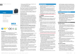
SOPAS ET program window for TiM
One-off output of measured values:
Data output format of the measured values
Telegram layout: sRN LMDscandata
The data output format per scan is comprised of the
measured values (radial distance, RSSI), device and status
information and time stamp.
Telegram part
Description
Variable type
Length
(byte)
Value range
Command type
Request (SOPAS read by name)
string
3
sRN
Command
Request data
string
11
LMDscandata
In the default settings, the distance is output as a measured
value (in mm).
In order to output remission values in the telegram, select the
RSSI checkbox.
Example:
Telegramm type
Command
ASCII
<STX>sRN{SPC}LMDscandata<ETX>
HEX
02 73 52 4E 20 4C 4D 44 73 63 61 6E 64 61 74 61 03
Binary
02 02 02 02 00 00 00 0F 73 52 4E 20 4C 4D 44 73 63 61 6E 64 61 74 61 05
To display the remission values in the scan as well, select the
RSSI... checkbox.
Output range of the measured values
Value range
The TiM scans an angle range of 270°(-45° to 225°) and
outputs 271 measured values per scan in the default setting.
The angle range for which measured values can be output
can be set via Output range (TiM55x: resolution 1°, TiM56x:
resolution 0.33°).
3
sEN
Some other useful functions
11
LMDscandata
1
0 Stop measured value output
1 Start measured value output
Continuous output of measured values:
Telegram structure: sEN LMDscandata measurement start/stop
Navigation tree (left) and respective device pages (right)
Telegram part
Description
Command type
Command
Variable type
Length
(byte)
Request (SOPAS event by name)
string
Request data
string
Enum8
StartStop measurement
Example:
2
TiM55x/TiM56x | SICK
button: Display the fields in the polar coordinate
system
button: Change the view of the TiM from above (TiM:
•
black) to the view from below (TiM: blue)
or
button: Switch off the display the full measur•
ing line or display a dotted measuring line.
•
Telegramm type
Command
ASCII
<STX>sRN{SPC}LMDscandata<ETX>
Completing the configuration
HEX
02 73 52 4E 20 4C 4D 44 73 63 61 6E 64 61 74 61 03
>> Permanently save the entire configuration:
Binary
02 02 02 02 00 00 00 11 73 52 4E 20 4C 4D 44 73 63 61 6E 64 61 74 61 05
button
Parameter set in: TiM click the
button.
Configuration file on the PC: click the
8015886/YDR0/2014-08-27 • Subject to change without notice • SICK AG • Waldkirch • Germany • www.sick.com
Description of the device
Cable no. 6036159 (5 m)
aa CAUTION
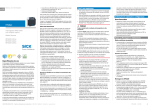
Device overview
2
Laser beam
51 (2.01)
33 (1.3)
44.79 (1.76)
(0.66)
16.79
61 (2.40)
3
4
5
6
30°
‒45°
8
Function
Wire
color
1
24 V
Supply voltage IN (9 ... 28 V)
Brown
2
SYNC/De- Synchronization output
vice Ready
White
Additional information see “Technical data Page 3”.
3
GND SYS
Status indicators, functions
Blue or
Yellow
4
Not assigned
5
Not assigned
*
24.4
46.71 (1.84)
74.39 (2.93)
(0.68)
â
2
2
“Ethernet” connection
Status displays
–
–
Status
LED b
(green)
O
–
–
1
3
2
M12 socket,
D-encoded
1
Device ready/monitoring mode
2
Error
3
Device without supply voltage
4
Pin assignment for swivel connector unit
POWER connection (supply voltage)
Connection “Power”
5-pin M12 plug
180°
3
ã
ä
5
4
All dimensions in mm (inch)
90°
TD+
RD+
TD–
RD–
8015886/YDR0/2014-08-27 • Subject to change without notice • SICK AG • Waldkirch • Germany • www.sick.com
Function of the synchronization output (SYNC/Device Ready)
The synchronization output works with the following levels:
Function
Level
Device Ready
Index signal (15 Hz), corresponds to measurement
at 90°
Error
High
Low peaks
Low
Technical data
1
3
ß Connection "Power/Synchronization output“ 5-pin, M12 outlet
à Marking for the position of the light emission level
á Ethernet connection, 4-pin M12 port
â Area in which no reflective surfaces are allowed for mounted devices
ã Bearing marking to support alignment (90° axis)
ä 270° aperture angle (visual range)
2
1
2
1 2 x straight plates with M3 x 4 mm screw (included in delivery)
2 M3 threaded mounting hole, 2.8 mm deep (blind hole thread)
3 Optical hood
4 Receiving range (light inlet)
5 Transmission range (light emission)
6 Push-button (no function)
7 Red and green LED (status displays)
8 Swivel connector unit with electrical connections and á
9 Micro USB port, behind the black rubber plate
('Aux interface' connection for configuration with PC)
4
O = illuminated; = flashing
225°
0°
Pin assignment of the 5-pin M12 POWER outlet (A-coded), straight, to
the cable and wire colors of the open cable end.
* Push-button with no function
51 (2.01)
Ground
Ethernet connection (6034415)
LED a
(red)
17.37
Illustration may differ
Signal
à
á
9
ß
(0.96)
(0.31)
101.12 (3.98)
85.75 (3.38)
62.46 (2.46)
[24.4
27.3
(0.96)]
(1.07)
8
7
4
M12 - A / Socket
Pin
>> Do not open the screw of the TiM housing.
>> Comply with the latest version of the applicable provisions
on laser protection.
2
0.7 (0.03)
60 (2.30)
[68.8 (2.71)]
[76.25 (3.00)]
1
Caution – incorrect use can lead to the user being exposed to
dangerous radiation.
Mounting set 1
1
3
The TiM corresponds to laser class 1 (eye-safe).
The laser beam is not visible to the human eye.
2x
[Ø
(0. 4.3
17
)]
5
4
5
DC 10 … 28 V
Model name
SYNC/DEVICE READY
TIM551-2050001 (part no. 1060445)
TIM561-2050101 (part no. 1071419)
Scanning range
Radial, aperture angle 270° in 1° steps
GND
Angular resolution
TiM55x: 1°
TiM56x: 0.33°
Scanning frequency
15 Hz (15 scans/s)
Response time
Typical 67 ms (2 scans)
Scanning range
0.05 m ... 10 m; typically 8 m at 10%
remission
Remission
Typical 4% ... > 1,000 % (reflector)
Physical Minimum
object size
(cross-section)
190 mm for a scanning range of 8 m, 100
mm for a scanning range of 4 m, 55 mm for a
scanning range of 2 m and 10% remission
n.c.
n.c.
TiM55x/TiM56x | SICK
3
Model name
TIM551-2050001 (part no. 1060445)
TIM561-2050101 (part no. 1071419)
aa WARNING
Copyright notices for open-source programs
Measurement
error (typically)1)
Statistical (1 s): 20 mm
Systematic: ± 60 mm
Temperature drift 0.5 mm/K
Risk of potential equalization currents
Software licenses
Band width (scan
field flatness)
± 3°
Ambient light
immunity
80,000 lx (indirect)
Light source
Laser diode, infrared (λ = 850 nm)
The TiM is designed to be operated in a system with professional grounding of all connected devices and mounting
surfaces to the same ground potential. If this condition is not
met, potential equalization currents may through along the
cable shields, causing the following hazards:
Max. radiation
power
1,5 W
SICK uses open-source software in its TiM. This software is
licensed by the rights holders under the following free licenses, among others: GNU General Public License (GLP version
2, GPL version 3) and GNU Lesser General Public License
(LGPL), MIT License, zlib License, and licenses derived from
the BSD license.
Max. pulse
duration
5 ns
Device laser class
TiM55x: Laser class 1 according to EN 608251: 2007-102), eye-safe
TiM56x: Laser class 1 according to EN 608251: 2014-052), eye-safe
Output of measured values
Radial distance, reflectivity value, device and
status information, time stamp
Aux interface
USB 2.0 for configuration and measure value
outputs (15 Hz), connecting cable max. 3 m.
Ethernet interface
Max. data rate: 10 Mbit and 100 Mbit, cable
length limited to max. 100 m
Switching inputs
–
Switching outputs
1 x SYNC/Device Ready (Ia ≤ 100 mA),
not electrically isolated from the supply
voltage. Short-circuit protected / temperature
protected
Electrical connections
1 x 4-pin M12 plug (Ethernet)
1 x 5-pin M12 plug (power)
1 x Micro-USB port, type B (covered)
Optical indicators
2 x LED
Supply voltage
DC 9 ... 28 V, SELV according to
IEC 60364-4-41: 2005-12
Power consumption
3 W (with unloaded synchronization output)
Housing
Lower part: Die-cast aluminum, optics hood:
Polycarbonate with scratch-proof coating
Weight
Approx. 250 g
Electrical safety
According to EN 60950-1:2011-01
Protection class
III according to EN 61140: 2006-08
Enclosure rating
IP 67 (EN 60529: 1991-10/A2: 2000-02).
No specified enclosure rating for opened
"Aux interface" connection and/or plugged in
USB cable!
EMC
Radiated emission: Residential area according
to EN 61000-6-3: 2007-01
Electromagnetic immunity: Industrial environment according to EN 61000-6-1: 2007-10
Vibration resistance
According to EN 60068-2-6: 2008-02
Shock resistance
According to EN 60068-2-27: 2009-05
Ambient temperature
Commissioning/switching on: –10 ... +50 °C
Operation: -25 ... +50 °C
Storage: -40 ... +75 °C
Temperature
change
According to EN 60068-2-14: 2009-07
Damp heat
According to EN 60068-2-30: 2005-12
1) For temperatures >-10 °C; without reflectors
2) Complies with 21 CFR 1040.10:2007-04 except for the tolerance according to
Laser Notice No. 50 of June 2007
For further technical specifications, see the Online data sheet
on the product website (www.mysick.com/en/tim5xx)
• Dangerous contact voltage on the metal housing
• Malfunction or destruction of the TiM
• Heating of the cables with possible spontaneous combustion.
>> See the "Electrical Installation" chapter in the & Technical
Information (Nr. 8015883) on the product website (www.
mysick.com/en/tim5xx) for measures for eliminating
hazards.
Scope of delivery
• TiM including mounting kit 1 (two straight plates, 2
M3 x 4 mm screws)
• Printed operating instructions in German and English, in
other languages, as necessary.
• Other optional accessories (if these have been ordered)
Maintenance and care
The TiM does not contain any components that require maintenance. Maintenance is not necessary to ensure compliance
with laser class 1.
>> If it is dirty, clean the infrared light permeable, black
optical hood for optimal measurement/detection performance. Do this carefully using a damp cloth (with a mild
cleaning agent).
Sources for obtaining additional information
Additional information about the TiM and its optional accessories can be found in the following places:
Product web page for the TiM5xx
(www.mysick.com/en/tim5xx)
• Technical Information (supplementary information on
mounting and electrical installation, an overview list, and
license texts for open-source software) in German (no.
8018552) and English (no. 8015883).
• These operating instructions in German (no. 8015885),
English (no. 8015886), and in other languages if required
• SOPAS configuration software with online help
• Ordering information in the detection and ranging solutions product catalog
• Detailed technical specifications (online data sheet)
• Dimensional drawing and 3D CAD dimension models in
various electronic formats
• EC declaration of conformity
• SOPAS configuration software updates
Support is also available from your sales partner:
www.sick.com/worldwide.
8015886/YDR0/2014-08-27 • Subject to change without notice • SICK AG • Waldkirch • Germany • www.sick.com
Exclusion from liability
The firmware of the TiM was developed using open-source
software.
The user is exclusively responsible for any modifications
made to open-source components. All warranty claims shall
be invalidated in this case.
With regard to the rights holders, the following liability
exclusion applies to the GPL components: This program is
distributed in the hope that it will be of use, but without any
warranty; neither is there any implied warranty of marketability or suitability for a particular purpose. For details, see the
GNU General Public License.
With regard to the other open-source components, we refer
to the exclusions from liability of the rights holders in the
license texts.
List of software licenses and license texts
In the TiM product, SICK uses unmodified open-source software and, insofar as required and permitted in accordance
with the relevant license conditions, modified open-source
software.
The firmware of the TiM is therefore subject to the copyrights
listed below.
Please find the corresponding license conditions from the
license texts in the & Technical Information (Nr. 8015883).
The Technical Information document can be downloaded free
of charge from the following address: www.mysick.com/en/
tim5xx.
1. NCURSES – 5.7- License:
Copyright (c) 2006 Free Software Foundation, Inc.
2. Z-Lib 1.2.3:
Copyright (C) 1995-2004 Jean-loup Gailly and Mark Adler
3. binutils-2.18.93.20081009
GNU LESSER GENERAL PUBLIC LICENSE, Version 3, 29
June 2007 Copyright (C) 2007 Free Software Foundation,
Inc
4. e2fsprogs-1.41.11 (UUID-license based on BSD 3-clause
license):
Copyright (C) 1996, 1997 Theodore Ts‘o.
5. Dropbear – 0.52.tar.bz2:
Copyright (c) 2002-2008 Matt Johnston - Portions copyright (c) 2004 Mihnea Stoenescu
5.1 Import code in keyimport.c is modified from PuTTY‘s
import.c, licensed as follows: PuTTY is copyright
1997-2003 Simon Tatham - Portions copyright Robert
de Bath, Joris van Rantwijk, Delian Delchev, Andreas Schultz, Jeroen Massar, Wez Furlong, Nicolas
Barry, Justin Bradford, and CORE SDI S.A.
6. OpenSSH – 5.1p1
6.1 Cryptographic attack detector for ssh - source
code: Copyright (c) 1998 CORE SDI S.A., Buenos
Aires, Argentina.
6.2 Copyright 1995, 1996 by David Mazieres <dm@
lcs.mit.edu>.
6.3 Copyright (c) 1983, 1990, 1992, 1993, 1995 The
Regents of the University of California.
6.4 Remaining components of the software are
provided under a standard 2-term BSD license with
the following names as copyright holders: Markus
Friedl, Theo de Raadt, Niels Provos, Dug Song, Aaron Campbell, Damien Miller, Kevin Steves, Daniel
Kouril, Wesley Griffin, Per Allansson, Nils Nordman,
Simon Wilkinson
Portable OpenSSH additionally includes code
from the following copyright holders, also under
the 2-term BSD license: Ben Lindstrom, Tim Rice,
Andre Lucas, Chris Adams, Corinna Vinschen, Cray
Inc., Denis Parker , Gert Doering, Jakob Schlyter,
Jason Downs, Juha Yrjölä, Michael Stone, Networks
Associates Technology, Inc., Solar Designer, Todd
C. Miller, Wayne Schroeder, William Jones, Darren
Tucker, Sun Microsystems, The SCO Group, Daniel
Walsh
6.5 Portable OpenSSH contains the following additional licenses:
a) snprintf replacement: Copyright Patrick Powell
1995
b) Compatibility code (openbsd-compat): Some
code is licensed under a 3-term BSD license, to
the following copyright holders: Todd C. Miller,
Theo de Raadt, Damien Miller, Eric P. Allma, The
Regents of the University of California, Constantin S. Svintsoff
c) Some code is licensed under an ISC-style
license, to the following copyright holders: Internet Software Consortium: Todd C. Miller, Reyk
Floeter, Chad Mynhier
d) Some code is licensed under a MIT-style license
to the following copyright holders: Free Software
Foundation, Inc.
7. OPENSSL – 09.8N:
7.1 OpenSSL License. Copyright (c) 1998 - 2011 The
OpenSSL Project.
7.2 Original SSLeay License. Copyright (c) 1995 - 1998
Eric Young
8. STRACE – 4.5:20
Copyright (c) 1991, 1992 Paul Kranenburg, Copyright
(c) 1993 Branko Lankester, Copyright (c) 1993 Ulrich
Pegelow, Copyright (c) 1995, 1996 Michael Elizabeth
Chastain, Copyright (c)1993, 1994, 1995, 1996 Rick
Sladkey, Copyright (C) 1998 -2001 Wichert Akkerman
9. GNU GENERAL PUBLIC LICENSE (Version 2, June 1991):
TiM55x/TiM56x | SICK
4
Copyright (C) 1989, 1991 Free Software Foundation, Inc.,
51 Franklin Street, Fifth Floor, Boston, MA 02110-1301
USA
9.1 BusyBox 1.16.1: Copyright (C) 1989, 1991 Free Software Foundation, Inc., 51 Franklin Street, Fifth Floor,
Boston, MA 02110-1301 USA
9.2 iproute2-2.6.34: Copyright (C) 1989, 1991 Free Software Foundation, Inc., 51 Franklin Street, Fifth Floor,
Boston, MA 02110-1301 USA
9.3 kexec-tools-2.0.1: Copyright (C) 1989, 1991 Free
Software Foundation, Inc., 51 Franklin Street, Fifth
Floor, Boston, MA 02110-1301 USA
9.4 libelf-0.8.12.: Copyright (C) 1989, 1991 Free Software
Foundation, Inc., 51 Franklin Street, Fifth Floor, Boston, MA 02110-1301 USA
9.5 libgcc: Copyright (C) 1989, 1991 Free Software Foundation, Inc., 51 Franklin Street, Fifth Floor, Boston, MA
02110-1301 USA
9.6 ltrace-0.5: Copyright (C) 1989, 1991 Free Software
Foundation, Inc., 51 Franklin Street, Fifth Floor, Boston, MA 02110-1301 USA
9.7 lzo-2.03: Copyright (C) 1989, 1991 Free Software
Foundation, Inc., 51 Franklin Street, Fifth Floor, Boston, MA 02110-1301 USA
9.8 mtd-utils-1.3.1: Copyright (C) 1989, 1991 Free Software Foundation, Inc., 51 Franklin Street, Fifth Floor,
Boston, MA 02110-1301 USA
9.9 procps-3.2.8 (only ps used): Copyright (C) 1989, 1991
Free Software Foundation, Inc., 51 Franklin Street,
Fifth Floor, Boston, MA 02110-1301 USA
9.10udev-119: Copyright (C) 1989, 1991 Free Software
Foundation, Inc., 51 Franklin Street, Fifth Floor, Boston, MA 02110-1301 USA
10. libstdc++:
GNU LESSER GENERAL PUBLIC LICENSE (Version 3, 29
June 2007): Copyright (C) 2007 Free Software Foundation, Inc. <http://fsf.org/>
11. Glibc 2.8:
11.1GNU LESSER GENERAL PUBLIC LICENSE (Version 3,
29 June 2007): Copyright (C) 2007 Free Software
Foundation, Inc. <http://fsf.org/>
11.2GNU GENERAL PUBLIC LICENSE (Version 3, 29 June
2007): Copyright © 2007 Free Software Foundation, Inc. <http://fsf.org/>
12. GNU GENERAL PUBLIC LICENSE:
Version 3, 29 June 2007: Copyright (c) 2007 Free Soft ware Foundation, Inc.
12.1dosfstools-3.0.10: Copyright (c) 2007 Free Software Foundation, Inc.
12.2gnupg-1.4.10: Copyright (c) 2007 Free Software Foundation, Inc.
12.3binutils-2.18.93.20081009: Copyright (c) 2007
Free Software Foundation, Inc.
Source codes
The source codes licensed under GPL and LGPL can be
ordered from the responsible SICK national representative.
Contact data: www.sick.com/worldwide
5
TiM55x/TiM56x | SICK
8015886/YDR0/2014-08-27 • Subject to change without notice • SICK AG • Waldkirch • Germany • www.sick.com
8015886/YDR0/2014-08-27 ∙ 8M_SH ∙ Printed in Germany (2014-08) ∙ All rights reserved ∙ Subject to change without notice
8015886/YDR0/2014-08-27 • Subject to change without notice • SICK AG • Waldkirch • Germany • www.sick.com
TiM55x/TiM56x | SICK
6





![[1]StorageTek T10000C](http://vs1.manualzilla.com/store/data/005701279_1-def8e2b4b691d6a17c8293fd164d2b7c-150x150.png)