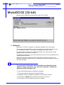
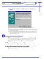
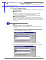
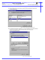
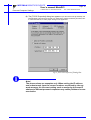
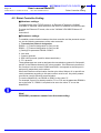
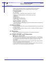
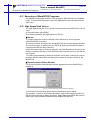
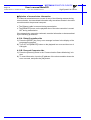
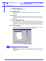
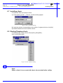
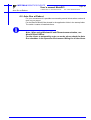
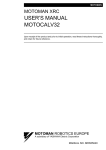
1
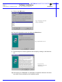
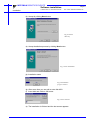
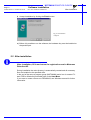
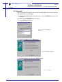
MOTOMAN
MOTOMAN XRC
USER’S MANUAL
MotoDCI32
Upon receipt of the product and prior to initial operation, read these instructions thoroughly,
and retain for future reference.
MOTOMAN ROBOTICS EUROPE
A subsidiary of YASKAWA Electric Corporation
MANUAL NO. MRS55120
MOTOMAN ROBOTICS EUROPE
Reference list
Basic Operator’s Manual
Windows User’s Manual
Revision
000316
Preliminary issue of this manual.
000704
Second preliminary issue of the manual MotoDCI32, made with same
texts as used for orginal manual (Scanned document).
000706
Brand new version of this manual (based on support file).
MOTOMAN ROBOTICS EUROPE
User’s manual MotoDCI
Created: 00-07-06 Revised: 00-07-06
Page: I
Doc. name: Mrs55120TOC.fm
1. General ................................................................. 1
Copyright
MotoDCI32-kit
❏ MotoDCI-kit comprises
❏ MotoDCI-kit does not comprise
❏ Further you may have need for
Hardware Requirements for MotoDCI32
2
2
2
2
2
2
2. Software installation ............................................. 3
Installation
After installation
Uninstall
3
6
7
3. Introduction ........................................................... 9
Introduction of this manual
Features of Ethernet Communications
❏ High speed transmission
❏ Transmissions between a multiple number of HOSTS
Hardware Lock Key
9
9
9
10
12
4. SETUP ................................................................ 15
Execution of setup program
❏ Set up the MotoDCI32 in the following manner.
Environmental Settings for Use of Ethernet
Environment MotoDCI32 Application Settings
Personal Computer Settings
❏ Hardware settings
❏ Windows Network settings
Robot Controller Setting
❏ Hardware settings
❏ Parameter settings
Network Setting
Restrictions
YASNAC XRC/MRC and PC Restrictions
❏ The port used for TCP/IP
Personal Computer Restrictions
❏ Same file access
YASNAC Robot Controller Restrictions
❏ Multiple personal computer access
❏ CMOS batch storage
Execution of MotoDCI32 Programs
High Speed Link Server
❏ Server
❏ Communication Status Monitor
❏ Deletion of transmission information
Editing of Language Files
❏ Editing Language Files
❏ Creating New Language Files
15
15
16
16
17
17
17
20
20
20
21
21
21
21
22
22
22
22
22
23
23
23
23
24
25
25
25
MOTOMAN ROBOTICS EUROPE
User’s manual MotoDCI
Page: II
Created: 00-07-06 Revised: 00-07-06
Doc. name: Mrs55120TOC.fm
5. MotoDCI32 operation ......................................... 27
Startup
Operation of MotoDCI32
❏ Run
❏ Stop
Option Menu
❏ (1) Setting transmission parameters
❏ (2) Selecting the robot model
❏ (3) Selecting a folder
Display Logging File
Clear Messages
Auto Run
Write Logging Message
Select Language
27
28
28
28
29
29
30
30
31
31
31
31
31
6. Help Menu .......................................................... 33
MotoDCI32 Help
YASNAC Help
Version Information
MotoDCIShell32 OPERATION
Operation of MotoDCIShell32
Register clients
Installing clients
Starting/Stopping clients
Auto Run at Reboot
33
33
33
33
33
33
34
34
35
MOTOMAN ROBOTICS EUROPE
User’s manual MotoDCI
Created: 96-01-31 Revised: 00-07-06
Page: 1
Doc. name: Mrs55120-ch1.fm
MotoDCI32 (32-bit)
Manual valid for MotoDCI32 (Motoman part No. 441141-99).
1. General
MotoDCI is a 32-bit PC-software, for Windows (95/98 0r NT) environment.
The purpose with MotoDCI is to make it possible for the robot controller to use a
PC as external memory. The memory use is possible at PLAY mode.
By using the DCI-instructions LOADJ and SAVEJ in the robot job, job can be
loaded / stored / saved from / to the PC.
The DCI-functions can be used if the robot memory is full or if some jobs has to be
updated within operation.
While communication parameters have been set on both robot and PC, the
MotoDCI software is started on the PC. MotoDCI will execute instructions told by
the robot controller.
For more basic information about installation and handling of the
software, icons, menu bars, etc. refer to the operator’s manual for
Windows 95/98 or Windows NT.
✔ This manual shall always be available to operator.
✔ This User’s Manual comprises information about
✔ Installation / Setup / Handling / operation for XRC robot controller
✔ Text written in BOLD letters means command, icon or button.
✔ Text written in ITALIC means text shown on display.
MOTOMAN ROBOTICS EUROPE
User’s manual MotoDCI
Page: 2
Created: 96-01-31 Revised: 00-07-06
Doc. name: Mrs55120-ch1.fm
Copyright
1.1 Copyright
The diskettes for MotoDCI32-program may not be copied or imparted to a third
party nor be used for an unauthorized purpose. Copies may be done only for own
backup.
This manual may not be copied or imparted to a third party nor be used for an
unauthorized purpose.
1.2 MotoDCI32-kit
■ MotoDCI-kit comprises
✔ Diskettes (for MotoDCI and drivers) or CD-ROM
✔ Hardware key
✔ One manual
✔ One registration card
■ MotoDCI-kit does not comprise
✔ Cables or adapters, etc.
■ Further you may have need for
✔ Programming manual for your robot controller.
✔ Operator’s manual for Windows 95/98 or Windows NT.
1.3 Hardware Requirements for MotoDCI32
The MotoDCI32 operates with the configurations shown in Table 1.
OS
CPU
Required memory
Hardware disk
capacity for installation
Disk drive
Display
Mouse
Robot controller
Transmission cable
Hardware lock key
Microsoft Windows 95 / 98 or NT4.0
Pentium or pentium compatible processor
16 Mbyte or more
30 Mbyte or more
Hard disk and CD-ROM drive
Supported by MS Windows
Supported by MS Windows
YASNAC XRC, MRC, MRC2, ERC, ERC2
Ethernet cable or RS232C cable
Single user registration.
If an conversion adapter is required, refer to “Hardware
Lock Key” for details.
Note!
1) A personal computer, transmission cable, and OS are not included with this
software.
2) Use either an RS-232C cable or an Ethernet cable for transmission, depending
on the data transmission function specifications set in the robot controller
manuals. Before starting this software, check the hardware and software specifications of the robot controllers.
3) Ethernet transmission is not available for the YASNAC ERC / ERC2 since they
do not support the Ethernet function.
MOTOMAN ROBOTICS EUROPE
Software installation
Installation
Created: 96-01-31 Revised: 00-07-06
Page: 3
Doc. name: Software-installation.fm
2. Software installation
Note
This chapter shows a general installation phase of any software. In this example
the software FDDWIN is installed. Select the right software by choosing the
appropriate software name.
2.1 Installation
There are three ways to start installation of this software, all will give the same
result. The most common way is described below.
a) Put the first diskette named #1 in the disk-drive.
b) Click on the Start button on the menu-bar.
c) Choose Run from the menu.
d) Browse to drive A:\
e) Choose the file named SETUP.EXE
f) Click OK.
Fig.1 Choose installation file
g) Choose OK and the installation guide will start.
h) You can quit the installation att any time by clicking the Cancel-button and
then confirm by Yes-button.
Fig.2 You can cancel
installation at any time
i) Mark the language you want to use during installation. Note! This will not influence the language you use in FDDWIN32 later.
MOTOMAN ROBOTICS EUROPE
Software installation
Page: 4
Created: 96-01-31 Revised: 00-07-06
Installation
Doc. name: Software-installation.fm
j) Click on the OK-button.
Fig.3 Language selection
during installation
k) Pass this information screen by clicking the Next-button.
Fig.4 Information screen
l) Read through the license agreement and accept by clicking on the Next-button.
Fig.5 License
agreement. Accept by
clicking Next.
m) Set directory for FDDWIN32. It’s advisable to install the software in the directory which is set as default by the installation guide.
MOTOMAN ROBOTICS EUROPE
Software installation
Installation
Created: 96-01-31 Revised: 00-07-06
Page: 5
Doc. name: Software-installation.fm
n) Accept by clicking Next-button.
Fig.6 Choose
directory
o) Accept installation process by clicking Next-button.
Fig.7 Start installation
p) Installation starts.
Fig.8 Installation
progress counter
q) After some time you are told to enter disk #2/2.
r) Insert disk and click on OK-button.
Fig.9 Insert disk #2
s) The installation is finished and the last screen appears.
MOTOMAN ROBOTICS EUROPE
Software installation
Page: 6
Created: 96-01-31 Revised: 00-07-06
After installation
Doc. name: Software-installation.fm
t) Accept installation by clicking the Finish-button.
Fig.10 Installation
complete
u) Before it is possible to run the software, the hardware key must be installed on
the parallel port.
2.2 After installation
After installation, fill in and return the registration card to Motoman
Robotics AB.
During installation the main directory is automatically created and all necessary
files are installed in the specified drive.
In the end of the setup a program group (MOTOMAN) and a icon is created. To
start FDD for Windows just double-click on the Start Menu.
If you want to create a shortcut to FDDWIN32, see Windows manual for further
information
MOTOMAN ROBOTICS EUROPE
Software installation
Uninstall
Page: 7
Created: 96-01-31 Revised: 00-07-06
Doc. name: Software-installation.fm
2.3 Uninstall
As in all WIN95/NT softwares there are an uninstall facility if you want to remove
the software from the hard disk.
a) Start the Control panel from the start menu. Select Add/Remove button from
the menu.
b) Mark the line FDDWIN32 from the menu.
c) Click Add/Remove button.
Fig.11 Mark the FDDWIN32
software
d) Activate uninstall guide by Next-button.
Fig.12 Automatic uninstall
e) End the operation by clicking the Finish-button.
Fig.13 Uninstall
MOTOMAN ROBOTICS EUROPE
Page: 8
Created: 96-01-31 Revised: 00-07-06
Software installation
Doc. name: Software-installation.fm
Uninstall
MOTOMAN ROBOTICS EUROPE
User’s manual MotoDCI
Introduction of this manual
Created: 96-01-31 Revised: 00-07-06
Page: 9
Doc. name: Mrs55120-ch3.fm
3. Introduction
3.1 Introduction of this manual
This operation manual is for the users of the data transmitting function of
industrial robot MOTOMAN controller YASNAC XRC, MRC, MRC2, ERC, and
ERC2.
This operation manual outlines the operation method of the personal computer
software MotoDCI32 for data transmission between the robot controller and a
personal computer, and at the same time, the specifications of the supplied data
transmission function.
Read this operation manual thoroughly before use.
3.2 Features of Ethernet Communications
The Ethernet I/F board and the "Ethernet" function of the MotoDCI32 transmit
data at higher than normal speeds.
■ High speed transmission
In comparison with transmissions using RS232C, higher speed transmissions are
possible with the Ethernet.
When Ethernet is used:
Personal computer
Robot
Controller
When RS232C is used:
Personal computer
Robot
Controller
Fig.1 Transmission Speed
Note!
The above transmission speed is the communication speed between
network devices, not including the time used for format check of
transmitted data, etc.
MOTOMAN ROBOTICS EUROPE
User’s manual MotoDCI
Page: 10
Created: 96-01-31 Revised: 00-07-06
Doc. name: Mrs55120-ch3.fm
Features of Ethernet Communica-
■ Transmissions between a multiple number of HOSTS
As N:N transmission is possible with an Ethernet cable, the following system
configurations can be prepared.
Note!
Refer to paragraph "Restrictions" with the following Configuration
Examples.
✔ Configuration Example 1
Since an Ethernet cable can be connected to a multiple number of network devices, the factory operation state and alarm occurrences can be monitored from
several places.
Monitoring
room A
Factory
Monitoring
room B
Personal
computer
Robot
Controllers
Fig.2 Configuration Example 1
✔ Configuration Example 2
By connecting the LANs of different factories with one Ethernet cable, transmission in each factory can be executed simultaneously. The transmission between
the robot controller and the personal computer in factory A does not interfere with
the transmission between the robot controller and the personal computer in factory B.
Transmission can also be done between factories. (In both cases, the settings
should be correct.)
LAN in A
LAN in B
factory
factory
Personal computer
Personal
computer
Robot
Controllers
Robot
Controller
Fig.3 Configuration Example 2
MOTOMAN ROBOTICS EUROPE
User’s manual MotoDCI
Features of Ethernet Communica-
Created: 96-01-31 Revised: 00-07-06
Page: 11
Doc. name: Mrs55120-ch3.fm
✔ Configuration Example 3
With the Ethernet cables, the job on a personal computer can be executed on the
robot controller by installing a personal computer for each production line and
transferring the job from the personal computers to the robot controller. Then, by
connecting one personal computer to the Ethernet cables in all the production
lines, monitoring of the state of all the production lines and data backup can be
executed.
A line
B line
C line
Personal
Robot
Controller computer
Robot
Controllers
Personal
computer
Robot
Controllers
Personal
computer
Personal
computer
Fig.4 Configuration Example 3
Note!
When using an Ethernet cable, the RS232C cable is not
required.
MOTOMAN ROBOTICS EUROPE
User’s manual MotoDCI
Page: 12
Created: 96-01-31 Revised: 00-07-06
Hardware Lock Key
Doc. name: Mrs55120-ch3.fm
The cable connection for communications via RS232C is shown in
figures below.
(IBM PC/AT)
Robot controller
(D-sub 25-pin male)
Personal computer
(D-sub 9-pin female)
(PC9801)
Robot controller
(D-sub 25-pin male)
Personal computer
(D-sub 25-pin male)
Fig.5 RS232C Cable Connection
3.3 Hardware Lock Key
For proper operation, connect the attached hardware lock key to the personal
computer.
Two types of hardware lock keys are available :
✔ Anphenole type
✔ D-sub type
Normally, a D-sub type hardware lock key is attached.
Connection when using a PC-AT compatible personal computer
When using a PC-AT compatible personal computer such as a PC98-NX series
NEC personal computer, connect the hardware lock key to the printer port.
Connection when using a personal computer other than PC-AT
compatibles
When using an anphenole type hardware lock key, the form of printer port differs
depending on the computer model. Connect the key as shown in the figure below
"Anphenole Type".
When using a D-sub type hardware lock key, install a conversion adapter between
the printer port of the personal computer and the hardware lock key. The conversion adapter should be prepared at customer side. See figure.
MOTOMAN ROBOTICS EUROPE
User’s manual MotoDCI
Hardware Lock Key
Created: 96-01-31 Revised: 00-07-06
Page: 13
Doc. name: Mrs55120-ch3.fm
✔ Anphenole Type
MotoDCI32
Hardware lock key
Anphenole
36pin
Printer cable
(differs depending on the
model of personal computer)
NEC personal
computer
Anphenole
36pin
Fig.6 Hardware lock key anphenole type
✔ D-sub Type
Conversion adapter
ZA-510
(made by LOAS Co. Ltd.)
MotoDCI32
Hardware lock key
Printer cable
(differs depending on the
model of personal computer)
Anphenole
36pin
NEC personal
computer
MOTOMAN ROBOTICS EUROPE
Page: 14
Created: 96-01-31 Revised: 00-07-06
User’s manual MotoDCI
Doc. name: Mrs55120-ch3.fm
Hardware Lock Key
MOTOMAN ROBOTICS EUROPE
User’s manual MotoDCI
Execution of setup program
Created: 96-01-31 Revised: 00-07-06
Page: 15
Doc. name: Mrs55120-ch4.fm
4. SETUP
4.1 Execution of setup program
■ Set up the MotoDCI32 in the following manner.
1) Turn ON the power to the personal computer and the display.
2) Start up Windows.
3) Insert the MotoDCI32 installation CD-ROM into the CD-ROM drive.
4) Click the [Start] button in the task bar and select [Setting]. Double-click the
[Add/Remove Programs] icon from [Control Panel]. The [Add/Remove
Programs Properties] display appears.
Fig.7 [Add/Remove Programs Properties] Display
MOTOMAN ROBOTICS EUROPE
User’s manual MotoDCI
Page: 16
Created: 96-01-31 Revised: 00-07-06
Doc. name: Mrs55120-ch4.fm
Environmental Settings for Use of
5) Click the [Install] button and follow the instructions in the display to set
"setup.exe" of the CD-ROM drive. The [Run Installation Program] dialog box
appears.
Fig.8 [Run Installation Program] Dialog Box
6) Clicking the [Finish] button calls up the setup program. Follow the instructions
in the proceeding display.
7) When the setup is completed, [MotoDCI32] is registered under [MotoDCI32]
folder that appears by clicking the [Start] button in the task bar to select [Program] and then [Motoman].
Note!
To re-install the MotoDCI32 for some reasons, select [MotoDCI32]
in the [Add/Remove Program Properties] Display shown in the Fig.
and delete all the MotoDCI32 application files before starting reinstallation.
4.2 Environmental Settings for Use of Ethernet
The following configurations are required for Ethernet transmissions. These
settings are not necessary for the RS232C communication. Refer to "Operation
4.3 Environment MotoDCI32 Application Settings
To communicate with the robot controller, set the IP address etc., as a
transmission parameter.
MOTOMAN ROBOTICS EUROPE
User’s manual MotoDCI
Personal Computer Settings
Created: 96-01-31 Revised: 00-07-06
Page: 17
Doc. name: Mrs55120-ch4.fm
4.4 Personal Computer Settings
Set the settings related to Ethernet transmissions, to the personal computer with
the software installed.
■ Hardware settings
Before using the MotoDCI32, connect the Ethernet board to the personal
computer and check if the Ethernet board operates correctly.
For connection methods, refer to the manual for the Ethernet board used.
■ Windows Network settings
To communicate via the Ethernet, set the settings related to the Windows network. Click the [Start] button in the task bar and select [Setting]. Double-click the
Network" icon from [Control Panel]. The [Select Network Component Type] Dialog
box appears.
Note!
The example below is based on Windows95.
1) Click the [Add] button. The [Select Network Component Type] dialog box
appears.
2) Select [Adapter] from the list and click the [Add] button to set the Ethernet
board for adapter. Choose the network adapter that is added to the personal
computer as mentioned in "Hardware setting".
Fig.9 Selecting Adapter
3) Select the [Protocol] from the list and click the [Add] button, to set protocol.
The [Select Network Protocol] dialog box appears.
Fig.10 Selecting Protocol
MOTOMAN ROBOTICS EUROPE
User’s manual MotoDCI
Page: 18
Created: 96-01-31 Revised: 00-07-06
Doc. name: Mrs55120-ch4.fm
Personal Computer Settings
4) Select [Microsoft] as manufacturers and [TCP/IP] as Network Protocol and
click the [OK] button.
Fig.11 [Select Network Protocol] Dialog Box
5) The [Network] dialog box appears. To set the IP address and subnet mask for
the personal computer, select [TCP/IP] protocol from the list and
click the [Properties] button.
Fig.12 [Network] Dialog Box
MOTOMAN ROBOTICS EUROPE
User’s manual MotoDCI
Personal Computer Settings
Created: 96-01-31 Revised: 00-07-06
Page: 19
Doc. name: Mrs55120-ch4.fm
6) The [TCP/IP Properties] dialog box appears. Input the value for the [IP address] and
[Subnet Mask] of the personal computer. For details of the settings of Gateway and DNS, refer
to a Windows manual, to make proper settings for the application.
Fig.13 [TCP/IP Properties] Dialog Box
Note!
The above values are examples only. When setting the IP address
and subnet mask, input the correct numbers as advised by the network manager. An incorrect setting such as assigning the same IP
address to different personal computers may cause problems in communication.
MOTOMAN ROBOTICS EUROPE
User’s manual MotoDCI
Page: 20
Created: 96-01-31 Revised: 00-07-06
Doc. name: Mrs55120-ch4.fm
Robot Controller Setting
4.5 Robot Controller Setting
■ Hardware settings
To communicate using TCP/IP protocol, an Ethernet I/F board for YASNAC
XRC/MRC is required. Insert the board, and set the IP address and subnet mask.
To setup the Ethernet I/F board, refer to the "YASNAC XRC/MRC Ethernet I/F
Board
Instructions".
■ Parameter settings
To establish communication between the robot controller and the personal computer, set the following parameters of the robot controller.
✔ Transmission protocol designation
RS000 = (*) Protocol designation for Std. port #1
RS001 = (*) Protocol designation for Std. port #2
(*) Settings for parameter RS000 / RS001 :
0 : Not used
1 : System reserved
2 : BSC LIKE protocol (used for data transmission)
3 : FC1 protocol
These parameters are used to designate the transmission protocol for Std port #1,
port #2 or the Ethernet board for the robot controller. If the Ethernet communication function is not to be used, RS000 and RS001 correspond to the Std port #1
and port #2 respectively as the above.
When the Ethernet communication function plus either Std port #1 or port #2 are
used, parameters according to this port number must be set. Any other parameters can be used for Ethernet communication.
To use the MotoDCI32, set RS000 or RS001 to the value "2".
For example, if port #1 is already used for FC1 or FC2 and its parameter RS000 is
set to the value "3," RS001 is required to be set to the value "2" to use the
MotoDCI32.
Note!
RS000/001 parameters cannot have the same setting.
MOTOMAN ROBOTICS EUROPE
User’s manual MotoDCI
Network Setting
Created: 96-01-31 Revised: 00-07-06
Page: 21
Doc. name: Mrs55120-ch4.fm
Ethernet communication function only supports the BSC LIKE protocol.
Some parameters have to be set in "Maintenance mode" using the
programming pendant.
✔ Customer options
I/O = Not used
Command mode = Used (This must be always set to "Used".)
PP/PBOX (programming pendant / playback box)= Not used
✔ Ethernet
Ethernet = Used
IP ADDRESS = 192.168.10.10*
SUBNET MASK = 255.255.255.0*
DEFAULT GATEWAY = 192.168.10.1*
SERVER ADDRESS = 192.168.10.11*
* The above values are examples only. Input the suitable values according to your
network environment.
4.6 Network Setting
To communicate with the robot controller using the MotoDCI32, the network must
be set up correctly.
For details on how to setup the network, refer to "YASNAC XRC/MRC Ethernet I/
F Board Instructions".
4.7 Restrictions
When using the MotoDCI32, pay attention to the following restrictions.
4.8 YASNAC XRC/MRC and PC Restrictions
■ The port used for TCP/IP
The MotoDCI32 uses TCP/IP for the communication protocol. To communicate
in TCP/IP, the service identification numbers called "Port No" are used internally,
while MotoDCI32 uses the port numbers from 10000 to 10008 for the data
transmission.
When these numbers overlap with the numbers used for other network devices,
correct communication cannot be performed.
To use the MotoDCI32, be sure in advance that any network device in the same
network does not use the above explained port numbers.
MOTOMAN ROBOTICS EUROPE
User’s manual MotoDCI
Page: 22
Created: 96-01-31 Revised: 00-07-06
Personal Computer Restrictions
Doc. name: Mrs55120-ch4.fm
4.9 Personal Computer Restrictions
■ Same file access
The same file in the personal computer cannot be accessed from different robot
controllers simultaneously.
Job
Job
Ethernet
Robot
Controller
Robot
Controller
Fig.14 Access to the Same File by Multiple Robot controllers not Possible
4.10 YASNAC Robot Controller Restrictions
■ Multiple personal computer access
With the MotoDCI32, one personal computer can communicate with one robot
controller. Simultaneous communication with a multiple number of personal computers is not possible.
(On the contrary, the simultaneous comunication between one personal computer
and a multiple number of robot controllers is possible.)
Job
Job
Ethernet
Robot
Controller
Fig.15 Access from a Multiple Personal Computers not Possible
■ CMOS batch storage
The BSC LIKE protocol and the FC1 protocol are available for the controller to
communicate with external devices. The MotoDCI32 uses the BSC LIKE protocol
for transmission. As the CMOS batch storage uses the FC1 protocol, CMOS batch
storage is not available in the MotoDCI32. For CMOS batch storage, use the
YASNAC FC1/FC2.
MOTOMAN ROBOTICS EUROPE
User’s manual MotoDCI
Execution of MotoDCI32 Programs
Created: 96-01-31 Revised: 00-07-06
Page: 23
Doc. name: Mrs55120-ch4.fm
4.11 Execution of MotoDCI32 Programs
The MotoDCI32 program consists of two programs; [MotoDCI32] and [YASNAC
Help]. To execute each program, select the application to be executed from the
start menu.
4.12 High Speed Link Server
The High Speed Link Server is used for communication via the Ethernet. It is not
used
for communication via RS232C.
The following explains the High Speed Link Server.
■ Server
To communicate with a robot controller via the Ethernet, a server program
(HSLSR32.EXE) is required.
The server receives a request from the MotoDCI32 and sends/receives the data.
The server program is started up from VRP32.dll when the MotoDCI32 starts to
communicate with the robot controller.
When the transmission is finished, right-click the [High Speed Link Server] in the
task bar to display the menu. Click the [Exit] button from the menu to exit the server program.
To communicate between a personal computer and a robot controller, the server
program and the related DLL files have to be located in the same folder as the
MotoDCI32.
■ Communication Status Monitor
The [Communication Status Monitor] display appears when the MotoDCI32 is
started up.
Fig.16 [Communication Status Monitor] Display
To hide the [Communication Status Monitor] window for some reason
(for example, to work on by another operation), right-click the [High Speed Link
Server] in the task bar to display the menu. Select [Monitoring] from the menu to
switch the [Communication Status Monitor] display ON and OFF.
MOTOMAN ROBOTICS EUROPE
User’s manual MotoDCI
Page: 24
Created: 96-01-31 Revised: 00-07-06
Doc. name: Mrs55120-ch4.fm
High Speed Link Server
■ Deletion of transmission information
If a Ethernet transmission error occurs for any of the following reasons during
communication, the transmitted information may sometimes remain in the robot
controller and/or the personal computer.
✔ The Ethernet cable is removed during transmission.
✔ The [REMOTE] button on the playback box of the robot controller is turned
OFF during transmission.
If the transmission cannot be continued, reset the information to be transmitted
by the following procedures.
4.12.A Robot Controller side
1) Press the [RESET] key if any error message is shown in the display of the
programming pendant.
2) Turn OFF the [REMOTE] button on the playback box once and then turn it
ON again.
4.12.B Personal Computer side
1) Press the [Remove] button in the "Communication Status Monitoring" window.
2) To reset information, input the IP address of the robot controller where the
error occurred, and press the [OK] button.
MOTOMAN ROBOTICS EUROPE
User’s manual MotoDCI
Editing of Language Files
Created: 96-01-31 Revised: 00-07-06
Page: 25
Doc. name: Mrs55120-ch4.fm
4.13 Editing of Language Files
■ Editing Language Files
In the "Select Language" dialog box, press the [Edit] button. The language
file of the currently selected language is opened in the Windows Notepad.
Using Notepad, the language file can be edited.
Note!
Since the language files are important parts of the software,
extreme care must be taken during modification.
■ Creating New Language Files
<Adding another language>
Modification can be carried out from the use of Windows Notepad.
If you want to add a language which is not yet available, follow the instructions below:
✔ [Example : Chinese]
a) Copy the "English.lng" file, then rename it "User13.lng".
Note!
Do not rename it "Chinese.lng".
b) In the "User13.lng" file, change "English" to "Chinese" and place the Chinese
language translation of each word in the file.
c) If you want to add more languages, continue with "User14.lng" and so
on.
Note!
The new languages are not displayed under the "System"
language. By selecting "User13," the Chinese language appears.
MOTOMAN ROBOTICS EUROPE
Page: 26
Created: 96-01-31 Revised: 00-07-06
User’s manual MotoDCI
Doc. name: Mrs55120-ch4.fm
Editing of Language Files
MOTOMAN ROBOTICS EUROPE
User’s manual MotoDCI
Startup
Created: 96-01-31 Revised: 00-07-06
Page: 27
Doc. name: Mrs55120-ch5.fm
5. MotoDCI32 operation
Using DCI (Data Communication by Instruction) transmitting function, any job in
the controller can be transmitted.
If the robot memory runs short because there are too many types of workpieces
or a job becomes excessively long due to a complicated job, a personal computer
can be used as an external memory. In such a case, the DCI instructions can be
used to upload/download jobs.
5.1 Startup
To start up the [MotoDCI32], click the [Start] button and point to [Program], and
select [Motoman], and then [MotoDCI32]. The [Select Language] display appears
as shown in Fig. 4.1. Select a desired language and click the [OK] button. The
language can be changed at any time from the main menu of this application.
Fig.17 [Select Language] Display
By marking the box [Ignore language selection at program start], the
[Select Language] window is not displayed when starting the the application. This
can be changed at any time by selecting [Select Language] from the main menu
of this application.
MOTOMAN ROBOTICS EUROPE
User’s manual MotoDCI
Page: 28
Created: 96-01-31 Revised: 00-07-06
Doc. name: Mrs55120-ch5.fm
Operation of MotoDCI32
5.2 Operation of MotoDCI32
When MotoDCI32 is executed, the following display appears.
■ Run
Pressing the run button makes the MotoDCI32 wait for a request from the
controller. Depending on instructions used in the controller, jobs will be transferred
from/to the controller.
Note!
During automatic operation, the grayed functions in the display such
as robot change cannot be used.
Fig.18 MotoDCI32 Main Menu
■ Stop
Terminates run mode. Normally, stop the DCI operation first from the controller
side. If the personal computer is terminated first, an alarm may occur on the
controller side.
Note!
It may take some time until the stopped status is actually entered after
the stop button is pressed.
MOTOMAN ROBOTICS EUROPE
User’s manual MotoDCI
Option Menu
Created: 96-01-31 Revised: 00-07-06
Page: 29
Doc. name: Mrs55120-ch5.fm
5.3 Option Menu
The following functions are provided in the option menu.
5.3.A Operation Environment
The environmental settings define the settings for the personal computer.
Selecting this menu calls up the display shown in fig. Set each item in this display.
Fig.19 Setting Transmission Parameters
■ (1) Setting transmission parameters
Select the controller and communications protocol and choose their settings as
shown in fig. There are two types of communications; the Ethernet and RS-232C
transmission. Click the radio button to select one.
✔ Communications parameters for Ethernet transmissions:
Only the IP address can be set for the Ethernet transmission. Enter the IP
address assigned to the controller connected to the network.
✔ Communications parameter for RS2-233C transmissions:
Select the port number, baud rate, data length, parity, and stop bit according to
the controller settings. Click the "Reset" button to set to the default data.
MOTOMAN ROBOTICS EUROPE
User’s manual MotoDCI
Page: 30
Created: 96-01-31 Revised: 00-07-06
Doc. name: Mrs55120-ch5.fm
Option Menu
■ (2) Selecting the robot model
Select the controller model for transmission in the display shown in the fig.
Fig.20 Selecting a Robot Model
■ (3) Selecting a folder
Select the folder for communications in the display shown in Fig. 4.5. Once the
drive and folder are specified in this display, the files transferred with the commands LOADJ and SAVEJ are retrieved/stored here.
Fig.21 Selecting a folder
MOTOMAN ROBOTICS EUROPE
User’s manual MotoDCI
Display Logging File
Created: 96-01-31 Revised: 00-07-06
Page: 31
Doc. name: Mrs55120-ch5.fm
5.4 Display Logging File
Displays the contents of a log file.
5.5 Clear Messages
Deletes the run mode messages. Messages are deleted periodically by
the program.
5.6 Auto Run
Determines whether run mode is to be entered at the same time as startup of
MotoDCI32. A check mark at the left side of the menu means that run mode will
be entered.
5.7 Write Logging Message
Determines whether a communication log is to be taken at run mode. A check
mark at the left side of the menu means that the log is going to be taken. A log file
is created in the directory where the MOTOCOM32 is installed with the name of
"ONLINE.LOG". The program is overwritten when this file exceeds a certain size.
5.8 Select Language
Change the language displayed in the application according to the environment.
Selecting this menu displays the Select Language dialog box.
Fig.22 [Select Language] dialog
Note!
Some languages may not be correctly displayed unless fonts are set
correctly.
MOTOMAN ROBOTICS EUROPE
Page: 32
Created: 96-01-31 Revised: 00-07-06
User’s manual MotoDCI
Doc. name: Mrs55120-ch5.fm
Select Language
MOTOMAN ROBOTICS EUROPE
User’s manual MotoDCI
MotoDCI32 Help
Created: 96-01-31 Revised: 00-07-06
Page: 33
Doc. name: Mrs55120-ch6.fm
6. Help Menu
The following functions are provided in the Help menu.
6.1 MotoDCI32 Help
Starts up the on-line help to explain the MotoDCI32.
6.2 YASNAC Help
Starts up the on-line help to explain the robot transmission commands, transmission instructions, alarms, and interpreter messages.
6.3 Version Information
Displays the version information.
6.4 MotoDCIShell32 OPERATION
MotoDCIShell32 is a optional software for managing several clients of
MotoDCI32.
MotoDCIShell32 includes tools for installing, starting/stopping and setting
environmental settings for the clients.
6.5 Operation of MotoDCIShell32
When MotoDCI32 is executed, the display of fig appears.
Fig.23 MotoDCIShell32 Main Menu
6.6 Register clients
To register the serial and check no. included in the software package, proceed as
follows.
1) Click [File], [Register Serialno. …]. The Register dialog appears.
Fig.24 The register dialog
2) Input the values and click [Ok].
MOTOMAN ROBOTICS EUROPE
User’s manual MotoDCI
Page: 34
Created: 96-01-31 Revised: 00-07-06
Doc. name: Mrs55120-ch6.fm
Installing clients
6.7 Installing clients
To install the clients proceed as follows.
1) Click [Option], [Install…]. The No. of Robots dialog appear.
Fig.25 The No. of Robots dialog
2) Input the number corresponding to the number of registered clients, click [Ok].
3) MotoDCIShell32 will now install the clients.
6.8 Starting/Stopping clients
To start/stop one or more clients click [Option], [Start]/[Exit],
then choose [Rbtxx]/[All].
Fig.26 The No. of Robots dialog
Note!
When a client is in run mode this has to be canceled before exiting.
MOTOMAN ROBOTICS EUROPE
User’s manual MotoDCI
Auto Run at Reboot
Created: 96-01-31 Revised: 00-07-06
Page: 35
Doc. name: Mrs55120-ch6.fm
6.9 Auto Run at Reboot
For your convenience it is possible to automaticly start all clients when a reboot is
done on your server.
Put the MotoDCIShell32.bat located in the application-folder in the startup-folder.
The switch /a starts all installed clients.
Note : When using Windows95 and Ethernetcommunication, use
MotoDCIShell32E.bat.
For the clients to automaticly enter run mode, please check the Auto
Run checkbox in the Operation Environment dialog for all the clients.
MOTOMAN ROBOTICS EUROPE
Page: 36
Created: 96-01-31 Revised: 00-07-06
User’s manual MotoDCI
Doc. name: Mrs55120-ch6.fm
Auto Run at Reboot
Notes
Headquarters:
Sweden
Group companies:
France
Germany
Germany
Great Britain
Italy
Netherlands
Slovenia
Spain
Sweden
Distributors:
Czech Republic
Denmark
Finland
Greece
Hungary
Israel
Norway
Portugal
South Africa
Switzerland
MOTOMAN Robotics Europe AB
Box 504, SE-385 25 Torsås, Sweden
Tel: +46-486-48800, +46-486-41410
MOTOMAN Robotics SARL
Rue Nungesser et Coli, D2A Nantes-Atlantique, F-44860 Saint-Aignan-de-Grand-Lieu, France
Tel: +33-2-40131919, Fax: +33-40754147
MOTOMAN Robotec GmbH
Kammerfeldstraße 1, DE-85391 Allershausen, Germany
Tel: +49-8166-90-0, Fax: +49-8166-90-103
MOTOMAN Robotec GmbH
Im Katzenforst 2, DE-61476 Kronberg/Taunus, Germany
Tel: +49-6173-60-77-30, Fax: +49-6173-60-77-39
MOTOMAN Robotics UK (Ltd)
1 Swan Industrial Estate, Banbury, OXON OX16 8DJ, England
Tel: +44-1295-272755, Fax: +44-1295-267127
MOTOMAN Robotics Italia SRL
Via Emilia 1420/16, IT-41100 Modena, Italy
Tel: +39-059-280496, Fax: +39-059-280602
MOTOMAN benelux B.V
Zinkstraat 70, NL-4823 AC Breda, Netherlands
Tel: +31-76-5424278, Fax: +31-76-5429246
RISTRO d.o.o.
Lepovce 23, SI-1310 Ribnica, Slovenia
Tel: +386-61-861113, Fax: +386-61-861227
MOTOMAN Robotics España S.A.
Avenida Marina 56, Parcela 90, ES-08830 St. Boi de Llobregat (Barcelona), Spain
Tel: +34-93-6303478, Fax: +34-93-6543459
MOTOMAN Mecatron Robotic Systems AB
Box 4004, SE-390 04 Kalmar, Sweden
Tel: +46-480-444600, Fax: +46-444699
MGM Spol s.r.o.
Trebízského 1870, CZ-39002 Tábor, Czech Republic
Tel: +420-361-254571, Fax: +420-361-256038
Robia A/S
Hjulmagervej 4, DK-7100 Vejle, Denmark
Tel: +45-79428000, Fax: +45-79428001
Robia Suomi OY
Messinkikatu 2, FI-20380 Turku, Finland
Tel: +358-22145600, Fax: +358-22145660
Kouvalias Industrial Robots
25, El. Venizelou Ave., GR-17671 Kallithea, Greece
Tel: +30-1-9589243-6, Fax: +30-1-9567289
REHM Hegesztéstechnika Kft.
Tápiószele, Jászberényi út 4., H-2766, Hungary
Tel: +36-30-9510065, Fax: +36-1-2562012
KNT Engineering Ltd.
9 Hapalmach Street, IL-Kfar Azar 55905, Israel
Tel: +972-35351945, Fax: +972-03535943
ROBIA ASA
Industriveien 1, NO-3300 Hokksund, Norway
Tel: +47-32252820, Fax: +47-32252840
Electro-Arco S.A.
Rua Vice-Almirante Azevedo Coutinho 4, Venda Nova, PT-2700 Amadora, Portugal
Tel: +351-21-4968160, Fax: +351-21-4990319
Robotic Systems S.A. PTY Ltd
P.O Box 90741, ZA-Bertsham 2013, South Africa
Tel: +27-11-4943604, Fax: +27-11-4942320
Messer SAG
Langweisenstrasse 12, CH-8108 Dällikon, Switzerland
Tel: +41-18471717, Fax: +41-18442432
MOTOMAN ROBOTICS EUROPE AB
a subsidiary of YASKAWA Electric Corporation