1
TMS320C55x
Assembly Language Tools
User’s Guide
Literature Number: SPRU280B
April 2000
Printed on Recycled Paper
IMPORTANT NOTICE
Texas Instruments and its subsidiaries (TI) reserve the right to make changes to their products or to discontinue
any product or service without notice, and advise customers to obtain the latest version of relevant information
to verify, before placing orders, that information being relied on is current and complete. All products are sold
subject to the terms and conditions of sale supplied at the time of order acknowledgement, including those
pertaining to warranty, patent infringement, and limitation of liability.
TI warrants performance of its semiconductor products to the specifications applicable at the time of sale in
accordance with TI’s standard warranty. Testing and other quality control techniques are utilized to the extent
TI deems necessary to support this warranty. Specific testing of all parameters of each device is not necessarily
performed, except those mandated by government requirements.
CERTAIN APPLICATIONS USING SEMICONDUCTOR PRODUCTS MAY INVOLVE POTENTIAL RISKS OF
DEATH, PERSONAL INJURY, OR SEVERE PROPERTY OR ENVIRONMENTAL DAMAGE (“CRITICAL
APPLICATIONS”). TI SEMICONDUCTOR PRODUCTS ARE NOT DESIGNED, AUTHORIZED, OR
WARRANTED TO BE SUITABLE FOR USE IN LIFE-SUPPORT DEVICES OR SYSTEMS OR OTHER
CRITICAL APPLICATIONS. INCLUSION OF TI PRODUCTS IN SUCH APPLICATIONS IS UNDERSTOOD TO
BE FULLY AT THE CUSTOMER’S RISK.
In order to minimize risks associated with the customer’s applications, adequate design and operating
safeguards must be provided by the customer to minimize inherent or procedural hazards.
TI assumes no liability for applications assistance or customer product design. TI does not warrant or represent
that any license, either express or implied, is granted under any patent right, copyright, mask work right, or other
intellectual property right of TI covering or relating to any combination, machine, or process in which such
semiconductor products or services might be or are used. TI’s publication of information regarding any third
party’s products or services does not constitute TI’s approval, warranty or endorsement thereof.
Copyright 2000, Texas Instruments Incorporated
Preface
Read This First
About This Manual
The TMS320C55x Assembly Language Tools User’s Guide tells you how to
use these assembly language tools:
-
Assembler
Archiver
Linker
Absolute lister
Cross-reference lister
Hex conversion utility
How to Use This Manual
The goal of this book is to help you learn how to use the Texas Instruments
assembly language tools specifically designed for the TMS320C55x DSPs.
This book is divided into four parts:
- Introductory information gives you an overview of the assembly
language development tools and also discusses common object file
format (COFF), which helps you to use the TMS320C55x tools more
efficiently. Read Chapter 2, Introduction to Common Object File Format,
before using the assembler and linker.
- Assembler description contains detailed information about using the
mnemonic and algebraic assemblers. This section explains how to invoke
the assemblers and discusses source statement format, valid constants
and expressions, assembler output, and assembler directives. It also
describes macro elements.
- Additional assembly language tools describes in detail each of the
tools provided with the assembler to help you create assembly language
source files. For example, Chapter 9 explains how to invoke the linker, how
the linker operates, and how to use linker directives. Chapter 13 explains
how to use the hex conversion utility.
iii
Notational Conventions
- Reference material provides supplementary information. This section
contains technical data about the internal format and structure of COFF
object files. It discusses symbolic debugging directives that the C compiler
uses. Finally, it includes hex conversion utility examples, assembler and
linker error messages, and a glossary.
Notational Conventions
This document uses the following conventions:
- Program listings, program examples, and interactive displays appear in a
special typeface. Examples use a bold version of the special
typeface for emphasis; interactive displays use a bold version of the
special typeface to distinguish commands that you enter from items that
the system displays (such as prompts, command output, error messages,
etc.).
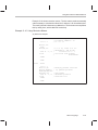
Here is a sample program listing:
2 0001
3 0002
4 0003
2f
32
x
z
.byte
.byte
.text
47
50
- In syntax descriptions, the instruction, command, or directive is in a bold
typeface font and parameters are in an italic typeface. Portions of a syntax
that are in bold should be entered as shown; portions of a syntax that are
in italics describe the type of information that should be entered. Here is
an example of command line syntax:
abs55 filename
abs55 is a command. The command invokes the absolute lister and has
one parameter, indicated by filename. When you invoke the absolute
lister, you supply the name of the file that the absolute lister uses as input.
- Square brackets ( [ and ] ) identify an optional parameter. If you use an
optional parameter, you specify the information within the brackets; you
don’t enter the brackets themselves. This is an example of a command
that has an optional parameter:
hex55 [–options] filename
The hex55 command has two parameters. The first parameter, –options,
is optional. Since options is plural, you may select several options. The
second parameter, filename, is required.
iv
Notational Conventions
- In assembler syntax statements, column 1 is reserved for the first
character of a label or symbol. If the label or symbol is optional, it is usually
not shown. If it is a required parameter, then it will be shown starting
against the left margin of the shaded box, as in the example below. No
instruction, command, directive, or parameter, other than a symbol or
label, should begin in column 1.
symbol .usect ”section name”, size in words [, blocking flag]
[, alignment flag]
The symbol is required for the .usect directive and must begin in column 1.
The section name must be enclosed in quotes and the section size in
words must be separated from the section name by a comma. The
blocking flag and alignment flag are optional and, if used, must be
separated by commas.
- Some directives can have a varying number of parameters. For example,
the .byte directive can have up to 100 parameters. The syntax for this
directive is:
.byte value1 [, ... , valuen ]
Note that .byte does not
begin in column 1.
This syntax shows that .byte must have at least one value parameter, but
you have the option of supplying additional value parameters, separated
by commas.
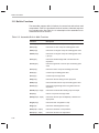
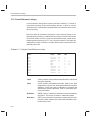
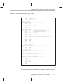
- Following are other symbols and abbreviations used throughout this
document.
Symbol
Definition
Symbol
Definition
AR0–AR7
Auxiliary Registers
0 through 7
PC
Program counter
register
B,b
Suffix — binary integer
Q,q
Suffix — octal integer
H,h
Suffix — hexadecimal
integer
SP
Stack pointer register
LSB
Least significant bit
ST
Status register
MSB
Most significant bit
Read This First
v
Related Documentation From Texas Instruments
Related Documentation From Texas Instruments
The following books describe the TMS320C55x devices and related support
tools.
TMS320C55x Optimizing C Compiler User’s Guide (literature number
SPRU281) describes the ’C55xx C compiler. This C compiler accepts
ANSI standard C source code and produces assembly language source
code for the TMS320C55x device.
TMS320C55x DSP CPU Reference Guide (SPRU371) describes the
architecture, registers, and operation of the CPU for these digital signal
processors (DSPs). This book also describes how to make individual
portions of the DSP inactive to save power.
TMS320C55x DSP Mnemonic Instruction Set Reference Guide
(SPRU374) describes the TMS320C55x digital signal processor
mnemonic instructions individually. This book also includes a summary
of the instruction set, a list of instruction opcodes, and a cross–reference
to the algebraic instruction set.
TMS320C55x DSP Algebraic Instruction Set Reference Guide (SPRU375)
describes the TMS320C55x digital signal processor algebraic
instructions individually. This book also includes a summary of the
instruction set, a list of instruction opcodes, and a cross–reference to the
mnemonic instruction set.
TMS320C55x DSP Programmer’s Guide (SPRU376) describes ways to
optimize C code and assembly code for the TMS320C55x DSPs. It also
explains how to write code that uses special features and instructions of
the DSP.
Code Composer User’s Guide (literature number SPRU296) explains how to
use the Code Composer development environment to build and debug
embedded real-time DSP applications.
Trademarks
HP-UX is a trademark of Hewlett-Packard Company.
Solaris and SunOS are trademarks of Sun Microsystems, Inc.
UNIX is a registered trademark in the United States and other countries,
licensed exclusively through X/Open Company Limited.
Windows and Windows NT are registered trademarks of Microsoft
Corporation.
Motorola-S is a trademark of Motorola, Inc.
Tektronix is a trademark of Tektronix, Inc.
vi
Contents
Contents
1
Introduction . . . . . . . . . . . . . . . . . . . . . . . . . . . . . . . . . . . . . . . . . . . . . . . . . . . . . . . . . . . . . . . . . . . . . 1-1
Provides an overview of the software development tools.
1.1
1.2
2
Introduction to Common Object File Format . . . . . . . . . . . . . . . . . . . . . . . . . . . . . . . . . . . . . . . 2-1
Discusses the basic COFF concept of sections and how they can help you use the assembler
and linker more efficiently. Common object file format, or COFF, is the object file format used
by the tools.
2.1
2.2
2.3
2.4
2.5
2.6
2.7
3
Software Development Tools Overview . . . . . . . . . . . . . . . . . . . . . . . . . . . . . . . . . . . . . . . . 1-2
Tools Descriptions . . . . . . . . . . . . . . . . . . . . . . . . . . . . . . . . . . . . . . . . . . . . . . . . . . . . . . . . . . 1-3
Sections . . . . . . . . . . . . . . . . . . . . . . . . . . . . . . . . . . . . . . . . . . . . . . . . . . . . . . . . . . . . . . . . . . . 2-2
How the Assembler Handles Sections . . . . . . . . . . . . . . . . . . . . . . . . . . . . . . . . . . . . . . . . . 2-4
2.2.1 Uninitialized Sections . . . . . . . . . . . . . . . . . . . . . . . . . . . . . . . . . . . . . . . . . . . . . . . . 2-4
2.2.2 Initialized Sections . . . . . . . . . . . . . . . . . . . . . . . . . . . . . . . . . . . . . . . . . . . . . . . . . . . 2-6
2.2.3 Named Sections . . . . . . . . . . . . . . . . . . . . . . . . . . . . . . . . . . . . . . . . . . . . . . . . . . . . . 2-7
2.2.4 Subsections . . . . . . . . . . . . . . . . . . . . . . . . . . . . . . . . . . . . . . . . . . . . . . . . . . . . . . . . 2-8
2.2.5 Section Program Counters . . . . . . . . . . . . . . . . . . . . . . . . . . . . . . . . . . . . . . . . . . . . 2-8
2.2.6 An Example That Uses Sections Directives . . . . . . . . . . . . . . . . . . . . . . . . . . . . . 2-9
How the Linker Handles Sections . . . . . . . . . . . . . . . . . . . . . . . . . . . . . . . . . . . . . . . . . . . . 2-12
2.3.1 Default Memory Allocation . . . . . . . . . . . . . . . . . . . . . . . . . . . . . . . . . . . . . . . . . . . 2-13
2.3.2 Placing Sections in the Memory Map . . . . . . . . . . . . . . . . . . . . . . . . . . . . . . . . . . 2-14
Relocation . . . . . . . . . . . . . . . . . . . . . . . . . . . . . . . . . . . . . . . . . . . . . . . . . . . . . . . . . . . . . . . . 2-15
Runtime Relocation . . . . . . . . . . . . . . . . . . . . . . . . . . . . . . . . . . . . . . . . . . . . . . . . . . . . . . . . 2-17
Loading a Program . . . . . . . . . . . . . . . . . . . . . . . . . . . . . . . . . . . . . . . . . . . . . . . . . . . . . . . . 2-18
Symbols in a COFF File . . . . . . . . . . . . . . . . . . . . . . . . . . . . . . . . . . . . . . . . . . . . . . . . . . . . 2-19
2.7.1 External Symbols . . . . . . . . . . . . . . . . . . . . . . . . . . . . . . . . . . . . . . . . . . . . . . . . . . . 2-19
2.7.2 The Symbol Table . . . . . . . . . . . . . . . . . . . . . . . . . . . . . . . . . . . . . . . . . . . . . . . . . . 2-20
Assembler Description . . . . . . . . . . . . . . . . . . . . . . . . . . . . . . . . . . . . . . . . . . . . . . . . . . . . . . . . . . . 3-1
Explains how to invoke the assembler and discusses source statement format, valid constants
and expressions, and assembler output.
3.1
3.2
3.3
Assembler Overview . . . . . . . . . . . . . . . . . . . . . . . . . . . . . . . . . . . . . . . . . . . . . . . . . . . . . . . . 3-2
Assembler Development Flow . . . . . . . . . . . . . . . . . . . . . . . . . . . . . . . . . . . . . . . . . . . . . . . . 3-3
Invoking the Assembler . . . . . . . . . . . . . . . . . . . . . . . . . . . . . . . . . . . . . . . . . . . . . . . . . . . . . . 3-4
vii
Contents
3.4
3.5
3.6
3.7
3.8
3.9
3.10
3.11
3.12
3.13
4
Assembler Directives . . . . . . . . . . . . . . . . . . . . . . . . . . . . . . . . . . . . . . . . . . . . . . . . . . . . . . . . . . . . 4-1
Describes the directives according to function, and presents the directives in alphabetical order.
4.1
4.2
4.3
viii
’C55x Assembler Features . . . . . . . . . . . . . . . . . . . . . . . . . . . . . . . . . . . . . . . . . . . . . . . . . . . 3-7
3.4.1 Byte/Word Addressing . . . . . . . . . . . . . . . . . . . . . . . . . . . . . . . . . . . . . . . . . . . . . . . 3-7
3.4.2 Parallel Instruction Rules . . . . . . . . . . . . . . . . . . . . . . . . . . . . . . . . . . . . . . . . . . . . 3-10
3.4.3 Variable-Length Instruction Size Resolution . . . . . . . . . . . . . . . . . . . . . . . . . . . . 3-10
3.4.4 Memory Modes . . . . . . . . . . . . . . . . . . . . . . . . . . . . . . . . . . . . . . . . . . . . . . . . . . . . 3-11
Naming Alternate Files and Directories for Assembler Input . . . . . . . . . . . . . . . . . . . . . 3-14
3.5.1 Using the – i Assembler Option . . . . . . . . . . . . . . . . . . . . . . . . . . . . . . . . . . . . . . . 3-14
3.5.2 Using Environment Variables (C55X_A_DIR and A_DIR) . . . . . . . . . . . . . . . . 3-15
Source Statement Format . . . . . . . . . . . . . . . . . . . . . . . . . . . . . . . . . . . . . . . . . . . . . . . . . . 3-17
3.6.1 Source Statement Syntax . . . . . . . . . . . . . . . . . . . . . . . . . . . . . . . . . . . . . . . . . . . . 3-17
3.6.2 Label Field . . . . . . . . . . . . . . . . . . . . . . . . . . . . . . . . . . . . . . . . . . . . . . . . . . . . . . . . 3-18
3.6.3 Mnemonic Field . . . . . . . . . . . . . . . . . . . . . . . . . . . . . . . . . . . . . . . . . . . . . . . . . . . . 3-18
3.6.4 Operand Field . . . . . . . . . . . . . . . . . . . . . . . . . . . . . . . . . . . . . . . . . . . . . . . . . . . . . . 3-19
3.6.5 Instruction Field . . . . . . . . . . . . . . . . . . . . . . . . . . . . . . . . . . . . . . . . . . . . . . . . . . . . 3-19
3.6.6 Comment Field . . . . . . . . . . . . . . . . . . . . . . . . . . . . . . . . . . . . . . . . . . . . . . . . . . . . . 3-20
Constants . . . . . . . . . . . . . . . . . . . . . . . . . . . . . . . . . . . . . . . . . . . . . . . . . . . . . . . . . . . . . . . . 3-21
3.7.1 Binary Integers . . . . . . . . . . . . . . . . . . . . . . . . . . . . . . . . . . . . . . . . . . . . . . . . . . . . . 3-21
3.7.2 Octal Integers . . . . . . . . . . . . . . . . . . . . . . . . . . . . . . . . . . . . . . . . . . . . . . . . . . . . . . 3-21
3.7.3 Decimal Integers . . . . . . . . . . . . . . . . . . . . . . . . . . . . . . . . . . . . . . . . . . . . . . . . . . . 3-22
3.7.4 Hexadecimal Integers . . . . . . . . . . . . . . . . . . . . . . . . . . . . . . . . . . . . . . . . . . . . . . . 3-22
3.7.5 Character Constants . . . . . . . . . . . . . . . . . . . . . . . . . . . . . . . . . . . . . . . . . . . . . . . . 3-22
3.7.6 Floating-Point Constants . . . . . . . . . . . . . . . . . . . . . . . . . . . . . . . . . . . . . . . . . . . . 3-23
Character Strings . . . . . . . . . . . . . . . . . . . . . . . . . . . . . . . . . . . . . . . . . . . . . . . . . . . . . . . . . . 3-24
Symbols . . . . . . . . . . . . . . . . . . . . . . . . . . . . . . . . . . . . . . . . . . . . . . . . . . . . . . . . . . . . . . . . . . 3-25
3.9.1 Labels . . . . . . . . . . . . . . . . . . . . . . . . . . . . . . . . . . . . . . . . . . . . . . . . . . . . . . . . . . . . 3-25
3.9.2 Symbolic Constants . . . . . . . . . . . . . . . . . . . . . . . . . . . . . . . . . . . . . . . . . . . . . . . . . 3-25
3.9.3 Defining Symbolic Constants (–d Option) . . . . . . . . . . . . . . . . . . . . . . . . . . . . . . 3-26
3.9.4 Predefined Symbolic Constants . . . . . . . . . . . . . . . . . . . . . . . . . . . . . . . . . . . . . . 3-26
3.9.5 Substitution Symbols . . . . . . . . . . . . . . . . . . . . . . . . . . . . . . . . . . . . . . . . . . . . . . . . 3-26
3.9.6 Local Labels . . . . . . . . . . . . . . . . . . . . . . . . . . . . . . . . . . . . . . . . . . . . . . . . . . . . . . . 3-28
Expressions . . . . . . . . . . . . . . . . . . . . . . . . . . . . . . . . . . . . . . . . . . . . . . . . . . . . . . . . . . . . . . . 3-31
3.10.1 Operators . . . . . . . . . . . . . . . . . . . . . . . . . . . . . . . . . . . . . . . . . . . . . . . . . . . . . . . . . 3-32
3.10.2 Expression Overflow and Underflow . . . . . . . . . . . . . . . . . . . . . . . . . . . . . . . . . . 3-32
3.10.3 Well-Defined Expressions . . . . . . . . . . . . . . . . . . . . . . . . . . . . . . . . . . . . . . . . . . . 3-33
3.10.4 Conditional Expressions . . . . . . . . . . . . . . . . . . . . . . . . . . . . . . . . . . . . . . . . . . . . . 3-33
Built-in Functions . . . . . . . . . . . . . . . . . . . . . . . . . . . . . . . . . . . . . . . . . . . . . . . . . . . . . . . . . . 3-34
Source Listings . . . . . . . . . . . . . . . . . . . . . . . . . . . . . . . . . . . . . . . . . . . . . . . . . . . . . . . . . . . . 3-36
Cross-Reference Listings . . . . . . . . . . . . . . . . . . . . . . . . . . . . . . . . . . . . . . . . . . . . . . . . . . . 3-40
Directives Summary . . . . . . . . . . . . . . . . . . . . . . . . . . . . . . . . . . . . . . . . . . . . . . . . . . . . . . . . 4-2
Directives That Define Sections . . . . . . . . . . . . . . . . . . . . . . . . . . . . . . . . . . . . . . . . . . . . . . 4-8
Directives That Initialize Constants . . . . . . . . . . . . . . . . . . . . . . . . . . . . . . . . . . . . . . . . . . . 4-11
Contents
4.4
4.5
4.6
4.7
4.8
4.9
4.10
5
5.4
5.5
5.6
5.7
5.8
5.9
5.10
Using Macros . . . . . . . . . . . . . . . . . . . . . . . . . . . . . . . . . . . . . . . . . . . . . . . . . . . . . . . . . . . . . . 5-2
Defining Macros . . . . . . . . . . . . . . . . . . . . . . . . . . . . . . . . . . . . . . . . . . . . . . . . . . . . . . . . . . . . 5-3
Macro Parameters/Substitution Symbols . . . . . . . . . . . . . . . . . . . . . . . . . . . . . . . . . . . . . . . 5-6
5.3.1 Directives That Define Substitution Symbols . . . . . . . . . . . . . . . . . . . . . . . . . . . . 5-7
5.3.2 Built-In Substitution Symbol Functions . . . . . . . . . . . . . . . . . . . . . . . . . . . . . . . . . 5-8
5.3.3 Recursive Substitution Symbols . . . . . . . . . . . . . . . . . . . . . . . . . . . . . . . . . . . . . . 5-10
5.3.4 Forced Substitution . . . . . . . . . . . . . . . . . . . . . . . . . . . . . . . . . . . . . . . . . . . . . . . . . 5-11
5.3.5 Accessing Individual Characters of Subscripted Substitution Symbols . . . . . 5-12
5.3.6 Substitution Symbols as Local Variables in Macros . . . . . . . . . . . . . . . . . . . . . . 5-13
Macro Libraries . . . . . . . . . . . . . . . . . . . . . . . . . . . . . . . . . . . . . . . . . . . . . . . . . . . . . . . . . . . . 5-14
Using Conditional Assembly in Macros . . . . . . . . . . . . . . . . . . . . . . . . . . . . . . . . . . . . . . . 5-15
Using Labels in Macros . . . . . . . . . . . . . . . . . . . . . . . . . . . . . . . . . . . . . . . . . . . . . . . . . . . . . 5-17
Producing Messages in Macros . . . . . . . . . . . . . . . . . . . . . . . . . . . . . . . . . . . . . . . . . . . . . 5-19
Formatting the Output Listing . . . . . . . . . . . . . . . . . . . . . . . . . . . . . . . . . . . . . . . . . . . . . . . . 5-21
Using Recursive and Nested Macros . . . . . . . . . . . . . . . . . . . . . . . . . . . . . . . . . . . . . . . . . 5-22
Macro Directives Summary . . . . . . . . . . . . . . . . . . . . . . . . . . . . . . . . . . . . . . . . . . . . . . . . . 5-25
Running ’C54x Code on ’C55x . . . . . . . . . . . . . . . . . . . . . . . . . . . . . . . . . . . . . . . . . . . . . . . . . . . . 6-1
Describes how to assemble a ’C54x application for use on the ’C55x.
6.1
6.2
6.3
7
4-16
4-18
4-20
4-21
4-22
4-24
4-26
Macro Language . . . . . . . . . . . . . . . . . . . . . . . . . . . . . . . . . . . . . . . . . . . . . . . . . . . . . . . . . . . . . . . . 5-1
Describes macro directives, substitution symbols used as macro parameters, and how to
create macros.
5.1
5.2
5.3
6
Directives That Align the Section Program Counter . . . . . . . . . . . . . . . . . . . . . . . . . . . . .
Directives That Format the Output Listing . . . . . . . . . . . . . . . . . . . . . . . . . . . . . . . . . . . . .
Directives That Reference Other Files . . . . . . . . . . . . . . . . . . . . . . . . . . . . . . . . . . . . . . . .
Conditional Assembly Directives . . . . . . . . . . . . . . . . . . . . . . . . . . . . . . . . . . . . . . . . . . . . .
Assembly-Time Symbol Directives . . . . . . . . . . . . . . . . . . . . . . . . . . . . . . . . . . . . . . . . . . .
Miscellaneous Directives . . . . . . . . . . . . . . . . . . . . . . . . . . . . . . . . . . . . . . . . . . . . . . . . . . .
Directives Reference . . . . . . . . . . . . . . . . . . . . . . . . . . . . . . . . . . . . . . . . . . . . . . . . . . . . . . .
’C54x to ’C55x Development Flow . . . . . . . . . . . . . . . . . . . . . . . . . . . . . . . . . . . . . . . . . . . .
6.1.1 Initializing the Stack Pointers . . . . . . . . . . . . . . . . . . . . . . . . . . . . . . . . . . . . . . . . . .
6.1.2 Handling Differences in Memory Placement . . . . . . . . . . . . . . . . . . . . . . . . . . . . .
Understanding the Listing File . . . . . . . . . . . . . . . . . . . . . . . . . . . . . . . . . . . . . . . . . . . . . . . .
Handling Reserved ’C55x Names . . . . . . . . . . . . . . . . . . . . . . . . . . . . . . . . . . . . . . . . . . . . .
6-2
6-2
6-2
6-4
6-6
Migrating a ’C54x System to a ’C55x System . . . . . . . . . . . . . . . . . . . . . . . . . . . . . . . . . . . . . . 7-1
Describes system considerations when porting ’C54x code to ’C55x.
7.1
Handling Interrupts . . . . . . . . . . . . . . . . . . . . . . . . . . . . . . . . . . . . . . . . . . . . . . . . . . . . . . . . .
7.1.1 Differences in the Interrupt Vector Table . . . . . . . . . . . . . . . . . . . . . . . . . . . . . . . .
7.1.2 Handling Interrupt Service Routines . . . . . . . . . . . . . . . . . . . . . . . . . . . . . . . . . . . .
7.1.3 Other Issues Related to Interrupts . . . . . . . . . . . . . . . . . . . . . . . . . . . . . . . . . . . . .
Contents
7-2
7-2
7-3
7-4
ix
Contents
7.2
7.3
7.4
8
Archiver Description . . . . . . . . . . . . . . . . . . . . . . . . . . . . . . . . . . . . . . . . . . . . . . . . . . . . . . . . . . . . . 8-1
Contains instructions for invoking the archiver, creating new archive libraries, and modifying
existing libraries.
8.1
8.2
8.3
8.4
9
Archiver Overview . . . . . . . . . . . . . . . . . . . . . . . . . . . . . . . . . . . . . . . . . . . . . . . . . . . . . . . . . .
Archiver Development Flow . . . . . . . . . . . . . . . . . . . . . . . . . . . . . . . . . . . . . . . . . . . . . . . . . .
Invoking the Archiver . . . . . . . . . . . . . . . . . . . . . . . . . . . . . . . . . . . . . . . . . . . . . . . . . . . . . . . .
Archiver Examples . . . . . . . . . . . . . . . . . . . . . . . . . . . . . . . . . . . . . . . . . . . . . . . . . . . . . . . . . .
8-2
8-3
8-4
8-6
Linker Description . . . . . . . . . . . . . . . . . . . . . . . . . . . . . . . . . . . . . . . . . . . . . . . . . . . . . . . . . . . . . . . 9-1
Explains how to invoke the linker, provides details about linker operation, discusses linker
directives, and presents a detailed linking example.
9.1
9.2
9.3
9.4
x
Using Ported ’C54x Functions with Native ’C55x Functions . . . . . . . . . . . . . . . . . . . . . . . 7-5
7.2.1 Runtime Environment for Ported ’C54x Code . . . . . . . . . . . . . . . . . . . . . . . . . . . . 7-5
7.2.2 ’C55x Registers Used as Temporaries . . . . . . . . . . . . . . . . . . . . . . . . . . . . . . . . . . 7-6
7.2.3 ’C54x to ’C55x Register Mapping . . . . . . . . . . . . . . . . . . . . . . . . . . . . . . . . . . . . . . 7-6
7.2.4 Status Bit Field Mapping . . . . . . . . . . . . . . . . . . . . . . . . . . . . . . . . . . . . . . . . . . . . . . 7-7
7.2.5 Switching Between Runtime Environments . . . . . . . . . . . . . . . . . . . . . . . . . . . . . 7-9
7.2.6 Example of C Code Calling ’C54x Assembly . . . . . . . . . . . . . . . . . . . . . . . . . . . 7-10
7.2.7 Example of ’C54x Assembly Calling C Code . . . . . . . . . . . . . . . . . . . . . . . . . . . 7-14
Non-Portable ’C54x Coding Practices . . . . . . . . . . . . . . . . . . . . . . . . . . . . . . . . . . . . . . . . 7-17
Additional ’C54x Issues . . . . . . . . . . . . . . . . . . . . . . . . . . . . . . . . . . . . . . . . . . . . . . . . . . . . . 7-19
Linker Overview . . . . . . . . . . . . . . . . . . . . . . . . . . . . . . . . . . . . . . . . . . . . . . . . . . . . . . . . . . . . 9-2
Linker Development Flow . . . . . . . . . . . . . . . . . . . . . . . . . . . . . . . . . . . . . . . . . . . . . . . . . . . . 9-3
Invoking the Linker . . . . . . . . . . . . . . . . . . . . . . . . . . . . . . . . . . . . . . . . . . . . . . . . . . . . . . . . . . 9-4
Linker Options . . . . . . . . . . . . . . . . . . . . . . . . . . . . . . . . . . . . . . . . . . . . . . . . . . . . . . . . . . . . . 9-6
9.4.1 Relocation Capabilities (– a and – r Options) . . . . . . . . . . . . . . . . . . . . . . . . . . . . . 9-8
9.4.2 Disable Merge of Symbolic Debugging Information (–b Option) . . . . . . . . . . . 9-10
9.4.3 C Language Options (–c and –cr Options) . . . . . . . . . . . . . . . . . . . . . . . . . . . . . 9-10
9.4.4 Define an Entry Point (–e global_symbol Option) . . . . . . . . . . . . . . . . . . . . . . . 9-11
9.4.5 Set Default Fill Value (–f cc Option) . . . . . . . . . . . . . . . . . . . . . . . . . . . . . . . . . . . 9-11
9.4.6 Make a Symbol Global (–g global_symbol Option) . . . . . . . . . . . . . . . . . . . . . . 9-12
9.4.7 Make All Global Symbols Static (–h Option) . . . . . . . . . . . . . . . . . . . . . . . . . . . . 9-12
9.4.8 Define Heap Size (–heap constant Option) . . . . . . . . . . . . . . . . . . . . . . . . . . . . . 9-12
9.4.9 Alter the Library Search Algorithm (–l Option, –i Option, and
C55X_C_DIR/C_DIR Environment Variables) . . . . . . . . . . . . . . . . . . . . . . . . . . 9-13
9.4.10 Ignore Alignment Flags (–k Option) . . . . . . . . . . . . . . . . . . . . . . . . . . . . . . . . . . . 9-16
9.4.11 Create a Map File (–m filename Option) . . . . . . . . . . . . . . . . . . . . . . . . . . . . . . . 9-16
9.4.12 Name an Output Module (–o filename Option) . . . . . . . . . . . . . . . . . . . . . . . . . . 9-17
9.4.13 Specify a Quiet Run (–q Option) . . . . . . . . . . . . . . . . . . . . . . . . . . . . . . . . . . . . . . 9-17
9.4.14 Strip Symbolic Information (–s Option) . . . . . . . . . . . . . . . . . . . . . . . . . . . . . . . . 9-17
9.4.15 Define Stack Size (–stack constant Option) . . . . . . . . . . . . . . . . . . . . . . . . . . . . 9-18
9.4.16 Define Secondary Stack Size (–sysstack constant Option) . . . . . . . . . . . . . . . 9-18
9.4.17 Introduce an Unresolved Symbol (–u symbol Option) . . . . . . . . . . . . . . . . . . . . 9-18
Contents
9.5
9.6
9.7
9.8
9.9
9.10
9.11
9.12
9.13
9.14
9.15
9.16
9.17
9.18
9.4.18 Display a Message for Output Section Information (–w Option) . . . . . . . . . . .
9.4.19 Exhaustively Read Libraries (–x Option) . . . . . . . . . . . . . . . . . . . . . . . . . . . . . . .
Byte/Word Addressing . . . . . . . . . . . . . . . . . . . . . . . . . . . . . . . . . . . . . . . . . . . . . . . . . . . . . .
Linker Command Files . . . . . . . . . . . . . . . . . . . . . . . . . . . . . . . . . . . . . . . . . . . . . . . . . . . . .
9.6.1 Reserved Names in Linker Command Files . . . . . . . . . . . . . . . . . . . . . . . . . . . .
9.6.2 Constants in Command Files . . . . . . . . . . . . . . . . . . . . . . . . . . . . . . . . . . . . . . . . .
Object Libraries . . . . . . . . . . . . . . . . . . . . . . . . . . . . . . . . . . . . . . . . . . . . . . . . . . . . . . . . . . .
The MEMORY Directive . . . . . . . . . . . . . . . . . . . . . . . . . . . . . . . . . . . . . . . . . . . . . . . . . . . .
9.8.1 Default Memory Model . . . . . . . . . . . . . . . . . . . . . . . . . . . . . . . . . . . . . . . . . . . . . .
9.8.2 MEMORY Directive Syntax . . . . . . . . . . . . . . . . . . . . . . . . . . . . . . . . . . . . . . . . . .
The SECTIONS Directive . . . . . . . . . . . . . . . . . . . . . . . . . . . . . . . . . . . . . . . . . . . . . . . . . . .
9.9.1 Default Configuration . . . . . . . . . . . . . . . . . . . . . . . . . . . . . . . . . . . . . . . . . . . . . . .
9.9.2 SECTIONS Directive Syntax . . . . . . . . . . . . . . . . . . . . . . . . . . . . . . . . . . . . . . . . .
9.9.3 Allocation . . . . . . . . . . . . . . . . . . . . . . . . . . . . . . . . . . . . . . . . . . . . . . . . . . . . . . . . . .
Specifying a Section’s Runtime Address . . . . . . . . . . . . . . . . . . . . . . . . . . . . . . . . . . . . . .
9.10.1 Specifying Load and Run Addresses . . . . . . . . . . . . . . . . . . . . . . . . . . . . . . . . . .
9.10.2 Uninitialized Sections . . . . . . . . . . . . . . . . . . . . . . . . . . . . . . . . . . . . . . . . . . . . . . .
9.10.3 Referring to the Load Address by Using the .label Directive . . . . . . . . . . . . . .
Using UNION and GROUP Statements . . . . . . . . . . . . . . . . . . . . . . . . . . . . . . . . . . . . . . .
9.11.1 Overlaying Sections With the UNION Statement . . . . . . . . . . . . . . . . . . . . . . . .
9.11.2 Grouping Output Sections Together . . . . . . . . . . . . . . . . . . . . . . . . . . . . . . . . . . .
9.11.3 Nesting UNIONs and GROUPs . . . . . . . . . . . . . . . . . . . . . . . . . . . . . . . . . . . . . . .
9.11.4 Checking the Consistency of Allocators . . . . . . . . . . . . . . . . . . . . . . . . . . . . . . .
Overlay Pages . . . . . . . . . . . . . . . . . . . . . . . . . . . . . . . . . . . . . . . . . . . . . . . . . . . . . . . . . . . .
9.12.1 Using the MEMORY Directive to Define Overlay Pages . . . . . . . . . . . . . . . . . .
9.12.2 Using Overlay Pages With the SECTIONS Directive . . . . . . . . . . . . . . . . . . . .
9.12.3 Page Definition Syntax . . . . . . . . . . . . . . . . . . . . . . . . . . . . . . . . . . . . . . . . . . . . . .
Default Allocation Algorithm . . . . . . . . . . . . . . . . . . . . . . . . . . . . . . . . . . . . . . . . . . . . . . . . .
9.13.1 Allocation Algorithm . . . . . . . . . . . . . . . . . . . . . . . . . . . . . . . . . . . . . . . . . . . . . . . . .
9.13.2 General Rules for Output Sections . . . . . . . . . . . . . . . . . . . . . . . . . . . . . . . . . . . .
Special Section Types (DSECT, COPY, and NOLOAD) . . . . . . . . . . . . . . . . . . . . . . . . .
Assigning Symbols at Link Time . . . . . . . . . . . . . . . . . . . . . . . . . . . . . . . . . . . . . . . . . . . . .
9.15.1 Syntax of Assignment Statements . . . . . . . . . . . . . . . . . . . . . . . . . . . . . . . . . . . .
9.15.2 Assigning the SPC to a Symbol . . . . . . . . . . . . . . . . . . . . . . . . . . . . . . . . . . . . . .
9.15.3 Assignment Expressions . . . . . . . . . . . . . . . . . . . . . . . . . . . . . . . . . . . . . . . . . . . .
9.15.4 Symbols Defined by the Linker . . . . . . . . . . . . . . . . . . . . . . . . . . . . . . . . . . . . . . .
9.15.5 Symbols Defined Only For C Support (–c or –cr Option) . . . . . . . . . . . . . . . . .
Creating and Filling Holes . . . . . . . . . . . . . . . . . . . . . . . . . . . . . . . . . . . . . . . . . . . . . . . . . .
9.16.1 Initialized and Uninitialized Sections . . . . . . . . . . . . . . . . . . . . . . . . . . . . . . . . . .
9.16.2 Creating Holes . . . . . . . . . . . . . . . . . . . . . . . . . . . . . . . . . . . . . . . . . . . . . . . . . . . . .
9.16.3 Filling Holes . . . . . . . . . . . . . . . . . . . . . . . . . . . . . . . . . . . . . . . . . . . . . . . . . . . . . . .
9.16.4 Explicit Initialization of Uninitialized Sections . . . . . . . . . . . . . . . . . . . . . . . . . . .
Partial (Incremental) Linking . . . . . . . . . . . . . . . . . . . . . . . . . . . . . . . . . . . . . . . . . . . . . . . .
Linking C Code . . . . . . . . . . . . . . . . . . . . . . . . . . . . . . . . . . . . . . . . . . . . . . . . . . . . . . . . . . . .
Contents
9-19
9-20
9-21
9-22
9-25
9-25
9-26
9-28
9-28
9-28
9-32
9-32
9-32
9-35
9-41
9-41
9-42
9-42
9-45
9-45
9-47
9-48
9-49
9-50
9-50
9-52
9-53
9-55
9-55
9-56
9-58
9-59
9-59
9-60
9-60
9-62
9-62
9-63
9-63
9-63
9-65
9-66
9-67
9-69
xi
Contents
9.19
9.18.1 Runtime Initialization . . . . . . . . . . . . . . . . . . . . . . . . . . . . . . . . . . . . . . . . . . . . . . . .
9.18.2 Object Libraries and Runtime Support . . . . . . . . . . . . . . . . . . . . . . . . . . . . . . . . .
9.18.3 Setting the Size of the Stack and Heap Sections . . . . . . . . . . . . . . . . . . . . . . . .
9.18.4 Autoinitialization (ROM and RAM Models) . . . . . . . . . . . . . . . . . . . . . . . . . . . . .
9.18.5 The –c and –cr Linker Options . . . . . . . . . . . . . . . . . . . . . . . . . . . . . . . . . . . . . . .
Linker Example . . . . . . . . . . . . . . . . . . . . . . . . . . . . . . . . . . . . . . . . . . . . . . . . . . . . . . . . . . . .
9-69
9-69
9-70
9-70
9-72
9-73
10 Absolute Lister Description . . . . . . . . . . . . . . . . . . . . . . . . . . . . . . . . . . . . . . . . . . . . . . . . . . . . . 10-1
Explains how to invoke the absolute lister to obtain a listing of the absolute addresses of an
object file.
10.1
10.2
10.3
Producing an Absolute Listing . . . . . . . . . . . . . . . . . . . . . . . . . . . . . . . . . . . . . . . . . . . . . . . 10-2
Invoking the Absolute Lister . . . . . . . . . . . . . . . . . . . . . . . . . . . . . . . . . . . . . . . . . . . . . . . . . 10-3
Absolute Lister Example . . . . . . . . . . . . . . . . . . . . . . . . . . . . . . . . . . . . . . . . . . . . . . . . . . . . 10-5
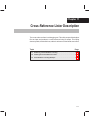
11 Cross-Reference Lister Description . . . . . . . . . . . . . . . . . . . . . . . . . . . . . . . . . . . . . . . . . . . . . . 11-1
Explains how to invoke the cross-reference lister to obtain a listing of symbols, their definitions,
and their references in the linked source files.
11.1
11.2
11.3
Producing a Cross-Reference Listing . . . . . . . . . . . . . . . . . . . . . . . . . . . . . . . . . . . . . . . . . 11-2
Invoking the Cross-Reference Lister . . . . . . . . . . . . . . . . . . . . . . . . . . . . . . . . . . . . . . . . . 11-3
Cross-Reference Listing Example . . . . . . . . . . . . . . . . . . . . . . . . . . . . . . . . . . . . . . . . . . . . 11-4
12 Disassembler Description . . . . . . . . . . . . . . . . . . . . . . . . . . . . . . . . . . . . . . . . . . . . . . . . . . . . . . . 12-1
Explains how to invoke the disassembler to obtain a listing of the COFF disassembly for object
files or linked executable files.
12.1
12.2
Invoking the Disassembler . . . . . . . . . . . . . . . . . . . . . . . . . . . . . . . . . . . . . . . . . . . . . . . . . . 12-2
Disassembly Examples . . . . . . . . . . . . . . . . . . . . . . . . . . . . . . . . . . . . . . . . . . . . . . . . . . . . . 12-4
13 Hex Conversion Utility Description . . . . . . . . . . . . . . . . . . . . . . . . . . . . . . . . . . . . . . . . . . . . . . 13-1
Explains how to invoke the hex utility to convert a COFF object file into one of several standard
hexadecimal formats suitable for loading into an EPROM programmer.
13.1
13.2
13.3
13.4
xii
Hex Conversion Utility Development Flow . . . . . . . . . . . . . . . . . . . . . . . . . . . . . . . . . . . . . 13-2
Invoking the Hex Conversion Utility . . . . . . . . . . . . . . . . . . . . . . . . . . . . . . . . . . . . . . . . . . 13-3
Command File . . . . . . . . . . . . . . . . . . . . . . . . . . . . . . . . . . . . . . . . . . . . . . . . . . . . . . . . . . . . 13-6
13.3.1 Examples of Command Files . . . . . . . . . . . . . . . . . . . . . . . . . . . . . . . . . . . . . . . . . 13-7
Understanding Memory Widths . . . . . . . . . . . . . . . . . . . . . . . . . . . . . . . . . . . . . . . . . . . . . . 13-8
13.4.1 Target Width . . . . . . . . . . . . . . . . . . . . . . . . . . . . . . . . . . . . . . . . . . . . . . . . . . . . . . . 13-9
13.4.2 Data Width . . . . . . . . . . . . . . . . . . . . . . . . . . . . . . . . . . . . . . . . . . . . . . . . . . . . . . . . 13-9
13.4.3 Memory Width . . . . . . . . . . . . . . . . . . . . . . . . . . . . . . . . . . . . . . . . . . . . . . . . . . . . . 13-9
13.4.4 ROM Width . . . . . . . . . . . . . . . . . . . . . . . . . . . . . . . . . . . . . . . . . . . . . . . . . . . . . . . 13-10
13.4.5 A Memory Configuration Example . . . . . . . . . . . . . . . . . . . . . . . . . . . . . . . . . . . 13-13
13.4.6 Specifying Word Order for Output Words . . . . . . . . . . . . . . . . . . . . . . . . . . . . . 13-13
Contents
13.5
The ROMS Directive . . . . . . . . . . . . . . . . . . . . . . . . . . . . . . . . . . . . . . . . . . . . . . . . . . . . . .
13.5.1 When to Use the ROMS Directive . . . . . . . . . . . . . . . . . . . . . . . . . . . . . . . . . . .
13.5.2 An Example of the ROMS Directive . . . . . . . . . . . . . . . . . . . . . . . . . . . . . . . . . .
13.5.3 Creating a Map File of the ROMS Directive . . . . . . . . . . . . . . . . . . . . . . . . . . .
13.6 The SECTIONS Directive . . . . . . . . . . . . . . . . . . . . . . . . . . . . . . . . . . . . . . . . . . . . . . . . . .
13.7 Output Filenames . . . . . . . . . . . . . . . . . . . . . . . . . . . . . . . . . . . . . . . . . . . . . . . . . . . . . . . . .
13.7.1 Assigning Output Filenames . . . . . . . . . . . . . . . . . . . . . . . . . . . . . . . . . . . . . . . .
13.8 Image Mode and the –fill Option . . . . . . . . . . . . . . . . . . . . . . . . . . . . . . . . . . . . . . . . . . . .
13.8.1 The –image Option . . . . . . . . . . . . . . . . . . . . . . . . . . . . . . . . . . . . . . . . . . . . . . . .
13.8.2 Specifying a Fill Value . . . . . . . . . . . . . . . . . . . . . . . . . . . . . . . . . . . . . . . . . . . . . .
13.8.3 Steps to Follow in Image Mode . . . . . . . . . . . . . . . . . . . . . . . . . . . . . . . . . . . . . .
13.9 Building a Table for an On-Chip Boot Loader . . . . . . . . . . . . . . . . . . . . . . . . . . . . . . . . .
13.9.1 Description of the Boot Table . . . . . . . . . . . . . . . . . . . . . . . . . . . . . . . . . . . . . . . .
13.9.2 The Boot Table Format . . . . . . . . . . . . . . . . . . . . . . . . . . . . . . . . . . . . . . . . . . . . .
13.9.3 How to Build the Boot Table . . . . . . . . . . . . . . . . . . . . . . . . . . . . . . . . . . . . . . . . .
13.9.4 Booting From a Device Peripheral . . . . . . . . . . . . . . . . . . . . . . . . . . . . . . . . . . .
13.9.5 Setting the Entry Point for the Boot Table . . . . . . . . . . . . . . . . . . . . . . . . . . . . .
13.9.6 Using the ’C55x Boot Loader . . . . . . . . . . . . . . . . . . . . . . . . . . . . . . . . . . . . . . . .
13.10 Controlling the ROM Device Address . . . . . . . . . . . . . . . . . . . . . . . . . . . . . . . . . . . . . . . .
13.10.1 Controlling the Starting Address . . . . . . . . . . . . . . . . . . . . . . . . . . . . . . . . . . . . .
13.10.2 Controlling the Address Increment Index . . . . . . . . . . . . . . . . . . . . . . . . . . . . .
13.10.3 The –byte Option . . . . . . . . . . . . . . . . . . . . . . . . . . . . . . . . . . . . . . . . . . . . . . . . . .
13.10.4 Dealing With Address Holes . . . . . . . . . . . . . . . . . . . . . . . . . . . . . . . . . . . . . . . .
13.11 Description of the Object Formats . . . . . . . . . . . . . . . . . . . . . . . . . . . . . . . . . . . . . . . . . . .
13.11.1 ASCII-Hex Object Format (–a Option) . . . . . . . . . . . . . . . . . . . . . . . . . . . . . . . .
13.11.2 Intel MCS-86 Object Format (–i Option) . . . . . . . . . . . . . . . . . . . . . . . . . . . . . .
13.11.3 Motorola Exorciser Object Format (–m1, –m2, –m3 Options) . . . . . . . . . . . .
13.11.4 Texas Instruments SDSMAC Object Format (–t Option) . . . . . . . . . . . . . . . . .
13.11.5 Extended Tektronix Object Format (–x Option) . . . . . . . . . . . . . . . . . . . . . . . .
13.12 Hex Conversion Utility Error Messages . . . . . . . . . . . . . . . . . . . . . . . . . . . . . . . . . . . . . .
A
13-15
13-17
13-18
13-20
13-21
13-23
13-23
13-25
13-25
13-26
13-26
13-27
13-27
13-27
13-28
13-30
13-31
13-31
13-33
13-33
13-35
13-35
13-36
13-37
13-38
13-39
13-40
13-41
13-42
13-43
Common Object File Format . . . . . . . . . . . . . . . . . . . . . . . . . . . . . . . . . . . . . . . . . . . . . . . . . . . . . . A-1
Contains supplemental technical data about the internal format and structure of COFF object
files.
A.1
A.2
A.3
A.4
A.5
A.6
A.7
COFF File Structure . . . . . . . . . . . . . . . . . . . . . . . . . . . . . . . . . . . . . . . . . . . . . . . . . . . . . . . . A-2
File Header Structure . . . . . . . . . . . . . . . . . . . . . . . . . . . . . . . . . . . . . . . . . . . . . . . . . . . . . . . A-4
Optional File Header Format . . . . . . . . . . . . . . . . . . . . . . . . . . . . . . . . . . . . . . . . . . . . . . . . . A-5
Section Header Structure . . . . . . . . . . . . . . . . . . . . . . . . . . . . . . . . . . . . . . . . . . . . . . . . . . . . A-6
Structuring Relocation Information . . . . . . . . . . . . . . . . . . . . . . . . . . . . . . . . . . . . . . . . . . . . A-9
Line-Number Table Structure . . . . . . . . . . . . . . . . . . . . . . . . . . . . . . . . . . . . . . . . . . . . . . . . A-11
Symbol Table Structure and Content . . . . . . . . . . . . . . . . . . . . . . . . . . . . . . . . . . . . . . . . . A-13
A.7.1 Special Symbols . . . . . . . . . . . . . . . . . . . . . . . . . . . . . . . . . . . . . . . . . . . . . . . . . . . A-15
A.7.2 Symbol Name Format . . . . . . . . . . . . . . . . . . . . . . . . . . . . . . . . . . . . . . . . . . . . . . . A-17
A.7.3 String Table Structure . . . . . . . . . . . . . . . . . . . . . . . . . . . . . . . . . . . . . . . . . . . . . . . A-17
Contents
xiii
Contents
A.7.4
A.7.5
A.7.6
A.7.7
A.7.8
Storage Classes . . . . . . . . . . . . . . . . . . . . . . . . . . . . . . . . . . . . . . . . . . . . . . . . . . . .
Symbol Values . . . . . . . . . . . . . . . . . . . . . . . . . . . . . . . . . . . . . . . . . . . . . . . . . . . . .
Section Number . . . . . . . . . . . . . . . . . . . . . . . . . . . . . . . . . . . . . . . . . . . . . . . . . . . .
Type Entry . . . . . . . . . . . . . . . . . . . . . . . . . . . . . . . . . . . . . . . . . . . . . . . . . . . . . . . . .
Auxiliary Entries . . . . . . . . . . . . . . . . . . . . . . . . . . . . . . . . . . . . . . . . . . . . . . . . . . . .
A-18
A-19
A-20
A-20
A-22
B
Symbolic Debugging Directives . . . . . . . . . . . . . . . . . . . . . . . . . . . . . . . . . . . . . . . . . . . . . . . . . . B-1
Discusses symbolic debugging directives that the C compiler uses.
C
Assembler Error Messages . . . . . . . . . . . . . . . . . . . . . . . . . . . . . . . . . . . . . . . . . . . . . . . . . . . . . . . C-1
Lists the error messages that the assembler and linker issue, and gives a description of the
condition(s) that caused each error.
D
Linker Error Messages . . . . . . . . . . . . . . . . . . . . . . . . . . . . . . . . . . . . . . . . . . . . . . . . . . . . . . . . . . . D-1
Lists the error messages that the assembler and linker issue, and gives a description of the
condition(s) that caused each error.
E
Glossary . . . . . . . . . . . . . . . . . . . . . . . . . . . . . . . . . . . . . . . . . . . . . . . . . . . . . . . . . . . . . . . . . . . . . . . . E-1
Defines terms and acronyms used in this book.
xiv
Figures
Figures
1–1
2–1
2–2
2–3
3–1
4–1
4–2
4–3
4–4
4–5
4–6
4–7
7–1
8–1
9–1
9–2
9–3
9–4
9–5
9–6
9–7
10–1
10–2
10–3
11–1
13–1
13–2
13–3
13–4
13–5
13–6
13–7
13–8
13–9
13–10
13–11
TMS320C55x Software Development Flow . . . . . . . . . . . . . . . . . . . . . . . . . . . . . . . . . . . . . . . 1-2
Partitioning Memory Into Logical Blocks . . . . . . . . . . . . . . . . . . . . . . . . . . . . . . . . . . . . . . . . . . 2-3
Object Code Generated by the File in Example 2–1 . . . . . . . . . . . . . . . . . . . . . . . . . . . . . . 2-11
Combining Input Sections to Form an Executable Object Module . . . . . . . . . . . . . . . . . . . 2-13
Assembler Development Flow . . . . . . . . . . . . . . . . . . . . . . . . . . . . . . . . . . . . . . . . . . . . . . . . . . 3-3
The .space and .bes Directives . . . . . . . . . . . . . . . . . . . . . . . . . . . . . . . . . . . . . . . . . . . . . . . . 4-12
The .field Directive . . . . . . . . . . . . . . . . . . . . . . . . . . . . . . . . . . . . . . . . . . . . . . . . . . . . . . . . . . . 4-13
Initialization Directives . . . . . . . . . . . . . . . . . . . . . . . . . . . . . . . . . . . . . . . . . . . . . . . . . . . . . . . . 4-15
The .align Directive . . . . . . . . . . . . . . . . . . . . . . . . . . . . . . . . . . . . . . . . . . . . . . . . . . . . . . . . . . . 4-17
Allocating .bss Blocks Within a Page . . . . . . . . . . . . . . . . . . . . . . . . . . . . . . . . . . . . . . . . . . . 4-32
The .field Directive . . . . . . . . . . . . . . . . . . . . . . . . . . . . . . . . . . . . . . . . . . . . . . . . . . . . . . . . . . . 4-52
The .usect Directive . . . . . . . . . . . . . . . . . . . . . . . . . . . . . . . . . . . . . . . . . . . . . . . . . . . . . . . . . 4-105
Runtime Environments for Ported ’C54x Code and Native ’C55x Code . . . . . . . . . . . . . . . 7-9
Archiver Development Flow . . . . . . . . . . . . . . . . . . . . . . . . . . . . . . . . . . . . . . . . . . . . . . . . . . . . 8-3
Linker Development Flow . . . . . . . . . . . . . . . . . . . . . . . . . . . . . . . . . . . . . . . . . . . . . . . . . . . . . . 9-3
Section Allocation Defined by Example 9–4 . . . . . . . . . . . . . . . . . . . . . . . . . . . . . . . . . . . . . . 9-34
Runtime Execution of Example 9–6 . . . . . . . . . . . . . . . . . . . . . . . . . . . . . . . . . . . . . . . . . . . . . 9-44
Memory Allocation Shown in Example 9–7 and Example 9–8 . . . . . . . . . . . . . . . . . . . . . . 9-46
Overlay Pages Defined by Example 9–11 and Example 9–12 . . . . . . . . . . . . . . . . . . . . . . 9-51
RAM Model of Autoinitialization . . . . . . . . . . . . . . . . . . . . . . . . . . . . . . . . . . . . . . . . . . . . . . . . 9-71
ROM Model of Autoinitialization . . . . . . . . . . . . . . . . . . . . . . . . . . . . . . . . . . . . . . . . . . . . . . . . 9-71
Absolute Lister Development Flow . . . . . . . . . . . . . . . . . . . . . . . . . . . . . . . . . . . . . . . . . . . . . 10-2
module1.lst . . . . . . . . . . . . . . . . . . . . . . . . . . . . . . . . . . . . . . . . . . . . . . . . . . . . . . . . . . . . . . . . . . 10-9
module2.lst . . . . . . . . . . . . . . . . . . . . . . . . . . . . . . . . . . . . . . . . . . . . . . . . . . . . . . . . . . . . . . . . . . 10-9
Cross-Reference Lister Development Flow . . . . . . . . . . . . . . . . . . . . . . . . . . . . . . . . . . . . . . 11-2
Hex Conversion Utility Development Flow . . . . . . . . . . . . . . . . . . . . . . . . . . . . . . . . . . . . . . . 13-2
Hex Conversion Utility Process Flow . . . . . . . . . . . . . . . . . . . . . . . . . . . . . . . . . . . . . . . . . . . . 13-8
Data and Memory Widths . . . . . . . . . . . . . . . . . . . . . . . . . . . . . . . . . . . . . . . . . . . . . . . . . . . . 13-10
Data, Memory, and ROM Widths . . . . . . . . . . . . . . . . . . . . . . . . . . . . . . . . . . . . . . . . . . . . . . 13-12
’C55x Memory Configuration Example . . . . . . . . . . . . . . . . . . . . . . . . . . . . . . . . . . . . . . . . . 13-13
Varying the Word Order . . . . . . . . . . . . . . . . . . . . . . . . . . . . . . . . . . . . . . . . . . . . . . . . . . . . . . 13-14
The infile.out File From Example 13–1 Partitioned Into Four Output Files . . . . . . . . . . . 13-19
Sample Command File for Booting From a ’C55x EPROM . . . . . . . . . . . . . . . . . . . . . . . . 13-32
Hex Command File for Avoiding a Hole at the Beginning of a Section . . . . . . . . . . . . . . 13-36
ASCII-Hex Object Format . . . . . . . . . . . . . . . . . . . . . . . . . . . . . . . . . . . . . . . . . . . . . . . . . . . . 13-38
Intel Hex Object Format . . . . . . . . . . . . . . . . . . . . . . . . . . . . . . . . . . . . . . . . . . . . . . . . . . . . . . 13-39
Contents
xv
Contents
13–12
13–13
13–14
A–1
A–2
A–3
A–4
A–5
A–6
A–7
A–8
A–9
xvi
Motorola-S Format . . . . . . . . . . . . . . . . . . . . . . . . . . . . . . . . . . . . . . . . . . . . . . . . . . . . . . . . . . 13-40
TI-Tagged Object Format . . . . . . . . . . . . . . . . . . . . . . . . . . . . . . . . . . . . . . . . . . . . . . . . . . . . . 13-41
Extended Tektronix Object Format . . . . . . . . . . . . . . . . . . . . . . . . . . . . . . . . . . . . . . . . . . . . . 13-42
COFF File Structure . . . . . . . . . . . . . . . . . . . . . . . . . . . . . . . . . . . . . . . . . . . . . . . . . . . . . . . . . . . A-2
COFF Object File . . . . . . . . . . . . . . . . . . . . . . . . . . . . . . . . . . . . . . . . . . . . . . . . . . . . . . . . . . . . . A-3
Section Header Pointers for the .text Section . . . . . . . . . . . . . . . . . . . . . . . . . . . . . . . . . . . . . A-8
Line-Number Blocks . . . . . . . . . . . . . . . . . . . . . . . . . . . . . . . . . . . . . . . . . . . . . . . . . . . . . . . . . . A-11
Line-Number Entries . . . . . . . . . . . . . . . . . . . . . . . . . . . . . . . . . . . . . . . . . . . . . . . . . . . . . . . . . A-12
Symbol Table Contents . . . . . . . . . . . . . . . . . . . . . . . . . . . . . . . . . . . . . . . . . . . . . . . . . . . . . . . A-13
Symbols for Blocks . . . . . . . . . . . . . . . . . . . . . . . . . . . . . . . . . . . . . . . . . . . . . . . . . . . . . . . . . . . A-16
Symbols for Functions . . . . . . . . . . . . . . . . . . . . . . . . . . . . . . . . . . . . . . . . . . . . . . . . . . . . . . . . A-16
String Table . . . . . . . . . . . . . . . . . . . . . . . . . . . . . . . . . . . . . . . . . . . . . . . . . . . . . . . . . . . . . . . . . A-17
Tables
Tables
3–1
3–2
3–3
4–1
4–2
5–1
5–2
5–3
5–4
5–5
5–6
9–1
11–1
13–1
13–2
13–3
A–1
A–2
A–3
A–4
A–5
A–6
A–7
A–8
A–9
A–10
A–11
A–12
A–13
A–14
A–15
A–16
A–17
A–18
A–19
A–20
Operators Used in Expressions (Precedence) . . . . . . . . . . . . . . . . . . . . . . . . . . . . . . . . . . . . 3-32
Assembler Built-In Math Functions . . . . . . . . . . . . . . . . . . . . . . . . . . . . . . . . . . . . . . . . . . . . . 3-34
Symbol Attributes . . . . . . . . . . . . . . . . . . . . . . . . . . . . . . . . . . . . . . . . . . . . . . . . . . . . . . . . . . . . 3-41
Assembler Directives Summary . . . . . . . . . . . . . . . . . . . . . . . . . . . . . . . . . . . . . . . . . . . . . . . . . 4-2
Memory-Mapped Registers . . . . . . . . . . . . . . . . . . . . . . . . . . . . . . . . . . . . . . . . . . . . . . . . . . . . 4-76
Functions and Return Values . . . . . . . . . . . . . . . . . . . . . . . . . . . . . . . . . . . . . . . . . . . . . . . . . . . 5-9
Creating Macros . . . . . . . . . . . . . . . . . . . . . . . . . . . . . . . . . . . . . . . . . . . . . . . . . . . . . . . . . . . . . 5-25
Manipulating Substitution Symbols . . . . . . . . . . . . . . . . . . . . . . . . . . . . . . . . . . . . . . . . . . . . . 5-25
Conditional Assembly . . . . . . . . . . . . . . . . . . . . . . . . . . . . . . . . . . . . . . . . . . . . . . . . . . . . . . . . . 5-25
Producing Assembly-Time Messages . . . . . . . . . . . . . . . . . . . . . . . . . . . . . . . . . . . . . . . . . . . 5-26
Formatting the Listing . . . . . . . . . . . . . . . . . . . . . . . . . . . . . . . . . . . . . . . . . . . . . . . . . . . . . . . . . 5-26
Operators Used in Expressions (Precedence) . . . . . . . . . . . . . . . . . . . . . . . . . . . . . . . . . . . . 9-61
Symbol Attributes . . . . . . . . . . . . . . . . . . . . . . . . . . . . . . . . . . . . . . . . . . . . . . . . . . . . . . . . . . . . 11-6
Hex Conversion Utility Options . . . . . . . . . . . . . . . . . . . . . . . . . . . . . . . . . . . . . . . . . . . . . . . . . 13-4
Boot-Loader Options . . . . . . . . . . . . . . . . . . . . . . . . . . . . . . . . . . . . . . . . . . . . . . . . . . . . . . . . 13-28
Options for Specifying Hex Conversion Formats . . . . . . . . . . . . . . . . . . . . . . . . . . . . . . . . . 13-37
File Header Contents . . . . . . . . . . . . . . . . . . . . . . . . . . . . . . . . . . . . . . . . . . . . . . . . . . . . . . . . . . A-4
File Header Flags (Bytes 18 and 19) . . . . . . . . . . . . . . . . . . . . . . . . . . . . . . . . . . . . . . . . . . . . . A-4
Optional File Header Contents . . . . . . . . . . . . . . . . . . . . . . . . . . . . . . . . . . . . . . . . . . . . . . . . . . A-5
Section Header Contents . . . . . . . . . . . . . . . . . . . . . . . . . . . . . . . . . . . . . . . . . . . . . . . . . . . . . . A-6
Section Header Flags . . . . . . . . . . . . . . . . . . . . . . . . . . . . . . . . . . . . . . . . . . . . . . . . . . . . . . . . . . A-7
Relocation Entry Contents . . . . . . . . . . . . . . . . . . . . . . . . . . . . . . . . . . . . . . . . . . . . . . . . . . . . . . A-9
Relocation Types (Bytes 8 and 9) . . . . . . . . . . . . . . . . . . . . . . . . . . . . . . . . . . . . . . . . . . . . . . A-10
Line-Number Entry Format . . . . . . . . . . . . . . . . . . . . . . . . . . . . . . . . . . . . . . . . . . . . . . . . . . . . A-11
Symbol Table Entry Contents . . . . . . . . . . . . . . . . . . . . . . . . . . . . . . . . . . . . . . . . . . . . . . . . . . A-14
Special Symbols in the Symbol Table . . . . . . . . . . . . . . . . . . . . . . . . . . . . . . . . . . . . . . . . . . . A-15
Symbol Storage Classes . . . . . . . . . . . . . . . . . . . . . . . . . . . . . . . . . . . . . . . . . . . . . . . . . . . . . . A-18
Special Symbols and Their Storage Classes . . . . . . . . . . . . . . . . . . . . . . . . . . . . . . . . . . . . . A-19
Symbol Values and Storage Classes . . . . . . . . . . . . . . . . . . . . . . . . . . . . . . . . . . . . . . . . . . . A-19
Section Numbers . . . . . . . . . . . . . . . . . . . . . . . . . . . . . . . . . . . . . . . . . . . . . . . . . . . . . . . . . . . . A-20
Basic Types . . . . . . . . . . . . . . . . . . . . . . . . . . . . . . . . . . . . . . . . . . . . . . . . . . . . . . . . . . . . . . . . . A-21
Derived Types . . . . . . . . . . . . . . . . . . . . . . . . . . . . . . . . . . . . . . . . . . . . . . . . . . . . . . . . . . . . . . . A-21
Auxiliary Symbol Table Entries Format . . . . . . . . . . . . . . . . . . . . . . . . . . . . . . . . . . . . . . . . . . A-22
Filename Format for Auxiliary Table Entries . . . . . . . . . . . . . . . . . . . . . . . . . . . . . . . . . . . . . . A-23
Section Format for Auxiliary Table Entries . . . . . . . . . . . . . . . . . . . . . . . . . . . . . . . . . . . . . . . A-23
Tag Name Format for Auxiliary Table Entries . . . . . . . . . . . . . . . . . . . . . . . . . . . . . . . . . . . . . A-23
Contents
xvii
Contents
A–21
A–22
A–23
A–24
A–25
A–26
xviii
End-of-Structure Format for Auxiliary Table Entries . . . . . . . . . . . . . . . . . . . . . . . . . . . . . . .
Function Format for Auxiliary Table Entries . . . . . . . . . . . . . . . . . . . . . . . . . . . . . . . . . . . . . .
Array Format for Auxiliary Table Entries . . . . . . . . . . . . . . . . . . . . . . . . . . . . . . . . . . . . . . . . .
End-of-Blocks/Functions Format for Auxiliary Table Entries . . . . . . . . . . . . . . . . . . . . . . . .
Beginning-of-Blocks/Functions Format for Auxiliary Table Entries . . . . . . . . . . . . . . . . . . .
Structure, Union, and Enumeration Names Format for Auxiliary Table Entries . . . . . . . .
A-24
A-24
A-25
A-25
A-26
A-26
Examples
Examples
2–1
2–2
3–1
3–2
3–3
3–4
3–5
3–6
3–7
4–1
5–1
5–2
5–3
5–4
5–5
5–6
5–7
5–8
5–9
5–10
5–11
5–12
5–13
5–14
5–15
5–16
7–1
7–2
7–3
7–4
7–5
9–1
9–2
9–3
9–4
Using Sections Directives . . . . . . . . . . . . . . . . . . . . . . . . . . . . . . . . . . . . . . . . . . . . . . . . . . . . . 2-10
Code That Generates Relocation Entries . . . . . . . . . . . . . . . . . . . . . . . . . . . . . . . . . . . . . . . . 2-15
’C55x Data Example . . . . . . . . . . . . . . . . . . . . . . . . . . . . . . . . . . . . . . . . . . . . . . . . . . . . . . . . . . . 3-9
’C55x Code Example . . . . . . . . . . . . . . . . . . . . . . . . . . . . . . . . . . . . . . . . . . . . . . . . . . . . . . . . . . 3-9
$n Local Labels . . . . . . . . . . . . . . . . . . . . . . . . . . . . . . . . . . . . . . . . . . . . . . . . . . . . . . . . . . . . . . 3-28
name? Local Labels . . . . . . . . . . . . . . . . . . . . . . . . . . . . . . . . . . . . . . . . . . . . . . . . . . . . . . . . . . 3-30
Well-Defined Expressions . . . . . . . . . . . . . . . . . . . . . . . . . . . . . . . . . . . . . . . . . . . . . . . . . . . . . 3-33
Assembler Listing . . . . . . . . . . . . . . . . . . . . . . . . . . . . . . . . . . . . . . . . . . . . . . . . . . . . . . . . . . . . 3-38
Sample Cross-Reference Listing . . . . . . . . . . . . . . . . . . . . . . . . . . . . . . . . . . . . . . . . . . . . . . . 3-40
Sections Directives . . . . . . . . . . . . . . . . . . . . . . . . . . . . . . . . . . . . . . . . . . . . . . . . . . . . . . . . . . . 4-10
Macro Definition, Call, and Expansion . . . . . . . . . . . . . . . . . . . . . . . . . . . . . . . . . . . . . . . . . . . 5-4
Calling a Macro With Varying Numbers of Arguments . . . . . . . . . . . . . . . . . . . . . . . . . . . . . . 5-7
The .asg Directive . . . . . . . . . . . . . . . . . . . . . . . . . . . . . . . . . . . . . . . . . . . . . . . . . . . . . . . . . . . . . 5-8
The .eval Directive . . . . . . . . . . . . . . . . . . . . . . . . . . . . . . . . . . . . . . . . . . . . . . . . . . . . . . . . . . . . 5-8
Using Built-In Substitution Symbol Functions . . . . . . . . . . . . . . . . . . . . . . . . . . . . . . . . . . . . . 5-9
Recursive Substitution . . . . . . . . . . . . . . . . . . . . . . . . . . . . . . . . . . . . . . . . . . . . . . . . . . . . . . . . 5-10
Using the Forced Substitution Operator . . . . . . . . . . . . . . . . . . . . . . . . . . . . . . . . . . . . . . . . . 5-11
Using Subscripted Substitution Symbols to Redefine an Instruction . . . . . . . . . . . . . . . . . 5-12
Using Subscripted Substitution Symbols to Find Substrings . . . . . . . . . . . . . . . . . . . . . . . . 5-13
The .loop/.break/.endloop Directives . . . . . . . . . . . . . . . . . . . . . . . . . . . . . . . . . . . . . . . . . . . . 5-16
Nested Conditional Assembly Directives . . . . . . . . . . . . . . . . . . . . . . . . . . . . . . . . . . . . . . . . 5-16
Built-In Substitution Symbol Functions Used in a Conditional Assembly
Code Block . . . . . . . . . . . . . . . . . . . . . . . . . . . . . . . . . . . . . . . . . . . . . . . . . . . . . . . . . . . . . . . . . . 5-16
Unique Labels in a Macro . . . . . . . . . . . . . . . . . . . . . . . . . . . . . . . . . . . . . . . . . . . . . . . . . . . . . 5-17
Producing Messages in a Macro . . . . . . . . . . . . . . . . . . . . . . . . . . . . . . . . . . . . . . . . . . . . . . . 5-20
Using Nested Macros . . . . . . . . . . . . . . . . . . . . . . . . . . . . . . . . . . . . . . . . . . . . . . . . . . . . . . . . . 5-22
Using Recursive Macros . . . . . . . . . . . . . . . . . . . . . . . . . . . . . . . . . . . . . . . . . . . . . . . . . . . . . . 5-23
C Prototype of Called Function . . . . . . . . . . . . . . . . . . . . . . . . . . . . . . . . . . . . . . . . . . . . . . . . . 7-10
Assembly Function _firlat_veneer . . . . . . . . . . . . . . . . . . . . . . . . . . . . . . . . . . . . . . . . . . . . . . 7-11
Prototype of Called C Function . . . . . . . . . . . . . . . . . . . . . . . . . . . . . . . . . . . . . . . . . . . . . . . . . 7-14
Original ’C54x Assembly Function . . . . . . . . . . . . . . . . . . . . . . . . . . . . . . . . . . . . . . . . . . . . . . 7-15
Modified Assembly Function . . . . . . . . . . . . . . . . . . . . . . . . . . . . . . . . . . . . . . . . . . . . . . . . . . . 7-16
Linker Command File . . . . . . . . . . . . . . . . . . . . . . . . . . . . . . . . . . . . . . . . . . . . . . . . . . . . . . . . . 9-23
Command File With Linker Directives . . . . . . . . . . . . . . . . . . . . . . . . . . . . . . . . . . . . . . . . . . . 9-24
The MEMORY Directive . . . . . . . . . . . . . . . . . . . . . . . . . . . . . . . . . . . . . . . . . . . . . . . . . . . . . . 9-29
The SECTIONS Directive . . . . . . . . . . . . . . . . . . . . . . . . . . . . . . . . . . . . . . . . . . . . . . . . . . . . . 9-34
Contents
xix
Contents
9–5
9–6
9–7
9–8
9–9
9–10
9–11
9–12
9–13
9–14
9–15
13–1
13–2
xx
The Most Common Method of Specifying Section Contents . . . . . . . . . . . . . . . . . . . . . . . . 9-38
Copying a Section From ROM to RAM . . . . . . . . . . . . . . . . . . . . . . . . . . . . . . . . . . . . . . . . . . 9-43
The UNION Statement . . . . . . . . . . . . . . . . . . . . . . . . . . . . . . . . . . . . . . . . . . . . . . . . . . . . . . . . 9-45
Separate Load Addresses for UNION Sections . . . . . . . . . . . . . . . . . . . . . . . . . . . . . . . . . . . 9-45
Allocate Sections Together . . . . . . . . . . . . . . . . . . . . . . . . . . . . . . . . . . . . . . . . . . . . . . . . . . . . 9-47
Nesting GROUP and UNION statements . . . . . . . . . . . . . . . . . . . . . . . . . . . . . . . . . . . . . . . . 9-48
Memory Directive With Overlay Pages . . . . . . . . . . . . . . . . . . . . . . . . . . . . . . . . . . . . . . . . . . 9-50
SECTIONS Directive Definition for Overlays in Figure 9–5 . . . . . . . . . . . . . . . . . . . . . . . . . 9-52
Default Allocation for TMS320C55x Devices . . . . . . . . . . . . . . . . . . . . . . . . . . . . . . . . . . . . . 9-55
Linker Command File, demo.cmd . . . . . . . . . . . . . . . . . . . . . . . . . . . . . . . . . . . . . . . . . . . . . . 9-74
Output Map File, demo.map . . . . . . . . . . . . . . . . . . . . . . . . . . . . . . . . . . . . . . . . . . . . . . . . . . . 9-75
A ROMS Directive Example . . . . . . . . . . . . . . . . . . . . . . . . . . . . . . . . . . . . . . . . . . . . . . . . . . 13-18
Map File Output From Example 13–1 Showing Memory Ranges . . . . . . . . . . . . . . . . . . 13-20
Chapter 1
Introduction
The TMS320C55x DSPs are supported by the following assembly language
tools:
-
Assembler
Archiver
Linker
Absolute lister
Cross-reference utility
Hex conversion utility
This chapter shows how these tools fit into the general software tools development flow and gives a brief description of each tool. For convenience, it also
summarizes the C compiler and debugging tools. For detailed information on
the compiler and debugger and for complete descriptions of the TMS320C55x
devices, refer to the books listed in Related Documentation From Texas
Instruments on page vi.
The assembly language tools create and use object files in common object file
format (COFF) to facilitate modular programming. Object files contain
separate blocks (called sections) of code and data that you can load into ’C55x
memory spaces. You can program the ’C55x more efficiently if you have a
basic understanding of COFF. Chapter 2, Introduction to Common Object File
Format, discusses this object format in detail.
Topic
Page
1.1
Software Development Tools Overview . . . . . . . . . . . . . . . . . . . . . . . . . 1-2
1.2
Tools Descriptions . . . . . . . . . . . . . . . . . . . . . . . . . . . . . . . . . . . . . . . . . . . . 1-3
Introduction
1-1
Software Development Tools Overview
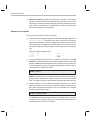
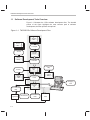
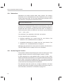
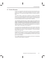
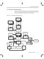
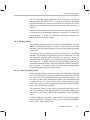
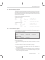
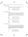
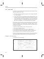
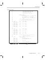
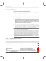
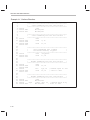
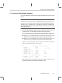
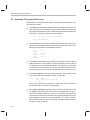
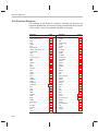
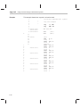
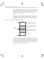
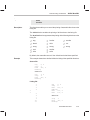
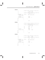
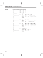
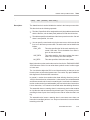
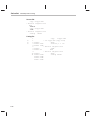
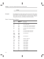
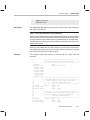
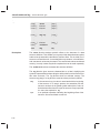
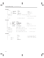
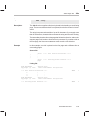
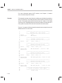
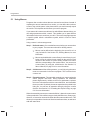
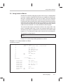
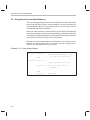
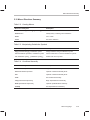
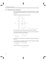
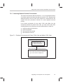
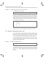
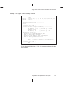
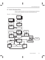
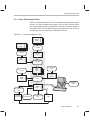
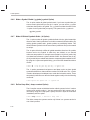
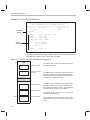
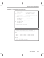
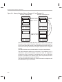
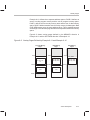
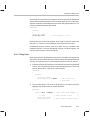
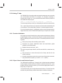
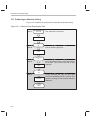
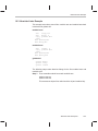
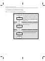
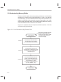
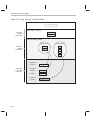
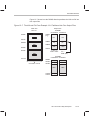
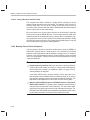
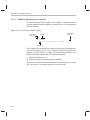
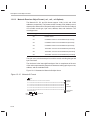
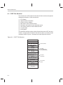
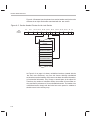
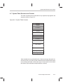
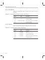
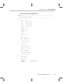
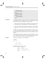
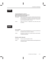
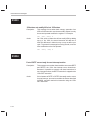
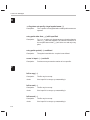
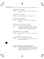
1.1 Software Development Tools Overview
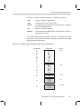
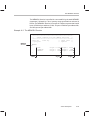
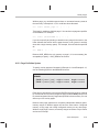
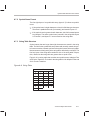
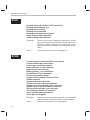
Figure 1–1 illustrates the ’C55x software development flow. The shaded
portion of the figure highlights the most common path of software
development; the other portions are optional.
Figure 1–1. TMS320C55x Software Development Flow
C
source
files
Macro
source
files
C compiler
Archiver
Assembler
source
Macro
library
Assembler
Archiver
Library of
object
files
1-2
Library-build
utility
Runtimesupport
library
Linker
Debugging
tools
Executable
COFF
file
Hex conversion
utility
EPROM
programmer
COFF
object
files
Absolute lister
Cross-reference
lister
’C55x
Tools Descriptions
1.2 Tools Descriptions
The following list describes the tools that are shown in Figure 1–1:
- The C compiler translates C source code into ’C55x assembly language
source code. The compiler package includes the library-build utility, with
which you can build your own runtime libraries. The C compiler is not
shipped with the assembly language tools package.
- The assembler translates assembly language source files into machine
language COFF object files. The TMS320C55x tools include two
assemblers. The mnemonic assembler accepts ’C54x and ’C55x
mnemonic assembly source files. The algebraic assembler accepts ’C55x
algebraic assembly source files. Source files can contain instructions,
assembler directives, and macro directives. You can use assembler directives to control various aspects of the assembly process, such as the
source listing format, data alignment, and section content.
- The linker combines relocatable COFF object files (created by the
assembler) into a single executable COFF object module. As it creates the
executable module, it binds symbols to memory locations and resolves all
references to those symbols. It also accepts archiver library members and
output modules created by a previous linker run. Linker directives allow
you to combine object file sections, bind sections or symbols to addresses
or within memory ranges, and define or redefine global symbols.
- The archiver collects a group of files into a single archive file. For
example, you can collect several macros into a macro library. The
assembler searches the library and uses the members that are called as
macros by the source file. You can also use the archiver to collect a group
of object files into an object library. The linker includes in the library the
members that resolve external references during the link.
- The library-build utility builds your own customized, C, runtime-support
library. Standard runtime-support library functions are provided as source
code in rts.src and as object code in rts55.lib.
- The TMS320C55x DSP accepts COFF files as input, but most EPROM
programmers do not. The hex conversion utility converts a COFF object
file into TI-tagged, Intel, Motorola, or Tektronix object format. The
converted file can be downloaded to an EPROM programmer.
Introduction
1-3
Tools Descriptions
- The absolute lister accepts linked object files as input and creates .abs
files as output. You assemble .abs files to produce a listing that contains
absolute rather than relative addresses. Without the absolute lister,
producing such a listing would be tedious and require many manual operations.
- The cross-reference lister uses object files to produce a cross-reference
listing showing symbols, their definitions, and their references in the linked
source files.
The purpose of this development process is to produce a module that can be
executed in a ’C55x target system. You can use one of several debugging tools
to refine and correct your code. Available products include:
- An instruction-accurate software simulator
- An XDS emulator
1-4
Chapter 2
Introduction to Common Object File Format
The assembler and linker create object files that can be executed by a
TMS320C55x device. The format for these object files is called common
object file format (COFF).
COFF makes modular programming easier, because it encourages you to
think in terms of blocks of code and data when you write an assembly language
program. These blocks are known as sections. Both the assembler and the
linker provide directives that allow you to create and manipulate sections.
This chapter provides an overview of COFF sections. For additional
information, see Appendix A, Common Object File Format, which explains the
COFF structure.
Topic
Page
2.1
Sections . . . . . . . . . . . . . . . . . . . . . . . . . . . . . . . . . . . . . . . . . . . . . . . . . . . . . . 2-2
2.2
How the Assembler Handles Sections . . . . . . . . . . . . . . . . . . . . . . . . . . . 2-4
2.3
How the Linker Handles Sections . . . . . . . . . . . . . . . . . . . . . . . . . . . . . . 2-12
2.4
Relocation . . . . . . . . . . . . . . . . . . . . . . . . . . . . . . . . . . . . . . . . . . . . . . . . . . . 2-15
2.5
Runtime Relocation . . . . . . . . . . . . . . . . . . . . . . . . . . . . . . . . . . . . . . . . . . 2-17
2.6
Loading a Program . . . . . . . . . . . . . . . . . . . . . . . . . . . . . . . . . . . . . . . . . . . 2-18
2.7
Symbols in a COFF File . . . . . . . . . . . . . . . . . . . . . . . . . . . . . . . . . . . . . . . 2-19
Introduction to Common Object File Format
2-1
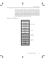
Sections
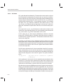
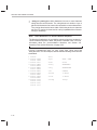
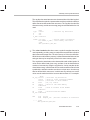
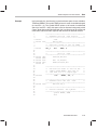
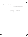
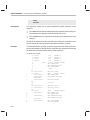
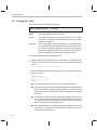
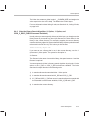
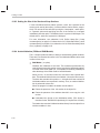
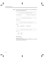
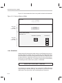
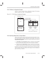
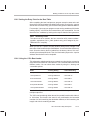
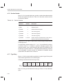
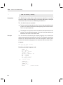
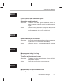
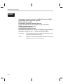
2.1
Sections
The smallest unit of an object file is called a section. A section is a block of code
or data that will ultimately occupy contiguous space in the memory map. Each
section of an object file is separate and distinct. COFF object files always contain three default sections:
.text section
contains executable code
.data section
usually contains initialized data
.bss section
usually reserves space for uninitialized variables
In addition, the assembler and linker allow you to create, name, and link
named sections that are used like the .data, .text, and .bss sections.
There are two basic types of sections:
initialized sections
contain data or code. The .text and .data sections
are initialized; named sections created with the
.sect assembler directive are also initialized.
uninitialized sections
reserve space for uninitialized data. The .bss section is uninitialized; named sections created with
the .usect assembler directive are also uninitialized.
Several assembler directives allow you to associate various portions of code
and data with the appropriate sections. The assembler builds these sections
during the assembly process, creating an object file organized as shown in
Figure 2–1.
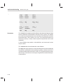
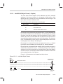
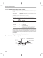
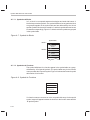
One of the linker’s functions is to relocate sections into the target memory
map; this function is called allocation. Because most systems contain several
types of memory, using sections can help you use target memory more efficiently. All sections are independently relocatable; you can place any section
into any allocated block of target memory. For example, you can define a section that contains an initialization routine and then allocate the routine into a
portion of the memory map that contains ROM.
2-2
Sections
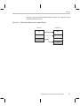
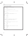
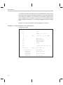
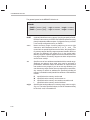
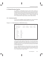
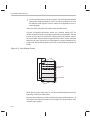
Figure 2–1 shows the relationship between sections in an object file and a
hypothetical target memory.
Figure 2–1. Partitioning Memory Into Logical Blocks
Object File
Target Memory
.bss
RAM
.data
EEPROM
.text
ROM
Introduction to Common Object File Format
2-3
How the Assembler Handles Sections
2.2
How the Assembler Handles Sections
The assembler identifies the portions of an assembly language program that
belong in a section. The assembler has several directives that support this
function:
-
.bss
.usect
.text
.data
.sect
The .bss and .usect directives create uninitialized sections; the other
directives create initialized sections.
You can create subsections of any section to give you tighter control of the
memory map. Subsections are created using the .sect and .usect directives.
Subsections are identified with the base section name and a subsection name
separated by a colon. See subsection 2.2.4, Subsections, page 2-8, for more
information.
Note:
Default Section Directive
If you don’t use any of the sections directives, the assembler assembles
everything into the .text section.
2.2.1
Uninitialized Sections
Uninitialized sections reserve space in processor memory; they are usually
allocated into RAM. These sections have no actual contents in the object file;
they simply reserve memory. A program can use this space at runtime for
creating and storing variables.
Uninitialized data areas are built by using the .bss and .usect assembler
directives.
- The .bss directive reserves space in the .bss section.
- The .usect directive reserves space in a specific, uninitialized named
section.
Each time you invoke the .bss directive, the assembler reserves more space
in the appropriate section. Each time you invoke the .usect directive, the
assembler reserves more space in the specified named section.
2-4
How the Assembler Handles Sections
The syntax for these directives is:
.bss symbol, size in words [, [blocking flag] [, alignment flag]]
symbol .usect ”section name ”, size in words [, [blocking flag] [, alignment flag]]
symbol
points to the first word reserved by this invocation of the
.bss or .usect directive. The symbol corresponds to the
name of the variable that you’re reserving space for. It can
be referenced by any other section and can also be declared as a global symbol (with the .global assembler directive).
size in words
is an absolute expression.
- The .bss directive reserves size words in the .bss sec-
tion.
- The .usect directive reserves size words in section
name.
blocking flag
is an optional parameter. If you specify a value other than
0 for this parameter, the assembler associates size words
contiguously; the allocated space will not cross a page
boundary, unless size is greater than a page, in which case
the object will start on a page boundary.
alignment flag
is an optional parameter. If you specify a value other than
0 for this parameter, the section is aligned to a long word
boundary.
section name
tells the assembler which named section to reserve space
in. For more information about named sections, see
subsection 2.2.3, Named Sections, on page 2-7.
The .text, .data, and .sect directives tell the assembler to stop assembling into
the current section and begin assembling into the indicated section. The .bss
and .usect directives, however, do not end the current section and begin a new
one; they simply escape temporarily from the current section. The .bss and
.usect directives can appear anywhere in an initialized section without
affecting its contents.
Uninitialized subsections can be created with the .usect directive. The assembler treats uninitialized subsections in the same manner as uninitialized
sections. See subsection 2.2.4, Subsections, on page 2-8 for more information on creating subsections.
Introduction to Common Object File Format
2-5
How the Assembler Handles Sections
2.2.2
Initialized Sections
Initialized sections contain executable code or initialized data. The contents
of these sections are stored in the object file and placed in processor memory
when the program is loaded. Each initialized section is independently relocatable and may reference symbols that are defined in other sections. The linker
automatically resolves these section-relative references.
Three directives tell the assembler to place code or data into a section. The
syntaxes for these directives are:
.text [value]
.data [value]
.sect ”section name” [, value]
When the assembler encounters one of these directives, it stops assembling
into the current section (acting as an implied end-current-section command).
It then assembles subsequent code into the designated section until it encounters another .text, .data, or .sect directive. The value, if present, specifies the
starting value of the section program counter. The starting value of the section
program counter can be specified only once; it must be done the first time the
directive for that section is encountered. By default, the SPC starts at 0.
Sections are built through an iterative process. For example, when the assembler first encounters a .data directive, the .data section is empty. The statements following this first .data directive are assembled into the .data section
(until the assembler encounters a .text or .sect directive). If the assembler
encounters subsequent .data directives, it adds the statements following
these .data directives to the statements already in the .data section. This
creates a single .data section that can be allocated contiguously into memory.
Initialized subsections can be created with the .sect directive. The assembler
treats initialized subsections in the same manner as initialized sections. See
subsection 2.2.4, Subsections, on page 2-8 for more information on creating
subsections.
2-6
How the Assembler Handles Sections
2.2.3
Named Sections
Named sections are sections that you create. You can use them like the default .text, .data, and .bss sections, but they are assembled separately.
For example, repeated use of the .text directive builds up a single .text section
in the object file. When linked, this .text section is allocated into memory as
a single unit. Suppose there is a portion of executable code (perhaps an initialization routine) that you don’t want allocated with .text. If you assemble this
segment of code into a named section, it is assembled separately from .text,
and you can allocate it into memory separately. You can also assemble initialized data that is separate from the .data section, and you can reserve space
for uninitialized variables that is separate from the .bss section.
The following directives let you create named sections:
- The .usect directive creates sections that are used like the .bss section.
These sections reserve space in RAM for variables.
- The .sect directive creates sections, like the default .text and .data
sections, that can contain code or data. The .sect directive creates named
sections with relocatable addresses.
The syntax for these directives is shown below:
symbol .usect ”section name”, size in words [, [blocking flag] [, alignment flag]]
.sect ”section name”
The section name parameter is the name of the section. You can create up to
32 767 separate named sections. A section name can be up to 200 characters. For the .sect and .usect directives, a section name can refer to a subsection (see subsection 2.2.4, Subsections, for details).
Each time you invoke one of these directives with a new name, you create a
new named section. Each time you invoke one of these directives with a name
that was already used, the assembler assembles code or data (or reserves
space) into the section with that name. You cannot use the same names with
different directives. That is, you cannot create a section with the .usect directive and then try to use the same section with .sect.
Introduction to Common Object File Format
2-7
How the Assembler Handles Sections
2.2.4
Subsections
Subsections are smaller sections within larger sections. Like sections,
subsections can be manipulated by the linker. Subsections give you tighter
control of the memory map. You can create subsections by using the .sect or
.usect directive. The syntax for a subsection name is:
section name:subsection name
A subsection is identified by the base section name followed by a colon, then
the name of the subsection. A subsection can be allocated separately or
grouped with other sections using the same base name. For example, to
create a subsection called _func within the .text section, enter the following:
.sect ”.text:_func”
You can allocate _func separately or with other .text sections.
You can create two types of subsections:
- Initialized subsections are created using the .sect directive. See
subsection 2.2.2, Initialized Sections, on page 2-6.
- Uninitialized subsections are created using the .usect directive. See
subsection 2.2.1, Uninitialized Sections, on page 2-4.
Subsections are allocated in the same manner as sections. See Section 9.9,
The SECTIONS Directive, on page 9-32 for more information.
2.2.5
Section Program Counters
The assembler maintains a separate program counter for each section. These
program counters are known as section program counters, or SPCs.
An SPC represents the current address within a section of code or data.
Initially, the assembler sets each SPC to 0. As the assembler fills a section with
code or data, it increments the appropriate SPC. If you resume assembling
into a section, the assembler remembers the appropriate SPC’s previous value and continues incrementing the SPC at that point.
The assembler treats each section as if it began at address 0; the linker
relocates each section according to its final location in the memory map. For
more information, see Section 2.4, Relocation, on page 2-15.
2-8
How the Assembler Handles Sections
2.2.6
An Example That Uses Sections Directives
Example 2–1 shows how you can build COFF sections incrementally, using
the sections directives to swap back and forth between the different sections.
You can use sections directives to begin assembling into a section for the first
time, or to continue assembling into a section that already contains code. In
the latter case, the assembler simply appends the new code to the code that
is already in the section.
The format in Example 2–1 is a listing file. Example 2–1 shows how the SPCs
are modified during assembly. A line in a listing file has four fields:
Field 1
contains the source code line counter.
Field 2
contains the section program counter.
Field 3
contains the object code.
Field 4
contains the original source statement.
Introduction to Common Object File Format
2-9
How the Assembler Handles Sections
Example 2–1. Using Sections Directives
2
3
4
5
6
7
8
9
10
11
12
13
14
15
16
17
18
19
20
21
000000
000000 0011
000001 0022
000002 0033
000000
000003 0123
000000
000000
000002
000004
000006
A01E
4210
0450
FB
22
23
24
25 000004
26 000004 00AA
000005 00BB
000006 00CC
27
28
29
30 000000
31 000001
32
33
34
35 000007
36 000007 A114
37 000009 5272
38 00000b 1E0A
00000d 90
39 00000e 0471
000010 F8
40
41
42
43 000000
44 000000 0011
45 000001 0033
Field 1 Field 2
2-10
Field 3
************************************************
** Assemble an initialized table into .data. **
************************************************
.data
coeff
.word
011h,022h,033h
************************************************
**
Reserve space in .bss for a variable.
**
************************************************
.bss
buffer,10
************************************************
**
Still in .data.
**
************************************************
ptr
.word
0123h
************************************************
**
Assemble code into the .text section.
**
************************************************
.text
add:
MOV
0Fh,AC0
aloop:
SUB
#1,AC0
BCC
aloop,AC0>=#0
************************************************
**
Another initialized table into .data.
**
************************************************
.data
ivals
.word
0AAh, 0BBh, 0CCh
************************************************
** Define another section for more variables. **
************************************************
var2
.usect
”newvars”, 1
inbuf
.usect
”newvars”, 7
************************************************
**
Assemble more code into .text.
**
************************************************
.text
mpy:
MOV
0Ah,AC1
mloop:
MOV
T3,HI(AC2)
MPYK
#10,AC2,AC1
BCC
mloop,!overflow(AC1)
************************************************
** Define a named section for int. vectors. **
************************************************
.sect
”vectors”
.word
011h, 033h
Field 4
How the Assembler Handles Sections
As Figure 2–2 shows, the file in Example 2–1 creates five sections:
.text
contains 17 bytes of object code.
.data
contains seven words of object code.
vectors
is a named section created with the .sect directive; it contains
two words of initialized data.
.bss
reserves 10 words in memory.
newvars
is a named section created with the .usect directive; it reserves
eight words in memory.
The second column shows the object code that is assembled into these
sections; the first column shows the line numbers of the source statements
that generated the object code.
Figure 2–2. Object Code Generated by the File in Example 2–1
Line Numbers
19
20
21
21
36
37
38
38
39
39
6
6
6
14
26
26
26
Object Code
A01E
4210
0450
FB
A114
5272
1E0A
90
0471
F8
Section
.text
0011
0022
0033
0123
00aa
00bb
00cc
.data
44
45
0011
0033
vectors
No data—
10 words
reserved
.bss
10
30
31
No data—
eight words
reserved
newvars
Introduction to Common Object File Format
2-11
How the Linker Handles Sections
2.3
How the Linker Handles Sections
The linker has two main functions related to sections. First, the linker uses the
sections in COFF object files as building blocks; it combines input sections
(when more than one file is being linked) to create output sections in an executable COFF output module. Second, the linker chooses memory addresses for
the output sections.
Two linker directives support these functions:
- The MEMORY directive allows you to define the memory map of a target
system. You can name portions of memory and specify their starting
addresses and their lengths.
- The SECTIONS directive tells the linker how to combine input sections
into output sections and where to place these output sections in memory.
Subsections allow you to manipulate sections with greater precision. You can
specify subsections with the linker’s SECTIONS directive. If you do not specify
a subsection explicitly, then the subsection is combined with the other sections
with the same base section name.
It is not always necessary to use linker directives. If you don’t use them, the
linker uses the target processor’s default allocation algorithm described in
Section 9.13, Default Allocation Algorithm, on page 9-55. When you do use
linker directives, you must specify them in a linker command file.
Refer to the following sections for more information about linker command files
and linker directives:
Section Number
2-12
Section Name
Page
9.6
Linker Command Files
9-22
9.8
The MEMORY Directive
9-28
9.9
The SECTIONS Directive
9-32
9.13
Default Allocation Algorithm
9-55
How the Linker Handles Sections
2.3.1
Default Memory Allocation
Figure 2–3 illustrates the process of linking two files.
Figure 2–3. Combining Input Sections to Form an Executable Object Module
ÏÏÏÏÏ
ÏÏÏÏÏ
Program Memory
file1.obj
.text
file 1
.text
.data
file 2
.text
.bss
file 1
.data
table_1
(initialized
named section)
file 2
.data
u_vars
(uninitialized
named section)
file 1
table_1
ÏÏÏÏÏ
ÏÏÏÏÏ
ÏÏÏÏÏ
Data Memory
unconfigured
file1
.bss
file2
.bss
file1
U_vars
file2
U_vars
file2.obj
file 2
table_1
.text
file2
FFT
.data
.bss
table_1
(initialized
named section)
unused
ÏÏÏÏÏ
ÏÏÏÏÏ
ÏÏÏÏÏ
unconfigured
unused
u_vars
(uninitialized
named section)
FFT
(initialized
named section)
In Figure 2–3, file1.obj and file2.obj have been assembled to be used as linker
input. Each contains the .text, .data, and .bss default sections; in addition,
each contains named sections. The executable output module shows the
combined sections. The linker combines file1.text with file2.text to form one
.text section, then combines the .data sections, then the .bss sections, and
finally places the named sections at the end. The memory map shows how the
sections are put into memory; by default, the linker begins at address 080h and
places the sections one after the other as shown.
Introduction to Common Object File Format
2-13
How the Linker Handles Sections
2.3.2
Placing Sections in the Memory Map
Figure 2–3 illustrates the linker’s default methods for combining sections.
Sometimes you may not want to use the default setup. For example, you may
not want all of the .text sections to be combined into a single .text section. Or
you may want a named section placed where the .data section would normally
be allocated. Most memory maps contain various types of memory (RAM,
ROM, EPROM, etc.) in varying amounts; you may want to place a section in
a specific type of memory.
For further explanation of section placement within the memory map, see
Section 9.8, The MEMORY Directive, on page 9-28 and Section 9.9, The
SECTIONS Directive, on page 9-32.
2-14
Relocation
2.4 Relocation
The assembler treats each section as if it began at address 0. All relocatable
symbols (labels) are relative to address 0 in their sections. Of course, all
sections can’t actually begin at address 0 in memory, so the linker relocates
sections by:
- Allocating them into the memory map so that they begin at the appropriate
address
- Adjusting symbol values to correspond to the new section addresses
- Adjusting references to relocated symbols to reflect the adjusted symbol
values
The linker uses relocation entries to adjust references to symbol values. The
assembler creates a relocation entry each time a relocatable symbol is referenced. The linker then uses these entries to patch the references after the
symbols are relocated. Example 2–2 contains a code segment for the ’C55x
that generates relocation entries.
Example 2–2. Code That Generates Relocation Entries
(a) Mnemonic example
1
2 000000
3 000000 4A04
4 000002 7600
000004 0008!
5 000006 9400
.ref
X
.text
B
Y
MOV
#X,AC0 ;Generates relocation entry
Y: reset
(b) Algebraic example
1
2 000000
3 000000 4A04
4 000002 7600
000004 0008!
5 000006 9400
.ref
X
.text
goto #Y
AC0 = #X
;Generates relocation entry
Y: reset
Introduction to Common Object File Format
2-15
Relocation
In Example 2–2, symbol X is relocatable since it is defined in another module.
Symbol Y is relative to the PC and relocation is not necessary. When the code
is assembled, X has a value of 0 (the assembler assumes all undefined external symbols have values of 0). The assembler generates a relocation entry for
X. The reference to X is an external reference (indicated by the ! character in
the listing).
Each section in a COFF object file has a table of relocation entries. The table
contains one relocation entry for each relocatable reference in the section.
The linker usually removes relocation entries after it uses them. This prevents
the output file from being relocated again (if it is relinked or when it is loaded).
A file that contains no relocation entries is an absolute file (all its addresses
are absolute addresses). If you want the linker to retain relocation entries, invoke the linker with the –r option.
2-16
Runtime Relocation
2.5
Runtime Relocation
At times, you may want to load code into one area of memory and run it in
another. For example, you may have performance-critical code in a ROMbased system. The code must be loaded into ROM, but it would run faster in
RAM.
The linker provides a simple way to handle this. Using the SECTIONS
directive, you can optionally direct the linker to allocate a section twice: first
to set its load address, and again to set its run address. Use the load keyword
for the load address and the run keyword for the run address.
The load address determines where a loader will place the raw data for the
section. Any references to the section (such as labels in it) refer to its run
address. The application must copy the section from its load address to its run
address; this does not happen automatically simply because you specify a
separate run address. For an example that illustrates how to move a block of
code at runtime, see Example 9–6 on page 9-43.
If you provide only one allocation (either load or run) for a section, the section
is allocated only once and will load and run at the same address. If you provide
both allocations, the section is actually allocated as if it were two different
sections of the same size.
Uninitialized sections (such as .bss) are not loaded, so the only significant
address is the run address. The linker allocates uninitialized sections only
once: if you specify both run and load addresses, the linker warns you and
ignores the load address.
For a complete description of runtime relocation, see Section 9.10, Specifying
a Section’s Runtime Address, on page 9-41.
Introduction to Common Object File Format
2-17
Loading a Program
2.6 Loading a Program
The linker produces executable COFF object modules. An executable object
file has the same COFF format as object files that are used as linker input; the
sections in an executable object file, however, are combined and relocated so
that they can be loaded directly into target memory.
Several methods can be used for loading a program, depending on the execution environment. Two common situations are described below.
- The TMS320C55x debugging tools, including the software simulator and
software development system, have built-in loaders. Each of these tools
contains a LOAD command that invokes a loader; the loader reads the
executable file and copies the program into target memory.
- You can use the hex conversion utility (hex55, which is shipped as part of
the assembly language package) to convert the executable COFF object
module into one of several object file formats. You can then use the converted file with an EPROM programmer to burn the program into an
EPROM.
2-18
Symbols in a COFF File
2.7
Symbols in a COFF File
A COFF file contains a symbol table that stores information about symbols in
the program. The linker uses this table when it performs relocation. Debugging
tools can also use the symbol table to provide symbolic debugging.
2.7.1
External Symbols
External symbols are symbols that are defined in one module and referenced
in another module. You can use the .def, .ref, or .global directives to identify
symbols as external:
.def
Defined in the current module and used in another module
.ref
Referenced in the current module, but defined in another
module
.global
May be either of the above
The following code segment illustrates these definitions.
x:
.def
.ref
ADD
B
x
y
#86,AC0,AC0
y
;
;
;
;
DEF of x
REF of y
Define x
Reference y
The .def definition of x says that it is an external symbol defined in this module
and that other modules can reference x. The .ref definition of y says that it is
an undefined symbol that is defined in another module.
The assembler places both x and y in the object file’s symbol table. When the
file is linked with other object files, the entry for x defines unresolved
references to x from other files. The entry for y causes the linker to look
through the symbol tables of other files for y’s definition.
The linker must match all references with corresponding definitions. If the
linker cannot find a symbol’s definition, it prints an error message about the
unresolved reference. This type of error prevents the linker from creating an
executable object module.
Introduction to Common Object File Format
2-19
Symbols in a COFF File
2.7.2
The Symbol Table
The assembler always generates an entry in the symbol table when it encounters an external symbol (both definitions and references). The assembler also
creates special symbols that point to the beginning of each section; the linker
uses these symbols to resolve the address of and references symbols that are
defined in the section.
The assembler does not usually create symbol table entries for any symbols
other than those described above, because the linker does not use them. For
example, labels are not included in the symbol table unless they are declared
with .global. For symbolic debugging purposes, it is sometimes useful to have
entries in the symbol table for each symbol in a program. To accomplish this,
invoke the assembler with the –s option.
2-20
Chapter 3
Assembler Description
The assembler translates assembly language source files into machine
language object files. These files are in common object file format (COFF),
which is discussed in Chapter 2, Introduction to Common Object File Format,
and Appendix A, Common Object File Format. Source files can contain the
following assembly language elements:
Assembler directives
described in Chapter 4
Macro directives
described in Chapter 5
Assembly language instructions
described in the TMS320C55x
Instruction Set Reference Guides
Topic
Page
3.1
Assembler Overview . . . . . . . . . . . . . . . . . . . . . . . . . . . . . . . . . . . . . . . . . . 3-2
3.2
Assembler Development Flow . . . . . . . . . . . . . . . . . . . . . . . . . . . . . . . . . . 3-3
3.3
Invoking the Assembler . . . . . . . . . . . . . . . . . . . . . . . . . . . . . . . . . . . . . . . . 3-4
3.4
’C55x Assembler Features . . . . . . . . . . . . . . . . . . . . . . . . . . . . . . . . . . . . . 3-7
3.5
Naming Alternate Files and Directories for Assembler Input . . . . . . 3-14
3.6
Source Statement Format . . . . . . . . . . . . . . . . . . . . . . . . . . . . . . . . . . . . . 3-17
3.7
Constants . . . . . . . . . . . . . . . . . . . . . . . . . . . . . . . . . . . . . . . . . . . . . . . . . . . 3-21
3.8
Character Strings . . . . . . . . . . . . . . . . . . . . . . . . . . . . . . . . . . . . . . . . . . . . 3-24
3.9
Symbols . . . . . . . . . . . . . . . . . . . . . . . . . . . . . . . . . . . . . . . . . . . . . . . . . . . . . 3-25
3.10 Expressions . . . . . . . . . . . . . . . . . . . . . . . . . . . . . . . . . . . . . . . . . . . . . . . . . 3-31
3.11 Built-In Functions . . . . . . . . . . . . . . . . . . . . . . . . . . . . . . . . . . . . . . . . . . . . 3-34
3.12 Source Listings . . . . . . . . . . . . . . . . . . . . . . . . . . . . . . . . . . . . . . . . . . . . . . 3-36
3.13 Cross-Reference Listing . . . . . . . . . . . . . . . . . . . . . . . . . . . . . . . . . . . . . . 3-40
Assembler Description
3-1
Assembler Overview
3.1 Assembler Overview
TMS320C55x has two assemblers:
- masm55 (the mnemonic assembler) accepts ’C54x mnemonic and ’C55x
mnemonic assembly source.
- asm55 (the algebraic assembler) accepts only ’C55x algebraic assembly
source.
Each assembler does the following:
- Processes the source statements in a text file to produce a relocatable
’C55x object file
- Produces a source listing (if requested) and provides you with control over
this listing
- Allows you to segment your code into sections and maintain an SPC
(section program counter) for each section of object code
- Defines and references global symbols and appends a cross-reference
listing to the source listing (if requested)
- Assembles conditional blocks
- Supports macros, allowing you to define macros inline or in a library
The masm55 assembler generates error and warning messages for ’C54x
instructions that are not supported. Some ’C54x instructions do not map
directly to a single ’C55x instruction. The masm55 assembler will translate
these instructions into an appropriate series of ’C55x instructions. The listing
file generated by the assembler (with the –l option) shows the translations that
have occurred.
3-2
Assembler Development Flow
3.2 Assembler Development Flow
Figure 3–1 illustrates the assembler’s role in the assembly language development flow. The assembler accepts assembly language source files as input,
whether created by the assembler itself or by the C compiler.
Figure 3–1. Assembler Development Flow
C
source
files
Macro
source
files
C compiler
Archiver
Assembler
source
Macro
library
Assembler
Archiver
Library of
object
files
Library-build
utility
Runtimesupport
library
Linker
Debugging
tools
Executable
COFF
file
Hex conversion
utility
EPROM
programmer
COFF
object
files
Absolute lister
Cross-reference
lister
’C55x
Assembler Description
3-3
Invoking the Assembler
3.3 Invoking the Assembler
To invoke the assembler, enter the following:
masm55 [input file [object file [listing file ] ] ] [–options ]
asm55 [input file [object file [listing file ] ] ] [–options ]
masm55
asm55
are the commands that invoke the assembler. masm55 invokes
the mnemonic assembler. asm55 invokes the algebraic
assembler.
input file
names the assembly language source file. If you do not supply
an extension, the assembler uses the default extension .asm,
unless the –f assembler option is used. If you do not supply an
input filename, the assembler prompts you for one.
object file
names the ’C55x object file that the assembler creates. If you do
not supply an extension, the assembler uses .obj as a default.
If you do not supply an object file, the assembler creates a file
that uses the input filename with the .obj extension.
listing file
names the optional listing file that the assembler can create.
- If you do not supply a listing file, the assembler does not
create one unless you use the –l (lowercase L) option or the
–x option. In this case, the assembler uses the input filename with a .lst extension and places the listing file in the input file directory.
- If you supply a listing file but do not supply an extension, the
assembler uses .lst as the default extension.
options
3-4
identifies the assembler options that you want to use. Options
are not case-sensitive and can appear anywhere on the command line, following the assembler name. Precede each option
with a hyphen. Single-letter options without parameters can be
combined: for example, –lc is equivalent to –l –c. Options that
have parameters, such as –i, must be specified separately.
–@
–@filename appends the contents of filename to the
command line. You can use this option to avoid the
limitations on command line length imposed by the host
operating system.
–a
creates an absolute listing. When you use –a, the
assembler does not produce an object file. The –a option
is used in conjunction with the absolute lister.
Invoking the Assembler
–c
makes case insignificant in the assembly language files.
For example, –c will make the symbols ABC and abc
equivalent. If you do not use this option, case is significant (default). Case significance is enforced primarily
with symbol names, not with mnemonics and register
names.
–d
–dname [=value] sets the name symbol. This is equivalent to inserting name .set value at the beginning of the
assembly file. If value is omitted, the symbol is set to 1.
For more information, see subsection 3.9.3, Defining
Symbolic Constants (–d Option), on page 3-26.
–f
suppresses the assembler’s default behavior of adding
a .asm extension to a source file name that does not already include an extension.
–g
enables assembler source debugging in the C source
debugger. Line information is output to the COFF file for
every line of source in the assembly language source
file. Note that you cannot use the –g option on assembly
code that already contains .line directives (i.e., code that
was generated by the C compiler run with –g).
–h
any of these options displays a listing of the available
–help assembler options.
–?
–hc
–hcfilename tells the assembler to copy the specified
file for the assembly module. The file is inserted
before source file statements. The copied file appears
in the assembly listing files.
–hi
–hifilename tells the assembler to include the specified file for the assembly module. The file is included
before source file statements. The included file does
not appear in the assembly listing files.
–i
specifies a directory where the assembler can find files
named by the .copy, .include, or .mlib directives. The format of the –i option is –ipathname. For more information,
see subsection 3.5.1, –i Assembler Option, on page
3-14.
–l
(lowercase L) produces a listing file.
–ma
(ARMS mode) informs the assembler that the ARMS
status bit will be enabled during the execution of this
source file. By default, the assembler assumes that
the bit is disabled.
Assembler Description
3-5
Invoking the Assembler
3-6
–mb
controls the severity of diagnostic messages printed
for bus conflicts between parallel instructions. By default, bus conflicts are reported as errors. When the
–mb option is used, bus conflicts will be reported as
warnings.
–mc
(CPL mode) informs the assembler that the CPL status bit will be enabled during the execution of this
source file. This causes the assembler to enforce the
use of SP-relative addressing syntax. By default, the
assembler assumes that the bit is disabled.
–ml
(’C54x compatibility mode) informs the assembler that
the C54CM status bit will be enabled during the execution of this source file. By default, the assembler
assumes that the bit is disabled.
–mv
causes the assembler to use the largest (P24) form of
certain variable-length instructions. By default, the
assembler tries to resolve all variable-length instructions to their smallest size.
–mw
suppresses assembler warning messages. (Supported for asm55 only.)
–q
(quiet) suppresses the banner and all progress
information.
–r
–rnum suppresses the assembler remark identified by
num. A remark is an informational assembler message
that is less severe than a warning. If you do not specify
a value for num, all remarks will be suppressed.
–s
puts all defined symbols in the object file’s symbol table.
The assembler usually puts only global symbols into the
symbol table. When you use –s, symbols defined as
labels or as assembly-time constants are also placed in
the table.
–u
–uname undefines the predefined constant name,
which overrides any –d options for the specified
constant.
–x
produces a cross-reference table and appends it to the
end of the listing file; also adds cross-reference information to the object file for use by the cross-reference utility.
If you do not request a listing file, the assembler creates
one anyway.
’C55x Assembler Features
3.4 ’C55x Assembler Features
The sections that follow provide important information on features specific to
the ’C55x assembler:
- byte/word addressing (Section 3.4.1)
- parallel instruction rules (Section 3.4.2)
- variable-length instructions (Section 3.4.3)
- memory modes (Section 3.4.4)
3.4.1
Byte/Word Addressing
’C55x memory is byte-addressable for code and word-addressable for data.
The assembler and linker keep track of the addresses, relative offsets, and
sizes of the bits in units that are appropriate for the given section: words for
data sections, and bytes for code sections.
Note:
Offsets in .struct and .union constructs
Offsets of fields defined in .struct or .union constructs are always counted
in words, regardless of the current section. The assembler assumes that a
.struct or .union is always used in a data context.
3.4.1.1
Definition of Code Sections
The assembler identifies a section as a code section if:
- the section is introduced with a .text directive, or
- the section has at least one instruction assembled into it.
If a section is not established with a .text, .data., or .sect directive, the
assembler assumes that it is a .text (code) section. Because the section type
determines the assembler’s offset and size computations, it is important to
clearly define your current working section as code or data before assembling
bits into the section.
Assembler Description
3-7
’C55x Assembler Features
3.4.1.2
Assembly Programs and Native Units
The assembler and the linker assume that your code is written using word
addresses and offsets in the context of data segments, and byte addresses
and offsets in the context of code segments:
- If an address is to be sent via a program address bus (e.g., an address
used as the target of a call or a branch), the processor expects a full 24-bit
address. A constant used in this context should be expressed in bytes. A
label defined in a code section can be handled correctly by the assembler
and linker. However, a label defined in a data section cannot be used in
this context.
- If an address is to be sent via a data address bus (e.g., an address denotes
a location in memory to be read or written), the processor expects a 23-bit
word address. A constant used in this context should be expressed in
words. A label defined in a data section can be handled correctly by the
assembler and linker. However, a label defined in a code section cannot
be used in this context.
- The PC-value column of the assembly listing file is counted in units that
are appropriate for the section being listed. For code sections, the PC is
counted in bytes; for data sections, it is counted in words.
For example:
1
2
3
4
5
6
000000
000000 2298
000002 4010
000000
000000
000001
000002
000003
7 000004
0004
0005
0006
0007
0001
.text
; PC is counted in BYTES
MOV AR1,AR0
ADD #1,AC0
.data
; PC is counted in WORDS
.word 4,5,6,7
; PC is 1 word
; PC is 2 words ...
foo
.word 1
- The data placement directives that operate on characters (.byte, .ubyte,
.char, .uchar, and .string) allocate one character per byte when in a code
section, and one character to a word when in a data section. However,
Texas Instruments highly recommends that you use these directives only
in data sections.
3-8
’C55x Assembler Features
- Directives that have a size parameter expressed in addressable units ex-
pect this parameter to be expressed in bytes for a code section, and in
words for a data section.
For example,
.align 2
aligns the PC to a 2-byte (16-bit) boundary in a code section, and to a
2-word (32-bit) boundary in a data section.
The code examples below display data and code for ’C55x.
Example 3–1. ’C55x Data Example
.def Struct1, Struct2
.bss Struct1, 8 ; allocate 8 WORDS for Struct1
.bss Struct2, 6 ; allocate 6 WORDS for Struct2
.text
MOV *(#(Struct1 + 2)),T0 ; load 3rd WORD of Struct1
MOV *(#1000h),T1
; 0x1000 is an absolute WORD
; address (i.e., byte 0x2000)
Example 3–2. ’C55x Code Example
.text
.ref Func
CALL #(Func + 3) ;jump to address “Func plus 3 BYTES”
CALL #0x1000
;0x1000 is an absolute BYTE address
3.4.1.3
Using Code as Data and Data as Code
The assembler does not support using a code address as if it were a data
address (e.g., attempting to read or write data to program space). Similarly,
the assembler does not support using a data address as if it were a code address (e.g., executing a branch to a data label). This functionality cannot be
supported because of the difference in the size of the addressable units: a
code label address is a 24-bit byte address while a data label address is a
23-bit word address.
Consequently:
- You should not mix code and data within one section. All data (even
constant data) should be placed into a section separate from code.
- Applications that attempt to read and write bits into program sections will
not work.
Assembler Description
3-9
’C55x Assembler Features
3.4.2
Parallel Instruction Rules
The assembler performs semantic checking of parallel pairs of instructions in
accordance with the rules specified in the TMS320C55x Instruction Set
Reference Guides.
The assembler may swap two instructions in order to make parallelism legal.
For example, both sets of instructions below are legal and will be encoded into
identical object bits:
AC0 = AC1 || T0 = T1 ^ #0x3333
T0 = T1 ^ #0x3333 || AC0 = AC1
3.4.3
Variable-Length Instruction Size Resolution
By default, the assembler will attempt to resolve all stand-alone, variablelength instructions to their smallest possible size. For instance, the assembler
will try to choose the smallest possible of the three available unconditional
branch-to-address instructions:
[d]goto L8
[d]goto L16
[d]goto P24
If the address used in a variable-length instruction is not known at assembly
time (for example, if it is a symbol defined in another file), the assembler will
choose the largest available form of the instruction. In the example shown
above, [d]goto P24 will be picked.
Size resolution is performed on the following instruction groups:
goto L7, L16, P24
if (cond) goto l4, L8, L16, or P24
call L16 or P24
if (cond) call L16 or P24
In some cases, you may want the assembler to keep the largest (P24) form
of certain instructions. The P24 versions of certain instructions execute in
fewer cycles than the smaller version of the same instructions. For example,
“goto P24” uses 4 bytes and 3 cycles, while “goto L6” uses 2 bytes but 4 cycles.
Use the –mv assembler option or the .vli_off directive to keep the following
instructions in their largest form:
[d]goto P24
[d]call P24
3-10
’C55x Assembler Features
The –mv assembler option suppresses the size resolution of the above
instructions within the entire file. The .vli_off and .vli_on directives can be used
to toggle this behavior for regions of an assembly file. In the case of a conflict
between the command line option and the directives, the directives take precedence.
All other variable-length instructions will continue to be resolved to their smallest possible size by the assembler, despite the –mv option or .vli_off directive.
The scope of the .vli_off and .vli_on directives is static and not subject to the
control flow of the assembly program.
3.4.4
Memory Modes
The assembler supports three memory modes: ’C54x compatibility, CPL, and
ARMS. The assembler accepts or rejects its input based on the mode
specified; it may also produce different encodings for the same input based
on the mode.
The memory modes correspond to the value of the C54CM, CPL, and ARMS
status bits. The assembler cannot track the value of the status bits. You must
use assembler directives and/or command line options to inform the
assembler of the value of these bits. An instruction that modifies the value of
the C54CM, CPL, or ARMS status bit must be immediately followed by an
appropriate assembler directive. When the assembler is aware of changes to
these bit values, it can provide useful error and warning messages about
syntax and semantic violations of these modes.
3.4.4.1
’C54x Compatibility Mode
’C54x compatibility mode is necessary when a source file has been translated
from ’C54x code. Until you modify your translated source code to be ’C55x-native code, use the –ml command line option when assembling the file, or use
the .c54cm_on and .c54cm_off directives to specify ’C54x compatibility mode
for regions of code. The .c54cm_on and .c54cm_off directives take no arguments. In the case of a conflict between the command line option and the directive, the directive takes precedence.
The scope of the .c54cm_on and .c54cm_off directives is static and not subject to the control flow of the assembly program. All assembly code between
the .c54cm_on and .c54cm_off directives is assembled in ’C54x compatibility
mode.
In ’C54x compatibility mode, AR0 is used instead of T0 (’C55x index register)
in memory operands. For example, *(AR5 + T0) is invalid in ’C54x compatibility
mode; *(AR5 + AR0) should be used.
Assembler Description
3-11
’C55x Assembler Features
3.4.4.2
CPL Mode
CPL mode affects direct addressing. The assembler cannot track the value of
the CPL status bit. Consequently, you must use the .cpl_on and .cpl_off directives to model the CPL value. Issue one of these directives immediately following any instruction that changes the value in the CPL bit. The .cpl_on directive
models the CPL status bit set to 1; it is equivalent to using the –mc command
line option. The .cpl_off directive models the CPL status bit set to 0. The
.cpl_on and .cpl_off directives take no arguments. In the case of a conflict between the command line option and the directive, the directive takes precedence.
The scope of the .cpl_on, .cpl_off directives is static and not subject to the
control flow of the assembly program. All of the assembly code between the
.cpl_on line and the .cpl_off line is assembled in CPL mode.
In CPL mode (.cpl_on), direct memory addressing is relative to the stack
pointer (SP). The dma syntax is *SP(dma), where dma can be a constant or
a linktime-known symbolic expression. The assembler encodes the value of
dma into the output bits.
By default (.cpl_off), direct memory addressing (dma) is relative to the data
page register (DP). The dma syntax is @dma, where dma can be a constant
or a linktime-known symbolic expression. The assembler computes the difference between dma and the value in the DP register and encodes this difference into the output bits.
The DP can be referenced in a file, but never defined in that file (it is set externally). Consequently, you must use the .dp directive to inform the assembler
of the DP value before it is used. Issue this directive immediately following any
instruction that changes the value in the DP register. The syntax of the directive is:
.dp dp_value
; dp_value can be a constant or a symbolic
; expression
If the .dp directive is not used in a file, the assembler assumes that the value
of the DP is 0. The scope of the .dp directive is static and not subject to the
control flow of the program. The value set by the directive is used until the next
.dp directive is encountered, or until the end of the source file is reached.
Note that dma access to the MMR page and to the I/O page is processed identically by the assembler whether CPL mode is specified or not. The access to
the MMR page is indicated by the mmap() qualifier in the syntax. The access
to the I/O page is indicated by the readport and writeport qualifiers. These dma
accesses are always encoded by the assembler as relative to the origin of 0.
3-12
’C55x Assembler Features
3.4.4.3
ARMS Mode
ARMS mode affects indirect addressing and is useful in the context of
controller code. The assembler cannot track the value of the ARMS status bit.
Consequently, you must use the .arms_on and .arms_off directives to model
the ARMS value. Issue one of these directives immediately following any instruction that changes the value in the ARMS bit. The .arms_on directive models the ARMS status bit set to 1; it is equivalent to using the –ma command
line option. The .arms_off directive models the ARMS status bit set to 0. The
.arms_on and .arms_off directives take no arguments.
In the case of a conflict between the command line option and the directive,
the directive takes precedence.
The scope of the .arms_on and .arms_off directives is static and not subject
to the control flow of the assembly program. All of the assembly code between
the .arms_on and the .arms_off directives is assembled in ARMS mode.
By default (.arms_off), indirect memory access modifiers targeted to the
assembly code are selected.
In ARMS mode (.arms_on), short offset modifiers for indirect memory access
are used. These modifiers are more efficient for code size optimization.
Assembler Description
3-13
Naming Alternate Files and Directories for Assembler Input
3.5 Naming Alternate Files and Directories for Assembler Input
The .copy, .include, and .mlib directives tell the assembler to use code from
external files. The .copy and .include directives tell the assembler to read
source statements from another file, and the .mlib directive names a library
that contains macro functions. Chapter 4, Assembler Directives, contains
examples of the .copy, .include, and .mlib directives. The syntax for these
directives is:
.copy ”filename”
.include ”filename”
.mlib ”filename”
The filename names a copy/include file that the assembler reads statements
from or a macro library that contains macro definitions. The filename may be
a complete pathname, a partial pathname, or a filename with no path information. The assembler searches for the file in the following order:
1) The directory that contains the current source file. The current source file
is the file being assembled when the .copy, .include, or .mlib directive is
encountered.
2) Any directories named with the –i assembler option
3) Any directories set with the environment variables C55X_A_DIR and
A_DIR
You can augment the assembler’s directory search algorithm by using the –i
assembler option or the C55X_A_DIR and A_DIR environment variables.
3.5.1
Using the –i Assembler Option
The –i assembler option names an alternate directory that contains copy/
include files or macro libraries. The format of the –i option is as follows:
masm55 –ipathname
source filename
Each –i option names one pathname. There is no limit to the number of paths
that you can specify. In assembly source, you can use the .copy, .include, or
.mlib directive without specifying path information. If the assembler doesn’t
find the file in the directory that contains the current source file, it searches the
paths designated by the –i options.
For example, assume that a file called source.asm is in the current directory;
source.asm contains the following directive statement:
.copy ”copy.asm”
3-14
Naming Alternate Files and Directories for Assembler Input
Assume that the file is stored in the following directory:
Windows
c:\tools\files\copy.asm
UNIX
/tools/files/copy.asm
Operating System
Enter
Windows
masm55 –ic:\tools\files source.asm
UNIX
masm55 –i/tools/files source.asm
The assembler first searches for copy.asm in the current directory because
source.asm is in the current directory. Then the assembler searches in the
directory named with the –i option.
3.5.2
Using Environment Variables (C55X_A_DIR and A_DIR)
An environment variable is a system symbol that you define and assign a
string to. The assembler uses the environment variables C55X_A_DIR and
A_DIR to name alternate directories that contain copy/include files or macro
libraries.
The assembler looks for the C55X_A_DIR environment variable first and then
reads and processes it. If it does not find this variable, it reads the A_DIR environment variable and processes it. If both variables are set, the settings of the
processor-specific variable are used. The processor-specific variable is useful
when you are using Texas Instruments tools for different processors at the
same time.
The command for assigning the environment variable is as follows:
Operating System
Enter
Windows
set A_DIR= pathname;another pathname ...
UNIX
setenv A_DIR ”pathname;another pathname ...”
The pathnames are directories that contain copy/include files or macro
libraries. You can separate the pathnames with a semicolon or with blanks. In
assembly source, you can use the .copy, .include, or .mlib directive without
specifying path information. If the assembler doesn’t find the file in the directory that contains the current source file or in directories named by –i, it
searches the paths named by the environment variable.
For example, assume that a file called source.asm contains these statements:
.copy ”copy1.asm”
.copy ”copy2.asm”
Assembler Description
3-15
Naming Alternate Files and Directories for Assembler Input
Assume that the files are stored in the following directories:
Windows
UNIX
c:\tools\files\copy1.asm
c:\dsys\copy2.asm
/tools/files/copy1.asm
/dsys/copy2.asm
You could set up the search path with the commands shown in the following
table:
Operating System
Enter
Windows
set A_DIR=c:\dsys
masm55 –ic:\tools\files source.asm
UNIX
setenv A_DIR ”/dsys”
masm55 –i/tools/files source.asm
The assembler first searches for copy1.asm and copy2.asm in the current
directory because source.asm is in the current directory. Then the assembler
searches in the directory named with the –i option and finds copy1.asm.
Finally, the assembler searches the directory named with A_DIR and finds
copy2.asm.
Note that the environment variable remains set until you reboot the system or
reset the variable by entering one of these commands:
3-16
Operating System
Enter
Windows
set A_DIR=
UNIX
unsetenv A_DIR
Source Statement Format
3.6 Source Statement Format
TMS320C55x assembly language source programs consist of source statements that can contain assembler directives, assembly language instructions,
macro directives, and comments. Source statement lines can be as long as
the source file format allows.
Example source statements are shown below.
(a) Mnemonic instructions
SYM1
Begin:
.set
MOV
.data
.byte
2
#SYM1, AR1
; Symbol SYM1 = 2.
; Load AR1 with 2.
016h
; Initialize word (016h)
(b) Algebraic instructions
SYM1
Begin:
3.6.1
.set
2
AR1 = #SYM1
.data
.byte
016h
; Symbol SYM1 = 2.
; Load AR1 with 2.
; Initialize word (016h)
Source Statement Syntax
A source statement can contain four ordered fields. The general syntax for
source statements is as follows:
Mnemonic syntax:
[label ] [:]
mnemonic
[operand list ]
[;comment ]
Algebraic syntax:
[label ] [:]
instruction
[;comment ]
Follow these guidelines:
- All statements must begin with a label, a blank, an asterisk, or a semico-
lon.
- Labels are optional; if used, they must begin in column 1.
- One or more blanks must separate each field. Tab characters are
equivalent to blanks.
- Comments are optional. Comments that begin in column 1 can begin with
an asterisk or a semicolon (* or ;), but comments that begin in any other
column must begin with a semicolon.
Assembler Description
3-17
Source Statement Format
3.6.2
Label Field
Labels are optional for all assembly language instructions and for most (but
not all) assembler directives. When used, a label must begin in column 1 of
a source statement. A label can contain up to 32 alphanumeric characters
(A –Z, a–z, 0–9, _, and $). Labels are case sensitive, and the first character
cannot be a number. A label can be followed by a colon (:); the colon is not
treated as part of the label name. If you don’t use a label, the first character
position must contain a blank, a semicolon, or an asterisk.
When you use a label, its value is the current value of the section program
counter (the label points to the statement it’s associated with). If, for example,
you use the .word directive to initialize several words, a label would point to
the first word. In the following example, the label Start has the value 40h.
5 000000
6 000000 00
7
...
8
...
9 000040 000A
000041 0003
000042 0007
.data
; Assume other code was assembled.
Start:
.word 0Ah,3,7
A label on a line by itself is a valid statement. The label assigns the current
value of the section program counter to the label; this is equivalent to the following directive statement:
label .set $
; $ provides the current value of the SPC.
When a label appears on a line by itself, it is assigned to the address of the
instruction on the next line (the SPC is not incremented):
3
4
3.6.3
000043
000043 0003
Here:
.word 3
Mnemonic Field
In mnemonic assembly, the mnemonic field follows the label field. The mnemonic field must not start in column 1; if it does, it will be interpreted as a label.
The mnemonic field can contain one of the following opcodes:
-
3-18
Machine-instruction mnemonic (such as ABS, MPYU, STH)
Assembler directive (such as .data, .list, .set)
Macro directive (such as .macro, .var, .mexit)
Macro call
Source Statement Format
3.6.4
Operand Field
The operand field is a list of operands that follow the mnemonic field. An
operand can be a constant (see Section 3.7, Constants, on page 3-21), a
symbol (see Section 3.9, Symbols, on page 3-25), or a combination of constants and symbols in an expression (see Section 3.10, Expressions, on page
3-31). You must separate operands with commas.
- Operand Prefixes for Instructions
The assembler allows you to specify that a constant, symbol, or expression should be used as an address, an immediate value, or an indirect
value. The following rules apply to the operands of instructions.
J
# prefix — the operand is an immediate value. If you use the # sign
as a prefix, the assembler treats the operand as an immediate value.
This is true even when the operand is a register or an address; the
assembler treats the address as a value instead of using the contents
of the address. This is an example of an instruction that uses an operand with the # prefix:
Label:
ADD #123, AC0
The operand #123 is an immediate value. The assembler adds 123
(decimal) to the contents of the specified accumulator.
J
* prefix — the operand is an indirect address. If you use the * sign
as a prefix, the assembler treats the operand as an indirect address;
that is, it uses the contents of the operand as an address. This is an
example of an instruction that uses an operand with the * prefix:
Label:
MOV *AR4,AC0
The operand *AR4 specifies an indirect address. The assembler goes
to the address specified by the contents of register AR4 and then
moves the contents of that location to the specified accumulator.
- Immediate Value for Directives
The immediate value mode is primarily used with instructions. In some
cases, it can also be used with the operands of directives.
3.6.5
Instruction Field
In algebraic assembly, the instruction field is a combination of the mnemonic
and operand fields used in mnemonic syntax. You usually do not have a mnemonic followed by operands. Rather, the operands are part of the overall statement. The following items describe how to use the instruction field for algebraic syntax:
Assembler Description
3-19
Source Statement Format
- Generally, operands are not separated by commas. Some algebraic
instructions consist of a mnemonic and operands. For algebraic statements of this type, commas are used to separate operands. For example,
lms(Xmem, Ymem, ACx, ACy).
- Expressions that have more than one term that is used as a single oper-
and must be delimited with parentheses. This rule does not apply to statements using a function call format, since they are already set off with
parentheses. For example, AC0 = AC1 & #(1 << sym) << 5. The
expression 1 << sym is used as a single operand and is therefore set off
with parentheses.
- All register names are reserved.
- For algebraic instructions that consist of a mnemonic and operands, the
mnemonic word is reserved.
3.6.6
Comment Field
A comment can begin in any column and extends to the end of the source line.
A comment can contain any ASCII character, including blanks. Comments are
printed in the assembly source listing, but they do not affect the assembly.
A source statement that contains only a comment is valid. If it begins in column
1, it can start with a semicolon (;) or asterisk (*). Comments that begin anywhere else on the line must begin with a semicolon. The asterisk identifies a
comment only if it appears in column 1.
3-20
Constants
3.7 Constants
The assembler supports six types of constants:
-
Binary integer
Octal integer
Decimal integer
Hexadecimal integer
Character
Assembly time
Floating-point
The assembler maintains each constant internally as a 32-bit quantity.
Constants are not sign-extended. For example, the constant 0FFH is equal
to 00FF (base 16) or 255 (base 10); it does not equal –1.
In general, in ’C55x algebraic assembly source code, constants must begin
with a ’#’.
3.7.1
Binary Integers
A binary integer constant is a string of up to 16 binary digits (0s and 1s)
followed by the suffix B (or b). If fewer than 16 digits are specified, the
assembler right justifies the value and zero fills the unspecified bits. These are
examples of valid binary constants:
3.7.2
00000000B
Constant equal to 010 or 016
0100000b
Constant equal to 3210 or 2016
01b
Constant equal to 110 or 116
11111000B
Constant equal to 24810 or 0F816
Octal Integers
An octal integer constant is a string of up to 6 octal digits (0 through 7) prefixed
with a 0 (zero) or suffixed with Q or q. These are examples of valid octal
constants:
10Q
Constant equal to 810 or 816
100000Q
Constant equal to 32 76810 or 8 00016
226q
Constant equal to 15010 or 9616
Or, you can use C notation for octal constants:
010
Constant equal to 810 or 816
0100000
Constant equal to 32 76810 or 8 00016
0226
Constant equal to 15010 or 9616
Assembler Description
3-21
Constants
3.7.3
Decimal Integers
A decimal integer constant is a string of decimal digits, ranging from –32 768
to 65 535. These are examples of valid decimal constants:
3.7.4
1000
Constant equal to 100010 or 3E816
–32768
Constant equal to –32 76810 or 8 00016
25
Constant equal to 2510 or 1916
Hexadecimal Integers
A hexadecimal integer constant is a string of up to four hexadecimal digits
followed by the suffix H (or h). Hexadecimal digits include the decimal values
0–9 and the letters A–F and a–f. A hexadecimal constant must begin with a
decimal value (0–9). If fewer than four hexadecimal digits are specified, the
assembler right-justifies the bits. These are examples of valid hexadecimal
constants:
78h
Constant equal to 12010 or 007816
0FH
Constant equal to 1510 or 000F16
37ACh
Constant equal to 14 25210 or 37AC16
Or, you can use C notation for hexadecimal constants:
3.7.5
0x78
Constant equal to 12010 or 007816
0x0F
Constant equal to 1510 or 000F16
0x37AC
Constant equal to 14 25210 or 37AC16
Character Constants
A character constant is a string of one or two characters enclosed in single
quotes. The characters are represented internally as 8-bit ASCII characters.
Two consecutive single quotes are required to represent each single quote
that is part of a character constant. A character constant consisting only of two
single quotes is valid and is assigned the value 0. If only one character is specified, the assembler right-justifies the bits. These are examples of valid character constants:
3-22
’a’
Represented internally as 6116
’C’
Represented internally as 4316
’’’D’
Represented internally as 2 74416
Constants
Note the difference between character constants and character strings
(Section 3.8, Character Strings, on page 3-24, discusses character strings).
A character constant represents a single integer value; a string is a list of characters.
3.7.6
Floating-Point Constants
A floating-point constant is a string of decimal digits, followed by an optional
decimal point, fractional portion, and exponent portion. The syntax for a
floating-point number is:
[ +|– ] [ nnn ] . [ nnn [ E|e [ +|– ] nnn ] ]
Replace nnn with a string of decimal digits. You can precede nnn with a + or
a –. You must specify a decimal point. For example, 3.e5 is valid, but 3e5 is
not valid. The exponent indicates a power of 10. These are examples of valid
constants:
3.0
3.14
.3
–0.314e13
+314.59e–2
Assembler Description
3-23
Character
CharacterStrings
Strings
3.8 Character Strings
A character string is a string of characters enclosed in double quotes. Double
quotes that are part of character strings are represented by two consecutive
double quotes. The maximum length of a string varies and is defined for each
directive that requires a character string. Characters are represented
internally as 8-bit ASCII characters.
These are examples of valid character strings:
”sample program”
defines the 14-character string sample program.
”PLAN ””C”””
defines the 8-character string PLAN ”C”.
Character strings are used for the following:
-
3-24
Filenames, as in .copy ”filename”
Section names, as in .sect ”section name”
Data initialization directives, as in .byte ”charstring”
Operands of .string directives
Symbols
3.9 Symbols
Symbols are used as labels, constants, and substitution symbols. A symbol
name is a string of up to 200 alphanumeric characters (A–Z, a–z, 0–9, $,
and _ ). The first character in a symbol cannot be a number, and symbols cannot contain embedded blanks. The symbols you define are case sensitive; for
example, the assembler recognizes ABC, Abc, and abc as three unique
symbols. You can override case sensitivity with the –c assembler option. A
symbol is valid only during the assembly in which it is defined, unless you use
the .global directive to declare it as an external symbol.
3.9.1
Labels
Symbols used as labels become symbolic addresses associated with locations in the program. Labels used locally within a file must be unique. Assembler directive names (without the ”.” prefix) are valid label names.
Labels can also be used as the operands of .global, .ref, .def, or .bss directives; for example:
.global
label2
label1
nop
ADD @label1,AC1,AC1
B label2
Reserved words are not valid label names.
3.9.2
Symbolic Constants
Symbols can be set to constant values. By using constants, you can equate
meaningful names with constant values. The .set and .struct/.tag/.endstruct
directives enable you to set constants to symbolic names. Symbolic constants
cannot be redefined. The following example shows how these directives can
be used:
K
maxbuf
value
delta
.set
1024
.set
2*K
.set . 0
.set . 1
item
;constant definitions
.struct
.int
value
.int
delta
i_len .endstruct
;item structure definition
;constant offsets value = 0
;constant offsets delta = 1
array
;array declaration
.tag
.bss
item
array, i_len*K
The assembler also has several predefined symbolic constants; these are
discussed in the next section.
Assembler Description
3-25
Symbols
3.9.3
Defining Symbolic Constants (–d Option)
The –d option equates a constant value with a symbol. The symbol can then
be used in place of a value in assembly source. The format of the –d option
is as follows:
masm55 –dname=[value ]
The name is the name of the symbol you want to define. The value is the value
you want to assign to the symbol. If the value is omitted, the symbol is set to 1.
Within assembler source, you may test the symbol with the following directives:
Type of Test
Directive Usage
Existence
.if $isdefed(”name”)
Nonexistence
.if $isdefed(”name”) = 0
Equal to value
.if name = value
Not equal to value
.if name != value
Note that the argument to the $isdefed built-in function must be enclosed in
quotes. The quotes cause the argument to be interpreted literally rather than
as a substitution symbol.
3.9.4
Predefined Symbolic Constants
The assembler has several predefined symbols, including the following:
- $, the dollar sign character, represents the current value of the section
program counter (SPC).
- Memory-mapped registers are set up as symbols by the assembler.
3.9.5
Substitution Symbols
Symbols can be assigned a string value (variable). This enables you to alias
character strings by equating them to symbolic names. Symbols that
represent character strings are called substitution symbols. When the
assembler encounters a substitution symbol, its string value is substituted for
the symbol name. Unlike symbolic constants, substitution symbols can be
redefined.
A string can be assigned to a substitution symbol anywhere within a program;
for example:
.asg
.asg
.asg
3-26
”errct”,
”*+”,
”*–”,
AR2
INC
DEC
;register 2
;indirect auto-increment
;indirect auto-decrement
Symbols
When you are using macros, substitution symbols are important because
macro parameters are actually substitution symbols that are assigned a macro
argument. The following code shows how substitution symbols are used in
macros:
add2
.macro
ADDRA,ADDRB ;add2 macro definition
MOV ADDRA,AC0
ADD ADDRB,AC0,AC0
MOV AC0,ADDRB
.endm
; add2 invocation
add2 LOC1, LOC2
; the macro will be expanded as follows:
;
MOV LOC1,AC0
;
ADD LOC2,AC0,AC0
;
MOV AC0,LOC2
For more information about macros, see Chapter 5, Macro Language.
Assembler Description
3-27
Symbols
3.9.6
Local Labels
Local labels are special labels whose scope and effect are temporary. A local
label can be defined in two ways:
- $n, where n is a decimal digit in the range of 0–9. For example, $4 and $1
are valid local labels.
- name?, where name is any legal symbol name as described above. The
assembler replaces the question mark with a period followed by a unique
number. When the source code is expanded, you will not see the unique
number in the listing file. Your label appears with the question mark as it
did in the macro definition. You cannot declare this label as global.
Normal labels must be unique (they can be declared only once), and they can
be used as constants in the operand field. Local labels, however, can be
undefined and defined again or automatically generated. Local labels cannot
be defined by directives.
A local label can be undefined, or reset, in one of four ways:
-
By using the .newblock directive
By changing sections (using a .sect, .text, or .data directive)
By entering an include file (specifying the .include or .copy directive)
By leaving an include file (reaching the end of an included file)
Example 3–3 demonstrates the $n form of local labels. This example assumes
that symbols ADDRA, ADDRB, ADDRC have been defined previously.
Example 3–3. $n Local Labels
(a) Code that uses a local label legally
Label1:
$1
$2
$1
3-28
MOV ADDRA,AC0
; Load Address A to AC0.
SUB ADDRB,AC0,AC0 ; Subtract Address B.
BCC $1,AC0 < #0
; If < 0, branch to $1
MOV ADDRB,AC0 ; otherwise, load ADDRB to AC0
B $2
; and branch to $2.
MOV ADDRA,AC0
; $1: load ADDRA to AC0.
ADD ADDRC,AC0,AC0 ; $2: add ADDRC.
.newblock
; Undefine $1 so it can be used
; again.
BCC $1,AC0 < #0
; If less than zero,
; branch to $1.
MOV AC0,ADDRC
; Store AC0 low in ADDRC.
NOP
Symbols
(b) Code that uses a local label illegally
Label1:
$1
$2
$1
MOV ADDRA,AC0
SUB ADDRB,AC0,AC0
BCC $1,AC0 < #0
MOV ADDRB,AC0
B $2
MOV ADDRA,AC0
ADD ADDRC,AC0,AC0
BCC $1,AC0 < #0
MOV AC0,ADDRC
NOP
; Wrong: $1 is multiply defined.
Local labels are especially useful in macros. If a macro contains a normal label
and is called more than once, the assembler issues a multiple-definition error.
If you use a local label and .newblock within a macro, however, the local label
is used and reset each time the macro is expanded.
Up to ten local labels of the $n form can be in effect at one time. Local labels
of the form name? are not limited. After you undefine a local label, you can
define it and use it again. Local labels do not appear in the object code symbol
table.
The maximum label length is shortened to allow for the unique suffix. If the
macro is expanded fewer than 10 times, the maximum label length is 126 characters. If the macro is expanded from 10 to 99 times, the maximum label length
is 125.
Example 3–4 demonstrates the name? form of a local label.
Assembler Description
3-29
Symbols
Example 3–4. name? Local Labels
; First definition of local label ’mylab’
nop
mylab?
nop
B mylab?
; Include file has second definition of ’mylab’
.copy ”a.inc”
; Third definition of ’mylab’,reset upon exit from include
mylab?
;
;
Fourth definition of ’mylab’ in macro, macros use
different namespace to avoid conflicts
mymac
mylab?
;
nop
B mylab?
.macro
nop
B mylab?
.endm
Macro invocation
mymac
;
;
;
Reference to third definition of ’mylab’, note that
definition is not reset by macro invocation nor
conflicts with same name defined in macro
B mylab?
;
Changing section, allowing fifth definition of ’mylab’
.sect ”Secto_One”
nop
.data
mylab?
.int 0
.text
nop
nop
B mylab?
;.newblock directive, allowing sixth definition of ’mylab’
.newblock
.data
mylab?
.int 0
.text
nop
nop
B mylab?
3-30
Expressions
3.10 Expressions
An expression is an operand or a series of operands separated by arithmetic
operators. An operand is an assembly-time constant or a link-time relocatable
symbol. The range of valid expression values is –32 768 to 32 767. Three
main factors influence the order of expression evaluation:
Parentheses
Expressions that are enclosed in parentheses are
always evaluated first.
8 / (4 / 2) = 4, but 8 / 4 / 2 = 1
You cannot substitute braces ( { } ) or brackets ( [ ] )
for parentheses.
Precedence groups
The ’C55x assembler uses the same order of precedence as the C language does as summarized
in Table 3–1. This differs from the order of precedence of other TMS320 assemblers. When parentheses do not determine the order of expression
evaluation, the highest precedence operation is
evaluated first.
8 + 4 / 2 = 10 (4 / 2 is evaluated first)
Left-to-right evaluation When parentheses and precedence groups do not
determine the order of expression evaluation, the
expressions are evaluated as happens in the C
language.
8 / 4*2 = 4 , but 8 / (4*2) = 1
Assembler Description
3-31
Expressions
3.10.1 Operators
Table 3–1 lists the operators that can be used in expressions.
Note: Relational Operators Cannot Be Applied to Relocatable LinkTime Operands
Relocatable link-time operands do not support the relational operators:
<, <=, >, >=, !=, and =[=].
Table 3–1. Operators Used in Expressions (Precedence)
Symbols
Operators
Evaluation
+
–
~
Unary plus, minus, 1s complement
Right to left
*
/
%
Multiplication, division, modulo
Left to right
+
–
Addition, subtraction
Left to right
Left shift, right shift
Left to right
Less than, LT or equal, greater than,
GT or equal
Left to right
!=, =[=]
Not equal to, equal to
Left to right
&
Bitwise AND
Left to right
^
Bitwise exclusive OR
Left to right
|
Bitwise OR
Left to right
<<
<
Note:
>>
<=
>
>=
Unary +, –, and * have higher precedence than the binary forms.
3.10.2 Expression Overflow and Underflow
The assembler checks for overflow and underflow conditions when arithmetic
operations are performed at assembly time. It issues a Value Truncated warning whenever an overflow or underflow occurs. The assembler does not check
for overflow or underflow in multiplication.
3-32
Expressions
3.10.3 Well-Defined Expressions
Some assembler directives require well-defined expressions as operands.
Well-defined expressions contain only symbols or assembly-time constants
that are defined before they are encountered in the expression. The evaluation
of a well-defined expression must be absolute.
Example 3–5. Well-Defined Expressions
label2
.data
.word 0
.word 1
.word 2
.word 3
X
.set
label1
50h
goodsym1 .set
100h + X
: Because value of X is defined before
; referenced, this is a valid well-defined
; expression
goodsym2 .set
goodsym3 .set
$
label1
; All references to previously defined local
: labels, including the current SPC ($), are
; considered to be well-defined.
goodsym4 .set
label2 – label1
;
;
;
;
;
;
Although label1 and label2 are not
absolute symbols, because they are local
labels defined in the same section, their
difference can be computed by the assembler.
The difference is absolute, so the
expression is well-defined.
3.10.4 Conditional Expressions
The assembler supports relational operators that can be used in any
expression, except with relocatable link-time operands; they are especially
useful for conditional assembly. Relational operators include the following:
=
!=
<
>
Equal to
Not equal to
Less than
Greater than
==
Equal to
<=
>=
Less than or equal to
Greater than or equal to
Conditional expressions evaluate to 1 if true and 0 if false; they can be used
only on operands of equivalent types, for example, absolute value compared
to absolute value, but not absolute value compared to relocatable value.
Assembler Description
3-33
Built-in Functions
3.11 Built-in Functions
The assembler supports built-in functions for conversions and various math
computations. Table 3–2 describes the built-in functions. Note that expr must
be a constant value. See Table 5–1 for a description of the assembler’s nonmathematical built-in functions.
Table 3–2. Assembler Built-In Math Functions
3-34
Function
Description
$acos(expr)
returns the arc cosine of expr as a floating-point value
$asin(expr)
returns the arc sine of expr as a floating-point value
$atan(expr)
returns the arc tangent of expr as a floating-point value
$atan2(expr)
returns the arc tangent of expr as a floating-point value
(–pi to pi)
$ceil(expr)
returns the smallest integer that is not less than the
expression
$cosh(expr)
returns the hyperbolic cosine of expr as a floating-point
value
$cos(expr)
returns the cosine of expr as a floating-point value
$cvf(expr)
converts expr to floating-point value
$cvi(expr)
converts expr to integer value
$exp(expr)
returns the result of raising e to the expr power
$fabs(expr)
returns absolute value of expr as a floating-point value
$floor(expr)
returns the largest integer that is not greater than the
expression
$fmod(expr1, expr2)
returns the remainder after dividing expr1 and expr2
$int(expr)
returns 1 if expr has an integer result
$ldexp(expr1, expr2)
returns the result of expr1 multiplied by 2 raised to the
expr2 power
$log10(expr)
returns the base 10 logarithm of expr
$log(expr)
returns the natural logarithm of expr
$max(expr1, expr2)
returns the maximum of 2 expressions
$min(expr1, expr2)
returns the minimum of 2 expressions
Built-in Functions
Table 3–2. Assembler Built-In Math Functions (Continued)
Function
Description
$pow(expr1, expr2)
raises expr1 to the power expr 2
$round(expr)
returns the result of expr rounded to the nearest integer
$sgn(expr)
returns the sign of expr
$sin(expr)
returns the sine of expr as a floating-point value
$sinh(expr)
returns the hyperbolic sine of expr as a floating-point
value
$sqrt(expr)
returns the square root of expr as a floating-point value
$tan(expr)
returns the tangent of expr as a floating-point value
$tanh(expr)
returns the hyperbolic tangent of expr as a floating-point
value
$trunc(expr)
returns the result of expr rounded toward zero
Assembler Description
3-35
Source Listings
3.12 Source Listings
A source listing shows source statements and the object code they produce.
To obtain a listing file, invoke the assembler with the –l (lowercase L) option.
Two banner lines, a blank line, and a title line are at the top of each source listing page. Any title supplied by a .title directive is printed on the title line; a page
number is printed to the right of the title. If you don’t use the .title directive, the
name of the source file is printed. The assembler inserts a blank line below the
title line.
Each line in the source file may produce a line in the listing file that shows a
source statement number, an SPC value, the object code assembled, and the
source statement. A source statement may produce more than one word of
object code. The assembler lists the SPC value and object code on a separate
line for each additional word. Each additional line is listed immediately
following the source statement line.
Field 1: Source Statement Number
Line Number
The source statement number is a decimal. The assembler numbers
source lines as it encounters them in the source file; some statements increment the line counter but are not listed. (For example,
.title statements and statements following a .nolist are not listed.)
The difference between two consecutive source line numbers indicates the number of intervening statements in the source file that are
not listed.
Include File Letter
The assembler may precede a line with a letter; the letter indicates
that the line is assembled from an included file.
Nesting Level Number
The assembler may precede a line with a number; the number indicates the nesting level of macro expansions or loop blocks.
Field 2: Section Program Counter
This field contains the section program counter (SPC) value, which
is hexadecimal. All sections (.text, .data, .bss, and named sections)
maintain separate SPCs. Some directives do not affect the SPC and
leave this field blank.
3-36
Source Listings
Field 3: Object Code
This field contains the hexadecimal representation of the object
code. All machine instructions and directives use this field to list
object code. This field also indicates the relocation type by
appending one of the following characters to the end of the field:
!
undefined external reference
’
.text relocatable
”
.data relocatable
+
.sect relocatable
–
.bss, .usect relocatable
%
complex relocation expression
Field 4: Source Statement Field
This field contains the characters of the source statement as they
were scanned by the assembler. Spacing in this field is determined
by the spacing in the source statement.
Example 3–6 shows an assembler listing with each of the four fields identified.
Assembler Description
3-37
Source Listings
Example 3–6. Assembler Listing
(a) Mnemonic example
1
2
3
4
5
6
7
8
9
10
11
12
13
14
15
16
17
18
19
20
21
22
23
24
25
26
27
28
29
30
31
1
1
1
1
.global
.global
.global
.global
000000
000000
000002
000004
000006
000008
00000a
00000c
00000e
6A00
0010+
6A00
0000!
6A00
0000!
6A00
0000!
INT0, INT1, INT2
RINT, XINT, USER
ISR1, ISR2
rcv, xmt, proc
initmac .macro
;* initialize macro
BSET #9,ST1_55 ;disable overflow
MOV #0,DP
;set dp
MOV #55,AC0
;set AC0
BCLR #11,ST1_55 ;enable ints
.endm
*******************************************
*
Reset and interrupt vectors
*
*******************************************
.sect ”rset”
RSET:
B init
INT0:
B ISR0
INT1:
B ISR1
INT2:
B ISR2
*
000000
000000
000002
000004
000006
000008
00000a
00000c
00000e
6A00
0000!
6A00
0000!
6A00
0000!
6A00
0000!
000010
000010
000012
000014
000016
000018
00001a
4693
7800
0000
7600
3708
46B2
Field 1 Field 2 Field 3
3-38
RSET,
TINT,
ISR0,
time,
TINT
.sect ”ints”
B time
RINT
B rcv
XINT
B xmt
USER
B proc
*******************************************
*
Initialize processor.
*
*******************************************
init:
initmac
* initialize macro
BSET #9,ST1_55
MOV #0,DP
MOV #55,AC0
BCLR #11,ST1_55
Field 4
Source Listings
(b) Algebraic example
1
2
3
4
5
6
7
8
9
10
11
12
13
14
15
16
17
18
19
20
21
22
23
24
25
26
27
28
29
30
31
1
1
1
1
1
.global
.global
.global
.global
000000
000000
000002
000004
000006
000008
00000a
00000c
00000e
6A00
0010+
6A00
0000!
6A00
0000!
6A00
0000!
RSET,
TINT,
ISR0,
time,
INT0, INT1, INT2
RINT, XINT, USER
ISR1, ISR2
rcv, xmt, proc
initmac .macro
;* initialize macro
bit(ST1, #ST1_SATD) = #1 ;disable oflow
DP = #((01FFH & 0) << 7) ;set dp
AC0 = #55
;set AC0
bit(ST1, #ST1_INTM) = #0 ;enable ints
.endm
*******************************************
*
Reset and interrupt vectors
*
*******************************************
.sect ”rset”
RSET:
goto #(init)
INT0:
goto
#(ISR0)
INT1:
goto
#(ISR1)
INT2:
goto
#(ISR2)
*
000000
000000
000002
000004
000006
000008
00000a
00000c
00000e
6A00
0000!
6A00
0000!
6A00
0000!
6A00
0000!
000010
000010
000012
000014
000016
000018
00001a
4693
7800
0000
7600
3708
46B2
Field 1 Field 2 Field 3
TINT
.sect ”ints”
goto #(time)
RINT
goto
#(rcv)
XINT
goto
#(xmt)
USER
goto
#(proc)
*******************************************
*
Initialize processor.
*
*******************************************
init:
initmac
* initialize macro
bit(ST1, #ST1_SATD) = #1
DP = #((01FFH & 0) << 7)
AC0 = #55
bit(ST1, #ST1_INTM) = #0
Field 4
Assembler Description
3-39
Cross-Reference Listings
3.13 Cross-Reference Listings
A cross-reference listing shows symbols and their definitions. To obtain a
cross-reference listing, invoke the assembler with the –x option or use the
.option directive. The assembler will append the cross-reference to the end of
the source listing.
Note that when the assembler generates a cross–reference listing for an
assembly file that contains .include directives, it keeps a record of the include
file and line number in which a symbol is defined/referenced. It does this by
assigning a letter reference (A, B, C, etc.) for each include file. The letters are
assigned in the order in which the .include directives are encountered in the
assembly source file.
Example 3–7. Sample Cross-Reference Listing
3-40
LABEL
VALUE
INT0
INT1
INT2
ISR0
ISR1
ISR2
RINT
RSET
TINT
XINT
init
000004+
000008+
00000c+
REF
REF
REF
000004+
000000+
000000+
000008+
000010+
DEFN
REF
25
27
29
5
5
5
9
9
9
7
5
7
7
23
37
23
35
39
45
25
27
29
Label
column contains each symbol that was defined or referenced
during the assembly.
Value
column contains a hexadecimal number, which is the value
assigned to the symbol or a name that describes the symbol’s
attributes. A value may also be followed by a character that
describes the symbol’s attributes. Table 3–3 lists these characters and names.
Definition
(DEFN) column contains the statement number that defines
the symbol. This column is blank for undefined symbols.
Reference
(REF) column lists the line numbers of statements that reference the symbol. A blank in this column indicates that the symbol was never used.
Cross-Reference Listings
Table 3–3. Symbol Attributes
Character or Name
Meaning
REF
External reference (.global symbol)
UNDF
Undefined
’
Symbol defined in a .text section
”
Symbol defined in a .data section
+
Symbol defined in a .sect section
–
Symbol defined in a .bss or .usect section
Assembler Description
3-41
Chapter 4
Assembler Directives
Assembler directives supply data to the program and control the assembly
process. Assembler directives enable you to do the following:
-
Assemble code and data into specified sections
Reserve space in memory for uninitialized variables
Control the appearance of listings
Initialize memory
Assemble conditional blocks
Declare global variables
Specify libraries from which the assembler can obtain macros
Examine symbolic debugging information
This chapter is divided into two parts: the first part (Sections 4.1 through 4.9)
describes the directives according to function, and the second part
(Section 4.10) is an alphabetical reference.
Topic
Page
4.1
Directives Summary . . . . . . . . . . . . . . . . . . . . . . . . . . . . . . . . . . . . . . . . . . . 4-2
4.2
Directives That Define Sections . . . . . . . . . . . . . . . . . . . . . . . . . . . . . . . . 4-8
4.3
Directives That Initialize Constants . . . . . . . . . . . . . . . . . . . . . . . . . . . . 4-11
4.4
Directives That Align the Section Program Counter . . . . . . . . . . . . . 4-16
4.5
Directives That Format the Output Listing . . . . . . . . . . . . . . . . . . . . . . 4-18
4.6
Directives That Reference Other Files . . . . . . . . . . . . . . . . . . . . . . . . . 4-20
4.7
Conditional Assembly Directives . . . . . . . . . . . . . . . . . . . . . . . . . . . . . . 4-21
4.8
Assembly-Time Symbol Directives . . . . . . . . . . . . . . . . . . . . . . . . . . . . 4-22
4.9
Miscellaneous Directives . . . . . . . . . . . . . . . . . . . . . . . . . . . . . . . . . . . . . 4-24
4.10 Directives Reference . . . . . . . . . . . . . . . . . . . . . . . . . . . . . . . . . . . . . . . . . 4-26
Assembler Directives
4-1
Directives Summary
4.1 Directives Summary
This section summarizes the assembler directives.
Besides the assembler directives documented here, the TMS320C55x
software tools support the following directives:
- The assembler uses several directives for macros. The macro directives
are listed in this chapter, but they are described in detail in Chapter 5,
Macro Language.
- The absolute lister also uses directives. Absolute listing directives are not
entered by the user but are inserted into the source program by the
absolute lister. Chapter 10, Absolute Lister Description, discusses these
directives; they are not discussed in this chapter.
- The C compiler uses directives for symbolic debugging. Unlike other
directives, symbolic debugging directives are not used in most assembly
language programs. Appendix B, Symbolic Debugging Directives,
discusses these directives; they are not discussed in this chapter.
Note:
Labels and Comments in Syntax
In most cases, a source statement that contains a directive may also contain
a label and a comment. Labels begin in the first column (they are the only
elements, except comments, that can appear in the first column), and comments must be preceded by a semicolon or an asterisk if the comment is the
only statement on the line. To improve readability, labels and comments are
not shown as part of the directive syntax. For some directives, however, a
label is required and will be shown in the syntax.
Table 4–1. Assembler Directives Summary
(a) Directives that define sections
Mnemonic and Syntax
Description
Page
.bss symbol, size in words [, blocking]
[, alignment ]
Reserve size words in the .bss (uninitialized data)
section
4-31
.clink [”section name”]
Enables conditional linking for the current or specified
section
4-36
.data
Assemble into the .data (initialized data) section
4-41
.sect ”section name”
Assemble into a named (initialized) section
4-85
.text
Assemble into the .text (executable code) section
4-97
symbol .usect ”section name”, size in words
[, blocking] [,alignment]
Reserve size words in a named (uninitialized) section
4-103
4-2
Directives Summary
Table 4–1. Assembler Directives Summary (Continued)
(b) Directives that initialize constants (data and memory)
Mnemonic and Syntax
Description
Page
.bes size in bits
Reserve size bits in the current section; note that a
label points to the last addressable word in the
reserved space
4-87
.byte value1 [, ... , valuen ]
.char value1 [, ... , valuen ]
Initialize one or more successive bytes or words in the
current section
4-34
.double value1 [, ... , valuen ]
.ldouble value1 [, ... , valuen ]
Initialize one or more 64-bit, IEEE double-precision,
floating-point constants
4-42
.field value [, size in bits]
Initialize a variable-length field
4-50
.float value [, ... , valuen ]
Initialize one or more 32-bit, IEEE single-precision,
floating-point constants
4-53
.half value1 [, ... , valuen ]
.short value1 [, ... , valuen ]
Initialize one or more 16-bit integers
4-57
.int value1 [, ... , valuen ]
Initialize one or more 16-bit integers
4-61
.long value1 [, ... , valuen ]
Initialize one or more 32-bit integers
4-69
.pstring ”string1 ” [, ... ,”stringn ”]
Initialize one or more text strings (packed).
4-90
.space size in bits;
Reserve size bits in the current section; note that a
label points to the beginning of the reserved space
4-87
.string ”string1 ” [, ... , ”stringn ”]
Initialize one or more text strings
4-90
.ubyte value1 [, ... , valuen ]
.uchar value1 [, ... , valuen ]
Initialize one or more successive bytes or words in the
current section
4-34
.uhalf value1 [, ... , valuen ]
.ushort value1 [, ... , valuen ]
Initialize one or more unsigned 16-bit integers
4-57
.uint value1 [, ... , valuen ]
Initialize one or more unsigned 16-bit integers
4-61
.ulong value1 [, ... , valuen ]
Initialize one or more unsigned 32-bit integers
4-69
.uword value1 [, ... , valuen ]
Initialize one or more unsigned16-bit integers.
4-61
.word value1 [, ... , valuen ]
Initialize one or more 16-bit integers.
4-61
.xfloat value1 [, ...,valuen ]
Initialize one or more 32-bit, IEEE single-precision,
floating-point constants, but do not align on long
word boundary.
4-53
.xlong value1 [, ...,valuen ]
Initialize one or more 32-bit integers, but do not
align on long word boundary.
4-69
Assembler Directives
4-3
Directives Summary
Table 4–1. Assembler Directives Summary (Continued)
(c) Directives that align the section program counter (SPC)
Mnemonic and Syntax
Description
Page
.align [size]
Align the SPC on a byte or word boundary specified
by the parameter; the parameter must be a power of
2, defaults to a 128 byte or 128 word boundary.
4-27
.even
Equivalent to .align 2.
4-27
Mnemonic and Syntax
Description
Page
.drlist
Enable listing of all directive lines (default)
4-45
.drnolist
Suppress listing of certain directive lines
4-45
.fclist
Allow false conditional code block listing (default)
4-49
.fcnolist
Suppress false conditional code block listing
4-49
.length page length
Set the page length of the source listing
4-66
.list
Restart the source listing
4-67
.mlist
Allow macro listings and loop blocks (default)
4-75
.mnolist
Suppress macro listings and loop blocks
4-75
.nolist
Stop the source listing
4-67
.option {B | L | M | R | T | W | X}
Select output listing options
4-81
.page
Eject a page in the source listing
4-83
.sslist
Allow expanded substitution symbol listing
4-88
.ssnolist
Suppress expanded substitution symbol listing
(default)
4-88
.tab size
Set tab size
4-96
.title ”string”
Print a title in the listing page heading
4-99
.width page width
Set the page width of the source listing
4-66
(d) Directives that format the output listing
4-4
Directives Summary
Table 4–1. Assembler Directives Summary (Continued)
(e) Directives that reference other files
Mnemonic and Syntax
Description
Page
.copy [”]filename[”]
Include source statements from another file
4-37
.def symbol1 [, ... , symboln ]
Identify one or more symbols that are defined in the
current module and may be used in other modules
4-54
.global symbol1 [, ... , symboln ]
Identify one or more global (external) symbols
4-54
.include [”]filename[”]
Include source statements from another file
4-37
.ref symbol1 [, ... , symboln ]
Identify one or more symbols that are used in the current module but may be defined in another module
4-54
Mnemonic and Syntax
Description
Page
.macro
Identify the source statement as the first line of a
macro definition. You must place .macro in the opcode
field
4-72
.mlib [”]filename[”]
Define macro library
4-73
.mexit
Go to .endm. This directive is useful when error testing confirms that macro expansion will fail.
5-3
.endm
End .macro code block
4-48
.var
Define a local macro substitution symbol
4-106
Mnemonic and Syntax
Description
Page
.break [well-defined expression]
End .loop assembly if condition is true. The .break
construct is optional.
4-71
.else
Assemble code block if the .if condition is false. The
.else construct is optional. This directive can be used
as the default case in a conditional block.
4-59
.elseif well-defined expression
Assemble code block if the .if condition is false and the
.elseif condition is true. The .elseif construct is
optional.
4-59
.endif
End .if code block
4-59
.endloop
End .loop code block
4-71
.if well-defined expression
Assemble code block if the condition is true
4-59
.loop [well-defined expression]
Begin repeatable assembly of a code block. The welldefined expression is a loop count.
4-71
(f) Directives that define macros
(g) Directives that control conditional assembly
Assembler Directives
4-5
Directives Summary
Table 4–1. Assembler Directives Summary (Continued)
(h) Directives that define symbols at assembly time
Mnemonic and Syntax
Description
Page
.asg [”]character string[”],
substitution symbol
Assign a character string to a substitution symbol
4-29
.endstruct
End structure definition
4-92
.endunion
End union definition
4-100
.equ
Equate a value with a symbol
4-86
.eval well-defined expression,
substitution symbol
Perform arithmetic on numeric substitution
symbols
4-29
.label symbol
Define a load-time relocatable label in a section
4-65
.set
Equate a value with a symbol
4-86
.struct
Begin structure definition
4-92
.tag
Assign structure attributes to a label
4-92
.union
Begin union definition
4-100
4-6
Directives Summary
Table 4–1. Assembler Directives Summary (Continued)
(i) Miscellaneous directives
Mnemonic and Syntax
Description
Page
.arms_on, .arms_off
Identify the beginning or end of a block of code to be
assembled in ARMS mode
4-28
.c54cm_on, .c54cm_off
Identify the beginning or end of a block of ’C54x
compatibility mode code (code that has been translated from ’C54x code)
4-35
.cpl_on, .cpl_off
Identify the beginning or end of a block of code to be
assembled in CPL mode
4-40
.dp DP_value
Specifies the value of the DP register
4-44
.emsg string
Send user-defined error messages to the output
device
4-46
.end
End program
4-48
label: .ivec [address [, stack mode]]
Initialize the entries in the interrupt vector table
4-63
.mmregs
Enter memory-mapped registers into the symbol table
4-76
.mmsg string
Send user-defined messages to the output device
4-46
.newblock
Undefine local labels
4-79
.sblock [”]section name[”]
[, ... , ”section name”]
Designates sections for blocking
4-84
.noremark num
Suppress the assembler remark identified by num.
4-80
.vli_off
Identify the beginning of a block of code in which the
assembler will use the largest form of certain variablelength instructions.
4-107
.vli_on
Resume the default behavior of resolving variablelength instructions to their smallest form
4-107
.wmsg string
Send user-defined warning messages to the output
device
4-46
Assembler Directives
4-7
Directives That Define Sections
4.2 Directives That Define Sections
These directives associate portions of an assembly language program with
the appropriate sections:
- .bss reserves space in the .bss section for uninitialized variables. The
specified size parameter must be in words, since it is a data section.
- .clink sets the STYP_CLINK flag in the type field for the named section.
The .clink directive can be applied to initialized or uninitialized sections.
The STYP_CLINK flag enables conditional linking by telling the linker to
leave the section out of the final COFF output of the linker if there are no
references found to any symbol in the section.
- .data identifies portions of code in the .data section. The .data section
usually contains initialized data. On ’C55x, data sections are wordaddressable.
- .sect defines initialized named sections and associates subsequent code
or data with that section. A section defined with .sect can contain executable code or data.
- .text identifies portions of code in the .text section. The .text section con-
tains executable code. On ’C55x, code sections are byte-addressable.
- .usect reserves space in an uninitialized named section. The .usect
directive is similar to the .bss directive, but it allows you to reserve space
separately from the .bss section. The specified size parameter must be in
words, since it is a data section.
Chapter 2, Introduction to Common Object File Format, discusses COFF
sections in detail.
4-8
Directives That Define Sections
Example 4–1 shows how you can use sections directives to associate code
and data with the proper sections. This is an output listing; column 1 shows line
numbers, and column 2 shows the SPC values. (Each section has its own program counter, or SPC.) When code is first placed in a section, its SPC equals
0. When you resume assembling into a section after other code is assembled,
the section’s SPC resumes counting as if there had been no intervening code.
The directives in Example 4–1 perform the following tasks:
.text
contains basic adding and loading instructions
.data
initializes words with the values 9, 10, 11, 12, 13, 14, 15,
and 16.
var_defs
initializes words with the values 17 and 18.
.bss
reserves 19 words.
.usect
reserves 20 words.
The .bss and .usect directives do not end the current section or begin new
sections; they reserve the specified amount of space, and then the assembler
resumes assembling code or data into the current section.
Assembler Directives
4-9
Directives That Define Sections
Example 4–1. Sections Directives
1
2
3
4.
5.
6.
7
8
9
10
11
12
13
14
15
16
17
18
19
20
21
22
23
24
25
26
27
28
29
30
31
32
33
34
35
36
4-10
**************************************************
*
Start assembling into the .text section *
**************************************************
000000
.text
000000 3CA0
MOV #10,AC0
000002 2201
MOV AC0,AC1
000000
000000
000001
000002
000003
**************************************************
*
Start assembling into the .data section *
**************************************************
.data
0009
.word
9, 10
000A
000B
.word
11, 12
000C
**************************************************
*
Start assembling into a named,
*
*
initialized section, var_defs
*
**************************************************
000000
.sect
”var_defs”
000000 0011
.word
17, 18
000001 0012
000004
000004
000005
000000
000006
000007
**************************************************
*
Resume assembling into the .data section
*
**************************************************
.data
000D
.word
13, 14
000E
.bss
sym, 19
; Reserve space in .bss
000F
.word
15, 16
; Still in .data
0010
000004
000004
000000
000006
**************************************************
*
Resume assembling into the .text section
*
**************************************************
.text
2412
ADD AC1,AC2
usym
.usect ”xy”, 20
; Reserve space in xy
2220
MOV AC2,AC0
; Still in .text
Directives That Initialize Constants
4.3 Directives That Initialize Constants
This section describes several directives that assemble values for the current
section.
Note:
Use These Directives in Data Sections
Because code and data sections are addressed differently, the use of these
directives in a section that includes ’C55x instructions will likely lead to the
generation of an invalid access to the data at execution. Consequently,
Texas Instruments highly recommends that these directives be issued only
within data sections.
- The .bes and .space directives reserve a specified number of bits in the
current section. The assembler fills these reserved bits with 0s.
You can reserve words by multiplying the desired number of words by 16.
J
When you use a label with .space, it points to the first byte (in a code
section) or word (in a data section) that contains reserved bits.
J
When you use a label with .bes, it points to the last byte (in a code
section) or word (in a data section) that contains reserved bits.
Figure 4–1 shows the .space and .bes directives. Assume the following
code has been assembled for this example:
1
2
** .space and .bes directives
3 000000
.data
4 000000 0100
.word
100h, 200h
000001 0200
5 000002
Res_1: .space
17
6 000004 000F
.word
15
7 000006
Res_2: .bes
20
8 000007 00BA
.word
0BAh
9
** reserve 3 words
10 000008
Res_3: .space
3*16
11 00000b 000A
.word
10
Res_1 points to the first word in the space reserved by .space. Res_2
points to the last word in the space reserved by .bes.
Assembler Directives
4-11
Directives That Initialize Constants
Figure 4–1. The .space and .bes Directives
Res_1 = 02h
17 bits
reserved
20 bits
reserved
Res_2 = 06h
- The .byte, .ubyte, .char, and .uchar directives place one or more 8-bit
values into consecutive words in the current data section. These directives
are similar to .word and .uword, except that the width of each value is
restricted to 8 bits.
- The .field directive places a single value into a specified number of bits
in the word (within data sections). With .field, you can pack multiple fields
into a single word; the assembler does not increment the SPC until a word
is filled. If a value can fit within a word, the assembler will guarantee that
it does not span a word address boundary.
Figure 4–2 shows how fields are packed into a word. For this example,
assume the following code has been assembled; notice that the SPC
doesn’t change for the first three fields (the fields are packed into the same
word):
3
4
5
6
7
000000
000000
000000
000000
000001
000002
8 000003
000004
4-12
6000
6400
6440
0123
4000
0000
1234
.data
.field
.field
.field
.field
3, 3
8, 6
16, 5
01234h,20
.field
01234h,32
Directives That Initialize Constants
Figure 4–2. The .field Directive
15 14 13
0 1 1
3 bits
15
12 11 10 9 8 7
0 1 1 0 0 1 0 0 0
0
.field
0
3,3
.field
8,6
6 bits
15
6 5 4 3 2
0
0 1 1 0 0 1 0 0 0 1 0 0 0 0 0 0
.field
16,5
5 bits
15
0 0 0 0 0 0 0 1 0 0 1 0 0 0 1 1
.field
01234h,20
.field
01234h,32
15
0 1 0 0 0 0 0 0 0 0 0 0 0 0 0 0
15
0 0 0 0 0 0 0 0 0 0 0 0 0 0 0 0
15
0 0 0 1 0 0 1 0 0 0 1 1 0 1 0 0
- .float and .xfloat calculate the single-precision (32-bit) IEEE floating-
point representation of a single floating-point value and store it in two consecutive words in the current section. The most significant word is stored
first. The .float directive automatically aligns to the nearest long word
boundary, and .xfloat does not.
- .int, .uint, .half, .uhalf, .short, .ushort, .word, and .uword place one or
more 16-bit values into consecutive words in the current section.
- .double and .ldouble calculate the double-precision (64-bit) IEEE float-
ing-point representation of one or more floating-point values and store
them in four consecutive words in the current section. The .double directive automatically aligns to the long word boundary.
- .long, .ulong, and .xlong place 32-bit values into two consecutive words
in the current section. The most significant word is stored first. The .long
directive automatically aligns to a long word boundary, and the .xlong
directive does not.
Assembler Directives
4-13
Directives That Initialize Constants
- .string and .pstring place 8-bit characters from one or more character
strings into the current section. The .string directive is similar to .byte. It
places 8-bit characters into consecutive words in the current data section.
The .pstring directive also has a width of 8 bits but packs one character
per byte. For .pstring, the last word in a string is padded with null characters (0) if necessary.
Note:
These Directives in a .struct/.endstruct Sequence
The directives listed above do not initialize memory when they are part of a
.struct/.endstruct sequence; rather, they define a member’s size. For more
information about the .struct/.endstruct directives, see Section 4.8,
Assembly-Time Symbol Directives, on page 4-22.
Figure 4–3 compares the .byte, .int, .long, .xlong, .float, .xfloat, .word, and
.string directives. For this example, assume that the following code has been
assembled:
1 000000
2 000000 00AA
000001 00BB
3 000002 0CCC
4 000003 0EEE
000004 EFFF
5 000006 EEEE
000007 FFFF
6 000008 DDDD
7 000009 3FFF
00000a FFAC
8 00000c 3FFF
00000d FFAC
9 00000e 0068
00000f 0065
000010 006c
000011 0070
4-14
.data
.byte
0AAh, 0BBh
.word
.xlong
0CCCh
0EEEEFFFh
.long
0EEEEFFFFh
.int
.xfloat
0DDDDh
1.99999
.float
1.99999
.string
”help”
Directives That Initialize Constants
Figure 4–3. Initialization Directives
Word
Code
15
0
15
0
0
0, 1
0
0
A
A
0
B
2
0
C
C
C
3, 4
0
E
E
E
E
F
F
6, 7
E
E
E
E
F
F
F
8
D
D
D
D
9, a
3
F
F
F
F
F
A
C
.xfloat 1.99999
c, d
3
F
F
F
F
F
A
C
.float
e, f
0
0
6
8
0
0
6
5
.string ”help”
h
10, 11
0
0
6
.byte
OAAh, OBBh
.word
OCCCh
F
.xlong
0EEEEFFFh
F
.long
EEEEFFFFh
.int
DDDDh
1.99999
e
C
l
B
0
0
7
0
p
Assembler Directives
4-15
Directives That Align the Section Program Counter
4.4 Directives That Align the Section Program Counter
The .align directive aligns the SPC at a byte boundary in code sections or a
word boundary in data sections. If the SPC is already aligned at the selected
boundary, it is not incremented. Operands for the .align directive must equal
a power of 2 between 20 and 216.
The .align directive with no operands defaults to a 128-byte boundary in a code
section, and a 128-word (page) boundary in a data section.
The .even directive aligns the SPC so that it points to the next word (in code
sections) or long word (in data sections) boundary. It is equivalent to specifying
the .align directive with an operand of 2. Any unused bits in the current byte
or word are filled with 0s.
Figure 4–4 demonstrates the .align directive. Assume that the following code
has been assembled:
1
2
3
4
5
000000
000000 4000
000000 4160
000002
000003
000004
000005
000006
000007
000008
000009
0045
0072
0072
006f
0072
0063
006e
0074
6
7 000080 0004
4-16
.data
.field
.field
.align
.string
2, 3
11, 8
2
”Errorcnt”
.align
.word
4
Directives That Align the Section Program Counter
Figure 4–4. The .align Directive
(a) Result of .align 2
(a) Current
SPC =
00h
00h
2 words
02h
(b) New SPC =
02h after
assembling
a .align 2
directive
(b) Result of .align without an argument
00h
128
words
(a) Current
SPC
80h
(b) New SPC =
80h after
assembling
a .align
directive
Assembler Directives
4-17
Directives That Format the Output Listing
4.5 Directives That Format the Output Listing
The following directives format the listing file:
- You can use the .drnolist directive to suppress the printing of the following
directives in the listing:
.asg
.break
.emsg
.eval
.fclist
.fcnolist
.length
.mlist
.mmsg
.mnolist
.sslist
.ssnolist
.var
.width
.wmsg
You can use the .drlist directive to turn on the listing of these directives
again.
- The listing file contains a listing of false conditional blocks that do not gen-
erate code. The .fclist and .fcnolist directives turn this listing on and off.
You can use the .fclist directive to list false conditional blocks exactly as
they appear in the source code. This is the default behavior of the
assembler. You can use the .fcnolist directive to list only the conditional
blocks that are actually assembled.
- The .length directive controls the page length of the listing file. You can
use this directive to adjust listings for various output devices.
- The .list and .nolist directives turn the output listing on and off. You can
use the .nolist directive to stop the assembler from printing selected
source statements in the listing file. Use the .list directive to turn the listing
on again.
- The listing file contains a listing of macro expansions and loop blocks. The
.mlist and .mnolist directives turn this listing on and off. You can use the
.mlist directive to print all macro expansions and loop blocks to the listing
(the default behavior of the assembler), and the .mnolist directive to
suppress this listing.
- The .option directive controls certain features in the listing file. This
directive has the following operands:
4-18
A
turns on listing of all directives and data, and subsequent expansions, macros, and blocks
B
limits the listing of .byte directives to one line.
D
turns off the listing of certain directives (same effect as .drnolist)
H
limits the listing of .half and .short directives to one line.
L
limits the listing of .long directives to one line.
M
turns off macro expansions in the listing.
N
turns off listing (performs .nolist)
Directives That Format the Output Listing
O
turns on listing (performs .list)
R
resets the B, M, T, and W options.
T
limits the listing of .string directives to one line.
W
limits the listing of .word directives to one line.
X
produces a symbol cross-reference listing. (You can also obtain
a cross-reference listing by invoking the assembler with the
–x option.)
- The .page directive causes a page eject in the output listing.
- The .sslist and .ssnolist directives allow and suppress substitution
symbol expansion listing. These directives are useful for debugging the
expansion of substitution symbols.
- The .tab directive defines tab size.
- The .title directive supplies a title that the assembler prints at the top of
each page.
- The .width directive controls the page width of the listing file. You can use
this directive to adjust listings for various output devices.
Assembler Directives
4-19
Directives That Reference Other Files
4.6 Directives That Reference Other Files
These directives supply information for or about other files:
- The .copy and .include directives tell the assembler to begin reading
source statements from another file. When the assembler finishes reading
the source statements in the copy/include file, it resumes reading source
statements from the current file immediately following the point at which
the .copy or .include directive occurred. The statements read from a
copied file are printed in the listing file; the statements read from an
included file are not printed in the listing file.
- The .def directive identifies a symbol that is defined in the current module
and that can be used by another module. The assembler includes the
symbol in the symbol table.
- The .global directive declares a symbol external so that it is available to
other modules at link time. (For more information about global symbols,
see subsection 2.7.1, External Symbols, on page 2-19.) The .global
directive does double duty, acting as a .def for defined symbols and as a
.ref for undefined symbols. The linker resolves an undefined global symbol
only if it is used in the program.
- The .ref directive identifies a symbol that is used in the current module but
defined in another module. The assembler marks the symbol as an
undefined external symbol and enters it in the object symbol table so that
the linker can resolve its definition.
4-20
Conditional Assembly Directives
4.7 Conditional Assembly Directives
Conditional assembly directives enable you to instruct the assembler to
assemble certain sections of code according to a true or false evaluation of an
expression. Two sets of directives allow you to assemble conditional blocks of
code:
- The .if /.elseif /.else/.endif directives tell the assembler to conditionally
assemble a block of code according to the evaluation of an expression.
.if expression
marks the beginning of a conditional block and
assembles code if the .if condition is true.
.elseif expression
marks a block of code to be assembled if the .if
condition is false and .elseif is true.
.else
marks a block of code to be assembled if the .if
condition is false.
.endif
marks the end of a conditional block and terminates the block.
- The .loop /.break/.endloop directives tell the assembler to repeatedly
assemble a block of code according to the evaluation of an expression.
.loop expression
marks the beginning a block of code that is
assembled repeatedly up to the number of times
indicated by the expression. The expression is the
loop count.
.break expression
tells the assembler to continue to repeatedly
assemble when the .break expression is false, and
to go to the code immediately after .endloop when
the expression is true.
.endloop
marks the end of a repeatable block.
The assembler supports several relational operators that are useful for
conditional expressions. For more information about relational operators, see
subsection 3.10.4, Conditional Expressions, on page 3-33.
Assembler Directives
4-21
Assembly-Time Symbol Directives
4.8 Assembly-Time Symbol Directives
Assembly-time symbol directives equate meaningful symbol names to constant values or strings.
- The .asg directive assigns a character string to a substitution symbol. The
value is stored in the substitution symbol table. When the assembler
encounters a substitution symbol, it replaces the symbol with its character
string value. Substitution symbols can be redefined.
.asg
”10, 20, 30, 40”, coefficients
.byte coefficients
- The .eval directive evaluates an expression, translates the results into a
character, and assigns the character string to a substitution symbol. This
directive is most useful for manipulating counters:
.asg
.loop
.byte
.break
.eval
.endloop
1 , x
x*10h
x = 4
x+1, x
- The .label directive defines a special symbol that refers to the loadtime
address within the current section. This is useful when a section loads at
one address but runs at a different address. For example, you may want
to load a block of performance-critical code into slower off-chip memory
to save space, and move the code to high-speed on-chip memory to run.
- The .set and .equ directives set a value to a symbol. The symbol is stored
in the symbol table and cannot be refined. For example:
bval
.set
0100h
.int
bval, bval*2, bval+12
B bval
The .set and .equ directives produce no object code. The two directives
are identical and can be used interchangeably.
- The .struct /.endstruct directives set up C-like structure definitions, and
the .tag directive assigns the C-like structure characteristics to a label.
The .struct /.endstruct directives allow you to organize your information
into structures, so that similar elements can be grouped together. Element
offset calculation is then left up to the assembler. The .struct/.endstruct
directives do not allocate memory. They simply create a symbolic template
that can be used repeatedly.
4-22
Assembly-Time Symbol Directives
The .tag directive associates structure characteristics with a label symbol.
This simplifies the symbolic representation and also provides the ability to
define structures that contain other structures. The .tag directive does not
allocate memory, and the structure tag (stag) must be defined before it is
used.
type
X
Y
T_LEN
.data
.struct
.int
.int
.endstruct
; structure tag definition
COORD .tag type
; declare COORD (coordinate)
.bss COORD, T_LEN ; actual memory allocation
.text
ADD @(COORD.Y),AC0,AC0
- The .union /.endunion directives create a symbolic template that can be
used repeatedly, providing a way to manipulate several different kinds of
data in the same storage area. The union sets up a C-like union definition.
While it does not allocate any memory, it allows alternate definitions of size
and type that may be temporarily stored in the same memory space.
The .tag directive associates union characteristics with a label symbol. A
union can be defined and given a tag, and later it can be declared as a
member of a structure by using the .tag directive. A union may also be declared without a tag, in which case all of its members will be entered in the
symbol table, and each member must have a unique name. A union may
also be defined within a structure, in which case any reference to such a
union must be made via with the structure that encloses it. For example:
.data
s2_tag .struct ;structure tag definition
.union
;union is first structure member
.struct ;structure is union member
h1
.half
;h1, h2, and w1
h2
.uhalf
;exist in the same memory
.endstruct
w1
.word
;word is another union member
.endunion
w2
.word
;second structure member
s2_len .endstruct
XYZ
.tag
.bss
s2_tag
XYZ,s2_len
;declare instance of structure
...... .text
ADD @(XYZ.h2),AC0,AC0
Assembler Directives
4-23
Miscellaneous Directives
4.9 Miscellaneous Directives
These directives enable miscellaneous functions or features:
- The .dp directive specifies the value of the DP register. The assembler
cannot track the value of the DP register; however, it needs to know the
value of DP in order to assemble direct memory access operands. Consequently, this directive should be placed immediately following any instruction that changes the DP register’s value. If the assembler is not given any
information on the value of the DP register, it assumes the value is 0 when
encoding direct memory operands.
- The .end directive terminates assembly. It should be the last source
statement of a program. This directive has the same effect as an
end-of-file.
- The .ivec directive is used to initialize the entries in the interrupt vector
table.
- The .mmregs directive defines symbolic names for the memory-mapped
register. Using .mmregs is the same as executing a .set for all
memory-mapped registers. See Table 4–2 on page 4-76 for a list of
memory-mapped registers.
- The .newblock directive resets local labels. Local labels are symbols of
the form $n or name?. They are defined when they appear in the label field.
Local labels are temporary labels that can be used as operands for jump
instructions. The .newblock directive limits the scope of local labels by
resetting them after they are used. For more information about local
labels, see subsection 3.9.6, Local Labels, on page 3-28.
- The .noremark directive begins a block of code in which the assembler
will suppress the specified assembler remark. A remark is an informational
assembler message that is less severe than a warning.
- The .sblock directive designates sections for blocking. Blocking is an
address alignment mechanism similar to page alignment, but weaker. In
a code section, blocked code is guaranteed not to cross a 128-byte boundary if it is smaller than 128 bytes, or to start on a 128-byte boundary if it
is larger than 128 bytes. In a data section, blocked code is guaranteed not
to cross a 128-word (page) boundary if it is smaller than a page, or to start
on a page boundary if it is larger than a page. Note that this directive allows
specification of blocking for initialized sections only, not uninitialized
sections declared with .usect or the .bss section.
- The .vli_off directive begins a block of code in which the assembler will
use the largest (P24) forms of certain variable-length instructions. By de4-24
Miscellaneous Directives
fault, the assembler tries to resolve variable-length instructions to their
smallest form. The .vli_on directive ends this block of code and resumes
the default behavior of the assembler.
These three directives enable you to define your own error and warning
messages:
- The .emsg directive sends error messages to the standard output device.
The .emsg directive generates errors in the same manner as the
assembler, incrementing the error count and preventing the assembler
from producing an object file.
- The .mmsg directive sends assembly-time messages to the standard
output device. The .mmsg directive functions in the same manner as the
.emsg and .wmsg directives but does not increment the error count or the
warning count. It does not affect the creation of the object file.
- The .wmsg directive sends warning messages to the standard output
device. The .wmsg directive functions in the same manner as the .emsg
directive but increments the warning count, rather than the error count. It
does not affect the creation of the object file.
The following directives relate to ’C55x memory modes:
- The .arms_on directive begins a block of code for which the assembler
will use indirect access modifiers targeted to code size optimization.
These modifiers are short offset modifiers. The .arms_off directive ends
the block of code.
- The .cpl_on directive begins a block of code in which direct memory ad-
dressing (DMA) is relative to the stack pointer. By default, DMA is relative
to the data page. The .cpl_off directive ends the block of code.
- The .c54cm_on directive signifies to the assembler that the following
block of code has been converted from ’C54x code. The .c54cm_off
directive ends the block of code.
Assembler Directives
4-25
Directives Reference
4.10 Directives Reference
The remainder of this chapter is a reference. Generally, the directives are
organized alphabetically, one directive per page. Related directives (such as
.if /.else/.endif), however, are presented together on one page.
Directive
Page
.align . . . . . . . . . . . . . . . . . . . . . 4-27
.arms_on/.arms_off . . . . . . . . . 4-28
.asg . . . . . . . . . . . . . . . . . . . . . . 4-29
.bes . . . . . . . . . . . . . . . . . . . . . . 4-87
.break . . . . . . . . . . . . . . . . . . . . 4-71
.bss . . . . . . . . . . . . . . . . . . . . . . 4-31
.byte/.ubyte . . . . . . . . . . . . . . . . 4-34
.c54cm_on/.c54cm_off . . . . . . 4-35
.char/.uchar . . . . . . . . . . . . . . . . 4-34
.clink . . . . . . . . . . . . . . . . . . . . . 4-36
.copy . . . . . . . . . . . . . . . . . . . . . 4-37
.cpl_on/.cpl_off . . . . . . . . . . . . . 4-40
.data . . . . . . . . . . . . . . . . . . . . . . 4-41
.def . . . . . . . . . . . . . . . . . . . . . . . 4-54
.double . . . . . . . . . . . . . . . . . . . . 4-42
.dp . . . . . . . . . . . . . . . . . . . . . . . 4-44
.drlist . . . . . . . . . . . . . . . . . . . . . 4-45
.drnolist . . . . . . . . . . . . . . . . . . . 4-45
.else . . . . . . . . . . . . . . . . . . . . . . 4-59
.elseif . . . . . . . . . . . . . . . . . . . . . 4-59
.emsg . . . . . . . . . . . . . . . . . . . . . 4-46
.end . . . . . . . . . . . . . . . . . . . . . . 4-48
.endif . . . . . . . . . . . . . . . . . . . . . 4-59
.endloop . . . . . . . . . . . . . . . . . . 4-71
.endm . . . . . . . . . . . . . . . . . . . . . 4-48
.endstruct . . . . . . . . . . . . . . . . . 4-92
.endunion . . . . . . . . . . . . . . . . 4-100
.equ . . . . . . . . . . . . . . . . . . . . . . 4-86
.eval . . . . . . . . . . . . . . . . . . . . . . 4-29
.even . . . . . . . . . . . . . . . . . . . . . 4-27
.fclist . . . . . . . . . . . . . . . . . . . . . 4-49
.fcnolist . . . . . . . . . . . . . . . . . . . 4-49
.field . . . . . . . . . . . . . . . . . . . . . . 4-50
.float . . . . . . . . . . . . . . . . . . . . . . 4-53
.global . . . . . . . . . . . . . . . . . . . . 4-54
.half/.uhalf . . . . . . . . . . . . . . . . . 4-57
.if . . . . . . . . . . . . . . . . . . . . . . . . 4-59
.include . . . . . . . . . . . . . . . . . . . 4-37
.int/.uint. . . . . . . . . . . . . . . . . . . . 4-61
.ivec . . . . . . . . . . . . . . . . . . . . . . 4-63
.label . . . . . . . . . . . . . . . . . . . . . 4-65
4-26
Directive
Page
.ldouble . . . . . . . . . . . . . . . . . . . 4-42
.length . . . . . . . . . . . . . . . . . . . . 4-66
.list . . . . . . . . . . . . . . . . . . . . . . . 4-67
.long/.ulong . . . . . . . . . . . . . . . . 4-69
.loop . . . . . . . . . . . . . . . . . . . . . . 4-71
.macro . . . . . . . . . . . . . . . . . . . . 4-72
.mlib . . . . . . . . . . . . . . . . . . . . . . 4-73
.mmregs. . . . . . . . . . . . . . . . . . . 4-76
.mmsg . . . . . . . . . . . . . . . . . . . . 4-46
.mlist . . . . . . . . . . . . . . . . . . . . . 4-75
.mnolist . . . . . . . . . . . . . . . . . . . 4-75
.newblock . . . . . . . . . . . . . . . . . 4-79
.noremark . . . . . . . . . . . . . . . . . 4-80
.nolist . . . . . . . . . . . . . . . . . . . . . 4-67
.option . . . . . . . . . . . . . . . . . . . . 4-81
.page . . . . . . . . . . . . . . . . . . . . . 4-83
.pstring . . . . . . . . . . . . . . . . . . . . 4-90
.ref . . . . . . . . . . . . . . . . . . . . . . . 4-54
.sblock . . . . . . . . . . . . . . . . . . . . 4-84
.sect . . . . . . . . . . . . . . . . . . . . . . 4-85
.set . . . . . . . . . . . . . . . . . . . . . . . 4-86
.short/.ushort . . . . . . . . . . . . . . 4-57
.space . . . . . . . . . . . . . . . . . . . . 4-87
.sslist . . . . . . . . . . . . . . . . . . . . . 4-88
.ssnolist . . . . . . . . . . . . . . . . . . . 4-88
.string . . . . . . . . . . . . . . . . . . . . . 4-90
.struct . . . . . . . . . . . . . . . . . . . . . 4-92
.tab . . . . . . . . . . . . . . . . . . . . . . . 4-96
.tag . . . . . . . . . . . . . . . . . . . . . . . 4-92
.text . . . . . . . . . . . . . . . . . . . . . . 4-97
.title . . . . . . . . . . . . . . . . . . . . . . 4-99
.union . . . . . . . . . . . . . . . . . . . . 4-100
.usect . . . . . . . . . . . . . . . . . . . . 4-103
.vli_on/.vli_off . . . . . . . . . . . . . 4-107
.width . . . . . . . . . . . . . . . . . . . . . 4-66
.wmsg . . . . . . . . . . . . . . . . . . . . 4-46
.word/.uword . . . . . . . . . . . . . . . 4-61
.var . . . . . . . . . . . . . . . . . . . . . . 4-106
.xfloat . . . . . . . . . . . . . . . . . . . . . 4-53
.xlong . . . . . . . . . . . . . . . . . . . . . 4-69
Align SPC on a Boundary
.align/.even
Syntax
.align [size]
.even
Description
The .align directive aligns the section program counter (SPC) on the next
boundary, depending on the size parameter. The size may be any power of 2,
although only certain values are useful for alignment.
The size parameter should be in bytes for a code section, and in words for a
data section. If a size is not specified, the SPC is aligned on the next 128-byte
boundary for a code section, or the next 128-word (page) boundary for a data
section.
A hole is created by the .align directive if the SPC, at the point at which the
directive occurs, is not on the desired byte or word boundary. In a data section,
the assembler fills holes created by .align with null values (0). In a code
section, holes are filled with NOP instructions.
The .even directive aligns the SPC on a word (code section) or long word (data
section) boundary. This directive is equivalent to the .align directive with an operand of 2.
Using the .align directive has two effects:
- The assembler aligns the SPC on a boundary within the current section.
- The assembler sets a flag that forces the linker to align the section so that
individual alignments remain intact when a section is loaded into memory.
Example
This example shows several types of alignment, including .even, .align 4, and
a default .align.
1 000000
2 000000 0004
3
4 000002 0045
000003 0072
000004 0072
000005 006F
000006 0072
000007 0063
000008 006E
000009 0074
5
6 000080 6000
7 000080 6A00
8
9 000082 6000
10
11 000088 5000
12
13 000100 0004
.data
.word
.even
.string
.align
.field
.field
.align
.field
.align
.field
.align
.word
4
”Errorcnt”
3,3
5,4
2
3,3
8
5,4
4
Assembler Directives
4-27
.arms_on/.arms_off
Select Indirect Addressing Mode
Syntax
.arms_on
.arms_off
Description
The .arms_on and .arms_off directives model the ARMS status bit.
The assembler cannot track the value of the ARMS status bit. You must use
the assembler directives and/or command line options to communicate the
value of this mode bit to the assembler. An instruction that modifies the value
of the ARMS status bit must be immediately followed by the appropriate assembler directive.
The .arms_on directive models the ARMS status bit set to 1; it is equivalent
to using the –ma command line option. The .arms_off directive models the
ARMS status bit set to 0. In the case of a conflict between the command line
option and the directive, the directive takes precedence.
By default (.arms_off), the assembler uses indirect memory access modifiers
targeted to the assembly code.
In ARMS mode (.arms_on), the assembler uses short offset modifiers for indirect memory access. These modifiers are more efficient for code size
optimization.
The scope of the .arms_on and .arms_off directives is static and not subject
to the control flow of the assembly program. All assembly code between the
.arms_on line and the .arms_off line is assembled in ARMS mode.
4-28
Assign Character Strings to Substitution Symbols
.asg/.eval
Syntax
.asg [ ” ]character string[ ” ], substitution symbol
.eval well-defined expression, substitution symbol
Description
The .asg directive assigns character strings to substitution symbols.
Substitution symbols are stored in the substitution symbol table. The .asg
directive can be used in many of the same ways as the .set directive, but while
.set assigns a constant value (which cannot be redefined) to a symbol, .asg
assigns a character string (which can be redefined) to a substitution symbol.
- The assembler assigns the character string to the substitution symbol.
The quotation marks are optional. If there are no quotation marks, the
assembler reads characters up to the first comma and removes leading
and trailing blanks. In either case, a character string is read and assigned
to the substitution symbol.
- The substitution symbol must be a valid symbol name. The substitution
symbol may be 32 characters long and must begin with a letter. Remaining
characters of the symbol can be a combination of alphanumeric
characters, the underscore (_), and the dollar sign ($).
The .eval directive performs arithmetic on substitution symbols, which are
stored in the substitution symbol table. This directive evaluates the expression
and assigns the string value of the result to the substitution symbol. The .eval
directive is especially useful as a counter in .loop/.endloop blocks.
- The well-defined expression is an alphanumeric expression consisting of
legal values that have been previously defined, so that the result is an absolute.
- The substitution symbol must be a valid symbol name. The substitution
symbol may be 32 characters long and must begin with a letter. Remaining
characters of the symbol can be a combination of alphanumeric
characters, the underscore (_), and the dollar sign ($).
Assembler Directives
4-29
.asg/.eval
Example
Assign Character Strings to Substitution Symbols
This example shows how .asg and .eval can be used.
1
2
*
3
*
4
*
5
6
7
8 000000 7b00
000002 6400
9 000004 b403
#
10
11
12 000000
13
14
15
16
17
1
#
1
#
1
#
1
#
1
#
1
#
1
#
1
#
1
#
1
#
4-30
000000 0001
000001 0002
000002 0003
000003 0004
000004 0005
.sslist;show expanded sub. symbols
.asg/.eval example
.asg
.asg
*+, INC
AR0, FP
ADD #100,AC0
AMAR
AMAR
(*FP+)
(AR0+)
.data
.asg
0, x
.loop
5
.eval
x+1,
.word
x
.endloop
.eval
x+1,
.eval
0+1,
.word
x
.word
1
.eval
x+1,
.eval
1+1,
.word
x
.word
2
.eval
x+1,
.eval
2+1,
.word
x
.word
3
.eval
x+1,
.eval
3+1,
.word
x
.word
4
.eval
x+1,
.eval
4+1,
.word
x
.word
5
x
x
x
x
x
x
x
x
x
x
x
Reserve Space in the .bss Section
.bss
Syntax
.bss symbol, size in words [, [blocking flag] [, alignment flag] ]
Description
The .bss directive reserves space for variables in the .bss section. This
directive is typically used to allocate variables in RAM.
- The symbol is a required parameter. It defines a label that points to the first
location reserved by the directive. The symbol name corresponds to the
variable that you’re reserving space for.
- The size is a required parameter; it must be an absolute expression. The
assembler allocates size words in the .bss section. There is no default
size.
- The blocking flag is an optional parameter. If you specify a non-zero value
for this parameter, the assembler allocates size words contiguously. This
means that the allocated space will not cross a page boundary unless size
is greater than a page, in which case, the object will start on a page boundary.
- The alignment flag is an optional parameter. This flag causes the
assembler to allocate size on long word boundaries.
Note:
Specifying an Alignment Flag Only
To specify an alignment flag without a blocking flag, you can insert two
commas before the alignment flag, or you can specify 0 for the blocking flag.
The assembler follows two rules when it allocates space in the .bss section:
Rule 1
Whenever a hole is left in memory (as shown in Figure 4–5), the
.bss directive attempts to fill it. When a .bss directive is assembled,
the assembler searches its list of holes left by previous .bss
directives and tries to allocate the current block into one of the
holes. (This is the standard procedure whether the contiguous allocation option has been specified or not.)
Rule 2
If the assembler does not find a hole large enough to contain the
requested space, it checks to see whether the blocking option is requested.
- If you do not request blocking, the memory is allocated at the
current SPC.
- If you request blocking, the assembler checks to see whether
there is enough space between the current SPC and the page
boundary. If there is not enough space, the assembler creates
another hole and allocates the space at the beginning of the
next page.
Assembler Directives
4-31
.bss
Reserve Space in the .bss Section
The blocking option allows you to reserve up to 128 words in the .bss section
and ensure that they fit on one page of memory. (Of course, you can reserve
more than 128 words at a time, but they cannot fit on a single page.) The following example code reserves two blocks of space in the .bss section.
memptr:
memptr1:
.bss
.bss
A,64,1
B,70,1
Each block must be contained within the boundaries of a single page; after the
first block is allocated, however, the second block cannot fit on the current
page. As Figure 4–5 shows, the second block is allocated on the next page.
Figure 4–5. Allocating .bss Blocks Within a Page
Memory
0 a
Memory allocated by first .bss directive; 64 words left in the first page
Page
boundary 127
Hole in memory left because second
.bss directive required more than 64
words
b
Memory allocated by second .bss directive; 58 words left in the second
page
Unused memory
256
Section directives for initialized sections (.text, .data, and .sect) end the current section and begin assembling into another section. The .bss directive,
however, does not affect the current section. The assembler assembles the
.bss directive and then resumes assembling code into the current section. For
more
information
about
COFF
sections,
see
Chapter
2,
Introduction to Common Object File Format.
4-32
Reserve Space in the .bss Section
Example
.bss
In this example, the .bss directive is used to allocate space for two variables,
TEMP and ARRAY. The symbol TEMP points to 4 words of uninitialized space
(at .bss SPC = 0). The symbol ARRAY points to 100 words of uninitialized
space (at .bss SPC = 04h); this space must be allocated contiguously within
a page. Note that symbols declared with the .bss directive can be referenced
in the same manner as other symbols and can also be declared external.
1
2
3
4
5
6
7
8
9
10
11
12
13
14
*******************************************
** Assemble into the .text section.
**
*******************************************
000000
.text
000000 3C00
MOV #0,AC0
*******************************************
** Allocate 4 words in .bss for TEMP.
**
*******************************************
000000
Var_1: .bss
TEMP, 4
*******************************************
**
Still in .text
**
*******************************************
7B00
ADD #86,AC0,AC0
5600
5272
MOV T3,HI(AC2)
1E73
MPYK #115,AC2,AC0
80
000002
000004
15 000006
16 000008
00000a
17
18
*******************************************
19
** Allocate 100 words in .bss for the
**
20
** symbol named ARRAY; this part of
**
21
** .bss must fit on a single page.
**
22
*******************************************
23 0000004
.bss
ARRAY, 100, 1
24
25
*******************************************
26
** Assemble more code into .text.
**
27
*******************************************
28 00000b C000–
MOV AC0,Var_1
29
30
*******************************************
31
** Declare external .bss symbols.
**
32
*******************************************
33
.global ARRAY, TEMP
34
.end
Assembler Directives
4-33
.byte
Initialize Bytes
Syntax
.byte value1 [, ... , valuen ]
.ubyte value1 [, ... , valuen ]
.char value1 [, ... , valuen ]
.uchar value1 [, ... , valuen ]
Description
The .byte, .ubyte, .char, and .uchar directives place one or more 8-bit values
into consecutive words in the current data section.
Note:
Use These Directives in Data Sections
Because code and data sections are addressed differently, the use of .byte,
.ubyte, .char, and .uchar directives in a section that includes ’C55x instructions will likely lead to the generation of an invalid access to the data at
execution. Consequently, Texas Instruments highly recommends that these
directives be issued only within data sections.
In data sections, each 8-bit value is placed in a word by itself; the 8 MSBs are
filled with 0s. A value can be:
- An expression that the assembler evaluates and treats as an 8-bit signed
or unsigned number
- A character string enclosed in double quotes. Each character in a string
represents a separate value.
Values are not packed or sign-extended. In word-addressable data sections,
each byte occupies the 8 least significant bits of a full 16-bit word. The assembler truncates values greater than 8 bits. You can use up to 100 value parameters.
If you use a label, it points to the location where the assembler places the first
byte.
Note that when you use these directives in a .struct/.endstruct sequence, they
define a member’s size; they do not initialize memory. For more information
about .struct/.endstruct, see Section 4.8, Assembly-Time Symbol Directives,
on page 4-22.
Example
In this example, 8-bit values (10, –1, abc, and a) are placed into consecutive
words in memory. The label strx has the value 100h, which is the location of
the first initialized word.
1 000000
2 000000
3 000100 000a STRX
000101 00ff
000102 0061
000103 0062
000104 0063
000105 0061
4-34
.data
.space
.byte
100h * 16
10, –1, ”abc”, ’a’
Specify ’C54x Compatibility Mode
.c54cm_on/.c54cm_off
Syntax
.c54cm_on
.c54cm_off
Description
The .c54cm_on and .c54cm_off directives signify that a region of code has
been translated from ’C54x code. The .c54cm_on and .c54cm_off directives
model the C54CM status bit. The .c54cm_on directive models the C54CM status bit set to 1; it is equivalent to using the –ml command line option. The
.c54cm_off directive models the C54CM status bit set to 0. In the case of a conflict between the command line option and the directive, the directive takes
precedence.
The scope of the .c54cm_on and .c54cm_off directives is static and not subject
to the control flow of the assembly program. All assembly code between the
.c54cm_on and .c54cm_off directives is assembled in ’C54x compatibility
mode.
In ’C54x compatibility mode, AR0 is used instead of T0 in memory operands.
For example, *(AR5 + T0) is invalid in ’C54x compatibility mode; *(AR5 + AR0)
should be used.
Assembler Directives
4-35
.clink
Conditionally Leave Section Out of COFF Output
Syntax
.clink [”section name“]
Description
The .clink directive sets up conditional linking for a section by setting the
STYP_CLINK flag in the type field for section name. The .clink directive can
be applied to initialized or uninitialized sections.
If .clink is used without a section name, it applies to the current initialized
section. If .clink is applied to an uninitialized section, the section name is
required. The section name is significant to 200 characters and must be enclosed in double quotes. A section name can contain a subsection name in the
form of section name:subsection name.
The STYP_CLINK flag tells the linker to leave the section out of the final COFF
output of the linker if there are no references found to any symbol in the
section.
A section in which the entry point of a C program is defined cannot be marked
as a conditionally linked section.
Example
In this example, the Vars and Counts sections are set for conditional linking.
1 000000
.sect ”Vars”
2
; Vars section is conditionally linked
3
.clink
4
5 000000 001A X:
.word 01Ah
6 000001 001A Y:
.word 01Ah
7 000002 001A Z:
.word 01Ah
8 000000
.sect ”Counts”
9
; Counts section is conditionally linked
10
.clink
11
12 000000 001A Xcount: .word 01Ah
13 000001 001A Ycount: .word 01Ah
14 000002 001A Zcount: .word 01Ah
15
; By default, .text is unconditionally linked
16 000000
.text
17
; Reference to symbol X cause the Vars section
18
; to be linked into the COFF output
19 000000 3C00
MOV #0,AC0
20 000002 C000+
MOV AC0,X
4-36
Read Source File
.copy/.include
Syntax
.copy [”]filename[”]
.include [”]filename[”]
Description
The .copy and .include directives tell the assembler to read source statements from a different file. The statements that are assembled from a copy file
are printed in the assembly listing. The statements that are assembled from
an included file are not printed in the assembly listing, regardless of the number of .list/.nolist directives assembled. The assembler:
1) Stops assembling statements in the current source file.
2) Assembles the statements in the copied/included file.
3) Resumes assembling statements in the main source file, starting with the
statement that follows the .copy or .include directive.
The filename is a required parameter that names a source file. It may be enclosed in double quotes and must follow operating system conventions. You
can specify a full pathname (for example, c:\dsp\file1.asm). If you do not specify a full pathname, the assembler searches for the file in:
1) The directory that contains the current source file.
2) Any directories named with the –i assembler option.
3) Any directories specified by the environment variable A_DIR.
For more information about the –i option and A_DIR, see Section 3.5, Naming
Alternate Directories for Assembler Input, on page 3-14.
The .copy and .include directives can be nested within a file being copied or
included. The assembler limits nesting to 32 levels; the host operating system
may set additional restrictions. The assembler precedes the line numbers of
copied files with a letter code to identify the level of copying. An A indicates the
first copied file, B indicates a second copied file, etc.
Assembler Directives
4-37
.copy/.include
Read Source File
Example 1
In this example, the .copy directive is used to read and assemble source statements from other files; then the assembler resumes assembling into the current file.
The original file, copy.asm, contains a .copy statement copying the file
byte.asm. When copy.asm assembles, the assembler copies byte.asm into its
place in the listing (note listing below). The copy file byte.asm contains a .copy
statement for a second file, word.asm.
When it encounters the .copy statement for word.asm, the assembler switches
to word.asm to continue copying and assembling. Then the assembler returns
to its place in byte.asm to continue copying and assembling. After completing
assembly of byte.asm, the assembler returns to copy.asm to assemble its remaining statement.
copy.asm
(source file)
byte.asm
(first copy file)
.data
** In byte.asm
.space 29
.copy ”byte.asm”
.data
.byte 32,1+ ’A’
.copy ”word.asm”
** Back in byte.asm
.byte 67h + 3q
**Back in original file
.pstring ”done”
word.asm
(second copy file)
** In word.asm
.data
.word 0ABCDh, 56q
Listing file:
A
A
A
A
B
B
B
A
A
4-38
1
2
3
1
2
3
000000
000000
000001
000002
000003
.data
.space 29
.copy ”byte.asm”
** In byte.asm
.data
0020
.byte 32,1+ ’A’
0042
.copy ”word.asm”
* In word.asm
.data
ABCD
.word 0ABCDh, 56q
002E
** Back in byte.asm
006A
.byte 67h + 3q
4
1
2 000004
3 000004
000005
5
5 000006
4
5
** Back in original file
6 000007 646F
.pstring ”done”
000008 6E65
Read Source File
Example 2
.copy/.include
In this example, the .include directive is used to read and assemble source
statements from other files; then the assembler resumes assembling into the
current file. The mechanism is similar to the .copy directive, except that statements are not printed in the listing file.
include.asm
(source file)
byte2.asm
(first include file)
.data
** In byte2.asm
.space 29
.include ”byte2.asm”
.data
.byte 32,1+ ’A’
.include ”word2.asm”
** Back in byte2.asm
.byte 67h + 3q
**Back in original file
.string ”done”
word2.asm
(second include file)
** In word2.asm
.data
.word 0ABCDh, 56q
Listing file:
1 000000
.data
2 000000
.space 29
3
.include ”byte2.asm”
4
5
** Back in original file
6 000007 0064
.string ”done”
000008 006F
000009 006E
00000a 0065
Assembler Directives
4-39
.cpl_on/.cpl_off
Select Direct Addressing Mode
Syntax
.cpl_on
.cpl_off
Description
The .cpl_on and .cpl_off directives model the CPL status bit.
The assembler cannot track the value of the CPL status bit; you must use the
assembler directives and/or command line options to model this mode to the
assembler. An instruction that modifies the value of the CPL status bit must be
immediately followed by the appropriate assembler directive.
The .cpl_on directive models the CPL status bit set to 1; it is equivalent to using
the –mc command line option. The .cpl_off directive models the CPL status bit
set to 0. In the case of a conflict between the command line option and the directive, the directive takes precedence.
The .cpl_on and .cpl_off directives take no arguments.
In CPL mode (.cpl_on), direct memory addressing is relative to the stack
pointer (SP). The dma syntax is *SP(dma), where dma can be a constant or
a linktime-known symbolic expression. The assembler encodes the value of
dma into the output bits.
By default (.cpl_off), direct memory addressing (dma) is relative to the data
memory local page pointer register (DP). The dma syntax is @dma, where
dma can be a constant or a linktime-known symbolic expression. The
assembler computes the difference between dma and the value in the DP
register and encodes this difference into the output bits.
The assembler cannot track the value of the DP register; however, it must
know the value of DP in order to assemble direct memory access operands.
Consequently, you must use the .dp directive to model the DP value. Issue this
directive immediately following any instruction that changes the value in the
DP register.
The scope of the .cpl_on and .cpl_off directives is static and not subject to the
control flow of the assembly program. All assembly code between the .cpl_on
line and the .cpl_off line is assembled in CPL mode.
4-40
Assign Character Strings to Substitution Symbols
.data
Syntax
.data
Description
The .data directive tells the assembler to begin assembling source code into
the .data section; .data becomes the current section. The .data section is
normally used to contain tables of data or preinitialized variables.
On ’C55x, data is word-addressable.
The assembler assumes that .text is the default section. Therefore, at the
beginning of an assembly, the assembler assembles code into the .text section
unless you use a section control directive.
For more information about COFF sections,
Introduction to Common Object File Format.
Example
see
Chapter
2,
In this example, code is assembled into the .data (word-addressable) and .text
(byte-addressable) sections.
1
2
3
4
5
6
7
8
9
10
11
12
13
14
15
16
17
18
19
20
21
22
23
24
25
26
000000
000000
*******************************************
** Reserve space in .data.
**
*******************************************
.data
.space
0CCh
*******************************************
** Assemble into .text.
**
*******************************************
000000
.text
INDEX
.set
0
000000 3C00
MOV #INDEX,AC0
000002
000002
000004
*******************************************
** Assemble into .data.
**
*******************************************
.data
ffff Table: .word
–1
; Assemble 16–bit
; constant into .data.
00ff
.byte
0FFh ; Assemble 8–bit
; constant into .data
*******************************************
** Assemble into .text.
**
*******************************************
.text
D600
ADD Table,AC0,AC0
00”
27
28
29
30
31
32 00000f
*******************************************
** Resume assembling into the .data
**
** section at address 0Fh.
**
*******************************************
.data
00000c
00000d
00000e
Assembler Directives
4-41
.double/.ldouble
Initialize Double-Precision Floating-Point Value
Syntax
.double value [, ... , valuen ]
.ldouble value [, ... , valuen ]
Description
The .double and .ldouble directives place the IEEE double-precision floatingpoint representation of one or more floating-point values into the current section. Each value must be a floating-point constant or a symbol that has been
equated to a floating-point constant. Each constant is converted to a floatingpoint value in IEEE double-precision 64-bit format. Floating-point constants
are aligned on a word boundary.
Note:
Use These Directives in Data Sections
Because code and data sections are addressed differently, the use of
.double and .ldouble directives in a section that includes ’C55x instructions
will likely lead to the generation of an invalid access to the data at execution.
Consequently, Texas Instruments highly recommends that these directives
be issued only within data sections.
The value consists of three fields:
Field
Meaning
s
A 1-bit sign field
e
An 11-bit biased exponent
f
A 52-bit mantissa
The value is stored most significant word first, least significant word second,
in the following format:
31 30
s
20 19
e
0
f
31
0
f
When you use .double or .ldouble in a .struct/.endstruct sequence, the
directives define a member’s size; they do not initialize memory. For more
information about .struct/ .endstruct, see Section 4.8, Assembly-Time Symbol
Directives, on page 4-22.
4-42
Initialize Double-Precision Floating-Point Value
Example
.double/.ldouble
This example shows the .double and .ldouble directives.
1 000000
2 000000 C520
000001 8B2A
000002 2C28
000003 0291
2 000004 407C
000005 8000
000006 0000
000007 0000
.data
.double
.ldouble
–1.0e25
456.0
Assembler Directives
4-43
.dp
Specify DP Value
Syntax
.dp dp_value
Description
The .dp directive specifies the value of the DP register. The dp_value can be
a constant or a symbolic expression.
By default, direct memory addressing (dma) is relative to the data memory
local page pointer register (DP). The dma syntax is @dma, where dma can be
a constant or a linktime-symbolic expression. The assembler computes the
difference between dma and the value in the DP register and encodes this difference into the output bits.
The assembler cannot track the value of the DP register; however, it must
know the value of DP in order to assemble direct memory access operands.
Consequently, you must use the .dp directive to model the DP value. Issue this
directive immediately following any instruction that changes the value in the
DP register. If the assembler is not informed of the value of the DP register, it
assumes that the value is 0.
4-44
Controls Listing of Directives
.drlist/.drnolist
Syntax
.drlist
.drnolist
Description
Two directives enable you to control the printing of assembler directives to the
listing file:
The .drlist directive enables the printing of all directives to the listing file.
The .drnolist directive suppresses the printing of the following directives to the
listing file:
- .asg
- .fcnolist
- .ssnolist
- .break
- .mlist
- .var
- .emsg
- .mmsg
- .wmsg
- .eval
- .mnolist
- .fclist
- .sslist
By default, the assembler acts as if the .drlist directive had been specified.
Example
This example shows how .drnolist inhibits the listing of the specified directives:
Source file:
.asg
0, x
.loop
2
.eval
x+1, x
.endloop
.drnolist
.asg
1, x
.loop
3
.eval
x+1, x
.endloop
Listing file:
1
2
3
4
1
1
5
6
7
9
10
11
.asg
0, x
.loop
2
.eval
x+1, x
.endloop
.eval
0+1, x
.eval
1+1, x
.drnolist
.loop
3
.eval
x+1, x
.endloop
Assembler Directives
4-45
.emsg/.mmsg/.wmsg
Define Messages
Syntax
.emsg string
.mmsg string
.wmsg string
Description
These directives allow you to define your own error and warning messages.
The assembler tracks the number of errors and warnings it encounters and
prints these numbers on the last line of the listing file.
The .emsg directive sends error messages to the standard output device in
the same manner as the assembler, incrementing the error count and preventing the assembler from producing an object file.
The .mmsg directive sends assembly-time messages to the standard output
device in the same manner as the .emsg and .wmsg directives, but it does not
set the error or warning counts, and it does not prevent the assembler from
producing an object file.
The .wmsg directive sends warning messages to the standard output device
in the same manner as the .emsg directive, but it increments the warning count
rather than the error count, and it does not prevent the assembler from producing an object file.
Example
In this example. the message ERROR –– MISSING PARAMETER is sent to
the standard output device.
Source file:
MSG_EX
.global
PARAM
.macro parm1
.if
$symlen(parm1) = 0
.emsg ”ERROR –– MISSING PARAMETER”
.else
ADD parm1,AC0,AC0
.endif
.endm
MSG_EX PARAM
MSG_EX
4-46
Define Messages
.emsg/.mmsg/.wmsg
Listing file:
1
.global PARAM
2
MSG_EX .macro parm1
3
.if
$symlen(parm1) = 0
4
.emsg
”ERROR –– MISSING PARAMETER”
5
.else
6
ADD parm1,AC0,AC0
7
.endif
8
.endm
9
10 000000
MSG_EX PARAM
1
.if
$symlen(parm1) = 0
1
.emsg
”ERROR –– MISSING PARAMETER”
1
.else
1
000000 D600
ADD PARAM,AC0,AC0
000002 00!
1
.endif
11
12 000003
MSG_EX
1
.if
$symlen(parm1) = 0
1
.emsg
”ERROR –– MISSING PARAMETER”
“emsg.asm”, ERROR! at line 12: [***** USER ERROR ***** –]
ERROR –– MISSING PARAMETER
1
.else
1
ADD parm1,AC0,AC0
1
.endif
1 Error, No Warnings
In addition, the following messages are sent to standard output by the
assembler:
TMS32055xx COFF Assembler
Version x.xx
Copyright (c) 2000
Texas Instruments Incorporated
PASS 1
PASS 2
“emsg.asm”, ERROR! at line 12: [***** USER ERROR ***** –] ERROR –– MISSING
PARAMETER
.emsg ”ERROR –– MISSING PARAMETER”
1 Error,
No Warnings
Errors in source – Assembler Aborted
Assembler Directives
4-47
.end
End Assembly
Syntax
.end
Description
The .end directive is optional and terminates assembly. It should be the last
source statement of a program. The assembler ignores any source statements
that follow a .end directive.
This directive has the same effect as an end-of-file character. You can use .end
when you’re debugging and would like to stop assembling at a specific point
in your code.
Example
This example shows how the .end directive terminates assembly. If any source
statements follow the .end directive, the assembler ignores them.
Source File:
START:
TEMP
.data
.space 300
.set
15
.bss
LOC1, 48h
.data
ABS AC0,AC0
ADD #TEMP,AC0,AC0
MOV AC0,LOC1
.end
.byte
4
.word
CCCh
Listing file:
1
2
3
4
5
5
6
7
8
4-48
000000
000000
000000
000000
000000 3200
000002 40F0
000004 C000–
START:
TEMP
.data
.space 300
.set
15
.bss
LOC1, 48h
.text
ABS AC0,AC0
ADD #TEMP,AC0,AC0
MOV AC0,LOC1
.end
Control the Listing of False Conditional Blocks
.fclist/.fcnolist
Syntax
.fclist
.fcnolist
Description
Two directives enable you to control the listing of false conditional blocks.
The .fclist directive allows the listing of false conditional blocks (conditional
blocks that do not produce code).
The .fcnolist directive suppresses the listing of false conditional blocks until
a .fclist directive is encountered. With .fcnolist, only code in conditional blocks
that are actually assembled appears in the listing. The .if, .elseif, .else, and
.endif directives do not appear.
By default, all conditional blocks are listed; the assembler acts as if the .fclist
directive had been used.
Example
This example shows the assembly language and listing files for code with and
without the conditional blocks listed:
Source File:
AAA
BBB
.set 1
.set 0
.fclist
.if
AAA
ADD #1024,AC0,AC0
.else
ADD #(1024*10),AC0,AC0
.endif
.fcnolist
.if
AAA
ADD #1024,AC0,AC0
.else
ADD #(1024*10),AC0,AC0
.endif
Listing file:
1
2
3
4
5 000000
000002
6
7
8
9
10
11
13 000004
000006
AAA
BBB
7B04
0000
.set 1
.set 0
.fclist
.if
AAA
ADD #1024,AC0,AC0
.else
ADD #(1024*10),AC0,AC0
.endif
.fcnolist
7B04
0000
ADD #1024,AC0,AC0
Assembler Directives
4-49
.field
Initialize Field
Syntax
.field value [, size in bits]
Description
The .field directive can initialize multiple-bit fields within a single word (in data
sections).
Note:
Use These Directives in Data Sections
Because code and data sections are addressed differently, the use of the
.field directive in a section that includes ’C55x instructions will likely lead to
the generation of an invalid access to the data at execution. Consequently,
Texas Instruments highly recommends that this directive be issued only within data sections.
This directive has two operands:
- The value is a required parameter; it is an expression that is evaluated and
placed in the field. If the value is relocatable, size must be 16 or 24.
- The size is an optional parameter; it specifies a number from 1 to 32, which
is the number of bits in the field. If you do not specify a size, the assembler
assumes that the size is 16 bits. If you specify a size of 16 or more, the field
will start on a word boundary. If you specify a value that cannot fit into size
bits, the assembler truncates the value and issues an error message. For
example, .field 3,1 causes the assembler to truncate the value 3 to 1; the
assembler also prints the message:
***warning – value truncated.
Successive .field directives pack values into the specified number of bits starting at the current word (in a data section). Fields are packed starting at the
most significant part of the word, moving toward the least significant part as
more fields are added. If the assembler encounters a field size that does not
fit into the current word, it writes out the word, increments the SPC, and begins
packing fields into the next word. You can use the .align directive with an operand of 1 to force the next .field directive to begin packing into a new word.
If you use a label, it points to the word that contains the specified field.
When you use .field in a .struct/.endstruct sequence, .field defines a member’s
size; it does not initialize memory. For more information about .struct/
.endstruct, see Section 4.8, Assembly-Time Symbol Directives, on page 4-22.
4-50
Initialize Field
Example
.field
This example shows how fields are packed into a word. Notice that the SPC
does not change until a word is filled and the next word is begun.
1
2
3
4
5
6
7
8
9
10
11
12
13
14
15
16
17
18
19
20
21
22
23
24
25
26
27
28
000000
.data
************************************
**
Initialize a 14–bit field. **
************************************
000000 2AF0
.field 0ABCh, 14
************************************
**
Initialize a 5–bit field
**
**
in a new word.
**
************************************
000001 5000 L_F:
.field 0Ah, 5
***********************************
**
Initialize a 4–bit field
**
**
in the same word.
**
************************************
000001 5600 x:
.field 0Ch, 4
************************************
**
16–bit relocatable field
**
**
in the next word.
**
************************************
000002 0001“
.field x
************************************
**
Initialize a 32–bit field.
**
************************************
000003 0000
.field 04321h, 32
000004 4321
Assembler Directives
4-51
.field
Initialize Field
Figure 4–6 shows how the directives in this example affect memory.
Figure 4–6. The .field Directive
Word
(a) 0
15
0 0 1 0 1 0 1 0 1 1 1 1 0 0
Code
0
.field 0ABCh, 14
14-bit field
(b) 0
1
0 0 1 0 1 0 1 0 1 1 1 1 0 0
0 0
.field
00Ah, 5
.field
000Ch, 4
0 1 0 1 0
5-bit field
(c) 1
0 1 0 1 0
1 1 0 0
4-bit field
(d) 1
0 1 0 1 0 1 1 0 0 0 0 0 0 0 0 0
2
0 0 0 0 0 0 0 0 0 0 0 0 0 0 0 1
(e) 3
4
4-52
0 0 0 0 0 0 0 0 0 0 0 0 0 0 0 0
0 1 0 0 0 0 1 1 0 0 1 0 0 0 0 1
.field x
.field 04321,32
Initialize Floating-Point Value
.float/.xfloat
Syntax
.float value1 [, ... , valuen ]
.xfloat value1 [, ... , valuen ]
Description
The .float and .xfloat directives place the floating-point representation of one
or more floating-point constants into the current data section. The value must
be a floating-point constant or a symbol that has been equated to a floatingpoint constant. Each constant is converted to a floating-point value in IEEE
single-precision 32-bit format. Floating-point constants are aligned on the
long-word boundaries unless the .xfloat directive is used. The .xfloat directive
performs the same function as the .float directive but does not align the result
on the long word boundary.
Note:
Use These Directives in Data Sections
Because code and data sections are addressed differently, the use of .float
and .xfloat directives in a section that includes ’C55x instructions will likely
lead to the generation of an invalid access to the data at execution. Consequently, Texas Instruments highly recommends that these directives be issued only within data sections.
The 32-bit value consists of three fields:
Field
Meaning
s
A 1-bit sign field
e
An 8-bit biased exponent
f
A 23-bit mantissa
The value is stored most significant word first, least significant word second,
in the following format:
31 30
s
23 22
e
0
f
When you use .float in a .struct/.endstruct sequence, .float defines a member’s
size; it does not initialize memory. For more information about .struct/
.endstruct, see Section 4.8, Assembly-Time Symbol Directives, on page 4-22.
Example
This example shows the .float directive.
1 000000
2 000000 E904
000001 5951
3 000002 4040
000003 0000
4 000004 42F6
000005 0000
.data
.float
–1.0e25
.float
3
.float
123
Assembler Directives
4-53
.global/.def/.ref
Identify Global Symbols
Syntax
.global symbol1 [, ... , symboln ]
.def symbol1 [, ... , symboln ]
.ref symbol1 [, ... , symboln ]
Description
The .global, .def, and .ref directives identify global symbols, which are
defined externally or can be referenced externally.
The .def directive identifies a symbol that is defined in the current module and
can be accessed by other files. The assembler places this symbol in the symbol table.
The .ref directive identifies a symbol that is used in the current module but
defined in another module. The linker resolves this symbol’s definition at link
time.
The .global directive acts as a .ref or a .def, as needed.
A global symbol is defined in the same manner as any other symbol; that is,
it appears as a label or is defined by the .set, .bss, or .usect directive. As with
all symbols, if a global symbol is defined more than once, the linker issues a
multiple-definition error. .ref always creates a symbol table entry for a symbol,
whether the module uses the symbol or not; .global, however, creates an entry
only if the module actually uses the symbol.
A symbol may be declared global for two reasons:
- If the symbol is not defined in the current module (including macro, copy,
and include files), the .global or .ref directive tells the assembler that the
symbol is defined in an external module. This prevents the assembler from
issuing an unresolved reference error. At link time, the linker looks for the
symbol’s definition in other modules.
- If the symbol is defined in the current module, the .global or .def directive
declares that the symbol and its definition can be used externally by other
modules. These types of references are resolved at link time.
Example
This example shows four files:
file1.lst and file3.lst are equivalent. Both files define the symbol Init and make
it available to other modules; both files use the external symbols x, y, and z.
file1.lst uses the .global directive to identify these global symbols; file3.lst uses
.ref and .def to identify the symbols.
file2.lst and file4.lst are equivalent. Both files define the symbols x, y, and z
and make them available to other modules; both files use the external symbol
Init. file2.lst uses the .global directive to identify these global symbols; file4.lst
uses .ref and .def to identify the symbols.
4-54
Identify Global Symbols
.global/.def/.ref
file1.lst:
1
; Global symbol defined in this file
2
.global INIT
3
; Global symbols defined in file2.lst
4
.global X, Y, Z
5 000000
INIT:
6 000000 7B00
ADD #86,AC0,AC0
000002 5600
7 000000
.data
8 000000 0000!
.word
X
9
;
.
10
;
.
11
;
.
12
.end
file2.lst:
1
;
2
3
;
4
5
6
7
8 000000
9 000000 0000!
10
;
11
;
12
;
13
Global symbols defined in this file
.global X, Y, Z
Global symbol defined in file1.lst
.global INIT
X:
.set
1
Y:
.set
2
Z:
.set
3
.data
.word
INIT
.
.
.
.end
file3.lst:
1
; Global symbol defined in this file
2
.def
INIT
3
; Global symbols defined in file4.lst
4
.ref
X, Y, Z
5 000000
INIT:
6 000000 7B00
ADD #86,AC0,AC0
000002 5600
7 000000
.data
8 000000 0000!
.word
X
9
;
.
10
;
.
11
;
.
12
.end
Assembler Directives
4-55
.global/.def/.ref
Identify Global Symbols
file4.lst:
1
;
2
3
;
4
5
6
7
8 000000
9 000000 0000!
10
;
11
;
12
;
13
4-56
Global symbols defined in this file
.def
X, Y, Z
Global symbol defined in file3.lst
.ref
INIT
X:
.set
1
Y:
.set
2
Z:
.set
3
.data
.word
INIT
.
.
.
.end
Initialize 16-bit Integer
.half/.uhalf/.short/.ushort
Syntax
.half value1 [, ... , valuen ]
.uhalf value1 [, ... , valuen ]
.short value1 [, ... , valuen ]
.ushort value1 [, ... , valuen ]
Description
The .half, .uhalf, .short, and .ushort directives place one or more values into
consecutive 16-bit fields in the current section. A value can be:
- An expression that the assembler evaluates and treats as an 16-bit signed
or unsigned number
- A character string enclosed in double quotes. Each character in a string
represents a separate value.
Note:
Use These Directives in Data Sections
Because code and data sections are addressed differently, the use of .half,
.uhalf, .short, and .ushort directives in a section that includes ’C55x instructions will likely lead to the generation of an invalid access to the data at
execution. Consequently, Texas Instruments highly recommends that these
directives be issued only within data sections.
The values can be either absolute or relocatable expressions. If an expression
is relocatable, the assembler generates a relocation entry that refers to the
appropriate symbol; the linker can then correctly patch (relocate) the reference. This allows you to initialize memory with pointers to variables or labels.
The assembler truncates values greater than 16 bits. You can use as many
values as fit on a single line, but the total line length cannot exceed 200 characters. If you use a label, it points to the first initialized word.
When you use .half, .uhalf, .short, or .ushort in a .struct/.endstruct sequence,
they define a member’s size; they do not initialize memory. For more
information about .struct/.endstruct, see Section 4.8, Assembly-Time Symbol
Directives, on page 4-22.
Assembler Directives
4-57
.half/.uhalf/.short/.ushort
Example
Initialize 16-bit Integer
In this example, the .half directive is used to place 16-bit values (10, –1, abc,
and a) into memory; .short is used to place 16-bit values (8, –3, def, and b) into
memory. The label STRN has the value 106h, which is the location of the first
initialized word.
1 000000
2 000000
3
4 000100 000A
000101 FFFF
000102 0061
000103 0062
000104 0063
000105 0061
5 000106 0008
000107 FFFD
000108 0064
000109 0065
00010a 0066
00010b 0062
4-58
.data
.space 100h * 16
.half
STRN
.short
10, –1, ”abc”, ’a’
8, –3, ”def”, ’b’
Assign Character Strings to Substitution Symbols
.if/.elseif/.else/.endif
Syntax
.if well-defined expression
.elseif well-defined expression
.else
.endif
Description
The following directives provide conditional assembly:
The .if directive marks the beginning of a conditional block. The well-defined
expression is a required parameter.
- If the expression evaluates to true (nonzero), the assembler assembles
the code that follows the expression (up to a .elseif, .else, or .endif).
- If the expression evaluates to false (0), the assembler assembles code
that follows a .elseif (if present), .else (if present), or .endif (if no .elseif or
.else is present).
The .elseif directive identifies a block of code to be assembled when the .if
expression is false (0) and the .elseif expression is true (nonzero). When the
.elseif expression is false, the assembler continues to the next .elseif (if present), .else (if present) or .endif (if no .elseif or .else is present). The .elseif directive is optional in the conditional blocks, and more than one .elseif can be
used. If an expression is false and there is no .elseif statement, the assembler
continues with the code that follows a .else (if present) or a .endif.
The .else directive identifies a block of code that the assembler assembles
when the .if expression and all .elseif expressions are false (0). This directive
is optional in the conditional block; if an expression is false and there is no .else
statement, the assembler continues with the code that follows the .endif.
The .endif directive terminates a conditional block.
The .elseif and .else directives can be used in the same conditional assembly
block and the .elseif directive can be used more than once within a conditional
assembly block.
For information about relational operators, see subsection 3.10.4, Conditional
Expressions, on page 3-33.
Assembler Directives
4-59
.if/.elseif/.else/.endif
Example
Assemble Conditional Blocks
This example shows conditional assembly.
1
2
3
4
5
6
7
8
9
10
11
12
13
14
15
16
17
18
19
20
21
22
23
24
25
26
27
28
4-60
SYM1
SYM2
SYM3
SYM4
.set
.set
.set
.set
000000
.data
If_4: .if
000000 0004
.byte
.else
.byte
.endif
1
2
3
4
SYM4 = SYM2 * SYM2
SYM4
; Equal values
SYM2 * SYM2 ; Unequal values
If_5: .if
.byte
.else
.byte
.endif
SYM1 <= 10
10
; Less than / equal
If_6: .if
.byte
.else
000002 0008
.byte
.endif
SYM3 * SYM2 != SYM4 + SYM2
SYM3 * SYM2 ; Unequal value
000001 000a
SYM1
; Greater than
SYM4 + SYM4
; Equal values
If_7: .if SYM1 = 2
.byte
SYM1
.elseif SYM2 + SYM3 = 5
000003 0005
.byte
SYM2 + SYM3
.endif
Initialize 16-bit Integer
.int/.uint/.word/.uword
Syntax
.int value1 [, ... , valuen ]
.uint value1 [, ... , valuen ]
.word value1 [, ... , valuen ]
.uword value1 [, ... , valuen ]
Description
The .int, .uint, .word, and .uword directives are equivalent; they place one
or more values into consecutive 16-bit fields in the current section. A value can
be either:
- An expression that the assembler evaluates and treats as an 16-bit signed
or unsigned number
- A character string enclosed in double quotes. Each character in a string
represents a separate value.
Note:
Use These Directives in Data Sections
Because code and data sections are addressed differently, the use of .int,
.uint, .word, and .uword directives in a section that includes ’C55x instructions will likely lead to the generation of an invalid access to the data at
execution. Consequently, Texas Instruments highly recommends that these
directives be issued only within data sections.
The values can be either absolute or relocatable expressions. If an expression
is relocatable, the assembler generates a relocation entry that refers to the
appropriate symbol; the linker can then correctly patch (relocate) the reference. This allows you to initialize memory with pointers to variables or labels.
You can use as many values as fit on a single line (200 characters). If you use
a label, it points to the first word that is initialized.
When you use these directives in a .struct/.endstruct sequence, they define
a member’s size; they do not initialize memory. For more information about
.struct/.endstruct, see Section 4.8, Assembly-Time Symbol Directives, on
page 4-22.
Assembler Directives
4-61
.int/.uint/.word/.uword
Example 1
Initialize 16-bit Integer
In this example, the .int directive is used to initialize words.
1
2
3
4
5
6
000000
.data
000000
.space 73h
000000
.bss
PAGE, 128
000080
.bss
SYMPTR, 3
000000
.text
000000 7600 INST: MOV #86,AC0
000002 5608
7 000007
.data
8 000008 000A
.int
10, SYMPTR, –1, 35 + ’a’
000009 0080–
00000a FFFF
00000b 0084
Example 2
In this example, the .word directive is used to initialize words. The symbol
WordX points to the first word that is reserved.
1 000000
1 000000 0C80
000001 4143
000002 FF51
000003 0058
4-62
.data
WORDX: .word
3200, 1 + ’AB’, –0AFh, ’X’
Initialize Interrupt Table Entries
.ivec
Syntax
[label:]
Description
.ivec [address [, stack mode ]]
The .ivec directive is used to initialize the entries in the interrupt vector table.
This directive has the following operands:
- The label, if specified, will be assigned the code (byte) address associated
with the directive, not the data (word) address as with other directives.
- The address specifies the address of the interrupt service routine. If an ad-
dress is not specified, 0 is used.
- You can specify a stack mode only for the reset vector, which must be the
first .ivec in the interrupt vector table. The stack mode can be identified as
follows:
C54X_STK
This value specifies the 32-bit stack needed by converted ’C54x code. This is the default if no value is
given for the stack mode.
USE_RETA
This value specifies 16-bit plus register fast return
mode. This is used by the ’C55x compiler.
NO_RETA
This value specifies 16-bit slow return mode.
More information on the stack modes can be found in the TMS320C55x DSP
CPU Reference Guide. You can write these symbolic names in either upper
or lower case.
The .ivec directive aligns the SPC on an 8-byte boundary, so that you are not
forced to place an instruction between two .ivec entries. Any space added for
this alignment is filled with NOP instructions.
In general, a section that contains other data defining directives (such as
.word) is characterized as a data section. A data section is word-addressable
and cannot contain code. A section containing the .ivec directive is characterized as a code section (byte-addressable), and can include other instructions.
Like an instruction, .ivec cannot be mixed with other data defining directives.
The assembler issues a warning when it encounters a section that contains
an .ivec directive and an instruction larger than 4 bytes. This prevents you from
overfilling the last 4 bytes of an interrupt vector with an instruction that is too
big.
The assembler also issues a warning when it encounters more than one
instruction immediately after an .ivec. Only one instruction is executed before
branching to the ISR.
Assembler Directives
4-63
.ivec
Initialize Interrupt Table Entries
A section containing an .ivec directive is marked as an interrupt vector section.
The linker can recognize such sections, and does not add a non-parallel NOP
at the end of it, as it does for normal code sections.
Example
This example shows the use of the .ivec directive.
.sect ”vectors” ; start vectors section
.ref
start,nmi_isr,isr2 ; symbols referenced
; from other files
.def
rsv,no_isr
; symbols defined in this
; file
rsv:
.ivec start,c54x_stk
; C54x compatibility
; stack mode
nmi
.ivec nmi_isr
; standard usage
int2
.ivec isr2
PSH
AR0
; executed just before branch to
; isr2
int3
.ivec
; one way to skip a vector
int4
.ivec no_isr
; better way to skip a vector
; ... and so on. Fill out all 32 vectors.
int31
.ivec no_isr
; last vector
.text
; change to text section
no_isr
B no_isr
; default ISR
Note the difference between int3 and int4. If the int3 vector is raised, the example branches to 0, with unpredictable results. However, if the int4 vector is
raised, the example branches to the no_isr spin loop, which generates predictable results.
4-64
Create a Relocatable Label
.label
Syntax
.label symbol
Description
The .label directive defines a special symbol that refers to the loadtime
address rather than the runtime address within the current section. Most sections created by the assembler have relocatable addresses. The assembler
assembles each section as if it started at 0, and the linker relocates it to the
address at which it loads and runs.
For some applications, it is desirable to have a section load at one address and
run at a different address. For example, you may wish to load a block of performance-critical code into slower off-chip memory to save space, and then move
the code to high-speed on-chip memory to run it.
Such a section is assigned two addresses at link time: a load address and a
run address. All labels defined in the section are relocated to refer to the runtime address so that references to the section (such as branches) are correct
when the code runs.
The .label directive creates a special label that refers to the loadtime address.
This function is useful primarily to designate where the section was loaded for
purposes of the code that relocates the section.
Example
This example shows the use of a loadtime address label.
.sect ”.EXAMP”
.label EXAMP_LOAD ;
START:
;
<code>
FINISH:
;
.label EXAMP_END ;
load address of section.
run address of section.
run address of section end.
load address of section end.
For more information about assigning runtime and loadtime addresses in the
linker, see Section 9.10, Specifying a Section’s Runtime Address, on page
9-41.
Assembler Directives
4-65
.length/.width
Set Listing Page Size
Syntax
.length page length
.width page width
Description
The .length directive sets the page length of the output listing file. It affects the
current and following pages. You can reset the page length with another
.length directive.
- Default length: 60 lines
- Minimum length: 1 line
- Maximum length: 32 767 lines
The .width directive sets the page width of the output listing file. It affects the
next line assembled and the lines following; you can reset the page width with
another .width directive.
- Default width: 80 characters
- Minimum width: 80 characters
- Maximum width: 200 characters
The width refers to a full line in a listing file; the line counter value, SPC value,
and object code are counted as part of the width of a line. Comments and other
portions of a source statement that extend beyond the page width are truncated in the listing.
The assembler does not list the .width and .length directives.
Example
In this example, the page length and width are changed.
*********************************************
**
Page length = 65 lines.
**
**
Page width = 85 characters.
**
*********************************************
.length
65
.width
85
*********************************************
**
Page length = 55 lines.
**
**
Page width = 100 characters.
**
*********************************************
.length
55
.width
100
4-66
Start/Stop Source Listing
.list/.nolist
Syntax
.list
.nolist
Description
Two directives enable you to control the printing of the source listing:
- The .list directive allows the printing of the source listing.
- The .nolist directive suppresses the source listing output until a .list
directive is encountered. The .nolist directive can be used to reduce
assembly time and the source listing size. It can be used in macro definitions to suppress the listing of the macro expansion.
The assembler does not print the .list or .nolist directives or the source statements that appear after a .nolist directive. However, it continues to increment
the line counter. You can nest the .list /.nolist directives; each .nolist needs a
matching .list to restore the listing.
By default, the source listing is printed to the listing file; the assembler acts as
if the .list directive had been specified. However, if you don’t request a listing
file when you invoke the assembler, the assembler ignores the .list directive.
Example
This example shows how the .copy directive inserts source statements from
another file. The first time this directive is encountered, the assembler lists the
copied source lines in the listing file. The second time this directive is encountered, the assembler does not list the copied source lines, because a .nolist
directive was assembled. Note that the .nolist, the second .copy, and the .list
directives do not appear in the listing file. Note also that the line counter is
incremented, even when source statements are not listed.
Assembler Directives
4-67
.list/.nolist
Start/Stop Source Listing
Source file:
.copy ”copy2.asm”
* Back in original file
NOP
.nolist
.copy ”copy2.asm”
.list
* Back in original file
.string ”Done”
Listing file:
A
A
A
4-68
1
1
2
3
4
2
3
4
9
10
11
000000
000000
000001
000000
000000
000004
000004
000005
000006
000007
.copy
”copy2.asm”
* In copy2.asm (copy file)
.data
0020
.word 32, 1 + ’A’
0042
* Back in original file
.text
90
NOP
* Back in original file
.data
0044
.string ”Done”
006F
006E
0065
Initialize Long Word
.long/.ulong/.xlong
Syntax
.long value1 [, ... , valuen ]
.ulong value1 [, ... , valuen ]
.xlong value1 [, ... , valuen ]
Description
The .long, .ulong, and .xlong directives place one or more 32-bit values into
consecutive words in the current section. The most significant word is stored
first. The .long and .ulong directives align the result on the long word boundary,
while the .xlong directive does not. A value can be:
- An expression that the assembler evaluates and treats as an 32-bit signed
or unsigned number
- A character string enclosed in double quotes. Each character in a string
represents a separate value.
Note:
Use These Directives in Data Sections
Because code and data sections are addressed differently, the use of .long,
.ulong, and .xlong directives in a section that includes ’C55x instructions will
likely lead to the generation of an invalid access to the data at execution.
Consequently, Texas Instruments highly recommends that these directives
be issued only within data sections.
The value operand can be either an absolute or relocatable expression. If an
expression is relocatable, the assembler generates a relocation entry that refers to the appropriate symbol; the linker can then correctly patch ( relocate)
the reference. This allows you to initialize memory with pointers to variables
or with labels.
You can use up to 100 values, but they must fit on a single source statement
line. If you use a label, it points to the first word that is initialized.
When you use the directives in a .struct /.endstruct sequence, they define a
member’s size; they do not initialize memory. For more information about
.struct/ .endstruct, see Section 4.8, Assembly-Time Symbol Directives, on
page 4-22.
Assembler Directives
4-69
.long/.ulong/.xlong
Initialize Long Word
Example
This example shows how the .long and .xlong directives initialize double
words.
1 000000
.data
2 000000 0000 DAT1: .long
000001 ABCD
000002 0000
000003 0141
000004 0000
000005 0067
000006 0000
000007 006F
3 000008 0000
.xlong
000009 0000“
00000a AABB
00000b CCDD
4 00000c
DAT2:
4-70
0ABCDh, ’A’ + 100h, ’g’, ’o’
DAT1, 0AABBCCDDh
Assign Character Strings to Substitution Symbols
.loop/.break/.endloop
Syntax
.loop [well-defined expression]
.break [well-defined expression]
.endloop
Description
Three directives enable you to repeatedly assemble a block of code.
The .loop directive begins a repeatable block of code. The optional expression
evaluates to the loop count (the number of times to repeat the assembly of the
code contained in the loop). If there is no expression, the loop count defaults
to 1024, unless the assembler first encounters a .break directive with an expression that is true (nonzero) or omitted.
The .break directive is optional, along with its expression. When the expression is false ( 0 ), the loop continues. When the expression is true ( nonzero),
or omitted, the assembler breaks the loop and assembles the code after the
.endloop directive.
The .endloop directive terminates a repeatable block of code; it executes
when the .break directive is true (nonzero) or when number of loops performed
equals the loop count given by .loop
Example
This example illustrates how these directives can be used with the .eval
directive.
1
1
1
1
1
1
1
1
1
1
1
1
1
1
1
1
1
1
1 000000
2
3
LAB_1
4
5
6
7
000000 0000
000001 0064
000002 00C8
000003 012C
000004 0190
000005 01F4
.data
.eval
.loop
.word
.eval
.break
.endloop
.word
.eval
.break
.word
.eval
.break
.word
.eval
.break
.word
.eval
.break
.word
.eval
.break
.word
.eval
.break
0,x
x*100
x+1, x
x = 6
0*100
0+1, x
1 = 6
1*100
1+1, x
2 = 6
2*100
2+1, x
3 = 6
3*100
3+1, x
4 = 6
4*100
4+1, x
5 = 6
5*100
5+1, x
6 = 6
Assembler Directives
4-71
.macro Define Macro
Syntax
macname
Description
.macro [parameter1 ] [, ... parametern ]
model statements or macro directives
.endm
The .macro directive is used to define macros.
You can define a macro anywhere in your program, but you must define the
macro before you can use it. Macros can be defined at the beginning of a
source file, in an .include/.copy file, or in a macro library.
macname
names the macro. You must place the name in the
source statement’s label field.
.macro
identifies the source statement as the first line of a
macro definition. You must place .macro in the opcode field.
[parameters]
are optional substitution symbols that appear as
operands for the .macro directive.
model statements
are instructions or assembler directives that are executed each time the macro is called.
macro directives
are used to control macro expansion.
.endm
terminates the macro definition.
Macros are explained in further detail in Chapter 5, “Macro Language”.
4-72
Define Macro Library
.mlib
Syntax
.mlib [”]filename[”]
Description
The .mlib directive provides the assembler with the name of a macro library.
A macro library is a collection of files that contain macro definitions. These files
are bound into a single file (called a library or archive) by the archiver. Each
member of a macro library may contain one macro definition that corresponds
to the name of the file. Macro library members must be source files (not object
files).
The filename of a macro library member must be the same as the macro name,
and its extension must be .asm. The filename must follow host operating system conventions; it may be enclosed in double quotes. You can specify a full
pathname (for example, c:\dsp\macs.lib). If you do not specify a full pathname,
the assembler searches for the file in:
1) The directory that contains the current source file
2) Any directories named with the –i assembler option
3) Any directories specified by the environment variable A_DIR
For more information about the –i option and the environment variable, see
Section 3.5, Naming Alternate Directories for Assembler Input, on page 3-14.
When the assembler encounters a .mlib directive, it opens the library and
creates a table of the library’s contents. The assembler enters the names of
the individual library members into the opcode table as library entries. This redefines any existing opcodes or macros that have the same name. If one of
these macros is called, the assembler extracts the entry from the library and
loads it into the macro table. The assembler expands the library entry in the
same way it expands other macros, but it does not place the source code into
the listing. Only macros that are actually called from the library are extracted,
and they are extracted only once.
Assembler Directives
4-73
.mlib
Define Macro Library
Example
This example creates a macro library that defines two macros, incr and decr.
The file incr.asm contains the definition of incr, and decr.asm contains the definition of decr.
incr.asm
decr.asm
* Macro for incrementing
incr .macro
ADD #1,AC0,AC0
ADD #1,AC1,AC1
ADD #1,AC2,AC2
ADD #1,AC3,AC3
.endm
* Macro for decrementing
decr .macro
SUB #1,AC0,AC0
SUB #1,AC1,AC1
SUB #1,AC2,AC2
SUB #1,AC3,AC3
.endm
Use the archiver to create a macro library:
ar55 –a mac incr.asm decr.asm
Now you can use the .mlib directive to reference the macro library and define
the incr and decr macros:
1
1
1
1
1
1
1
1
4-74
1
2 000000
000000
000002
000004
000006
3 000008
000008
00000a
00000c
00000e
4010
4011
4012
4013
4210
4211
4212
4213
.mlib
incr
ADD
ADD
ADD
ADD
decr
SUB
SUB
SUB
SUB
”mac.lib”
; Macro call
#1,AC0,AC0
#1,AC1,AC1
#1,AC2,AC2
#2,AC3,AC3
; Macro call
#1,AC0,AC0
#1,AC1,AC1
#1,AC2,AC2
#1,AC3,AC3
Start/Stop Expansion Listing
.mlist/.mnolist
Syntax
.mlist
.mnolist
Description
Two directives enable you to control the listing of macro and repeatable block
expansions in the listing file:
- The .mlist directive allows macro and .loop/.endloop block expansions in
the listing file.
- The .mnolist directive suppresses macro and .loop/.endloop block
expansions in the listing file.
By default, the assembler behaves as if the .mlist directive had been specified.
Example
This example defines a macro named STR_3. The second time the macro is
called, the macro expansion is not listed, because a .mnolist directive was
assembled. The third time the macro is called, the macro expansion is listed,
because a .mlist directive was assembled.
1
1
1
1
1
2
3
4
5
6 000000
000000
000000
000001
000002
000003
000004
000005
000006
000007
000008
000009
00000a
00000b
7
8 00000c
9
10 000018
000018
000018
000019
00001a
00001b
00001c
00001d
00001e
00001f
000020
000021
000022
000023
STR_3
003A
0070
0031
003A
003A
0070
0032
003A
003A
0070
0033
003A
003A
0070
0031
003A
003A
0070
0032
003A
003A
0070
0033
003A
.macro
P1, P2, P3
.data
.string ”:p1:”, ”:p2:”, ”:p3:”
.endm
STR_3 ”as”, ”I”, ”am”
.data
.string ”:p1:”, ”:p2:”, ”:p3:”
.mnolist
STR_3 ”as”, ”I”, ”am”
.mlist
STR_3 ”as”, ”I”, ”am”
.data
.string ”:p1:”, ”:p2:”, ”:p3:”
Assembler Directives
4-75
.mmregs Assign Memory–Mapped Register Names as Global Symbols
Syntax
.mmregs
Description
The .mmregs directive defines global symbolic names for the ’C55x registers
and places them in the global symbol table. It is equivalent to executing AC0L
.set 8, AC0H .set 9, etc. The symbols are local and absolute. Using the
.mmregs directive makes it unnecessary to define these symbols.
Table 4–2. Memory-Mapped Registers
4-76
Name
Hexadecimal
Address
Description
IER0
0000
Interrupt enable register
IFR0
0001
Interrupt flag register
ST0
0002
For native ’C55x code that accesses ST0
ST1
0003
For native ’C55x code that accesses ST1
ST3
0004
For native ’C55x code that accesses ST3
–
0005
Reserved
ST0
0006
For ’C54x code that accesses ST0
ST1
0007
For ’C54x code that accesses ST1
AC0L
AC0H
AC0G
0008
0009
000A
Accumulator AC0
AC1L
AC1H
AC1G
000B
000C
000D
Accumulator AC1
T3
000E
Temporary register T3
TRN0
000F
Transition register
AR0
0010
Auxiliary register
AR1
0011
Auxiliary register
AR2
0012
Auxiliary register
AR3
0013
Auxiliary register
AR4
0014
Auxiliary register
AR5
0015
Auxiliary register
AR6
0016
Auxiliary register
AR7
0017
Auxiliary register
Assign Memory-Mapped Register Names as Global Symbols
.mmregs
Table 4–2. Memory-Mapped Registers (Continued)
Name
HexadecimalAddress
Description
SP
0018
Data stack pointer
BK03
0019
Circular buffer size register
BRC0
001A
Block repeat counter register
RSA0L
001B
Block repeat start address register
REA0L
001C
Block repeat end address register
PMST
001D
Processor mode status register PMST
XPC
001E
Program counter extension register for ’C54x
code that accesses PMST
–
001F
Reserved
T0
0020
Temporary register
T1
0021
Temporary register
T2
0022
Temporary register
T3
0023
Temporary register
AC2L
AC2H
AC2G
0024
0025
0026
Accumulator register AC2
CDP
0027
Coefficient data pointer
AC3L
AC3H
AC3G
0028
0029
002A
Accumulator register AC3
DPH
002B
High part of extended data page register
–
002C – 002D
Reserved
DP
002E
Data page register
PDP
002F
Peripheral data page register
BK47
0030
Circular buffer size register
BKC
0031
Circular buffer size register
BSA01
0032
Circular buffer offset register
BSA23
0033
Circular buffer offset register
BSA45
0034
Circular buffer offset register
BSA67
0035
Circular buffer offset register
BSAC
0036
Circular buffer offset register
Assembler Directives
4-77
.mmregs Assign Memory-Mapped Register Names as Global Symbols
Table 4–2. Memory-Mapped Registers (Continued)
4-78
Name
HexadecimalAddress
Description
–
0037
Reserved
TRN1
0038
Transition register
BRC1
0039
Block repeat counter register
BRS1
003A
Block repeat save register
CSR
003B
Computed single repeat register
RSA0H
RSA0L
003C
003D
Repeat start address register RSA0
REA0H
REA0L
003E
003F
Repeat end address register REA0
RSA1H
RSA2L
0040
0041
Repeat start address register RSA1
REA1H
REA1L
0042
0043
Repeat end address register REA1
RPTC
0044
Single repeat counter register
IER1
0045
Interrupt mask register 1
IFR1
0046
Interrupt flag register 1
DBIER0
0047
Debug interrupt register 0
DBIER1
0048
Debug interrupt register 1
IVPD
0049
Interrupt vector pointer for DSP
IVPH
004A
Interrupt vector pointer for HOST
ST2
004B
Status register 2
SSP
004C
System stack pointer
SP
004D
Data stack pointer
SPH
004E
High part of extended stack pointers
CDPH
004F
High part of the extended CDP
–
0050–005F
Reserved
Terminate Local Symbol Block
.newblock
Syntax
.newblock
Description
The .newblock directive undefines any local labels currently defined. Local
labels, by nature, are temporary; the .newblock directive resets them and
terminates their scope.
A local label is a label in the form $n, where n is a single decimal digit. A local
label, like other labels, points to an instruction word. Unlike other labels, local
labels cannot be used in expressions. Local labels are not included in the
symbol table.
After a local label has been defined and (perhaps) used, you should use the
.newblock directive to reset it. The .text, .data, and named sections also reset
local labels. Local labels that are defined within an include file are not valid outside of the local file.
Example
This example shows how the local label $1 is declared, reset, and then
declared again.
1
2
3
4 000000 A000!
5 000002 7C00
000004 7600
6 000006 62200
7 000008 A000!
8 00000a 4A02
9
10 00000c A000!
11 000003 D600
000010 00!
12
13 000011 6120
14 000013 C000!
15 000015 20
foo
.ref
.set
ADDRA, ADDRB, ADDRC
76h
LABEL1: MOV ADDRA,AC0
SUB #foo,AC0
BCC $1,AC0 < #0
MOV ADDRB,AC0
B $2
$1
$2
MOV ADDRA,AC0
ADD ADDRC,AC0,AC0
$1
.newblock ; Undefine $1 to reuse
BCC $1,AC0 < #0
MOV AC0,ADDRC
NOP
Assembler Directives
4-79
.noremark Suppress Remarks
Syntax
.noremark num
Description
The .noremark directive suppresses the assembler remark identified by num.
A remark is an informational assembler message that is less severe than a
warning.
This directive is equivalent to using the –rnum command line option.
Example
This example shows how to suppress the R5002 remark:
Original listing file:
1 000000 20
RSBX CMPT
“file.asm”, REMARK at line 1: [R5002] Ignoring RSBX CMPT
instruction
2
3 000001 4804
RETF
“file.asm”, REMARK at line 3: [R5004] Translation of RETF
correct only for non–interrupt routine
Listing file with .noremark:
1
.noremark 5002
2 000000 20
RSBX CMPT
3
4 000001 4804
RETF
“file.asm”, REMARK at line 4: [R5004] Translation of RETF
correct only for non–interrupt routine
4-80
Select Listing Options
.option
Syntax
.option
Description
option list
The .option directive selects several options for the assembler output listing.
Option list is a list of options separated by vertical lines; each option selects
a listing feature. These are valid options:
B
limits the listing of .byte directives to one line.
L
limits the listing of .long directives to one line.
M
turns off macro expansions in the listing.
R
resets the B, M, T, and W options.
T
limits the listing of .string directives to one line.
W
limits the listing of .word directives to one line.
X
produces a symbol cross-reference listing. (You can also obtain a
cross-reference listing by invoking the assembler with the –
x option.)
Options are not case sensitive.
Assembler Directives
4-81
.option
Example
Select Listing Options
This example shows how to limit the listings of the .byte, .word, .long, and
.string directives to one line each.
1
2
3
4
5
6
7
8
9
10
11
12
13
14
15
16
17
4-82
000000
000000
000004
000008
00000a
****************************************
** Limit the listing of .byte, .word, **
** .long, and .string directives
**
**
to 1 line each.
**
****************************************
.option B, W, L, T
.data
00BD
.byte
–’C’, 0B0h, 5
AABB
.long
0AABBCCDDh, 536 + ’A’
15AA
.word
5546, 78h
0045
.string ”Extended Registers”
00001c
00001d
00001e
18 000020
000021
000022
000023
19 000024
000025
20 000026
000027
000028
000029
00002a
00002b
00002c
00002d
00002e
00002f
000030
000031
000032
000033
000034
000035
000036
000037
****************************************
**
Reset the listing options.
**
****************************************
.option R
FFBD
.byte
–’C’, 0B0h, 5
00B0
0005
AABB
.long
0AABBCCDDh, 536 + ’A’
CCDD
0000
0259
15AA
.word
5546, 78h
0078
0045
.string ”Extended Registers”
0078
0074
0065
006E
0064
0065
0064
0020
0052
0065
0067
0069
0073
0074
0065
0072
0073
Eject Page in Listing
.page
Syntax
.page
Description
The .page directive produces a page eject in the listing file. The .page directive
is not printed in the source listing, but the assembler increments the line
counter when it encounters it. Using the .page directive to divide the source
listing into logical divisions improves program readability.
Example
This example shows how the .page directive causes the assembler to begin
a new page of the source listing.
Source file:
;
;
;
.title
.
.
.
.page
”**** Page Directive Example ****”
Listing file:
TMS320C55x COFF Assembler
Version x.xx
Copyright (c) 2000
Texas Instruments Incorporated
**** Page Directive Example ****
PAGE
1
PAGE
2
2
;
.
3
;
.
4
;
.
TMS320C55x COFF Assembler
Version x.xx
Copyright (c) 2000
Texas Instruments Incorporated
**** Page Directive Example ****
Assembler Directives
4-83
.sblock
Specify Blocking for an Initialized Section
Syntax
.sblock [”]section name[”] [, ”section name”, . . . ]
Description
The .sblock directive designates sections for blocking. Blocking is an address
alignment mechanism similar to page alignment, but weaker. A blocked code
section is guaranteed to not cross a 128-byte boundary if it is smaller than 128
bytes. It will start on a 128-byte boundary if it is larger than 128 bytes. A blocked
data section is guaranteed to not cross a 128-word (page) boundary if it is
smaller than a page. It will start on a page boundary if it is larger than a page.
This directive allows specification of blocking for initialized sections only, not
uninitialized sections declared with .usect or the .bss directives. The section
names may optionally be enclosed in quotes.
Example
This example designates the .text and .data sections for blocking.
1
2
3
4
5
4-84
****************************************
** Specify blocking for the .text
**
** and .data sections.
**
****************************************
.sblock
.text, .data
Assign Character Strings to Substitution Symbols
.sect
Syntax
.sect ”section name”
Description
The .sect directive defines a named section that can be used like the default
.text and .data sections. The .sect directive begins assembling source code
into the named section.
The section name identifies a section that the assembler assembles code into.
The name can be up to 200 characters and must be enclosed in double quotes.
A section name can contain a subsection name in the form section name:subsection name.
For more information about COFF sections,
Introduction to Common Object File Format.
Example
see
Chapter
2,
This example defines a special-purpose section named Vars and assembles
code into it.
1
**********************************************
2
**
Begin assembling into .text section.
**
3
**********************************************
4 000000
.text
5 000000 7600
MOV #120,AC0 ; Assembled into .text
000002 7808
6 000004 7B00
ADD #54,AC0 ; Assembled into .text
000006 3600
7
**********************************************
8
**
Begin assembling into Vars section.
**
9
**********************************************
10 000000
.sect
”Vars”
11
WORD_LEN
.set
16
12
DWORD_LEN .set
WORD_LEN * 2
13
BYTE_LEN
.set
WORD_LEN / 2
14 000000 000E
.byte
14
15
**********************************************
16
**
Resume assembling into .text section. **
17
**********************************************
18 000008
.text
19 000008 7B00
ADD #66,AC0 ; Assembled into .text
00000a 4200
20
**********************************************
21
**
Resume assembling into Vars section.
**
22
**********************************************
23 000001
.sect
”Vars”
24 000001 000D
.field 13, WORD_LEN
25 000002 0A00
.field 0Ah, BYTE_LEN
26 000003 0000
.field 10q, DWORD_LEN
000004 0008
27
Assembler Directives
4-85
.set/.equ
Define Assembly-Time Constant
Syntax
symbol .set value
symbol .equ value
Description
The .set and .equ directives equate a value to a symbol. The symbol can then
be used in place of a value in assembly source. This allows you to equate
meaningful names with constants and other values.
- The symbol is a label that must appear in the label field.
- The value must be a well-defined expression; that is, all symbols in the
expression must be previously defined in the current source module.
Undefined external symbols and symbols that are defined later in the module
cannot be used in the expression. If the expression is relocatable, the symbol
to which it is assigned is also relocatable.
The value of the expression appears in the object field of the listing. This value
is not part of the actual object code and is not written to the output file.
Symbols defined with .set or .equ can be made externally visible with the .def
or .global directive. In this way, you can define global absolute constants.
Example
This example shows how symbols can be assigned with .set and .equ.
1
2
3
4
5
6 000000
000002
7
8
9
10
11
12 000000
13 000000
14
15
16
17
18
19
20
21 000001
4-86
**********************************************
**
Set symbol index to an integer expr.
**
**
and use it as an immediate operand.
**
**********************************************
INDEX
.equ
100/2 +3
7B00
ADD #INDEX,AC0,AC0
3500
**********************************************
** Set symbol SYMTAB to a relocatable expr. **
**
and use it as a relocatable operand.
**
**********************************************
.data
000A LABEL
.word
10
SYMTAB .set
LABEL + 1
**********************************************
**
Set symbol NSYMS equal to the symbol
**
**
INDEX and use it as you would INDEX.
**
**********************************************
NSYMS
.set
INDEX
0035
.word
NSYMS
Reserve Space
.space/.bes
Syntax
.space size in bits
.bes size in bits
Description
The .space and .bes directives reserve size number of bits in the current section and fill them with 0s.
Note:
Use These Directives in Data Sections
Because code and data sections are addressed differently, the use of .space
and .bes directives in a section that includes ’C55x instructions will likely lead
to the generation of an invalid access to the data at execution. Consequently,
Texas Instruments highly recommends that these directives be issued only
within data sections.
When you use a label with the .space directive, it points to the first word reserved (in a data section). When you use a label with the .bes directive, it points
to the last word reserved (in a data section).
Example
This example shows how memory is reserved with the .space and .bes
directives.
1
*********************************************
2
** Begin assembling into .data section.
**
3
*********************************************
4 000000
.data
5 000000 0049
.string ”In .data”
000001 006E
000002 0020
000003 002E
000004 0064
000005 0061
000006 0074
000007 0061
6
*********************************************
7
** Reserve 100 bits in the .data section; **
8
**
RES_1 points to the first word that
**
9
**
contains reserved bits.
**
10
*********************************************
11 000008
RES_1: .space 100
12 00000f 000F
.word
15
13 000010 0008”
.word
RES_1
14
15
*********************************************
16
** Reserve 20 bits in the .data section; **
17
** RES_2 points to the last word that
**
18
**
contains reserved bits.
**
19
*********************************************
20 000012
RES_2: .bes
20
21 000013 0036
.word
36h
22 000014 0012”
.word
RES_2
Assembler Directives
4-87
.sslist/.ssnolist
Control Listing of Substitution Symbols
Syntax
.sslist
.ssnolist
Description
Two directives enable you to control substitution symbol expansion in the
listing file:
- The .sslist directive allows substitution symbol expansion in the listing file.
The expanded line appears below the actual source line.
- The .ssnolist directive suppresses substitution symbol expansion in the
listing file.
By default, all substitution symbol expansion in the listing file is inhibited. Lines
with the pound (#) character denote expanded substitution symbols.
Example
This example shows code that, by default, suppresses the listing of substitution symbol expansion, and it shows the .sslist directive assembled, instructing
the assembler to list substitution symbol code expansion.
(a) Mnemonic example
1
2
3
4
5
6
7
8
9
10
11
12
1
1
1
1
#
1
#
1
#
4-88
000000
000001
000002
000003
ADD2
000000C083
000002
000002A000–
000004D600
00000600–
000007C000–
13
14
15
16 000009C083
17 00000bC003
18
19 00000d
00000dA000–
00000fD600
00001100–
000012C000–
.bss
ADDRX, 1
.bss
ADDRY, 1
.bss
ADDRA, 1
.bss
ADDRB, 1
.macro ADDRA, ADDRB
MOV ADDRA,AC0
ADD ADDRB,AC0,AC0
MOV AC0,ADDRB
.endm
MOV AC0,*AR4+
ADD2
ADDRX, ADDRY
MOV ADDRX,AC0
ADD ADDRY,AC0,AC0
MOV AC0,ADDRY
.sslist
MOV AC0,*AR4+
MOV AC0,*AR0+
ADD2
ADDRX, ADDRY
MOV ADDRA,AC0
MOV ADDRX,AC0
ADD ADDRB,AC0,AC0
ADD ADDRY,AC0,AC0
MOV AC0,ADDRB
MOV AC0,ADDRY
Control Listing of Substitute Symbols
.sslist/.ssnolist
(b) Algebraic example
1
2
3
4
5
6
7
8
9
10
11
12
1
1
1
1
#
1
#
1
#
000000
000001
000002
000003
ADD2
000000C083
000002
000002A000–
000004D600
00000600–
000007C000–
13
14
15
16 000009C083
17 00000bC003
18
19 00000d
00000dA000–
00000fD600
00001100–
000012C000–
.bss
ADDRX, 1
.bss
ADDRY, 1
.bss
ADDRA, 1
.bss
ADDRB, 1
.macro ADDRA, ADDRB
AC0 = @(ADDRA)
AC0 = AC0 + @(ADDRB)
@(ADDRB) = AC0
.endm
*AR4+ = AC0
ADD2
ADDRX, ADDRY
AC0 = @(ADDRX)
AC0 = AC0 + @(ADDRY)
@(ADDRY) = AC0
.sslist
*AR4+ = AC0
*AR0+ = AC0
ADD2
AC0 =
AC0 =
AC0 =
AC0 =
ADDRX, ADDRY
@(ADDRA)
@(ADDRX)
AC0 + @(ADDRB)
AC0 + @(ADDRY)
@(ADDRB) = AC0
@(ADDRY) = AC0
Assembler Directives
4-89
.string/.pstring
Initialize Text
Syntax
.string ”string1 ” [, ... , ”stringn ”]
.pstring ”string1 ” [, ... , ”stringn ”]
Description
The .string and .pstring directives place 8-bit characters from a character
string into the current section. The .string directive places 8-bit characters into
consecutive words in the current section. The .pstring also has a width of 8 bits
but packs one character per byte. Each string is either:
- An expression that the assembler evaluates and treats as an 8- or 16-bit
signed number, or
- A character string enclosed in double quotes. Each character in a string
represents a separate byte.
Note:
Use These Directives in Data Sections
Because code and data sections are addressed differently, the use of .string
and .pstring directives in a section that includes ’C55x instructions will likely
lead to the generation of an invalid access to the data at execution. Consequently, Texas Instruments highly recommends that these directives be
issued only within data sections.
With .pstring, values are packed into words starting with the most significant
byte of the word. Any unused space is padded with null bytes.
The assembler truncates any values that are greater than 8 bits. You may have
up to 100 operands, but they must fit on a single source statement line.
If you use a label, it points to the location of the first word (in a data section)
that is initialized.
Note that when you use .string in a .struct/.endstruct sequence, .string defines
a member’s size; it does not initialize memory. For more information about
.struct/.endstruct, see Section 4.8, Assembly-Time Symbol Directives, on
page 4-22.
4-90
Initialize Text
Example
.string/.pstring
This example shows 8-bit values placed into words in the current section.
1 000000
2 000000 0041
000001 0042
000002 0043
000003 0044
3 000004 0041
000005 0042
000006 0043
000007 0044
4 000008 4175
000009 7374
00000a 696E
00000b 486F
00000c 7573
00000d 746F
00000e 6E00
5 00000f 0030
Str_Ptr:
.data
.string
41h, 42h, 43h, 44h
.string
”ABCD”
.pstring ”Austin”, ”Houston”
.string
36 + 12
Assembler Directives
4-91
.struct/.endstruct/.tag
Declare Structure Type
Syntax
Description
[ stag ]
[ mem0 ]
[ mem1 ]
.
.
.
[ memn ]
.
.
.
[ memN ]
[ size ]
.struct
element
element
.
.
.
.tag stag
.
.
.
element
.endstruct
[ expr ]
[ expr0 ]
[ expr1 ]
.
.
.
[, exprn ]
.
.
.
[ exprN ]
label
.tag
stag
The .struct directive assigns symbolic offsets to the elements of a data
structure definition. This enables you to group similar data elements together
and then let the assembler calculate the element offset. This is similar to a C
structure or a Pascal record. A .struct definition may contain a .union definition,
and .structs and .unions may be nested. The .struct directive does not allocate
memory; it merely creates a symbolic template that can be used repeatedly.
The .endstruct directives terminates the structure definition.
The .tag directive gives structure characteristics to a label, simplifying the
symbolic representation and providing the ability to define structures that contain other structures. The .tag directive does not allocate memory. The
structure tag (stag) of a .tag directive must have been previously defined.
4-92
stag
is the structure’s tag. Its value is associated with the beginning
of the structure. If no stag is present, the assembler puts the
structure members in the global symbol table with the value of
their absolute offset from the top of the structure. Stag is optional
for .struct, but required for .tag.
expr
is an optional expression indicating the beginning offset of the
structure. Structures default to start at 0.
Declare Structure Type
.struct/.endstruct/.tag
memn
is an optional label for a member of the structure. This label is
absolute and equates to the present offset from the beginning of
the structure. A label for a structure member cannot be declared
global.
element
is one of the following descriptors: .byte, .char, .double, field,
.float, .half, .int, .long, .short, .string, .ubyte, .uchar, .uhalt, .uint,
.ulong, .ushort, .uword, and .word. An element can also be a complete declaration of a nested structure or union, or a structure or
union declared by its tag. Following a .struct directive, these
directives describe the element’s size. They do not allocate
memory.
exprn
is an optional expression for the number of elements described.
This value defaults to 1. A .string element is considered to be one
word in size, and a .field element is one bit.
size
is an optional label for the total size of the structure.
Note:
Directives That Can Appear in a .struct /.endstruct Sequence
The only directives that can appear in a .struct/.endstruct sequence are element descriptors, structure and union tags, conditional assembly directives,
and the .align directive, which aligns the member offsets on word boundaries. Empty structures are illegal.
These examples show various uses of the .struct, .tag, and .endstruct
directives.
Assembler Directives
4-93
.struct/.endstruct/.tag
Declare Structure Types
Example 1
1 000000
2
3
0000
4
0001
5
0002
6 000000
7 000000 D600
000002 00–
8
9
10 000000
REAL_REC
NOM
DEN
REAL_LEN
.data
.struct
; stag
.int
; member1 = 0
.int
; member2 = 1
.endstruct
; real_len = 2
.text
ADD @(REAL + REAL_REC.DEN),AC0,AC0
; access structure element
.bss REAL, REAL_LEN
; allocate mem rec
Example 2
11
12
CPLX_REC
13
0000 REALI
14
0002 IMAGI
15
0004 CPLX_LEN
16
17
COMPLEX
18
19 000002
20 000003
21 000003 D600
000005 00–
22 000006 C000–
23
24 000008 D600
00000a 11–
.data
.struct
.tag REAL_REC
.tag REAL_REC
.endstruct
; stag
; member1 = 0
; cplx_len = 4
.tag CPLX_REC
; assign structure attrib
.bss COMPLEX, CPLX_LEN
.text
ADD @(COMPLEX.REALI),AC0,AC0
; access structure
MOV AC0,@(COMPLEX.REALI)
ADD @(COMPLEX.IMAGI),AC1,AC1
; allocate space
Example 3
1 000000
2
3
4
0000
5
0001
6
0002
7
0003
4-94
.data
.struct
X
Y
Z
.int
.int
.int
.endstruct
; no stag puts mems into
; global symbol table
; create 3 dim templates
Declare Structure Types
.struct/.endstruct/.tag
Example 4
1 000000
1
2
0000
3
0040
4
0040
5
0041
6
0042
7
0043
8
9
10 000000
11 000000 D600
000002 00%
12 000003 187F
000005 00
13
14 000000
BIT_REC
STREAM
BIT7
BIT9
BIT10
X_INT
BIT_LEN
BITS
.data
.struct
.string 64
.field 7
.field 9
.field 10
.int
.endstruct
; stag
;
;
;
;
;
bits1 = 64
bits2 = 64
bits3 = 65
x_int = 66
length = 67
.tag BIT_REC
.text
ADD @(BITS.BIT7),AC0,AC0
; move into acc
AND #127,AC0
; mask off garbage bits
.bss BITS, BIT_REC
Assembler Directives
4-95
.tab
Define Tab Size
Syntax
.tab size
Description
The .tab directive defines the tab size. Tabs encountered in the source input
are translated to size spaces in the listing. The default tab size is eight spaces.
Example
Each of the following lines consists of a single tab character followed by an
NOP instruction.
Source file:
; default tab size
NOP
NOP
NOP
.tab 4
NOP
NOP
NOP
.tab 16
NOP
NOP
NOP
Listing file:
1
2
3
4
5
7
8
9
10
12
13
14
4-96
000000 20
000001 20
000002 20
000003 20
000004 20
000005 20
000006 20
000007 20
000008 20
; default tab size
NOP
NOP
NOP
NOP
NOP
NOP
NOP
NOP
NOP
Assemble Into .text Section
.text
Syntax
.text
Description
The .text directive tells the assembler to begin assembling into the .text section. The assembler assumes that the .text section contains executable code.
The section program counter is set to 0 if nothing has yet been assembled into
the .text section. If code has already been assembled into the .text section, the
section program counter is restored to its previous value in the section.
Because the .text section is a code section, it is byte-addressable. Data
sections are word-addressable.
.text is the default section. Therefore, at the beginning of an assembly, the
assembler assembles code into the .text section unless you specify a different
sections directive (.data or .sect).
For more information about COFF sections,
Introduction to Common Object File Format.
see
Chapter
Assembler Directives
2,
4-97
.text
Assemble Into .text Sections
Example
This example assembles code into the .text and .data sections. The .data section contains integer constants, and the .text section contains executable
code.
1
*****************************************
2
** Begin assembling into .data section.**
3
*****************************************
4 000000
.data
5 000000 0041 START: .string ”A”,”B”,”C”
000001 0042
000002 0043
6 000003 0058 END:
.string ”X”,”Y”,”Z”
000004 0059
000005 005a
7
******************************************
8
** Begin assembling into .text section. **
9
******************************************
10 000000
.text
11 000000 D600
ADD START,AC0,AC0
000002 00”
12 000003 D600
ADD END,AC0,AC0
000005 00“
13
*******************************************
14
** Resume assembling into .data section.**
15
*******************************************
16 000006
.data
17 000006 000a
.byte
0Ah, 0Bh
000007 000b
18 000008 000c
.byte
0Ch, 0Dh
000009 000d
19
*******************************************
20
** Resume assembling into .text section.**
21
*******************************************
22 000006
.text
23 000006 2201
MOV AC0,AC1
4-98
Define Page Title
.title
Syntax
.title
Description
”string”
The .title directive supplies a title that is printed in the heading on each listing
page. The source statement itself is not printed, but the line counter is incremented.
The string is a quote-enclosed title of up to 65 characters. If you supply more
than 65 characters, the assembler truncates the string and issues a warning.
The assembler prints the title on the page that follows the directive, and on subsequent pages until another .title directive is processed. If you want a title on
the first page, the first source statement must contain a .title directive.
Example
In this example, one title is printed on the first page and a different title on
succeeding pages.
Source file:
;
;
;
.title
.
.
.
.title
.page
”**** Fast Fourier Transforms ****”
”**** Floating–Point Routines ****”
Listing file:
COFF Assembler
Copyright (c) 2000
Version x.xx
Texas Instruments Incorporated
**** Fast Fourier Transforms ****
2
3
4
COFF Assembler
Copyright (c) 2000
PAGE
1
PAGE
2
;
.
;
.
;
.
Version x.xx
Texas Instruments Incorporated
**** Floating–Point Routines ****
Assembler Directives
4-99
.union/.endunion/.tag
Declare Union Type
Syntax
Description
[ utag ]
[ mem0 ]
[ mem1 ]
.
.
.
[ memn ]
.
.
.
[ memN ]
[ size ]
.union
element
element
.
.
.
.tag
.
.
.
element
.endunion
[ expr ]
[ expr0 ]
[ expr1 ]
.
.
.
utagn [, exprn ]
.
.
.
[ exprN ]
label
.tag
utag
The .union directive assigns symbolic offsets to the elements of alternate data
structure definitions to be allocated in the same memory space. This enables
you to define several alternate structures and then let the assembler calculate
the element offset. This is similar to a C union. The .union directive does not
allocate any memory; it merely creates a symbolic template that can be used
repeatedly.
A .struct definition may contain a .union definition, and .structs and .unions
may be nested.
The .endunion directive terminates the union definition.
The .tag directive gives structure or union characteristics to a label, simplifying
the symbolic representation and providing the ability to define structures or
unions that contain other structures or unions. The .tag directive does not allocate memory. The structure or union tag of a .tag directive must have been previously defined.
4-100
Declare Union Type
.union/.endunion/.tag
utag
is the union’s tag. Its value is associated with the beginning of the
union. If no utag is present, the assembler puts the union
members in the global symbol table with the value of their absolute offset from the top of the union. In this case, each member
must have a unique name.
expr
is an optional expression indicating the beginning offset of the
union. Unions default to start at 0.
memn
is an optional label for a member of the union. This label is absolute and equates to the present offset from the beginning of the
union. A label for a union member cannot be declared global.
element
is one of the following descriptors: .byte, .char, .double, field,
.float, .half, .int, .long, .short, .string, .ubyte, .uchar, .uhalt, .uint,
.ulong, .ushort, .uword, and .word. An element can also be a complete declaration of a nested structure or union, or a structure or
union declared by its tag. Following a .union directive, these
directives describe the element’s size. They do not allocate
memory.
exprn
is an optional expression for the number of elements described.
This value defaults to 1. A .string element is considered to be one
word in size, and a .field element is one bit.
size
is an optional label for the total size of the union.
Note:
Directives That Can Appear in a .union /.endunion Sequence
The only directives that can appear in a .union/.endunion sequence are element descriptors, structure and union tags, conditional assembly directives,
and the .align directive, which aligns the member offsets on word boundaries. Empty structures are illegal.
These examples show unions with and without tags.
Assembler Directives
4-101
.union/.endunion/.tag
Declare Union Types
Example 1
1
2
3
4
5
6
7
8
9
10
11
12
13
000000
0000
0000
0000
0002
xample
ival
fval
sval
real_len
000000
.global employid
.data
.union
.word
.float
.string
.endunion
.bss
employid
000000
000000 D600
000002 00–
;
;
;
;
;
employid, real_len
utag
member1 = 0
member2 = 0
member3 = 0
real_len = 4
;allocate memory
.tag xample
.text
ADD @(employid.fval),ADD,ADD ; access union element
Example 2
1 000000
2
3
0000
4
0000
5
0000
6
0002
7
4-102
x
y
z
size_u
.data
.union
.long
.float
.word
.endunion
;
;
;
;
;
utag
member1 = long
member2 = float
member3 = word
real_len = 4
Reserve Uninitialized Space
.usect
Syntax
symbol .usect ”section name”, size in words [, [blocking flag] [, alignment flag]]
Description
The .usect directive reserves space for variables in an uninitialized, named
section. This directive is similar to the .bss directive; both simply reserve space
for data and have no contents. However, .usect defines additional sections
that can be placed anywhere in memory, independently of the .bss section.
symbol
points to the first location reserved by this invocation of the
.usect directive. The symbol corresponds to the name of
the variable for which you’re reserving space.
section name
must be enclosed in double quotes. This parameter
names the uninitialized section. The name can be up to
200 characters. For COFF1 formatted files, only the first
8 characters are significant. A section name can contain
a subsection name in the form section name:subsection
name.
size in words
is an expression that defines the number of words that are
reserved in section name.
blocking flag
is an optional parameter. If specified and nonzero, the flag
means that this section will be blocked. Blocking is an address mechanism similar to alignment, but weaker. It
means a section is guaranteed to not cross a page boundary (128 words) if it is smaller than a page, and to start on
a page boundary if it is larger than a page. This blocking
applies to the section, not to the object declared with this
instance of the .usect directive.
alignment flag
is an optional parameter. This flag causes the assembler
to allocate size on long word boundaries.
Note:
Specifying an Alignment Flag Only
To specify an alignment flag without a blocking flag, you must insert two
commas before the alignment flag, as shown in the syntax.
Other sections directives (.text, .data, and .sect) end the current section and
tell the assembler to begin assembling into another section. The .usect and the
.bss directives, however, do not affect the current section. The assembler
assembles the .usect and the .bss directives and then resumes assembling
into the current section.
Variables that can be located contiguously in memory can be defined in the
same specified section; to do so, repeat the .usect directive with the same section name.
Assembler Directives
4-103
.usect
Reserve Uninitialized Space
For more information about COFF sections, see Chapter 2, Introduction to Common Object File Format.
Example
This example uses the .usect directive to define two uninitialized, named sections, var1 and var2. The symbol ptr points to the first word reserved in the var1
section. The symbol array points to the first word in a block of 100 words
reserved in var1, and dflag points to the first word in a block of 50 words in var1.
The symbol vec points to the first word reserved in the var2 section.
Figure 4–7 on page 4-105 shows how this example reserves space in two uninitialized sections, var1 and var2.
1
2
3
4
5
6
7
8
9
10
11
12
13
14
15
16
17
******************************************
**
Assemble into .text section.
**
******************************************
000000
.text
000000 3C30
MOV #3,AC0
000000
******************************************
**
Reserve 1 word in var1.
**
******************************************
ptr
.usect ”var1”, 1
000001
******************************************
**
Reserve 100 words in var1.
**
******************************************
array
.usect ”var1”, 100
000002 7B00
000004 3700
ADD #55,AC0,AC0
; Still in .text
18
19
******************************************
20
**
Reserve 50 words in var1.
**
21
******************************************
22 000065
dflag
.usect ”var1”, 50
23
24 000006 7B06
ADD #dflag,AC0,AC0 ; Still in .text
000008 5000–
25
26
******************************************
27
**
Reserve 100 words in var2.
**
28
******************************************
29 000000
vec
.usect ”var2”, 100
30
31 00000a 7B00
ADD #vec,AC0,AC0
; Still in .text
00000c 0000–
32
******************************************
33
** Declare an external .usect symbol. **
34
******************************************
35
.global array
4-104
Reserve Uninitialized Space
.usect
Figure 4–7. The .usect Directive
section var1
ptr
section var2
1 word
array
100 words
100 words
100 words reserved in var2
dflag
50 words
151 words reserved in var1
Assembler Directives
4-105
.var Use Substitution Symbols as Local Variables
Syntax
.var sym1 [,sym2 , ... , symn ]
Description
The .var directive allows you to use substitution symbols as local variables
within a macro. With this directive, you can define up to 32 local macro substitution symbols (including parameters) per macro.
The .var directive creates temporary substitution symbols with the initial value
of the null string. These symbols are not passed in as parameters, and they
are lost after expansion.
For more information on macros, see Chapter 5.
4-106
Suppress Variable-Length Instruction Resolution
.vli_off/.vli_on
Syntax
.vli_off
.vli_on
Description
The .vli_off and .vli_on directives affect the way the assembler handles variable-length instructions. The .vli_off directive is equivalent to using the –mv
command line option. In the case of a conflict between the command line option and the directive, the directive takes precedence.
By default (.vli_on), the assembler will attempt to resolve all stand-alone, variable-length instructions to their smallest possible size.
Size resolution is performed on the following instruction groups:
[d]goto L6, L16, P24
if (cond) [d]call L16, P24
if (cond) goto l4
if (cond) [d]goto L8, L16, P24
[d]call L16, P24
In some cases, you may want the assembler to keep the largest (P24) form
of certain instructions. The P24 versions of certain variable-length instructions
execute in fewer cycles than the smaller version of the same instructions. Use
the .vli_off directive to keep the following instructions in their largest form:
goto P24
[d]goto P24
call P24
dcall P24
The .vli_off and .vli_on directives can be used to toggle this behavior for regions of an assembly file. Note that all other variable-length instructions will
continue to be resolved to their smallest possible size by the assembler, despite the use of the .vli_off directive.
The scope of the .vli_off and .vli_on directives is static and not subject to the
control flow of the assembly program.
Assembler Directives
4-107
Chapter 5
Macro Language
The assembler supports a macro language that enables you to create your
own instructions. This is especially useful when a program executes a
particular task several times. The macro language lets you:
-
Define your own macros and redefine existing macros
Simplify long or complicated assembly code
Access macro libraries created with the archiver
Define conditional and repeatable blocks within a macro
Manipulate strings within a macro
Control expansion listing
Topic
Page
5.1
Using Macros . . . . . . . . . . . . . . . . . . . . . . . . . . . . . . . . . . . . . . . . . . . . . . . . . 5-2
5.2
Defining Macros . . . . . . . . . . . . . . . . . . . . . . . . . . . . . . . . . . . . . . . . . . . . . . 5-3
5.3
Macro Parameters/Substitution Symbols . . . . . . . . . . . . . . . . . . . . . . . . 5-6
5.4
Macro Libraries . . . . . . . . . . . . . . . . . . . . . . . . . . . . . . . . . . . . . . . . . . . . . . 5-14
5.5
Using Conditional Assembly in Macros . . . . . . . . . . . . . . . . . . . . . . . . 5-15
5.6
Using Labels in Macros . . . . . . . . . . . . . . . . . . . . . . . . . . . . . . . . . . . . . . . 5-17
5.7
Producing Messages in Macros . . . . . . . . . . . . . . . . . . . . . . . . . . . . . . . 5-19
5.8
Formatting the Output Listing . . . . . . . . . . . . . . . . . . . . . . . . . . . . . . . . . 5-21
5.9
Using Recursive and Nested Macros . . . . . . . . . . . . . . . . . . . . . . . . . . 5-22
5.10 Macro Directives Summary . . . . . . . . . . . . . . . . . . . . . . . . . . . . . . . . . . . 5-25
Macro Language
5-1
Using Macros
5.1 Using Macros
Programs often contain routines that are executed several times. Instead of
repeating the source statements for a routine, you can define the routine as
a macro, then call the macro in the places where you would normally repeat
the routine. This simplifies and shortens your source program.
If you want to call a macro several times, but with different data each time, you
can assign parameters within a macro. This enables you to pass different
information to the macro each time you call it. The macro language supports
a special symbol called a substitution symbol, which is used for macro
parameters.
Using a macro is a three-step process.
Step 1: Define the macro. You must define macros before you can use them
in your program. There are two methods for defining macros:
- Macros can be defined at the beginning of a source file or in a
.copy/.include file. See Section 5.2, Defining Macros, for more
information.
- Macros can be defined in a macro library. A macro library is a col-
lection of files in archive format created by the archiver. Each
member of the archive file (macro library) contains one macro
definition corresponding to the member name. You can access
a macro library by using the .mlib directive. See Section 5.4,
Macro Libraries, on page 5-14 for more information.
Step 2: Call the macro. After defining a macro, you call it by using the macro
name as a mnemonic in the source program. This is referred to as
a macro call.
Step 3: Expand the macro. The assembler expands your macros when the
source program calls them. During expansion, the assembler
passes arguments by variable to the macro parameters, replaces
the macro call statement with the macro definition, and assembles
the source code. By default, the macro expansions are printed in the
listing file. You can turn off expansion listing by using the .mnolist
directive. See Section 5.8, Formatting the Output Listing, on page
5-21 for more information.
When the assembler encounters a macro definition, it places the macro name
in the opcode table. This redefines any previously defined macro, library entry,
directive, or instruction mnemonic that has the same name as the macro. This
allows you to expand the functions of directives and instructions, as well as to
add new instructions.
5-2
Defining Macros
5.2 Defining Macros
You can define a macro anywhere in your program, but you must define the
macro before you can use it. Macros can be defined at the beginning of a
source file, in an .include/.copy file, or in a macro library. For more information
about macro libraries, see Section 5.4, Macro Libraries, on page 5-14.
Macro definitions can be nested, and they can call other macros, but all
elements of any macro must be defined in the same file. Nested macros are
discussed in Section 5.9, Using Recursive and Nested Macros, on page 5-22.
A macro definition is a series of source statements in the following format:
macname
.macro [parameter1 ] [, ... , parametern ]
model statements or macro directives
[.mexit]
.endm
macname
names the macro. You must place the name in the
source statement’s label field. Only the first 32
characters of a macro name are significant. The
assembler places the macro name in the internal
opcode table, replacing any instruction or previous
macro definition with the same name.
.macro
identifies the source statement as the first line of a
macro definition. You must place .macro in the
opcode field.
[parameters]
are optional substitution symbols that appear as
operands for the .macro directive. Parameters are
discussed in Section 5.3, Macro Parameters/
Substitution Symbols, on page 5-6.
model statements
are instructions or assembler directives that are
executed each time the macro is called.
macro directives
are used to control macro expansion.
.mexit
functions as a goto .endm statement. The .mexit
directive is useful when error testing confirms that
macro expansion will fail and completing the rest of
the macro is unnecessary.
.endm
terminates the macro definition.
Macro Language
5-3
Defining Macros
If you want to include comments with your macro definition but do not want
those comments to appear in the macro expansion, use an exclamation point
to precede your comments. If you do want your comments to appear in the
macro expansion, use an asterisk or semicolon. For more information about
macro comments, see Section 5.7, Producing Messages in Macros, on page
5-19.
Example 5–1 shows the definition, call, and expansion of a macro.
Example 5–1. Macro Definition, Call, and Expansion
(a) Mnemonic example
1
2
3
4
5
6
7
8
9
10
11
12
13
14
15
16
17
18 000000
1
1
1
1
1
5-4
000000
000002
000004
000005
000007
000008
*
*
*
*
add3
ADDRP = P1 + P2 + P3
add3
.macro P1, P2, P3, ADDRP
MOV P1,AC0
ADD P2,AC0,AC0
ADD P3,AC0,AC0
MOV AC0,ADDRP
.endm
.global abc, def, ghi, adr
add3 abc, def, ghi, adr
A000!
D600
00!
D600
00!
C000!
MOV abc,AC0
ADD def,AC0,AC0
ADD ghi,AC0,AC0
MOV AC0,adr
Defining Macros
Example 5–1. Macro Definition, Call, and Expansion (Continued)
(b) Algebraic example
1
2
3
4
5
6
7
8
9
10
11
12
13
14
15
16
17
18 000000
1
1
1
1
1
000000
000002
000004
000005
000007
000008
*
*
*
*
add3
ADDRP = P1 + P2 + P3
add3
.macro P1, P2, P3, ADDRP
AC0 = @(P1)
AC0 = AC0 + @(P2)
AC0 = AC0 + @(P3)
@(ADDRP) = AC0
.endm
.global abc, def, ghi, adr
add3 abc, def, ghi, adr
A000!
D600
00!
D600
00!
C000!
AC0 = @(abc)
AC0 = AC0 + @(def)
AC0 = AC0 + @(ghi)
@(adr) = AC0
Macro Language
5-5
Macro Parameters/Substitution Symbols
5.3 Macro Parameters/Substitution Symbols
If you want to call a macro several times with different data each time, you can
assign parameters within the macro. The macro language supports a special
symbol, called a substitution symbol, which is used for macro parameters.
Macro parameters are substitution symbols that represent a character string.
These symbols can also be used outside of macros to equate a character
string to a symbol name.
Valid substitution symbols can be up to 32 characters long and must begin with
a letter. The remainder of the symbol can be a combination of alphanumeric
characters, underscores, and dollar signs.
Substitution symbols used as macro parameters are local to the macro they
are defined in. You can define up to 32 local substitution symbols (including
substitution symbols defined with the .var directive) per macro. For more
information about the .var directive, see subsection 5.3.6, Substitution
Symbols as Local Variables in Macros, on page 5-13.
During macro expansion, the assembler passes arguments by variable to the
macro parameters. The character-string equivalent of each argument is
assigned to the corresponding parameter. Parameters without corresponding
arguments are set to the null string. If the number of arguments exceeds the
number of parameters, the last parameter is assigned the character-string
equivalent of all remaining arguments.
If you pass a list of arguments to one parameter, or if you pass a comma or
semicolon to a parameter, you must surround these terms with quotation
marks.
At assembly time, the assembler replaces the substitution symbol with its
corresponding character string, then translates the source code into object
code.
Example 5–2 shows the expansion of a macro with varying numbers of
arguments.
5-6
Macro Parameters/Substitution Symbols
Example 5–2. Calling a Macro With Varying Numbers of Arguments
Macro definition
Parms .macro a,b,c
;
a = :a:
;
b = :b:
;
c = :c:
.endm
Calling the macro:
5.3.1
;
;
;
Parms 100,label
a = 100
b = label
c = ” ”
Parms 100,label,x,y
; a = 100
; b = label
; c = x,y
;
;
;
Parms 100, , x
a = 100
b = ” ”
c = x
Parms ”100,200,300”,x,y
; a = 100,200,300
; b = x
; c = y
;
;
;
Parms ”””string”””,x,y
a = ”string”
b = x
c = y
Directives That Define Substitution Symbols
You can manipulate substitution symbols with the .asg and .eval directives.
The .asg directive assigns a character string to a substitution symbol.
The syntax of the .asg directive is:
.asg [”]character string[”], substitution symbol
The quotation marks are optional. If there are no quotation marks, the
assembler reads characters up to the first comma and removes leading and
trailing blanks. In either case, a character string is read and assigned to the
substitution symbol.
Example 5–3 shows character strings being assigned to substitution symbols.
Macro Language
5-7
Macro Parameters/Substitution Symbols
Example 5–3. The .asg Directive
.asg
.asg
.asg
.asg
.asg
AR0,FP
*AR1+,Ind
*AR1+0b,Rc_Prop
”””string”””,strng
”a,b,c”,parms
;
;
;
;
;
frame pointer
indirect addressing
reverse carry propagation
string
parameters
The .eval directive performs arithmetic on numeric substitution symbols.
The syntax of the .eval directive is
.eval well-defined expression, substitution symbol
The .eval directive evaluates the expression and assigns the string value of
the result to the substitution symbol. If the expression is not well defined, the
assembler generates an error and assigns the null string to the symbol.
Example 5–4 shows arithmetic being performed on substitution symbols.
Example 5–4. The .eval Directive
.asg
1,counter
.loop 100
.word counter
.eval counter + 1,counter
.endloop
In Example 5–4 the .asg directive could be replaced with the .eval directive
without changing the output. In simple cases like this, you can use .eval and
.asg interchangeably. However, you must use .eval if you want to calculate a
value from an expression. While .asg only assigns a character string to a
substitution symbol, the .eval directive evaluates an expression and assigns
the character string equivalent to a substitution symbol.
5.3.2
Built-In Substitution Symbol Functions
The following built-in substitution symbol functions enable you to make
decisions based on the string value of substitution symbols. These functions
always return a value, and they can be used in expressions. Built-in
substitution symbol functions are especially useful in conditional assembly
expressions. Parameters to these functions are substitution symbols or
character-string constants.
5-8
Macro Parameters/Substitution Symbols
In the function definitions shown in Table 5–1, a and b are parameters that represent substitution symbols or character string constants. The term string refers to the string value of the parameter. The symbol ch represents a character
constant.
Table 5–1. Functions and Return Values
Function
Return Value
$symlen(a)
length of string a
$symcmp(a,b)
< 0 if a < b
$firstch(a,ch)
index of the first occurrence of character constant ch in string a
$lastch(a,ch)
index of the last occurrence of character constant ch in string a
$isdefed(a)
1 if string a is defined in the symbol table
0 if string a is not defined in the symbol table
$ismember(a,b)
top member of list b is assigned to string a
0 if b is a null string
$iscons(a)
1 if string a is a binary constant
2 if string a is an octal constant
3 if string a is a hexadecimal constant
4 if string a is a character constant
5 if string a is a decimal constant
$isname(a)
1 if string a is a valid symbol name
0 if string a is not a valid symbol name
$isreg(a)†
1 if string a is a valid predefined register name
0 if string a is not a valid predefined register name
$structsz(a)
size of structure represented by structure tag a
$structacc(a)
reference point of structure represented by structure tag a
0 if a = b
> 0 if a > b
† For more information about predefined register names, see Section 3.9, Symbols, on page
3-25.
Example 5–5 shows built-in substitution symbol functions.
Example 5–5. Using Built-In Substitution Symbol Functions
.asg label, ADDR
; ADDR = label
.if
($symcmp(ADDR,”label”) = 0); evaluates to true
SUB ADDR,AC0,AC0
.endif
.asg ”x,y,z” , list
; list = x,y,z
.if
($ismember(ADDR,list))
; addr = x, list = y,z
SUB ADDR,AC0,AC0
; sub x
.endif
Macro Language
5-9
Macro Parameters/Substitution Symbols
5.3.3
Recursive Substitution Symbols
When the assembler encounters a substitution symbol, it attempts to
substitute the corresponding character string. If that string is also a substitution
symbol, the assembler performs substitution again. The assembler continues
doing this until it encounters a token that is not a substitution symbol or until
it encounters a substitution symbol that it has already encountered during this
evaluation.
In Example 5–6, the x is substituted for z; z is substituted for y; and y is
substituted for x. The assembler recognizes this as infinite recursion and
ceases substitution.
Example 5–6. Recursive Substitution
.asg
”x”,z ; declare z and assign z = ”x”
.asg
”z”,y ; declare y and assign y = ”z”
.asg
”y”,x ; declare x and assign x = ”y”
ADD x,AC0,AC0
; recursive expansion
5-10
Macro Parameters/Substitution Symbols
5.3.4
Forced Substitution
In some cases, substitution symbols are not recognizable to the assembler.
The forced substitution operator, which is a set of colons, enables you to force
the substitution of a symbol’s character string. Simply enclose a symbol in
colons to force the substitution. Do not include any spaces between the colons
and the symbol.
The syntax for the forced substitution operator is
:symbol:
The assembler expands substitution symbols enclosed in colons before it
expands other substitution symbols.
You can use the forced substitution operator only inside macros, and you
cannot nest a forced substitution operator within another forced substitution
operator.
Example 5–7 shows how the forced substitution operator is used.
Example 5–7. Using the Forced Substitution Operator
force .macro x
.loop 8
AUX:x: .set
x
.eval x+1,x
.endloop
.endm
force 0
The force macro would generate the following source code:
AUX0
AUX1
.
.
.
AUX7
.set
.set
0
1
.set
7
Macro Language
5-11
Macro Parameters/Substitution Symbols
5.3.5
Accessing Individual Characters of Subscripted Substitution Symbols
In a macro, you can access the individual characters (substrings) of a substitution symbol with subscripted substitution symbols. You must use the forced
substitution operator for clarity.
You can access substrings in two ways:
- :symbol (well-defined expression):
This method of subscripting evaluates to a character string with one
character.
- :symbol (well-defined expression1 , well-defined expression2 ):
In this method, expression1 represents the substring’s starting position,
and expression2 represents the substring’s length. You can specify
exactly where to begin subscripting and the exact length of the resulting
character string. The index of substring characters begins with 1, not 0.
Example 5–8 and Example 5–9 show built-in substitution symbol functions
used with subscripted substitution symbols.
In Example 5–8, subscripted substitution symbols redefine the add instruction
so that it handles short immediates.
Example 5–8. Using Subscripted Substitution Symbols to Redefine an Instruction
ADDX
.macro
ABC
.var
TMP
.asg
:ABC(1):,TMP
.if
$symcmp(TMP,”#”) = 0
ADD ABC,AC0,AC0
.else
.emsg
”Bad Macro Parameter”
.endif
.endm
ADDX
ADDX
5-12
#100
*AR1
;macro call
;macro call
Macro Parameters/Substitution Symbols
In Example 5–9, the subscripted substitution symbol is used to find a substring
strg1, beginning at position start in the string strg2. The position of the
substring strg1 is assigned to the substitution symbol pos.
Example 5–9. Using Subscripted Substitution Symbols to Find Substrings
substr
5.3.6
.macro
.var
.if
.eval
.endif
.eval
.eval
.eval
.eval
.loop
.break
.asg
.if
.eval
.break
.else
.eval
.endif
.endloop
.endm
start,strg1,strg2,pos
LEN1,LEN2,I,TMP
$symlen(start) = 0
1,start
.asg
.asg
substr
.data
.word
0,pos
”ar1 ar2 ar3 ar4”,regs
1,”ar2”,regs,pos
0,pos
1,i
$symlen(strg1),LEN1
$symlen(strg2),LEN2
i = (LEN2 – LEN1 + 1)
”:strg2(i,LEN1):”,TMP
$symcmp(strg1,TMP) = 0
i,pos
i + 1,i
pos
Substitution Symbols as Local Variables in Macros
If you want to use substitution symbols as local variables within a macro, you
can use the .var directive to define up to 32 local macro substitution symbols
(including parameters) per macro. The .var directive creates temporary substitution symbols with the initial value of the null string. These symbols are not
passed in as parameters, and they are lost after expansion.
.var sym1 [,sym2 ] ... [,symn ]
The .var directive is used in Example 5–8 and Example 5–9.
Macro Language
5-13
Macro Libraries
5.4 Macro Libraries
One way to define macros is by creating a macro library. A macro library is a
collection of files that contain macro definitions. You must use the archiver to
collect these files, or members, into a single file (called an archive). Each
member of a macro library contains one macro definition. The files in a macro
library must be unassembled source files. The macro name and the member
name must be the same, and the macro filename’s extension must be .asm.
For example:
Macro Name
Filename in Macro Library
simple
simple.asm
add3
add3.asm
You can access the macro library by using the .mlib assembler directive (described on page 4-73). The syntax is:
.mlib macro library filename
When the assembler encounters the .mlib directive, it opens the library and
creates a table of the library’s contents. The assembler enters the names of
the individual members within the library into the opcode tables as library
entries; this redefines any existing opcodes or macros that have the same
name. If one of these macros is called, the assembler extracts the entry from
the library and loads it into the macro table.
The assembler expands the library entry in the same way it expands other
macros. You can control the listing of library entry expansions with the .mlist
directive. For more information about the .mlist directive, see Section 5.8,
Formatting the Output Listing, on page 5-21. Only macros that are actually
called from the library are extracted, and they are extracted only once.
You can use the archiver to create a macro library by simply including the
desired files in an archive. A macro library is no different from any other
archive, except that the assembler expects the macro library to contain macro
definitions. The assembler expects only macro definitions in a macro library;
putting object code or miscellaneous source files into the library may produce
undesirable results.
5-14
Using Conditional Assembly in Macros
5.5 Using Conditional Assembly in Macros
The conditional assembly directives are .if/.elseif/.else/.endif and .loop/
.break/.endloop. They can be nested within each other up to 32 levels deep.
The format of a conditional block is:
.if well-defined expression
[.elseif well-defined expression]
[.else well-defined expression]
.endif
The .elseif and .else directives are optional in conditional assembly. The
.elseif directive can be used more than once within a conditional assembly
code block. When .elseif and .else are omitted, and when the .if expression is
false (0), the assembler continues to the code following the .endif directive. For
more information on the .if/ .elseif/.else/.endif directives, see page 4-59.
The .loop/.break/.endloop directives enable you to assemble a code block
repeatedly. The format of a repeatable block is:
.loop [well-defined expression]
[.break [well-defined expression]]
.endloop
The .loop directive’s optional expression evaluates to the loop count (the
number of loops to be performed). If the expression is omitted, the loop count
defaults to 1024 unless the assembler encounters a .break directive with an
expression that is true (nonzero). For more information on the .loop/
.break/.endloop directives, see page 4-71.
The .break directive and its expression are optional. If the expression
evaluates to false, the loop continues. The assembler breaks the loop when
the .break expression evaluates to true or when the .break expression is
omitted. When the loop is broken, the assembler continues with the code after
the .endloop directive.
Example 5–10, Example 5–11, and Example 5–12 show the .loop/.break/
.endloop directives, properly nested conditional assembly directives, and
built-in substitution symbol functions used in a conditional assembly code
block.
Macro Language
5-15
Using Conditional Assembly in Macros
Example 5–10. The .loop/.break/.endloop Directives
.asg
1,x
.loop
.break (x == 10) ;
;
if x == 10, quit loop/break with
expression
.eval x+1,x
.endloop
Example 5–11. Nested Conditional Assembly Directives
.asg
1,x
.loop
.if (x == 10) ;
.break
;
.endif
if x == 10 quit loop
force break
.eval x+1,x
.endloop
Example 5–12. Built-In Substitution Symbol Functions Used in a Conditional Assembly
Code Block
.ref OPZ
.fcnolist
*
*Double Add or Subtract
*
DB
.macro ABC, ADDR, dst
; add or subtract double
.if $symcmp(ABC,”+”) == 0
ADD dbl(ADDR),dst
; add double
.elseif $symcmp(ABC,”–”) == 0
SUB dbl(ADDR),dst
; subtract double
.else
.emsg ”Incorrect Operator Parameter”
.endif
.endm
*Macro Call
DB –, @OPZ, AC0
For more information about conditional assembly directives, see Section 4.7,
Conditional Assembly Directives, on page 4-21.
5-16
Using Labels in Macros
5.6 Using Labels in Macros
All labels in an assembly language program must be unique, including labels
in macros. If a macro is expanded more than once, its labels are defined more
than once. Defining labels more than once is illegal. The macro language
provides a method of defining labels in macros so that the labels are unique.
Follow the label with a question mark, and the assembler replaces the question
mark with a unique number. When the macro is expanded, you will not see the
unique number in the listing file. Your label appears with the question mark as
it did in the macro definition. You cannot declare this label as global.
The maximum label length is shortened to allow for the unique suffix. If the
macro is expanded fewer than 10 times, the maximum label length is 126
characters. If the macro is expanded from 10 to 99 times, the maximum label
length is 125. The label with its unique suffix is shown in the cross-listing file.
The syntax for a unique label is:
label?
Example 5–13 shows unique label generation in a macro.
Example 5–13. Unique Labels in a Macro
(a) Mnemonic example
1
2
3
4
5
6
7
8
9
10
11
12
13
14 000000
1
1
1
1
1
1
1
1
000000
000002
000004
000006
000008
00000a
00000c
00000e
000010
; define macro
MLAB
.macro AVAR, BVAR ; find minimum
M1?
M2?
MOV AVAR,AC0
SUB #BVAR,AC0,AC0
BCC M1?,AC0 < #0
MOV #BVAR,AC0
B M2?
MOV AVAR,AC0
.endm
; call macro
MLAB 50, 100
A064
7C00
6400
6320
7600
6408
4A02
A064
MOV 50,AC0
SUB #100,AC0,AC0
BCC M1?,AC0 < #0
MOV #100,AC0
M1?
M2?
B M2?
MOV 50,AC0
Macro Language
5-17
Using Labels in Macros
Example 5–13. Unique Labels in a Macro (Continued)
(b) Algebraic example
1
2
3
4
5
6
7
8
9
10
11
12
13
14 000000
1
1
1
1
1
1
1
1
5-18
000000
000002
000004
000006
000008
00000a
00000c
00000e
000010
; define macro
MLAB
.macro AVAR, BVAR ; find minimum
M1?
M2?
AC0 = @(AVAR)
AC0 = AC0 – #(BVAR)
if (AC0 < #0) goto #(M1?)
AC0 = #(BVAR)
goto #(M2?)
AC0 = @(AVAR)
.endm
; call macro
MLAB 50, 100
A064
7000
6400
7B20
6B00
6480
0082
A064
AC0 = @(50)
AC0 = AC0 – #(100)
if (AC0 < #0) goto #(M1?)
AC0 = #(100)
M1?
M2?
goto #(M2?)
AC0 = @(50)
Producing Messages in Macros
5.7 Producing Messages in Macros
The macro language supports three directives that enable you to define your
own assembly-time error and warning messages. These directives are
especially useful when you want to create messages specific to your needs.
The last line of the listing file shows the error and warning counts. These
counts alert you to problems in your code and are especially useful during
debugging.
.emsg
sends error messages to the listing file. The .emsg directive
generates errors in the same manner as the assembler,
incrementing the error count and preventing the assembler
from producing an object file.
.mmsg
sends assembly-time messages to the listing file. The .mmsg
directive functions in the same manner as the .emsg directive
but does not set the error count or prevent the creation of an
object file.
.wmsg
sends warning messages to the listing file. The .wmsg
directive functions in the same manner as the .emsg directive,
but it increments the warning count and does not prevent the
generation of an object file.
Macro comments are comments that appear in the definition of the macro but
do not show up in the expansion of the macro. An exclamation point in column
1 identifies a macro comment. If you want your comments to appear in the
macro expansion, precede your comment with an asterisk or semicolon.
Example 5–14 shows user messages in macros.
Macro Language
5-19
Producing Messages in Macros
Example 5–14. Producing Messages in a Macro
1
2
3
4
5
6
7
8
9
10
11
12
13
14
15
16 000000
1
1
1
1
1
1
1
1
1
1
1
1
testparam
000000 A004
000002 A102
000004 2401
17
18 000006
1
1
1
.macro x,y
.if ($symlen(x) == 0)
.emsg ”ERROR –– Missing Parameter”
.mexit
.elseif ($symlen(y) == 0)
.emsg ”ERROR == Missing Parameter”
.mexit
.else
MOV y,AC0
MOV x,AC0
ADD AC0,AC1
.endif
.endm
testparam 1,2
.if ($symlen(x) == 0)
.emsg ”ERROR –– Missing Parameter”
.mexit
.elseif ($symlen(y) == 0)
.emsg ”ERROR == Missing Parameter”
.mexit
.else
MOV 2,AC0
MOV 1,AC1
ADD AC0,AC1
.endif
testparam
.if ($symlen(x) == 0)
.emsg ”ERROR –– Missing Parameter”
***** USER ERROR ***** – : ERROR –– Missing Parameter
1
.mexit
1 Error, No Warnings
5-20
Formatting the Output Listing
5.8 Formatting the Output Listing
Macros, substitution symbols, and conditional assembly directives may hide
information. You may need to see this hidden information, so the macro
language supports an expanded listing capability.
By default, the assembler shows macro expansions and false conditional
blocks in the output list file. You may want to turn this listing off or on within your
listing file. Four sets of directives enable you to control the listing of this
information:
- Macro and Loop Expansion Listing
.mlist
expands macros and .loop/.endloop blocks. The .mlist
directive prints all code encountered in those blocks.
.mnolist
suppresses the listing of macro expansions and .loop/
.endloop blocks.
For macro and loop expansion listing, .mlist is the default.
- False Conditional Block Listing
.fclist
causes the assembler to include in the listing file all
conditional blocks that do not generate code (false conditional blocks). Conditional blocks appear in the listing exactly
as they appear in the source code.
.fcnolist
suppresses the listing of false conditional blocks. Only the
code in conditional blocks that actually assemble appears in
the listing. The .if, .elseif, .else, and .endif directives do not
appear in the listing.
For false conditional block listing, .fclist is the default.
- Substitution Symbol Expansion Listing
.sslist
expands substitution symbols in the listing. This is useful for
debugging the expansion of substitution symbols. The expanded line appears below the actual source line.
.ssnolist turns off substitution symbol expansion in the listing.
For substitution symbol expansion listing, .ssnolist is the default.
- Directive Listing
.drlist
causes the assembler to print to the listing file all directive
lines.
.drnolist suppresses the printing of the following directives in the listing file: .asg, .eval, .var, .sslist, .mlist, .fclist, .ssnolist,
.mnolist, .fcnolist, .emsg, .wmsg, .mmsg, .length, .width, and
.break.
For directive listing, .drlist is the default.
Macro Language
5-21
Using Recursive and Nested Macros
5.9 Using Recursive and Nested Macros
The macro language supports recursive and nested macro calls. This means
that you can call other macros in a macro definition. You can nest macros up
to 32 levels deep. When you use recursive macros, you call a macro from its
own definition (the macro calls itself).
When you create recursive or nested macros, you should pay close attention
to the arguments that you pass to macro parameters, because the assembler
uses dynamic scoping for parameters. This means that the called macro uses
the environment of the macro from which it was called.
Example 5–15 shows nested macros. Note that the y in the in_block macro
hides the y in the out_block macro. The x and z from the out_block macro,
however, are accessible to the in_block macro.
Example 5–15. Using Nested Macros
in_block
.macro y,a
.
.
.endm
; visible parameters are y,a and
;
x,z from the calling macro
out_block .macro x,y,z
.
; visible parameters are x,y,z
.
in_block x,y ; macro call with x and y as
;
arguments
.
.
.endm
out_block
; macro call
5-22
Using Recursive and Nested Macros
Example 5–16 shows recursive macros. The fact macro produces assembly
code necessary to calculate the factorial of n where n is an immediate value.
The result is placed in data memory address loc. The fact macro accomplishes
this by calling fact1, which calls itself recursively.
Example 5–16. Using Recursive Macros
(a) Mnemonic example
fact
.macro N, loc
.if N < 2
; n is an integer constant
; loc memory address = n!
; 0! = 1! = 1
MOV #1,loc
.else
MOV #N,loc
; n >= 2 so, store n at loc
; decrement n, and do the
.eval N – 1, N ;
factorial of n – 1
fact1
; call fact1 with current
;
environment
.endif
.endm
fact1 .macro
.if N > 1
MOV loc,T3
MOV T3,HI(AC2)
MPYK #N,AC2,AC0
MOV AC0,loc
.eval N – 1, N
fact1
.endif
; multiply present factorial
; by present position
; save result
; decrement position
; recursive call
.endm
Macro Language
5-23
Using Recursive and Nested Macros
Example 5–16. Using Recursive Macros (Continued)
(b) Algebraic example
fact
.macro N, loc
.if N < 2
; n is an integer constant
; loc memory address = n!
; 0! = 1! = 1
loc = #1
.else
loc = #N
; n >= 2 so, store n at loc
; decrement n, and do the
.eval N – 1, N ;
factorial of n – 1
fact1
; call fact1 with current
;
environment
.endif
.endm
fact1 .macro
.if N > 1
T3 = loc
;
multiply present factorial
HI(AC2) = T3
; by present position
AC0 = AC2 * #(N)
loc = AC0 ;
save result
.eval N – 1, N ; decrement position
fact1
; recursive call
.endif
.endm
5-24
Macro Directives Summary
5.10 Macro Directives Summary
Table 5–2. Creating Macros
Mnemonic and Syntax
Description
macname .macro [parameter1 ]...[parametern ]
Define macro.
.mlib filename
Identify library containing macro definitions.
.mexit
Go to .endm.
.endm
End macro definition.
Table 5–3. Manipulating Substitution Symbols
Mnemonic and Syntax
Description
.asg [“]character string[“], substitution symbol
Assign character string to substitution symbol.
.eval well-defined expression, substitution symbol
Perform arithmetic on numeric substitution symbols.
.var substitution symbol1 ...[substitution symboln ]
Define local macro symbols.
Table 5–4. Conditional Assembly
Mnemonic and Syntax
Description
.if well-defined expression
Begin conditional assembly.
.elseif well-defined expression
Optional conditional assembly block.
.else
Optional conditional assembly block.
.endif
End conditional assembly.
.loop [well-defined expression]
Begin repeatable block assembly.
.break [well-defined expression]
Optional repeatable block assembly.
.endloop
End repeatable block assembly.
Macro Language
5-25
Macro Directives Summary
Table 5–5. Producing Assembly-Time Messages
Mnemonic and Syntax
Description
.emsg
Send error message to standard output.
.wmsg
Send warning message to standard output.
.mmsg
Send warning or assembly-time message to standard
output.
Table 5–6. Formatting the Listing
Mnemonic and Syntax
Description
.fclist
Allow false conditional code block listing (default).
.fcnolist
Inhibit false conditional code block listing.
.mlist
Allow macro listings (default).
.mnolist
Inhibit macro listings.
.sslist
Allow expanded substitution symbol listing.
.ssnolist
Inhibit expanded substitution symbol listing (default).
5-26
Chapter 6
Running ’C54x Code on ’C55x
In addition to accepting ’C55x source code, the ’C55x mnemonic assembler
(masm55) also accepts ’C54x mnemonic assembly. The ’C54x instruction set
contains 211 instructions; the ’C55x mnemonic instruction set is a superset of
the ’C54x instruction set. The table below contains statistics on how the ’C54x
instructions assemble with masm55:
original ’C54x instruction
assembles as:
% of total ’C54x
instruction set
% of commonly-used
’C54x instructions
one ’C55x instruction
85
95–99
two ’C55x instructions
10
1–3
more than two ’C55x
instructions
5
0–2
The data in the second column characterizes the assembly of an imaginary
file containing an instance of every ’C54x instruction. However, the instructions that assemble as more than two instructions are not commonly used.
The data in the third column characterizes the assembly of a file containing
the most commonly used ’C54x instructions. Exact percentages depend on
the specific source file used.
Because of this compatibility, masm55 can assemble ’C54x code to generate
’C55x object code with bit-exact results. This assembler feature preserves
your ’C54x source code investment as you transition to the ’C55x.
This chapter does not explain how to take advantage of the new architecture
features of the ’C55x. For this type of information, see the TMS320C55x DSP
Programmer’s Guide.
Topic
Page
6.1
’C54x to ’C55x Development Flow . . . . . . . . . . . . . . . . . . . . . . . . . . . . . . 6-2
6.2
Understanding the Listing File . . . . . . . . . . . . . . . . . . . . . . . . . . . . . . . . . 6-4
6.3
Handling ’C55x Reserved Names . . . . . . . . . . . . . . . . . . . . . . . . . . . . . . . 6-6
Running ’C54x Code on ’C55x
6-1
’C54x to ’C55x Development Flow
6.1 ’C54x to ’C55x Development Flow
To run a ’C54x application on the ’C55x, you must:
- Assemble each function with masm55. Your ’C54x application should al-
ready assemble without errors with the asm500 assembler.
- Initialize the stack pointers SP and SSP. See Section 6.1.1.
- Handle differences in memory placement. See Section 6.1.2.
To use ported ’C54x functions along with native ’C55x functions, see Section
7.2, Using Ported ’C54x Functions with Native ’C55x Functions, on page 7-5.
6.1.1
Initializing the Stack Pointers
When you execute ported ’C54x code from reset, the appropriate runtime
environment is already in place. However, it is still necessary to initialize the
stack pointers SP (primary stack) and SSP (secondary system stack). For
example:
stack_size
stack:
sysstack:
.set 0x400
.usect ”stack_section”, stack_size
.usect ”stack_section”, stack_size
AMOV #(stack+stack_size), XSP
MOV #(sysstack+stack_size), SSP
The stacks grow from high addresses to low addresses, so the stack pointers
must be initialized to the highest address. The primary stack and the
secondary system stack must be within the same 64K word page of memory.
Code that initializes the SP can be ported. However, the assembler cannot directly recognize the code as an SP initialization, and will not warn you that the
SSP must also be initialized. Code that indirectly accesses the SP can also
be ported. But, as above, the assembler will not warn you that the SSP must
also be initialized.
6.1.2
Handling Differences in Memory Placement
This section describes the limitations on where you can place your code in
memory.
For ported ’C54x code, a page of memory must be defined as a range of 64K
(0x10000) bytes that begins on a 64K byte boundary. Edit your linker
command file accordingly.
All data must be placed on page 0.
6-2
’C54x to ’C55x Development Flow
If your ’C54x code includes either of the following, all code must also be placed
on page 0:
- Indirect calls with CALA
- Modification of the repeat block address registers REA or RSA
If your ’C54x code includes either of the following, it can be placed on any
page, but it must fit within that page:
- Indirect branches with BACC
- Modification or use of the function return address on the stack in a non-
standard way (stack unwinding)
Otherwise, code can be placed anywhere in memory.
Running ’C54x Code on ’C55x
6-3
Understanding the Listing File
6.2 Understanding the Listing File
The assembler’s listing file (created when invoking masm55 with the –l option)
now provides additional information on how ’C54x instructions are mapped for
the ’C55x.
Consider the following (contrived) ’C54x source file:
.global name
subm
ADD
STL
*AR2, A
A, *AR3
RPT
MVDK
#10
*AR4+, name
.macro
LD
SUB
.endm
mem1, mem2, reg
mem1, reg
mem2, reg
subm
name, *AR6, B
MOV
T1, AC3
; native ’C55x instruction
The listing file shown below has explanations inserted for clarification.
’C54x instructions with the same syntax in ’C55x (such as the ADD instruction
below) appear without any special notation:
1
2
3
.global name
000000 D641
000002 00
ADD *AR2,A
Note that A in the example above is accepted even though it maps to AC0 on
the ’C55x.
’C54x instructions with a different syntax in ’C55x but a single-line mapping
also appear without any special notation:
4
000003 E961
000005 00
STL A, *AR3
The STL instruction above could be written as:
MOV AC0, *AR3
6-4
Understanding the Listing File
The code below shows a one-to-many instruction mapping that requires the
’C55x instructions to be in a different order than the original source. A one-tomany mapping starts with a PORT line that echoes the original source. The
multiple lines that correspond to the mapping will begin and end with the
original source line number (7, in this case).
7
7
5
6
7
****** PORT
000006 EC31
000008 7E00
00000a 0000!
MVDK *AR4+, name
AMAR *(#(name)), XCDP ; port of
; MVDK *AR4+, name
00000c 4C0A
00000e EF83
000010 05
RPT #10
MOV *AR4+, coef(*CDP+) ; port of
; MVDK *AR4+, name
To summarize, in the example above, the original ’C54x code:
RPT #10
MVDK *AR4+, name
was mapped to be:
AMAR *(#(name)),XCDP
RPT #10
MOV *AR4+, coef(*CDP+)
A macro definition is simply echoed:
8
9
10
11
12
subm
.macro
LD
SUB
.endm
mem1, mem2, reg
mem1, reg
mem2, reg
A macro invocation is marked with a MACRO line. Within the macro
expansion, you may see any of the cases described above.
13
14 ****** MACRO
14 000011 A100%
14 000013 D7C1
000015 11
subm name, *AR6, B
LD name, B
SUB *AR6, B
Native ’C55x instructions appear without any special notation. For more
information on using ported ’C54x code with native ’C55x code, see Section
7.2, Using Ported ’C54x Functions with Native ’C55x Functions, on page 7-5.
15
16 000016 2253
MOV T1, AC3
; native ’C55x
Running ’C54x Code on ’C55x
6-5
Handling Reserved ’C55x Names
6.3 Handling Reserved ’C55x Names
Note that new ’C55x mnemonics and registers are reserved words. Your ’C54x
code should not contain symbol names that are now used as ’C55x
mnemonics or registers. For example, you should not use “T3” as a symbol
name.
Your ’C54x code also should not contain symbol names that are reserved
words in the ’C55x algebraic syntax. For example, you should not have a label
named “return”.
The ’C55x mnemonic assembler issues an error message when it encounters
a symbol name conflict.
6-6
Chapter 7
Migrating a ’C54x System to a ’C55x System
After you’ve ported your ’C54x code as described in Chapter 6, you must
consider various system-level issues when moving your ’C54x code to ’C55x.
This chapter describes:
- how to handle differences related to interrupts
- how to use ported ’C54x functions with native ’C55x functions
- non-portable ’C54x coding practices
Topic
Page
7.1
Handling Interrupts . . . . . . . . . . . . . . . . . . . . . . . . . . . . . . . . . . . . . . . . . . . 7-2
7.2
Using Ported ’C54x Functions with Native ’C55x Functions . . . . . . . 7-5
7.3
Non-portable ’C54x Coding Practices . . . . . . . . . . . . . . . . . . . . . . . . . 7-17
7.4
Additional ’C54x Issues . . . . . . . . . . . . . . . . . . . . . . . . . . . . . . . . . . . . . . . 7-19
Migrating a ’C54x System to a ’C55x System
7-1
Handling Interrupts
7.1 Handling Interrupts
This section describes issues related to interrupts.
7.1.1
Differences in the Interrupt Vector Table
The ’C54x interrupt table is composed of 32 vectors. Each vector contains 4
words of executable code. The ’C55x vector table is also composed of 32
vectors. The vectors in both tables are the same length, but on the ’C55x, the
length is counted as 8 bytes.
The order of the vectors in the interrupt vector table is documented in the data
sheet for the specific device in your system. Since the order of the vectors is
device-specific, any access to the IMR or IFR register needs to be updated
accordingly. Likewise, if you use the TRAP instruction, its operand may need
to be updated.
’C54x and ’C55x handle the contents of their vectors in different ways. To
handle these differences, you must modify the ’C54x vectors themselves.
In the ’C55x vector table, the first byte is ignored, and the next three bytes are
interpreted as the address of the interrupt service routine (ISR). Use the .ivec
assembler directive to initialize a ’C55x vector entry, as shown in the examples
below. For more information on the .ivec directive, see the description on page
4-63.
Simple Branch to ISR
If the ’C54x vector contains:
B isr
Change the corresponding ’C55x vector to:
.ivec isr
Delayed Branch to ISR
If the ’C54x vector contains:
BD isr
inst_1
inst_2
; two instruction words of code
The easiest solution is to write the vector as:
.ivec isr
and move the instructions inst1 and inst2 to the beginning of the ISR. If the
conversion of inst1 is a single ’C55x instruction that is 4 bytes or less, it can
be placed in the vector. However, inst2 must be moved to the ISR.
7-2
Handling Interrupts
Vector Contains the Entire ISR
If the ’C54x vector contains the entire 4-word ISR, as in the examples shown
below:
; example 1
inst1
inst2
inst3
RETF
; example 2
inst1
RETFD
inst2
inst3
; example 3
CALL routine1
RETE
nop
you have to create the 4-word ISR as a stand-alone routine. You must then
provide the address of that routine in the ’C55x vector table:
.ivec new_isr
7.1.2
Handling Interrupt Service Routines
An interrupt service routine needs to be changed only if, when ported to ’C55x,
- it includes ’C54x instructions that map to more than one ’C55x instruction,
and
- one of the ’C55x instructions requires the use of a ’C55x register or bit as
a temporary.
In this case, the new ’C55x register needs to be preserved by the routine.
The registers need to be preserved in the ISRs as long as any ported ’C54x
code remains in the application. When all code has been changed to native
’C55x code, it is no longer necessary to preserve the registers.
See Section 7.2.2, ’C55x Registers Used as Temporaries, on page 7-6 for
the list of ’C55x registers that can be used as temporaries in one-to-many
instruction mappings.
Migrating a ’C54x System to a ’C55x System
7-3
Handling Interrupts
To ensure that an interrupt will work, you can preserve the entire list of
registers. Or, you can simply preserve the register(s) used:
1) Assemble the ISR using masm55 with the –l option to generate a listing
file.
2) Check the listing to see if it includes any one-to-many instruction mappings. These mappings are marked by a PORT comment. For more
information, see Section 6.2, Understanding the Listing File, on page 6-4.
3) Determine if the one-to-many mappings actually use any of the
temporaries listed in Section 7.2.2. If so, the appropriate register or bit
must be pushed on the stack at the beginning of the ISR, and popped off
the stack at the end.
Note that you may refer to ’C55x register names within ’C54x instruction
mnemonics. For example:
LD *AR2,AC3
7.1.3
Other Issues Related to Interrupts
You should be aware of the interrupt issues described below:
- When the assembler encounters RETE, RETED, FRETE, FRETED,
RETF, or RETFD, a warning will be issued. With these instructions, the
assembler is processing an interrupt service routine or the interrupt vector
table itself and may not be able to port the instructions correctly.
- INTR has the same mnemonic syntax for both ’C54x and ’C55x.
Consequently, the assembler cannot distinguish when an instruction is
intended for a native ’C55x interrupt (which is acceptable) or for a ’C54x
interrupt (for which the interrupt number would be wrong).
- If your code writes values to IPTR, a nine-bit field in the PMST indicating
the location of the interrupt vector table, you will need to modify your code
to reflect the changes in the ’C55x system.
7-4
Using Ported ’C54x Functions with Native ’C55x Functions
7.2 Using Ported ’C54x Functions with Native ’C55x Functions
When rewriting a ’C54x application to be completely ’C55x, consider working
on one function at a time, continually testing. If you encounter a problem, you
can easily find it in the changes recently made. Throughout this process, you
will be working with both ported ’C54x code and native ’C55x code. Keep the
following in mind:
- Avoid mixing ’C54x and ’C55x instructions within the same function.
- Transitions between ported ’C54x instructions and native ’C55x
instructions should occur only at function calls and returns.
- The C compiler provides an automatic solution when you are dealing with
C code calling assembly. However, see the example in Section 7.2.6 for
a detailed description of using a veneer function when calling a ported
’C54x assembly function from C code.
7.2.1
Runtime Environment for Ported ’C54x Code
A runtime environment is the set of presumptions and conventions that govern
the use of machine resources such as registers, status register bit settings,
and the stack. The runtime environment used by ported ’C54x code differs
from the environment used by native ’C55x code. When you execute ported
’C54x code from reset, the appropriate runtime environment is already in
place. However, when shifting from one kind of code to the other, it is important
to be aware of the status bit and register settings that make up a particular
environment.
The following CPU environment is expected upon entry to a ported ’C54x
function.
- 32-bit stack mode.
- The SP and SSP must be initialized to point into memory reserved for a
stack. See Section 6.1.1, Initializing the Stack Pointers, on page 6-2.
Migrating a ’C54x System to a ’C55x System
7-5
Using Ported ’C54x Functions with Native ’C55x Functions
- The status bits must be set as follows:
Status bit
Set to
C54CM
1
M40
0
ARMS
0
RDM
0
ST2[7:0] (circular addressing bits)
0
- The upper bits of addressing registers (DPH, CDPH, ARnH, SPH) must
be set to 0.
- The BSAxx registers must be set to 0.
7.2.2
’C55x Registers Used as Temporaries
The following ’C55x registers may be used as temporaries in one-to-many
mappings generated by masm55:
-
T0
T1
AC2
CDP
CSR
ST0_55 (TC1 bit only)
ST2_55
Interrupt routines using these registers must save and restore them. For more
information, see Section 7.1.2, Handling Interrupt Service Routines, on page
7-3.
Native ’C55x code that calls ported ’C54x code must account for the possibility
that ported code may overwrite these registers.
7.2.3
’C54x to ’C55x Register Mapping
The following ’C54x registers map to ’C55x registers as shown below:
7-6
’C54x register
’C55x register
T
T3
A
AC0
B
AC1
ARn
ARn
IMRn
IERn
ASM (status bit in ST1)
T2
Using Ported ’C54x Functions with Native ’C55x Functions
7.2.4
Status Bit Field Mapping
The ’C55x status bit fields map to ’C54x status bit fields as shown below.
(a) ST0
Bit(s)
’C55x field
’C54x field
15
ACOV2
none
14
ACOV3
none
13
TC1
none
12
TC2
TC
11
CARRY
C
10
ACOV0
OVA
9
ACOV1
OVB
8–0
DP
DP
Bit(s)
’C55x field
’C54x field
15
BRAF
BRAF
14
CPL
CPL
13
XF
XF
12
HM
HM
11
INTM
INTM
10
M40
none
9
SATD
OVM
8
SXMD
SXM
7
C16
C16
6
FRCT
FRCT
5
C54CM
none
4–0
ASM
ASM
(b) ST1
Migrating a ’C54x System to a ’C55x System
7-7
Using Ported ’C54x Functions with Native ’C55x Functions
(c) ST2
Bit(s)
’C55x field
’C54x field
15
ARMS
none
14–13
Reserved
none
12
DBGM
none
11
EALLOW
none
10
RDM
none
9
Reserved
none
8
CDPLC
none
7–0
ARnLC
none
Bit(s)
’C55x field
’C54x field
15–8
Reserved
none
7
CBERR
none
6
MPNMC
MP/MC_
5
SATA
none
4
AVIS
AVIS
3
Reserved
none
2
CLKOFF
CLKOFF
1
SMUL
SMUL
0
SST
SST
(d) ST3
7-8
Using Ported ’C54x Functions with Native ’C55x Functions
7.2.5
Switching Between Runtime Environments
The runtime environment defined in Section 7.2.1 is not complete because it
only defines registers and status bits that are new with ’C55x. Registers and
status bits that are not new with ’C55x inherit their conventions from the
original ’C54x code. (As shown in Section 7.2.3, some registers have new
names.)
If the runtime environment for your native ’C55x code differs from the
environment defined for ported ’C54x code, you must ensure that, when
switching between environments, the proper adjustments are made for:
-
preserving status bit field values
preserving registers
how arguments are passed
how results are returned
Figure 7–1. Runtime Environments for Ported ’C54x Code and Native ’C55x Code
Ported ’C54x Code Runtime Environment
Environment rules from Section 7.2.1
Original ’C54x code
runtime environment
Native ’C55x Code
Runtime Environment
’C55x runtime environment as defined by
you, or the ’C55x C compiler, etc.
Migrating a ’C54x System to a ’C55x System
7-9
Using Ported ’C54x Functions with Native ’C55x Functions
7.2.6
Example of C Code Calling ’C54x Assembly
This example describes a technique for handling a call from compiled C code
to a ’C54x assembly routine. In this example, an additional function is inserted
between the native ’C55x code and the ported ’C54x code. This function,
referred to as a veneer function, provides code to transition between the two
runtime environments.
The compiler provides two pragmas, C54X_CALL and C54X_FAR_CALL, for
calling ’C54x assembly from C code. This example assumes that this
automatic solution does not exist. Both the ’C54x and ’C55x C compiler runtime environments are well-defined, which makes the techniques shown in this
example more concrete and easier to apply to your own situation.
Example 7–1. C Prototype of Called Function
short firlat(short *x, short *k, short *r, short *dbuffer,
unsigned short nx, unsigned short nk);
7-10
Using Ported ’C54x Functions with Native ’C55x Functions
Example 7–2. Assembly Function _firlat_veneer
.def
.ref
_firlat_veneer
_firlat
_firlat_veneer:
; Saving Registers –––––––––––––––––––––––––
PSH
AR5
; PSH AR6
; saved in ported C54x environment
; PSH AR7
; ditto
PSH
T2
PSH
T3
; Passing Arguments
PSH
T1
PSH
T0
PSH
AR3
PSH
AR2
PSH
AR1
MOV
––––––––––––––––––––––––
; push rightmost argument first
; then the next rightmost
; and so on
AR0, AC0
; leftmost argument goes in AC0
; Change Status Bits –––––––––––––––––––––––
BSET
C54CM
BCLR
ARMS
BCLR
C16
; Call –––––––––––––––––––––––––––––––––––––
CALL
_firlat
; Restore Status Bits ––––––––––––––––––––––
BCLR
C54CM
BSET
ARMS
BSET
SXMD
; Capture Result –––––––––––––––––––––––––––
MOV
AC0, T0
; Clear Arguments From the Stack –––––––––––
AADD
#5, SP
; Restore Registers and Return –––––––––––––
POP
T3
POP
T2
; POP AR7
; POP AR6
POP
AR5
RET
The veneer function is described below. It is separated into several parts to
allow for a description of each segment.
Migrating a ’C54x System to a ’C55x System
7-11
Using Ported ’C54x Functions with Native ’C55x Functions
Example 7–2. Assembly Function _firlat_veneer (Continued)
(a) Saving registers
PSH
; PSH
; PSH
PSH
PSH
AR5
AR6
AR7
T2
T3
; saved in ported ’C54x environment
; ditto
If the ’C55x runtime environment expects that certain registers will not be modified by a function call, these registers must be saved. In the case of the ’C55x
C compiler environment, registers XAR5–XAR7, T2, and T3 must be saved.
Because ’C54x code cannot modify the upper bits of the XARn registers, only
the lower bits need to be preserved. The instructions that push AR6 and AR7
are commented out because the runtime environment of the ’C54x ported
code (as defined by the ’C54x C compiler) presumably saves these registers.
A more conservative approach would be to save these registers anyway.
(b) Passing arguments
PSH
PSH
PSH
PSH
PSH
T1
T0
AR3
AR2
AR1
; push right–most argument first
; then the next argument
; and so on
MOV
AR0, AC0
; left–most argument goes in AC0
Arguments passed from native ’C55x code must be placed where the ported
’C54x code expects them. In this case, all arguments are passed in registers.
According to the calling conventions of the ’C55x C compiler, the arguments
to the firlat() function will be passed, and the result returned, in the registers
shown below.
T0
AR0
AR1
AR2
AR3
short firlat(short *x, short *k, short *r, short *dbuffer,
T0
T1
unsigned short nx, unsigned short nk);
For more information on the C compiler’s calling conventions, see the Runtime
Environment chapter of the TMS320C55x Optimizing C Compiler User’s
Guide.
The ported ’C54x environment expects the first argument to be in A (AC0 on
’C55x) and the remaining arguments to be placed on the stack, in reverse
order of appearance in the argument list. The right-most argument (T1) is
pushed onto the stack first. The next argument (T0) is then pushed onto the
7-12
Using Ported ’C54x Functions with Native ’C55x Functions
stack. The argument placement continues until the left-most argument (AR0)
is reached. This argument is copied to AC0.
Example 7–2. Assembly Function _firlat_veneer (Continued)
(c) Changing status bits
BSET
BCLR
BCLR
C54CM
ARMS
C16
It is necessary to change the status settings of the native ’C55x code to the
settings required by ported ’C54x code. These settings are shown in Section
7.2.1 on page 7-5. In this case, only the C54CM and ARMS bits need to be
changed.
Because of the requirements for executing the original ’C54x code, it may be
necessary to set the C16 bit to 0. This bit, ignored by ’C55x compiled code,
is assumed to be 0 by the ’C54x compiler. Setting the bit to 0 is the conservative approach to account for this assumption.
(d) Function call
CALL
_firlat
Now that registers have been saved and status bits set, the call to ported ’C54x
code can be made.
(e) Restoring status bits
BCLR
BSET
BSET
C54CM
ARMS
SXMD
After the call, restore the status bits to the settings required by the native ’C55x
environment. Ported ’C54x code makes no assumption about the SXMD bit
(SXM on ’C54x) after a function call. However, ’C55x compiled code expects
this bit to be set to 1.
(f) Capturing results
MOV
AC0, T0
The ported ’C54x environment returns the result in AC0, while the native ’C55x
environment expects the result to be returned in T0. Consequently, the result
must be copied from AC0 to T0.
Migrating a ’C54x System to a ’C55x System
7-13
Using Ported ’C54x Functions with Native ’C55x Functions
Example 7–2. Assembly Function _firlat_veneer (Continued)
(g) Clearing arguments from the stack
AADD
#5, SP
At this point, you should decrease the stack by the number of words originally
needed to push the function’s passed arguments. In this case, the amount is
5 words. Because the stack grows from high addresses to low addresses,
addition is used to change the stack pointer from a low address to a higher one.
(h) Restoring registers and returning
POP
POP
; POP
; POP
POP
T3
T2
AR7
AR6
AR5
RET
Restore the registers saved at the beginning of the function, and return.
7.2.7
Example of ’C54x Assembly Calling C Code
This example contains a ’C54x assembly routine calling a compiled C routine.
Because the C routine is recompiled with the ’C55x C compiler, the assembly
routine must handle the differences between the ported ’C54x runtime
environment and the runtime environment used by the ’C55x compiler.
If you use a different runtime environment for your ’C55x code, your code
changes will differ slightly from those in this example. However, you must still
consider the issues addressed here.
Example 7–3. Prototype of Called C Function
int C_func(int *buffer, int length);
...
The assembly function performs some calculations not shown in this example
and calls the C function. The returned result is copied to the C global variable
named result . Further calculations, also not shown here, are then
performed.
7-14
Using Ported ’C54x Functions with Native ’C55x Functions
Example 7–4. Original ’C54x Assembly Function
; Declare some data
buffer:
BUFLEN
–––––––––––––––––
.data
.word 0, 10, 20, 30, 40, 50, 60, 70, 80, 90, 100
.set 11
.text
; Assembly routine starts –––––––––––––
callsc:
; original ’C54x code ...
; Call C function (original ’C54x code) –––––––––––––
ST #BUFLEN, *SP(0) ; pass 2nd arg on stack
CALLD #_C_func
LD #buffer, A
; pass 1st arg in A
; Effects of calling C:
; May modify A, B, AR0, AR2–AR5, T, BRC
; Will not modify AR1, AR6, AR7
; May modify ASM, BRAF, C, OVA, OVB, SXM, TC
; Will not modify other status bits
; Presume CMPT = 0, CPL = 1
STL A, *(_result) ; Result is in accumulator A
; original ’C54x code ...
RET
To use this assembly function on ’C55x, it is necessary to change the call to
the C function.
Migrating a ’C54x System to a ’C55x System
7-15
Using Ported ’C54x Functions with Native ’C55x Functions
Example 7–5. Modified Assembly Function
; declare data as shown previously
; Assembly routine starts –––––––––––
callsc:
; ported ’C54x code ...
; Call C function (Change to ’C55x compiler environment)
AMOV #buffer,AR0 ; pass 1st ptr arg in AR0
MOV #BUFLEN,T0
; pass 1st int arg in T0
; compiler code needs C54CM=0, ARMS=1
BCLR C54CM ; clear ’C54x compatibility mode
BSET ARMS
; set AR mode
CALL _C_func ; no delayed call instruction
; Effects of calling C:
; May modify AC0–AC3, XAR0–XAR4, T0–T1
; May modify RPTC,CSR,BRCx,BRS1,RSAx,REAx
; Will not modify XAR5–XAR7,T2–T3,RETA
; May modify ACOV[0–3],CARRY,TC1,TC2,SATD,FRCT,ASM,
;
SATA,SMUL
; Will not modify other status bits
MOV T0, *(_result) ; Result is in T0
; could use *abs16(_result) if all globals are in the
; same 64K word page of data
; Change back to ported ’C54x environment ––––––––––
BSET C54CM
BCLR ARMS
; reset ’C54x compatibility mode
; disable AR mode
; ported ’C54x code ...
RET
The arguments are passed according the calling conventions described in the
Runtime Environment chapter of the TMS320C55x Optimizing C Compiler
User’s Guide. The status bits modified are the only ones that differ between
the ’C54x ported runtime environment and the native ’C55x environment (in
this case, as defined by the ’C55x C compiler).
The comments about the effects of calling C (the registers and status bits that
may or may not be modified) do not impact the code shown. But these effects
can impact the code around such a call.
For example, consider the XAR1 register. In the ’C54x compiler environment,
AR1 will not be modified by the call. In the ’C55x compiler environment, XAR1
may be modified. If code before the call to C_func loads a value into AR1, and
code after the call reads AR1 for that value, then the code, as written, will not
work on ’C55x. The best alternative is to use an XARn register that is saved
by C routines, such as XAR5.
7-16
Non-Portable ’C54x Coding Practices
7.3 Non-Portable ’C54x Coding Practices
Some ’C54x coding practices cannot be ported to the ’C55x. The assembler
will warn you of certain detectable issues, but it cannot detect every issue. The
following coding practices are not portable:
- Any use of a constant as a memory address. For example:
B 42
ADD @42,A
SUB @symbol+10,b
- Memory initialized with constants that are later interpreted as code
addresses. For example:
table:
...
LD
CALA
.word
10, 20, 30
@table,A
- Using data as instructions. For example:
function:
.word 0xabcd ; opcode for ???
.word 0xdef0 ; opcode for ???
...
CALL function
- Out of order execution, also known as pipeline tricking.
- Code that creates or modifies code.
- Repeat blocks spanning more than one file.
- Branching/calling unlabeled locations. Or, modifying the return address to
return to unlabeled location. This includes instructions such as:
B $+10
- Using READA and WRITEA instructions to access instructions and not
data.
Migrating a ’C54x System to a ’C55x System
7-17
Non-Portable ’C54x Coding Practices
- Using READA/WRITA with an accumulator whose upper bits are not zero.
The READA/WRITA instruction on ’C54x devices (other than ’C548 or
later) uses the lower 16 bits of the accumulator and ignores the upper 16
bits. ’C548 and later devices, however, use the lower 23 bits. The
assembler cannot easily know the device for which the code is targeted. It
assumes ’C548 or later. Consequently, code for ’C548 and later devices
will map with no problems. Code for devices other than these will not run.
7-18
Additional ’C54x Issues
7.4 Additional ’C54x Issues
This section contains some additional system issues.
If your ’C54x code:
- uses a *SP(offset) operand in the MMR slot of MMR instructions like LDM
- copies blocks of code, usually from off-chip memory to on-chip memory
- uses memory-mapped access to peripherals
- uses repeat blocks larger than 32K after mapping to ’C55x
- uses the branch conditions BIO/NBIO
you may need to modify this code to use native ’C55x instructions.
You should also be aware of the following issues:
- The ’C5x-compatibility features of the ’C54x are not supported on ’C55x.
- RPT instructions, non-interruptible on ’C54x, can be interrupted on ’C55x.
- When an operation overflows into the guard bits, and then a left-shift
clears the guard bits, the ’C54x has the value of zero while the ’C55x has
a saturated value.
- The ’C54x and ’C55x mnemonic assembly languages differ significantly
in the representation of instruction parallelism.
The ’C55x implements two types of parallelism: implied parallelism within
a single instruction (using the :: operator), and user-defined parallelism
between two instructions (using the || operator). The ’C54x implements
only one type of parallelism, which is analogous to implied parallelism on
the ’C55x. However, ’C54x parallelism uses parallel bars (||) as its
operator. ’C55x parallelism is documented in the TMS320C55x DSP
Mnemonic Instruction Set Reference Guide.
Migrating a ’C54x System to a ’C55x System
7-19
Additional ’C54x Issues
- When using indirect access with memory-mapped access instructions,
such as:
STM #0x1234, *AR2+
the ’C54x masks the upper 9 bits of the ARn register. This masking
effectively occurs both before and after the post-increment to AR2. For
example:
; AR2 = 0x127f
STM #0x1234, *AR2+ ; access location 0x7f
; AR2 = (0x7f + 1) & ~7f ==> 0
However, the ’C55x assembler maps this as:
AND #0x7f, AR2
MOV #0x1234, *AR2+
; note no masking afterward
to account for the possibility of a memory-mapped address for AR2.
7-20
Chapter 8
Archiver Description
The TMS320C55x archiver combines several individual files into a single
archive file. For example, you can collect several macros into a macro library.
The assembler will search the library and use the members that are called as
macros by the source file. You can also use the archiver to collect a group of
object files into an object library. The linker will include in the library the members that resolve external references during the link.
Topic
Page
8.1
Archiver Overview . . . . . . . . . . . . . . . . . . . . . . . . . . . . . . . . . . . . . . . . . . . . 8-2
8.2
Archiver Development Flow . . . . . . . . . . . . . . . . . . . . . . . . . . . . . . . . . . . . 8-3
8.3
Invoking the Archiver . . . . . . . . . . . . . . . . . . . . . . . . . . . . . . . . . . . . . . . . . 8-4
8.4
Archiver Examples . . . . . . . . . . . . . . . . . . . . . . . . . . . . . . . . . . . . . . . . . . . . 8-6
Archiver Description
8-1
Archiver Overview
8.1 Archiver Overview
The TMS320C55x archiver lets you combine several individual files into a
single file called an archive or a library. Each file within the archive is called a
member. Once you have created an archive, you can use the archiver to add,
delete, or extract members.
You can build libraries from any type of files. Both the assembler and the linker
accept archive libraries as input; the assembler can use libraries that contain
individual source files, and the linker can use libraries that contain individual
object files.
One of the most useful applications of the archiver is building libraries of object
modules. For example, you can write several arithmetic routines, assemble
them, and use the archiver to collect the object files into a single, logical group.
You can then specify the object library as linker input. The linker will search the
library and include members that resolve external references.
You can also use the archiver to build macro libraries. You can create several
source files, each of which contains a single macro, and use the archiver to
collect these macros into a single, functional group. The .mlib assembler
directive lets you specify the name of a macro library; during the assembly
process, the assembler will search the specified library for the macros that you
call. Chapter 5, Macro Language, discusses macros and macro libraries in
detail.
8-2
Archiver Development Flow
8.2 Archiver Development Flow
Figure 8–1 shows the archiver’s role in the assembly language development
process. Both the assembler and the linker accept libraries as input.
Figure 8–1. Archiver Development Flow
C
source
files
Macro
source
files
C compiler
Archiver
Assembler
source
Macro
library
Assembler
Archiver
Library of
object
files
Library-build
utility
Runtimesupport
library
Linker
Debugging
tools
Executable
COFF
file
Hex conversion
utility
EPROM
programmer
COFF
object
files
Absolute lister
Cross-reference
lister
’C5000
processor
Archiver Description
8-3
Invoking the Archiver
8.3 Invoking the Archiver
To invoke the archiver, enter:
ar55 [–]command [option ] libname [filename1 ... filenamen ]
8-4
ar55
is the command that invokes the archiver.
command
tells the archiver how to manipulate the library members.
A command can be preceded by an optional hyphen. You
must use one of the following commands when you invoke
the archiver, but you can use only one command per
invocation. Valid archiver commands are:
a
adds the specified files to the library. This command does
not replace an existing member that has the same name
as an added file; it simply appends new members to the
end of the archive.
d
deletes the specified members from the library.
r
replaces the specified members in the library. If you don’t
specify filenames, the archiver replaces the library members with files of the same name in the current directory.
If the specified file is not found in the library, the archiver
adds it instead of replacing it.
t
prints a table of contents of the library. If you specify filenames, only those files are listed. If you don’t specify any
filenames, the archiver lists all the members in the specified library.
x
extracts the specified files. If you don’t specify member
names, the archiver extracts all library members. When
the archiver extracts a member, it simply copies the member into the current directory; it doesn’t remove it from the
library.
Invoking the Archiver
option
tells the archiver how to function. Specify as many of the
following options as you want:
–q
(quiet) suppresses the banner and status messages.
–s
prints a list of the global symbols that are defined in the
library. (This option is valid only with the –a, –r, and –d
commands.)
–v
(verbose) provides a file-by-file description of the creation
of a new library from an old library and its constituent
members.
libname
names an archive library. If you don’t specify an extension
for libname, the archiver uses the default extension .lib.
filename
names individual member files that are associated with
the library. You must specify a complete filename including
an extension, if applicable.
It is possible (but not desirable) for a library to contain
several members with the same name. If you attempt to
delete, replace, or extract a member, and the library
contains more than one member with the specified name,
then the archiver deletes, replaces, or extracts the first
member with that name.
Archiver Description
8-5
Archiver Examples
8.4 Archiver Examples
The following are some archiver examples:
- If you want to create a library called function.lib that contains the files
sine.obj, cos.obj, and flt.obj, enter:
ar55 –a function sine.obj cos.obj flt.obj
TMS320C55x Archiver
Version x.xx
Copyright (c) 2000
Texas Instruments Incorporated
==>
new archive ’function.lib’
==>
building archive ’function.lib’
- You can print a table of contents of function.lib with the –t option:
ar55 –t function
TMS320C55x Archiver
Copyright (c) 2000
FILE NAME
–––––––––––––––––
sine.obj
cos.obj
flt.obj
Version x.xx
Texas Instruments Incorporated
SIZE
DATE
––––– –––––––––––––––––––––––
248
Mon Nov 19 01:25:44 2000
248
Mon Nov 19 01:25:44 2000
248
Mon Nov 19 01:25:44 2000
- If you want to add new members to the library, enter:
ar55 –as function atan.obj
TMS320C55x Archiver
Version x.xx
Copyright (c) 2000
Texas Instruments Incorporated
==>
symbol defined: ’symbol_name’
==>
symbol defined: ’symbol_name’
==>
building archive ’function.lib’
Because this example doesn’t specify an extension for the libname, the
archiver adds the files to the library called function.lib. If function.lib didn’t
exist, the archiver would create it. (The –s option tells the archiver to list the
global symbols that are defined in the library.)
- If you want to modify a library member, you can extract it, edit it, and re-
place it. In this example, assume there’s a library named macros.lib that
contains the members push.asm, pop.asm, and swap.asm.
ar55 –x macros push.asm
The archiver makes a copy of push.asm and places it in the current
directory, but it doesn’t remove push.asm from the library. Now you can
edit the extracted file. To replace the copy of push.asm in the library with
the edited copy, enter:
ar55 –r macros push.asm
8-6
Chapter 9
Linker Description
The TMS320C55x linker creates executable modules by combining COFF
object files. The concept of COFF sections is basic to linker operation.
Chapter 2, Introduction to Common Object File Format, discusses the COFF
format in detail.
Topic
Page
9.1
Linker Overview . . . . . . . . . . . . . . . . . . . . . . . . . . . . . . . . . . . . . . . . . . . . . . 9-2
9.2
Linker Development Flow . . . . . . . . . . . . . . . . . . . . . . . . . . . . . . . . . . . . . . 9-3
9.3
Invoking the Linker . . . . . . . . . . . . . . . . . . . . . . . . . . . . . . . . . . . . . . . . . . . . 9-4
9.4
Linker Options . . . . . . . . . . . . . . . . . . . . . . . . . . . . . . . . . . . . . . . . . . . . . . . . 9-6
9.5
Byte/Word Addressing . . . . . . . . . . . . . . . . . . . . . . . . . . . . . . . . . . . . . . . 9-21
9.6
Linker Command Files . . . . . . . . . . . . . . . . . . . . . . . . . . . . . . . . . . . . . . . 9-22
9.7
Object Libraries . . . . . . . . . . . . . . . . . . . . . . . . . . . . . . . . . . . . . . . . . . . . . . 9-26
9.8
The MEMORY Directive . . . . . . . . . . . . . . . . . . . . . . . . . . . . . . . . . . . . . . . 9-28
9.9
The SECTIONS Directive . . . . . . . . . . . . . . . . . . . . . . . . . . . . . . . . . . . . . . 9-32
9.10 Specifying a Section’s Runtime Address . . . . . . . . . . . . . . . . . . . . . . . 9-41
9.11 Using UNION and GROUP Statements . . . . . . . . . . . . . . . . . . . . . . . . . 9-45
9.12 Overlay Pages . . . . . . . . . . . . . . . . . . . . . . . . . . . . . . . . . . . . . . . . . . . . . . . 9-50
9.13 Default Allocation Algorithm . . . . . . . . . . . . . . . . . . . . . . . . . . . . . . . . . . 9-55
9.14 Special Section Types (DSECT, COPY, and NOLOAD) . . . . . . . . . . . 9-58
9.15 Assigning Symbols at Link Time . . . . . . . . . . . . . . . . . . . . . . . . . . . . . . 9-59
9.16 Creating and Filling Holes . . . . . . . . . . . . . . . . . . . . . . . . . . . . . . . . . . . . 9-63
9.17 Partial (Incremental) Linking . . . . . . . . . . . . . . . . . . . . . . . . . . . . . . . . . . 9-67
9.18 Linking C Code . . . . . . . . . . . . . . . . . . . . . . . . . . . . . . . . . . . . . . . . . . . . . . 9-69
9.19 Linker Example . . . . . . . . . . . . . . . . . . . . . . . . . . . . . . . . . . . . . . . . . . . . . . 9-73
Linker Description
9-1
Linker Overview
9.1 Linker Overview
The TMS320C55x linker allows you to configure system memory by allocating
output sections efficiently into the memory map. As the linker combines object
files, it performs the following tasks:
- Allocates sections into the target system’s configured memory.
- Relocates symbols and sections to assign them to final addresses.
- Resolves undefined external references between input files.
The linker command language controls memory configuration, output section
definition, and address binding. The language supports expression assignment and evaluation. You configure system memory by defining and creating
a memory model that you design. Two powerful directives, MEMORY and
SECTIONS, allow you to:
- Allocate sections into specific areas of memory.
- Combine object file sections.
- Define or redefine global symbols at link time.
9-2
Linker Development Flow
9.2 Linker Development Flow
Figure 9–1 illustrates the linker’s role in the assembly language development
process. The linker accepts several types of files as input, including object
files, command files, libraries, and partially linked files. The linker creates an
executable COFF object module that can be downloaded to one of several
development tools or executed by a TMS320C55x device.
Figure 9–1. Linker Development Flow
C
source
files
Macro
source
files
C compiler
Archiver
Assembler
source
Macro
library
Assembler
Archiver
Library of
object
files
Library-build
utility
Runtimesupport
library
Linker
Debugging
tools
Executable
COFF
file
Hex conversion
utility
EPROM
programmer
COFF
object
files
Absolute lister
Cross-reference
lister
’C55x
Linker Description
9-3
Invoking the Linker
9.3 Invoking the Linker
The general syntax for invoking the linker is:
lnk55 [–options ] filename1 . ... filenamen
lnk55
is the command that invokes the linker.
options
can appear anywhere on the command line or in a linker
command file. (Options are discussed in Section 9.4, Linker
Options, on page 9-6.)
filenames
can be object files, linker command files, or archive libraries.
The default extension for all input files is .obj ; any other extension must be explicitly specified. The linker can determine
whether the input file is an object or ASCII file that contains
linker commands. The default output filename is a.out.
There are three methods for invoking the linker:
- Specify options and filenames on the command line. This example links
two files, file1.obj and file2.obj, and creates an output module named
link.out.
lnk55 file1.obj file2.obj –o link.out
- Enter the lnk55 command with no filenames and no options; the linker
prompts for them:
Command files :
Object files [.obj] :
Output file [a.out] :
Options :
9-4
J
For command files, enter one or more command filenames.
J
For object files, enter one or more object filenames. The default extension is .obj. Separate the filenames with spaces or commas; if the last
character is a comma, the linker prompts for an additional line of object
filenames.
J
The output file is the name of the linker output module. This overrides
any – o options entered with any of the other prompts. If there are no
– o options and you do not answer this prompt, the linker creates an
object file with a default filename of a.out.
J
The options prompt is for additional options, although you can also
enter them in a command file. Enter them with hyphens, just as you
would on the command line.
Invoking the Linker
- Put filenames and options in a linker command file. For example, assume
that the file linker.cmd contains the following lines:
–o link.out
file1.obj
file2.obj
Now you can invoke the linker from the command line; specify the
command filename as an input file:
lnk55 linker.cmd
When you use a command file, you can also specify other options and files
on the command line. For example, you could enter:
lnk55 –m link.map linker.cmd file3.obj
The linker reads and processes a command file as soon as it encounters
the filename on the command line, so it links the files in this order: file1.obj,
file2.obj, and file3.obj. This example creates an output file called link.out
and a map file called link.map.
Linker Description
9-5
Linker Options
9.4 Linker Options
Linker options control linking operations. They can be placed on the command
line or in a command file. Linker options must be preceded by a hyphen (–).
The order in which options are specified is unimportant, except for the – l
(lowercase L) and –i options. Options may be separated from arguments (if
they have them) by an optional space. The following summarize the linker
options:
9-6
–a
Produce an absolute, executable module. This is the
default; if neither –a nor –r is specified, the linker acts
as if –a were specified.
–ar
Produce a relocatable, executable object module.
–b
Disable merge of symbolic debugging information.
–c
Use linking conventions defined by the ROM autoinitialization model of the TMS320C55x C compiler.
– cr
Use linking conventions defined by the RAM autoinitialization model of the TMS320C55x C compiler.
– e global_symbol
Define a global_symbol that specifies the primary
entry point for the output module.
– f fill_value
Set the default fill value for holes within output sections; fill_value is a 16-bit constant.
– g global_symbol
Keep a global_symbol global (overrides –h).
–h
Make all global symbols static.
–help
–?
Display a listing of all available linker command line
options.
– heap size
Set heap size (for the dynamic memory allocation in
C) to size bytes and define a global symbol that specifies the heap size. The default is 2000 bytes.
– i dir
Alter the library-search algorithm to look in dir before
looking in the default location. This option must
appear before the – l option. The directory or filename
must follow operating system conventions.
–k
Ignore alignment flags in input sections.
– l filename
Name an archive library file as linker input; filename
is an archive library name. This option must appear after the –i option. The directory or filename must follow
operating system conventions.
Linker Options
– m filename
Produce a map or listing of the input and output sections, including holes, and place the listing in filename.
– o filename
Name the executable output module. The default filename is a.out. The directory or filename must follow
operating system conventions.
–q
Request a quiet run (suppress the banner).
–r
Produce a relocatable output module.
–s
Strip symbol table information and line number entries
from the output module.
– stack size
Set the primary stack size to size bytes and define a
global symbol that specifies the stack size. The default
size is 1000 bytes.
– sysstack size
Set the secondary C system stack size to size bytes
and define a global symbol that specifies the secondary system stack size. The default size is 1000 bytes.
– u symbol
Place an unresolved external symbol into the output
module’s symbol table.
–w
Displays a message when an undefined output section is created.
–x
Force rereading of libraries. Resolves back references.
Linker Description
9-7
Linker Options
9.4.1
Relocation Capabilities (–a and –r Options)
The linker performs relocation, which is the process of adjusting all references
to a symbol when the symbol’s address changes. The linker supports two
options (– a and – r) that allow you to produce an absolute or a relocatable
output module. If neither –a nor –r is specified, the linker acts as if –a is specified by default.
- Producing an Absolute Output Module (–a Option)
When you use the –a option without the – r option, the linker produces an
absolute, executable output module. Absolute files contain no relocation
information. Executable files contain the following:
J
Special symbols defined by the linker (subsection 9.15.4, Symbols
Defined by the Linker, on page 9-62 describes these symbols)
J
An optional header that describes information such as the program
entry point
J
No unresolved references
The following example links file1.obj and file2.obj and creates an absolute
output module called a.out:
lnk55 –a file1.obj file2.obj
Note:
– a and – r Options
If you do not use the –a or the –r option, the linker acts as if you specified –a.
9-8
Linker Options
- Producing a Relocatable Output Module (– r Option)
When you use the –r option without the –a option, the linker retains
relocation entries in the output module. If the output module will be
relocated (at load time) or relinked (by another linker execution), use –r to
retain the relocation entries.
The linker produces a file that is not executable when you use the –r option
without –a. A file that is not executable does not contain special linker
symbols or an optional header. The file may contain unresolved references, but these references do not prevent creation of an output module.
The following example links file1.obj and file2.obj and creates a relocatable output module called a.out:
lnk55 –r file1.obj file2.obj
The output file a.out can be relinked with other object files or relocated at
load time. (Linking a file that will be relinked with other files is called partial
linking.) For more information, see Section 9.19, Linker Example, on page
9-73.
- Producing an Executable Relocatable Output Module (–ar)
If you invoke the linker with both the –a and –r options, the linker produces
an executable, relocatable object module. The output file contains the
special linker symbols, an optional header, and all resolved symbol
references; however, the relocation information is retained.
The following example links file1.obj and file2.obj and creates an
executable, relocatable output module called xr.out:
lnk55 –ar file1.obj file2.obj –o xr.out
You can string the options together (lnk55 –ar) or enter them separately
(lnk55 –a –r).
- Relocating or Relinking an Absolute Output Module
The linker issues a warning message (but continues executing) when it
encounters a file that contains no relocation or symbol table information.
Relinking an absolute file can be successful only if each input file contains
no information that needs to be relocated (that is, each file has no
unresolved references and is bound to the same virtual address that it was
bound to when the linker created it).
Linker Description
9-9
Linker Options
9.4.2
Disable Merge of Symbolic Debugging Information (–b Option)
By default, the linker eliminates duplicate entries of symbolic debugging
information. Such duplicate information is commonly generated when a C
program is compiled for debugging. For example:
–[ header.h ]–
typedef struct
{
<define some structure members>
} XYZ;
–[ f1.c ]–
#include ”header.h”
...
–[ f2.c ]–
#include ”header.h”
...
When these files are compiled for debugging, both f1.obj and f2.obj will have
symbolic debugging entries to describe type XYZ. For the final output file, only
one set of these entries is necessary. The linker eliminates the duplicate
entries automatically.
Use the –b option if you want the linker to keep such duplicate entries. Using
the –b option has the effect of the linker running faster and using less machine
memory.
9.4.3
C Language Options (–c and –cr Options)
The –c and –cr options cause the linker to use linking conventions that are
required by the C compiler.
- The –c option tells the linker to use the ROM autoinitialization model.
- The –cr option tells the linker to use the RAM autoinitialization model.
For more information about linking C code, see Section 9.18, Linking C Code,
on page 9-69 and subsection 9.18.5, The –c and –cr Linker Options, on page
9-72.
9-10
Linker Options
9.4.4
Define an Entry Point (–e global_symbol Option)
The memory address at which a program begins executing is called the entry
point. When a loader loads a program into target memory, the program counter
must be initialized to the entry point; the PC then points to the beginning of the
program.
The linker can assign one of four possible values to the entry point. These
values are listed below in the order in which the linker tries to use them. If you
use one of the first three values, it must be an external symbol in the symbol
table.
- The value specified by the –e option. The syntax is:
–e global_symbol
Where global_symbol defines the entry point and must appear as an
external symbol in one of the input files.
- The value of symbol _c_int00 (if present). _c_int00 must be the entry point
if you are linking code produced by the C compiler.
- The value of symbol _main (if present).
- Zero (default value).
This example links file1.obj and file2.obj. The symbol begin is the entry point;
begin must be defined as external in file1 or file2.
lnk55 –e begin file1.obj file2.obj
9.4.5
Set Default Fill Value (–f cc Option)
The –f option fills the holes formed within output sections or initializes uninitialized sections when they are combined with initialized sections. This allows you
to initialize memory areas during link time without reassembling a source file.
The argument cc is a 16-bit constant (up to four hexadecimal digits). If you do
not use –f, the linker uses 0 as the default fill value.
This example fills holes with the hexadecimal value ABCD.
lnk55 –f 0ABCDh file1.obj file2.obj
Linker Description
9-11
Linker Options
9.4.6
Make a Symbol Global (–g global_symbol Option)
The –h option makes all global symbols static. If you have a symbol that you
want to remain global and you use the –h option, you can use the –g option
to declare that symbol to be global. The –g option overrides the effect of the
–h option for the symbol that you specify. The syntax for the –g option is:
–g global_symbol
9.4.7
Make All Global Symbols Static (–h Option)
The –h option makes all global symbols defined with the .global assembler
directive static. Static symbols are not visible to externally linked modules. By
making global symbols static, global symbols are essentially hidden. This
allows external symbols with the same name (in different files) to be treated
as unique.
The –h option effectively nullifies all .global assembler directives. All symbols
become local to the module in which they are defined, so no external
references are possible. For example, assume that b1.obj, b2.obj, and b3.obj
are related and reference a global variable GLOB. Also assume that d1.obj,
d2.obj, and d3.obj are related and reference a separate global variable GLOB.
By using the –h option and partial linking, you can link the related files without
conflict.
lnk55 –h –r b1.obj b2.obj b3.obj –o bpart.out
lnk55 –h –r d1.obj d2.obj d3.obj –o dpart.out
The –h option guarantees that bpart.out and dpart.out do not have global
symbols and therefore, that two distinct versions of GLOB exist. The –r option
is used to allow bpart.out and dpart.out to retain their relocation entries. These
two partially linked files can then be linked together safely with the following
command:
lnk55 bpart.out dpart.out –o system.out
9.4.8
Define Heap Size (–heap constant Option)
The C compiler uses an uninitialized section called .sysmem for the C runtime
memory pool used by malloc( ). You can set the size of this memory pool at
link time by using the –heap option. Specify the size in bytes as a constant
immediately after the option:
lnk55 –heap 0x0400 /* defines a heap size */
The linker creates the .sysmem section only if there is a .sysmem section in
one of the input files.
9-12
Linker Options
The linker also creates a global symbol _ _SYSMEM_SIZE and assigns it a
value equal to the size of the heap. The default size is 2000 bytes.
For more information about linking C code, see Section 9.18, Linking C Code,
on page 9-69.
9.4.9 Alter the Library Search Algorithm (–l Option, –i Option, and
C55X_C_DIR/C_DIR Environment Variables)
Usually, when you want to specify a library as linker input, you simply enter the
library name as you would any other input filename; the linker looks for the
library in the current directory. For example, suppose the current directory
contains the library object.lib. Assume that this library defines symbols that are
referenced in the file file1.obj. This is how you link the files:
lnk55 file1.obj object.lib
If you want to use a library that is not in the current directory, use the –l
(lowercase L) linker option. The syntax for this option is:
–l filename
The filename is the name of an archive library; the space between –l and the
filename is optional.
You can augment the linker’s directory search algorithm by using the –i linker
option or the C_DIR or C55X_C_DIR environment variables. The linker
searches for object libraries in the following order:
1) It searches directories named with the –i linker option.
2) It searches directories named with C_DIR and C55X_C_DIR.
3) If C_DIR and C55X_C_DIR are not set, it searches directories named with
the assembler’s environment variables, C55X_A_DIR and A_DIR.
4) It searches the current directory.
Linker Description
9-13
Linker Options
9.4.9.1
Name an Alternate Library Directory (–i Option)
The –i option names an alternate directory that contains object libraries. The
syntax for this option is:
–i dir
The dir names a directory that contains object libraries; the space between –i
and the directory name is optional.
When the linker is searching for object libraries named with the –l option, it
searches through directories named with –i first. Each –i option specifies only
one directory, but you can use several –i options per invocation. When you use
the –i option to name an alternate directory, it must precede the –l option on
the command line or in a command file.
For example, assume that there are two archive libraries called r.lib and
lib2.lib. The table below shows the directories that r.lib and lib2.lib reside in,
how to set environment variable, and how to use both libraries during a link.
Select the row for your operating system:
Operating System
Pathname
Invocation Command
DOS
\ld and \ld2
lnk55 f1.obj f2.obj –i\ld –i\ld2 –lr.lib –llib2.lib
UNIX
/ld and /ld2
lnk55 f1.obj f2.obj –i/ld –i/ld2 –lr.lib –llib2.lib
9-14
Linker Options
9.4.9.2
Name an Alternate Library Directory (C_DIR Environment Variable)
An environment variable is a system symbol that you define and assign a string
to. The linker uses environment variables named C_DIR and C55X_C_DIR to
name alternate directories that contain object libraries. The commands for
assigning the environment variable are:
Operating System
Enter
DOS
set C_DIR= pathname;another pathname ...
UNIX
setenv C_DIR ”pathname;another pathname ...”
The pathnames are directories that contain object libraries. Use the –l option
on the command line or in a command file to tell the linker which libraries to
search for.
In the example below, assume that two archive libraries called r.lib and lib2.lib
reside in ld and ld2 directories. The table below shows the directories that r.lib
and lib2.lib reside in, how to set the environment variable, and how to use both
libraries during a link. Select the row for your operating system:
Operating System
Pathname
Invocation Command
DOS
\ld and \ld2
set C_DIR=\ld;\ld2
lnk55 f1.obj f2.obj –l r.lib –l lib2.lib
UNIX
/ld and /ld2
setenv C_DIR ”/ld ;/ld2”
lnk55 f1.obj f2.obj –l r.lib –l lib2.lib
Linker Description
9-15
Linker Options
Note that the environment variable remains set until you reboot the system or
reset the variable by entering:
Operating System
Enter
DOS
set C_DIR=
UNIX
unsetenv C_DIR
The assembler uses an environment variable named A_DIR to name alternative directories that contain copy/include files or macro libraries. If C_DIR is not
set, the linker will search for object libraries in the directories named with
A_DIR. Section 9.7, Object Libraries, on page 9-26 contains more information
about object libraries.
9.4.10 Ignore Alignment Flags (–k Option)
The –k option forces the linker to ignore any SECTIONS directive alignment
specifications. For more information on the SECTIONS directive, see Section
9.9, “The SECTIONS Directive”.
9.4.11 Create a Map File (–m filename Option)
The –m option creates a linker map listing and puts it in filename. The syntax
for the –m option is:
–m filename
Note that symbols in a data section are in words, and symbols in a code section
are in bytes.
The linker map describes:
- Memory configuration
- Input and output section allocation
- The addresses of external symbols after they have been relocated
The map file contains the name of the output module and the entry point; it may
also contain up to three tables:
- A table showing the new memory configuration if any non-default memory
is specified
- A table showing the linked addresses of each output section and the input
sections that make up the output sections
- A table showing each external symbol and its address. This table has two
columns: the left column contains the symbols sorted by name, and the
right column contains the symbols sorted by address
9-16
Linker Options
This example links file1.obj and file2.obj and creates a map file called file.map:
lnk55 file1.obj file2.obj –m file.map
Example 9–15 on page 9-75 shows an example of a map file.
9.4.12 Name an Output Module (–o filename Option)
The linker creates an output module when no errors are encountered. If you
do not specify a filename for the output module, the linker gives it the default
name a.out. If you want to write the output module to a different file, use the
–o option. The syntax for the –o option is:
–o filename
The filename is the new output module name.
This example links file1.obj and file2.obj and creates an output module named
run.out:
lnk55 –o run.out file1.obj file2.obj
9.4.13 Specify a Quiet Run (–q Option)
The –q option suppresses the linker’s banner when –q is the first option on the
command line or in a command file. This option is useful for batch operation.
9.4.14 Strip Symbolic Information (–s Option)
The –s option creates a smaller output module by omitting symbol table
information and line number entries. The –s option is useful for production
applications when you must create the smallest possible output module.
This example links file1.obj and file2.obj and creates an output module,
stripped of line numbers and symbol table information, named nosym.out:
lnk55 –o nosym.out –s file1.obj file2.obj
Using the –s option limits later use of a symbolic debugger and may prevent
a file from being relinked.
Linker Description
9-17
Linker Options
9.4.15 Define Stack Size (–stack constant Option)
The TMS320C55x C compiler uses an uninitialized section, .stack, to allocate
space for the runtime stack. You can set the size of the .stack section at link
time with the –stack option. Specify the size in bytes as a constant immediately
after the option:
lnk55 –stack 0x1000 /* defines a stack size */
If you specified a different stack size in an input section, the input section stack
size is ignored. Any symbols defined in the input section remain valid; only the
stack size will be different.
When the linker defines the .stack section, it also defines a global symbol,
_ _STACK_SIZE, and assigns it a value equal to the size of the section. The
default stack size is 1000 bytes.
9.4.16 Define Secondary Stack Size (–sysstack constant Option)
The TMS320C55x C compiler uses an uninitialized section, .sysstack, to allocate space for the secondary runtime stack. You can set the size of the
.sysstack section at link time with the –sysstack option. Specify the size in
bytes as a constant immediately after the option:
lnk55 –sysstack 0x1000 /* defines secondary stack size */
When the linker defines the .sysstack section, it also defines a global symbol,
_ _SYSSTACK_SIZE, and assigns it a value equal to the size of the section.
The default secondary stack size is 1000 bytes.
9.4.17 Introduce an Unresolved Symbol (–u symbol Option)
The –u option introduces an unresolved symbol into the linker’s symbol table.
This forces the linker to search a library and include the member that defines
the symbol. The linker must encounter the –u option before it links in the
member that defines the symbol.
For example, suppose a library named rts.lib contains a member that defines
the symbol symtab; none of the object files being linked reference symtab.
However, suppose you plan to relink the output module, and you would like to
include the library member that defines symtab in this link. Using the –u option
as shown below forces the linker to search rts.lib for the member that defines
symtab and to link in the member.
lnk55 –u symtab file1.obj file2.obj rts.lib
If you do not use –u, this member is not included because there is no explicit
reference to it in file1.obj or file2.obj.
9-18
Linker Options
9.4.18 Display a Message for Output Section Information (–w Option)
The –w option displays additional messages pertaining to the creation of
memory sections. Additional messages are displayed in the following
circumstances:
- In a linker command file, you can set up a SECTIONS directive that
describes how input sections are combined into output sections. However,
if the linker encounters one or more input sections that do not have a corresponding output section defined in the SECTIONS directive, the linker
combines the input sections that have the same name into an output
section with that name. By default, the linker does not display a message
to tell you when this has occurred.
If this situation occurs and you use the –w option, the linker displays a
message when it creates a new output section.
- If you do not use the –heap, –stack, and –sysstack options, the linker
creates the .sysmem, .stack, and .sysstack (respectively) sections for you.
The .sysmem section has a default size of 2000 bytes; the .stack and
.sysstack sections have a default size of 1000 bytes. You might not have
enough memory available for one or all of these sections. In this case, the
linker issues an error message saying a section could not be allocated.
If you use the –w option, the linker displays another message with more
details, which includes the name of the directive to allocate the .sysmem or
.stack section yourself.
For more information about the SECTIONS directive, see Section 9.9, The
SECTIONS Directive, on page 9-32. For more information about the default
actions of the linker, see Section 9.13, Default Allocation Algorithm, on page
9-55.
Linker Description
9-19
Linker Options
9.4.19 Exhaustively Read Libraries (–x Option)
The linker normally reads input files, including archive libraries, only once
when they are encountered on the command line or in the command file. When
an archive is read, any members that resolve references to undefined symbols
are included in the link. If an input file later references a symbol defined in a
previously read archive library, the reference will not be resolved.
With the –x option, you can force the linker to reread all libraries. The linker
rereads libraries until no more references can be resolved. Linking using the
–x option may be slower, so you should use it only as needed. For example,
if a.lib contains a reference to a symbol defined in b.lib, and b.lib contains a
reference to a symbol defined in a.lib, you can resolve the mutual
dependencies by listing one of the libraries twice, as in:
lnk55 –la.lib –lb.lib –la.lib
or you can force the linker to do it for you:
lnk55 –x –la.lib –lb.lib
9-20
Byte/Word Addressing
9.5 Byte/Word Addressing
’C55x memory is byte-addressable for code and word-addressable for data.
The assembler and linker keep track of the addresses, relative offsets, and
sizes of the bits in units that are appropriate for the given section: words for
data sections, and bytes for code sections.
Note:
Use Byte Addresses in Linker Command File
All addresses and sizes supplied in the linker command file should be byte
addresses, for both code and data sections.
In the case of program labels, the unchanged byte addresses will be encoded
in the executable output and during execution sent over the program address
bus. In the case of data labels, the byte addresses will be divided by 2 in the
linker (converting them to word addresses) prior to being encoded in the
executable output and sent over the data address bus.
The .map file output by the linker shows code addresses and sizes in bytes,
and data addresses and sizes in words.
Linker Description
9-21
Linker Command Files
9.6 Linker Command Files
Linker command files allow you to put linking information in a file; this is useful
when you invoke the linker often with the same information. Linker command
files are also useful because they allow you to use the MEMORY and
SECTIONS directives to customize your application. You must use these
directives in a command file; you cannot use them on the command line.
Note:
Use Byte Addresses in Linker Command File
All addresses and sizes supplied in the linker command file should be byte
addresses, for both code and data sections.
Linker command files are ASCII files that contain one or more of the following:
- Input filenames, which specify object files, archive libraries, or other
command files. (If a command file calls another command file as input, this
statement must be the last statement in the calling command file. The
linker does not return from called command files.)
- Linker options, which can be used in the command file in the same manner
that they are used on the command line
- The MEMORY and SECTIONS linker directives. The MEMORY directive
defines the target memory configuration. The SECTIONS directive
controls how sections are built and allocated.
- Assignment statements, which define and assign values to global symbols
To invoke the linker with a command file, enter the lnk55 command and follow
it with the name of the command file:
lnk55 command_filename
The linker processes input files in the order that it encounters them. If the linker
recognizes a file as an object file, it links it. Otherwise, it assumes that a file
is a command file and begins reading and processing commands from it.
Command filenames are case sensitive, regardless of the system used.
9-22
Linker Command Files
Example 9–1 shows a sample linker command file called link.cmd.
(Subsection 2.3.2, Placing Sections in the Memory Map, on page 2-14 contains another example of a linker command file.)
Example 9–1. Linker Command File
a.obj
b.obj
–o prog.out
–m prog.map
/*
/*
/*
/*
First input filename
Second input filename
Option to specify output file
Option to specify map file
*/
*/
*/
*/
The sample file in Example 9–1 contains only filenames and options. You can
place comments in a command file by delimiting them with /* and */. To invoke
the linker with this command file, enter:
lnk55 link.cmd
You can place other parameters on the command line when you use a
command file:
lnk55 –r link.cmd c.obj d.obj
The linker processes the command file as soon as it encounters it, so a.obj and
b.obj are linked into the output module before c.obj and d.obj.
You can specify multiple command files. If, for example, you have a file called
names.lst that contains filenames and another file called dir.cmd that contains
linker directives, you could enter:
lnk55 names.lst dir.cmd
One command file can call another command file; this type of nesting is limited
to 16 levels. If a command file calls another command file as input, this
statement must be the last statement in the calling command file.
Linker Description
9-23
Linker Command Files
Blanks and blank lines are insignificant in a command file except as delimiters.
This also applies to the format of linker directives in a command file.
Example 9–2 shows a sample command file that contains linker directives.
(Linker directive formats are discussed in later sections.)
Example 9–2. Command File With Linker Directives
a.obj b.obj c.obj
–o prog.out –m prog.map
MEMORY
{
RAM:
ROM:
}
/* MEMORY directive
origin = 100h
origin = 01000h
SECTIONS
{
.text:
.data:
.bss:
}
9-24
/* Input filenames
/* Options
*/
length = 0100h
length = 0100h
/* SECTIONS directive
> ROM
> RAM
> RAM
*/
*/
*/
Linker Command Files
9.6.1
Reserved Names in Linker Command Files
The following names are reserved as keywords for linker directives. Do not use
them as symbol or section names in a command file.
align
ALIGN
attr
ATTR
block
BLOCK
COPY
DSECT
f
fill
FILL
group
9.6.2
GROUP
l (lowercase L)
len
length
LENGTH
load
LOAD
MEMORY
NOLOAD
o
org
origin
ORIGIN
page
PAGE
range
run
RUN
SECTIONS
spare
type
TYPE
UNION
Constants in Command Files
Constants can be specified with either of two syntax schemes: the scheme
used for specifying decimal, octal, or hexadecimal constants used in the
assembler (see Section 3.7, Constants, on page 3-21) or the scheme used for
integer constants in C syntax.
Examples:
Decimal
Octal
Hexadecimal
Assembler Format:
32
40q
20h
C Format:
32
040
0x20
Linker Description
9-25
Object Libraries
9.7 Object Libraries
An object library is a partitioned archive file that contains complete object files
as members. Usually, a group of related modules are grouped together into
a library. When you specify an object library as linker input, the linker includes
any members of the library that define existing unresolved symbol references.
You can use the archiver to build and maintain libraries. Chapter 8, Archiver
Description, contains more information about the archiver.
Using object libraries can reduce link time and the size of the executable
module. Normally, if an object file that contains a function is specified at link
time, it is linked whether it is used or not; however, if that same function is
placed in an archive library, it is included only if it is referenced.
The order in which libraries are specified is important because the linker
includes only those members that resolve symbols that are undefined when
the library is searched. The same library can be specified as often as necessary; it is searched each time it is included. Alternatively, the –x option can be
used. A library has a table that lists all external symbols defined in the library;
the linker searches through the table until it determines that it cannot use the
library to resolve any more references.
The following examples link several files and libraries. Assume that:
- Input files f1.obj and f2.obj both reference an external function named
clrscr
- Input file f1.obj references the symbol origin
- Input file f2.obj references the symbol fillclr
- Member 0 of library libc.lib contains a definition of origin
- Member 3 of library liba.lib contains a definition of fillclr
- Member 1 of both libraries defines clrscr
For example, if you enter the following, the references are resolved as shown:
lnk55 f1.obj liba.lib f2.obj libc.lib
- Member 1 of liba.lib satisfies both references to clrscr because the library
is searched and clrscr is defined before f2.obj references it.
- Member 0 of libc.lib satisfies the reference to origin.
- Member 3 of liba.lib satisfies the reference to fillclr.
9-26
Object Libraries
If, however, you enter the following, all the references to clrscr are satisfied by
member 1 of libc.lib:
lnk55 f1.obj f2.obj libc.lib liba.lib
If none of the linked files reference symbols defined in a library, you can use
the –u option to force the linker to include a library member. The next example
creates an undefined symbol rout1 in the linker’s global symbol table:
lnk55 –u rout1 libc.lib
If any member of libc.lib define rout1, the linker includes those members.
It is not possible to control the allocation of individual library members;
members are allocated according to the SECTIONS directive default
allocation algorithm.
Subsection 9.4.9, Alter the Library Search Algorithm (–i dir Option/C_DIR), on
page 9-13, describes methods for specifying directories that contain object
libraries.
Linker Description
9-27
The MEMORY Directive
9.8 The MEMORY Directive
The linker determines where output sections should be allocated in memory;
it must have a model of target memory to accomplish this task. The MEMORY
directive allows you to specify a model of target memory so that you can define
the types of memory your system contains and the address ranges they
occupy. The linker maintains the model as it allocates output sections and uses
it to determine which memory locations can be used for object code.
The memory configurations of TMS320C55x systems differ from application
to application. The MEMORY directive allows you to specify a variety of
configurations. After you use MEMORY to define a memory model, you can
use the SECTIONS directive to allocate output sections into defined memory.
Refer to Section 2.3, How the Linker Handles Sections, on page 2-12 for
details on how the linker handles sections. Refer to Section 2.4, Relocation,
on page 2-15 for information on the relocation of sections.
9.8.1
Default Memory Model
The assembler enables you to assemble code for the TMS320C55x device.
The assembler inserts a field in the output file’s header, identifying the device.
The linker reads this information from the object file’s header. If you do not use
the MEMORY directive, the linker uses a default memory model specific to the
named device. For more information about the default memory model, see
subsection 9.13.1, Allocation Algorithm, on page 9-55.
9.8.2
MEMORY Directive Syntax
The MEMORY directive identifies ranges of memory that are physically
present in the target system and can be used by a program. Each memory
range has a name, a starting address, and a length.
By default, the linker uses a single address space on PAGE 0. However, the
linker allows you to configure separate address spaces by using the MEMORY
directive’s PAGE option. The PAGE option causes the linker to treat the
specified pages as completely separate memory spaces. ’C55x supports as
many as 255 PAGES, but the number available to you depends on the
configuration you have chosen.
When you use the MEMORY directive, be sure to identify all the memory
ranges that are available for object code. Memory defined by the MEMORY
directive is configured memory; any memory that you do not explicitly account
for with the MEMORY directive is unconfigured memory. The linker does not
place any part of a program into unconfigured memory. You can represent nonexistent memory spaces by simply not including an address range in a
MEMORY directive statement.
9-28
The MEMORY Directive
The MEMORY directive is specified in a command file by the word MEMORY
(uppercase), followed by a list of memory range specifications enclosed in
braces. The MEMORY directive in Example 9–3 defines a system that has 4K
bytes of ROM at byte address 1C00h, 32 bytes of RAM at byte address 60h,
and 4K bytes at byte address 80h.
Example 9–3. The MEMORY Directive
/**************************************************/
/*
Sample command file with MEMORY directive
*/
/**************************************************/
file1.obj
file2.obj
/* Input files */
–o prog.out
/* Options
*/
MEMORY
directive
MEMORY
{
ROM:
origin = 1C00h, length = 1000h
SCRATCH:
ONCHIP:
origin =
origin =
60h, length =
20h
80h, length = 1000h
}
names
origins
lengths
Linker Description
9-29
The MEMORY Directive
The general syntax for the MEMORY directive is:
MEMORY
{
[PAGE 0 :] name 1 [(attr)] : origin = constant , length = constant;
[PAGE n :] name n [(attr)] : origin = constant , length = constant;
}
PAGE
(optional) identifies a memory space. If you do not specify a PAGE,
the linker uses memory on PAGE 0. Each PAGE represents a completely independent address space. Configured memory on PAGE
0 can overlap configured memory on PAGE 1.
name
Names a memory range. A memory name may be one to eight
characters; valid characters include A–Z, a–z, $, ., and _. The
names have no special significance to the linker; they simply identify memory ranges. Memory range names are internal to the linker
and are not retained in the output file or in the symbol table.
Memory ranges on separate pages can have the same name; within a page, however, all memory ranges must have unique names
and must not overlap.
attr
Specifies one to four attributes associated with the named range.
Attributes are optional; when used, they must be enclosed in
parentheses. Attributes restrict the allocation of output sections
into certain memory ranges. If you do not use any attributes, you
can allocate any output section into any range with no restrictions.
Any memory for which no attributes are specified (including all
memory in the default model) has all four attributes. Valid attributes
include:
R
W
X
I
origin
9-30
specifies that the memory can be read
specifies that the memory can be written to
specifies that the memory can contain executable code
specifies that the memory can be initialized
Specifies the starting address of a memory range; enter as origin,
org, or o. The value, specified in bytes, is a 24-bit constant and may
be decimal, octal, or hexadecimal.
The MEMORY Directive
length
Specifies the length of a memory range; enter as length, len, or l.
The value, specified in bytes, is a 24-bit constant and may be decimal, octal, or hexadecimal.
fill
Specifies a fill character for the memory range; enter as fill or f. Fills
are optional. The value is a 2-byte integer constant and may be
decimal, octal, or hexadecimal. The fill value will be used to fill
areas of the memory range that are not allocated to a section.
Note:
Filling Memory Ranges
If you specify fill values for large memory ranges, your output file will be very
large because filling a memory range (even with 0s) causes raw data to be
generated for all unallocated blocks of memory in the range.
The following example specifies a memory range with the R and W attributes
and a fill constant of 0FFFFh:
MEMORY
{
RFILE (RW) : o = 02h, l = 0FEh, f = 0FFFFh
}
You normally use the MEMORY directive in conjunction with the SECTIONS
directive to control allocation of output sections. After you use the MEMORY
directive to specify the target system’s memory model, you can use the
SECTIONS directive to allocate output sections into specific named memory
ranges or into memory that has specific attributes. For example, you could
allocate the .text and .data sections into the area named ROM and allocate the
.bss section into the area named ONCHIP.
Linker Description
9-31
The SECTIONS Directive
9.9 The SECTIONS Directive
The SECTIONS directive:
- Describes how input sections are combined into output sections
- Defines output sections in the executable program
- Specifies where output sections are placed in memory (in relation to each
other and to the entire memory space)
- Permits renaming of output sections
Refer to Section 2.3, How the Linker Handles Sections, on page 2-12 for
details on how the linker handles sections. Refer to Section 2.4, Relocation,
on page 2-15 for information on the relocation of sections. Refer to subsection
2.2.4, Subsections, on page 2-8 for information on defining subsections;
subsections allow you to manipulate sections with greater precision.
9.9.1
Default Configuration
If you do not specify a SECTIONS directive, the linker uses a default algorithm
for combining and allocating the sections. Section 9.13, Default Allocation
Algorithm, on page 9-55 describes this algorithm in detail.
9.9.2
SECTIONS Directive Syntax
The SECTIONS directive is specified in a command file by the word
SECTIONS (uppercase), followed by a list of output section specifications
enclosed in braces.
The general syntax for the SECTIONS directive is:
SECTIONS
{
name : [property, property, property,...]
name : [property, property, property,...]
name : [property, property, property,...]
}
9-32
The SECTIONS Directive
Each section specification, beginning with name, defines an output section.
(An output section is a section in the output file.) After the section name is a
list of properties that define the section’s contents and how the section is
allocated. The properties may be separated by optional commas. Possible
properties for a section are:
- Load allocation, which defines where in memory the section is to be
loaded
Syntax:
load = allocation
allocation
> allocation
or
or
- Run allocation, which defines where in memory the section is to be run
Syntax:
run = allocation
run > allocation
or
- Input sections, which define the input sections that constitute the output
section
Syntax:
{ input_sections }
- Section type, which defines flags for special section types
Syntax:
type = COPY
or
type = DSECT
or
type = NOLOAD
For more information on section types, see Section 9.14, Special Section
Types (DSECT, COPY, and NOLOAD), on page 9-58.
- Fill value, which defines the value used to fill uninitialized holes
fill = value
or
name: ... { ... } = value
For more information on creating and filling holes, see Section 9.16,
Creating and Filling Holes, on page 9-63.
Syntax:
Example 9–4 shows a SECTIONS directive in a sample linker command file.
Figure 9–2 shows how these sections are allocated in memory.
Linker Description
9-33
The SECTIONS Directive
Example 9–4. The SECTIONS Directive
/**************************************************/
/* Sample command file with SECTIONS directive
*/
/**************************************************/
file1.obj
file2.obj
/* Input files */
–o prog.out
/* Options
*/
SECTIONS
directive
section
specifications
SECTIONS
{
.text:
load = ROM, run = 800h
.const:
load = ROM
.bss:
load = RAM
.vectors: load = FF80h
{
t1.obj(.intvec1)
t2.obj(.intvec2)
endvec = .;
}
.data:
align = 16
}
Figure 9–2 shows the five output sections defined by the sections directive in
Example 9–4: .vectors, .text, .const, .bss, and .data.
Figure 9–2. Section Allocation Defined by Example 9–4
RAM
00h
.bss
– allocated in RAM
.data
– aligned on 16-byte
boundary
ÉÉÉÉÉÉÉ
ÉÉÉÉÉÉÉ
The .bss section combines the .bss sections from
file1.obj and file2.obj.
The .data section combines the .data sections from
file1.obj and file2.obj. The linker will place it anywhere there is space for it (in RAM in this illustration)
and align it to a 16-byte boundary.
ROM
.text
– allocated in ROM
.const
– allocated in ROM
The .text section combines the .text sections from
file1.obj and file2.obj. The linker combines all sections named .text into this section. The application
must relocate the section to run at 0800h.
The .const section combines the .const sections
from file1.obj and file2.obj.
FF80h
9-34
.vectors
– bound at 0FF80h
The .vectors section is composed of the .intvec1
section from t1.obj and the .intvec2 section from
t2.obj.
The SECTIONS Directive
9.9.3
Allocation
The linker assigns each output section two locations in target memory: the
location where the section will be loaded and the location where it will be run.
Usually, these are the same, and you can think of each section as having only
a single address. In any case, the process of locating the output section in the
target’s memory and assigning its address(es) is called allocation. For more
information about using separate load and run allocation, see Section 9.10,
Specifying a Section’s Runtime Address, on page 9-41.
If you do not tell the linker how a section is to be allocated, it uses a default
algorithm to allocate the section. Generally, the linker puts sections wherever
they fit into configured memory. You can override this default allocation for a
section by defining it within a SECTIONS directive and providing instructions
on how to allocate it.
You control allocation by specifying one or more allocation parameters. Each
parameter consists of a keyword, an optional equal sign or greater-than sign,
and a value optionally enclosed in parentheses. If load and run allocation is
separate, all parameters following the keyword LOAD apply to load allocation,
and those following RUN apply to run allocation. Possible allocation
parameters are:
Binding
allocates a section at a specific address.
.text: load = 0x1000
Memory
allocates the section into a range defined in the MEMORY
directive with the specified name (like ROM) or attributes.
.text: load > ROM
Alignment
uses the align keyword to specify that the section should
start on an address boundary.
.text: align = 0x80
To force the output section containing the assignment to also
be aligned, assign . (dot) with an align expression. For example, the following will align bar.obj, and it will force outsect to
align on a 0x40 byte boundary:
SECTIONS
{
outsect:
{
bar.obj(.bss)
. = align(0x40);
}
}
Linker Description
9-35
The SECTIONS Directive
Blocking
uses the block keyword to specify that the section must fit
between two address boundaries: if the section is too big, it
will start on an address boundary.
.text: block(0x80)
Page
specifies the memory page to be used (see Section 9.12,
Overlay Pages, on page 9-50).
.text: PAGE 0
For the load (usually the only) allocation, you may simply use a greater-than
sign and omit the load keyword:
.text: > ROM
.text: > 0x1000
.text: {...} > ROM
If more than one parameter is used, you can string them together as follows:
.text: > ROM align 16 PAGE 2
Or, if you prefer, use parentheses for readability:
.text: load = (ROM align(16) page (2))
9.9.3.1
Binding
You can supply a specific starting address for an output section by following
the section name with an address:
.text: 0x1000
This example specifies that the .text section must begin at byte location 1000h.
The binding address must be a 24-bit constant.
Output sections can be bound anywhere in configured memory (assuming
there is enough space), but they cannot overlap. If there is not enough space
to bind a section to a specified address, the linker issues an error message.
Note:
Binding and Alignment or Named Memory are Incompatible
You cannot bind a section to an address if you use alignment or named
memory. If you try to do so, the linker issues an error message.
9-36
The SECTIONS Directive
9.9.3.2
Named memory
You can allocate a section into a memory range that is defined by the
MEMORY directive. This example names ranges and links sections into them:
MEMORY
{
ROM (RIX) :
RAM (RWIX) :
}
origin = 0C00h,
origin = 0080h,
SECTIONS
{
.text :
.data ALIGN(128) :
.bss
:
length = 1000h
length = 1000h
> ROM
> RAM
> RAM
In this example, the linker places .text into the area called ROM. The .data and
.bss output sections are allocated into RAM. You can align a section within a
named memory range; the .data section is aligned on a 128-byte boundary
within the RAM range.
Similarly, you can link a section into an area of memory that has particular
attributes. To do this, specify a set of attributes (enclosed in parentheses)
instead of a memory name. Using the same MEMORY directive declaration,
you can specify:
SECTIONS
{
.text:
.data:
.bss :
}
> (X)
> (RI)
> (RW)
/* .text ––> executable memory
/* .data ––> read or init memory
/* .bss ––> read or write memory
*/
*/
*/
In this example, the .text output section can be linked into either the ROM or
RAM area because both areas have the X attribute. The .data section can also
go into either ROM or RAM because both areas have the R and I attributes.
The .bss output section, however, must go into the RAM area because only
RAM is declared with the W attribute.
You cannot control where in a named memory range a section is allocated,
although the linker uses lower memory addresses first and avoids fragmentation when possible. In the preceding examples, assuming that no conflicting
assignments exist, the .text section would start at address 0. If a section must
start on a specific address, use binding instead of named memory.
Linker Description
9-37
The SECTIONS Directive
9.9.3.3
Alignment and blocking
You can tell the linker to place an output section at an address that falls on an
n-byte boundary, where n is a power of 2. For example:
.text: load = align(128)
allocates .text so that it falls on a 128-byte boundary.
Blocking is a weaker form of alignment that allocates a section anywhere
within a block of size n. If the section is larger than the block size, the section
will begin on that boundary. As with alignment, n must be a power of 2. For
example:
bss: load = block(0x80)
allocates .bss so that the section either is contained in a single 128-byte page
or begins on a page.
You can use alignment or blocking alone or in conjunction with a memory area,
but alignment and blocking cannot be used together.
9.9.3.4
Specifying input sections
An input section specification identifies the sections from input files that are
combined to form an output section. The size of an output section is the sum
of the sizes of the input sections that comprise it. The linker combines input
sections by concatenating them in the order in which they are specified, unless
alignment or blocking is specified for any of the input sections.
If alignment or blocking is specified for any input section, the input sections
within an output section are ordered as follows:
1) all aligned sections, from largest to smallest, followed by
2) all blocked sections, from largest to smallest, followed by
3) all other input sections from largest to smallest
Example 9–5 shows the most common type of section specification; note that
no input sections are listed.
Example 9–5. The Most Common Method of Specifying Section Contents
SECTIONS
{
.text:
.data:
.bss:
}
9-38
The SECTIONS Directive
In Example 9–5 the linker takes all the .text sections from the input files and
combines them into the .text output section. The linker concatenates the .text
input sections in the order that it encounters them in the input files. The linker
performs similar operations with the .data and .bss sections. You can use this
type of specification for any output section.
You can explicitly specify the input sections that form an output section. Each
input section is identified by its filename and section name:
SECTIONS
{
.text :
{
f1.obj(.text)
f2.obj(sec1)
f3.obj
f4.obj(.text,sec2)
}
}
/* Build .text output section
*/
/*
/*
/*
/*
*/
*/
*/
*/
Link
Link
Link
Link
.text section from f1.obj
sec1 section from f2.obj
ALL sections from f3.obj
.text and sec2 from f4.obj
It is not necessary for input sections to have the same name as each other or
as the output section they become part of. If a file is listed with no sections, all
of its sections are included in the output section. If any additional input sections
have the same name as an output section, but are not explicitly specified by
the SECTIONS directive, they are automatically linked in at the end of the
output section. For example, if the linker found more .text sections in the
preceding example, and these .text sections were not specified anywhere in
the SECTIONS directive, the linker would concatenate these extra sections
after f4.obj(sec2).
The specifications in Example 9–5 are actually a shorthand method for the
following:
SECTIONS
{
.text: { *(.text) }
.data: { *(.data) }
.bss: { *(.bss) }
}
The specification *(.text) means the unallocated .text sections from all the
input files. This format is useful when:
- You want the output section to contain all input sections that have a
specified name, but the output section name is different than the input
sections’ name.
- You want the linker to allocate the input sections before it processes addi-
tional input sections or commands within the braces.
Linker Description
9-39
The SECTIONS Directive
The following example illustrates the two purposes above:
SECTIONS
{
.text
:
{
abc.obj(xqt)
*(.text)
.data
}
:
{
*(.data)
fil.obj(table)
}
}
In this example, the .text output section contains a named section xqt from file
abc.obj, which is followed by all the .text input sections. The .data section
contains all the .data input sections, followed by a named section table from
the file fil.obj. This method includes all the unallocated sections. For example,
if one of the .text input sections was already included in another output section
when the linker encountered *(.text), the linker could not include that first .text
input section in the second output section.
9-40
Specifying a Section’s Runtime Address
9.10 Specifying a Section’s Runtime Address
At times, you may want to load code into one area of memory and run it in
another. For example, you may have performance-critical code in a ROMbased system. The code must be loaded into ROM, but it would run faster in
RAM.
The linker provides a simple way to accomplish this. You can use the
SECTIONS directive to direct the linker to allocate a section twice: once to set
its load address and again to set its run address. For example:
.fir: load = ROM, run = RAM
Use the load keyword for the load address and the run keyword for the run
address.
Refer to Section 2.5, Runtime Relocation, on page 2-17 for an overview on
runtime relocation.
9.10.1 Specifying Load and Run Addresses
The load address determines where a loader will place the raw data for the
section. All references to the section (such as labels in it) refer to its run
address. The application must copy the section from its load address to its run
address; this does not happen automatically when you specify a separate run
address.
If you provide only one allocation (either load or run) for a section, the section
is allocated only once and will load and run at the same address. If you provide
both allocations, the section is allocated as if it were two sections of the same
size. This means that both allocations occupy space in the memory map and
cannot overlay each other or other sections. (The UNION directive provides
a way to overlay sections; see subsection 9.11.1, Overlaying Sections With the
UNION Statement, on page 9-45.)
If either the load or run address has additional parameters, such as alignment
or blocking, list them after the appropriate keyword. Everything related to
allocation after the keyword load affects the load address until the keyword run
is seen, after which, everything affects the run address. The load and run
allocations are completely independent, so any qualification of one (such as
alignment) has no effect on the other. You may also specify run first, then load.
Use parentheses to improve readability.
Linker Description
9-41
Specifying a Section’s Runtime Address
The examples below specify load and run addresses:
.data: load = ROM, align = 32, run = RAM
(align applies only to load )
.data: load = (ROM align 32), run = RAM
(identical to previous example)
.data: run
load
=
=
RAM, align 32,
align 16
(align 32 in RAM for run; align 16 anywhere for load)
9.10.2 Uninitialized Sections
Uninitialized sections (such as .bss) are not loaded, so their only significant
address is the run address. The linker allocates uninitialized sections only
once: if you specify both run and load addresses, the linker warns you and
ignores the load address. Otherwise, if you specify only one address, the linker
treats it as a run address, regardless of whether you call it load or run. The
example below specifies load and run addresses for an uninitialized section:
.bss: load = 0x1000, run = RAM
A warning is issued, load is ignored, and space is allocated in RAM. All of the
following examples have the same effect. The .bss section is allocated in RAM.
.bss: load = RAM
.bss: run = RAM
.bss: > RAM
9.10.3 Referring to the Load Address by Using the .label Directive
Normally, any reference to a symbol in a section refers to its runtime address.
However, it may be necessary at runtime to refer to a load-time address.
Specifically, the code that copies a section from its load address to its run
address must have access to the load address. The .label directive defines a
special symbol that refers to the section’s load address. Thus, whereas normal
symbols are relocated with respect to the run address, .label symbols are
relocated with respect to the load address. For more information on the .label
directive, see page 4-65.
Example 9–6 shows the use of the .label directive.
9-42
Specifying a Section’s Runtime Address
Example 9–6. Copying a Section From ROM to RAM
;
define a section to be copied from ROM to RAM
.sect ”.fir”
.label fir_src
; load address of section
fir:
; run address of section
<code here>
; code for the section
.label fir_end
;
copy .fir section from ROM into RAM
.text
end
;
; load address of section end
MOV #fir_src,AR1
; get load address
MOV BRC0,T1
MOV T1,BRC1
MOV #(fir_end – fir_src – 1),BRC0
RPTB end
MOV *AR1+,*CDP+
MOV BRC1,T1
MOV T1,BRC0
jump to section, now in RAM
CALL fir
Linker Command File
/**************************************************/
/* PARTIAL LINKER COMMAND FILE FOR FIR EXAMPLE
*/
/**************************************************/
MEMORY
{
ONCHIP :
PROG
:
DATA
:
}
origin = 000100h,
origin = 000800h,
origin = 002C00h,
length = 000700h
length = 002400h
length = 00D200h
SECTIONS
{
.text: load = PROG
.fir: load = DATA, run ONCHIP
}
Linker Description
9-43
Specifying a Section’s Runtime Address
Figure 9–3 illustrates the runtime execution of this example.
Figure 9–3. Runtime Execution of Example 9–6
Program Memory
100h
ONCHIP
fir (relocated
to run here)
800h
PROG
.text
2C00h
DATA
.fir
(loads here)
FE00h
9-44
Using UNION and GROUP Statements
9.11 Using UNION and GROUP Statements
Two SECTIONS statements allow you to conserve memory: GROUP and
UNION. Unioning sections causes the linker to allocate them to the same run
address. Grouping sections causes the linker to allocate them contiguously in
memory.
9.11.1 Overlaying Sections With the UNION Statement
For some applications, you may want to allocate more than one section to run
at the same address. For example, you may have several routines you want
in on-chip RAM at various stages of execution. Or you may want several data
objects that will not be active at the same time to share a block of memory. The
UNION statement within the SECTIONS directive provides a way to allocate
several sections at the same runtime address.
In Example 9–7, the .bss sections from file1.obj and file2.obj are allocated at
the same address in RAM. In the memory map, the union occupies as much
space as its largest component. The components of a union remain
independent sections; they are simply allocated together as a unit.
Example 9–7. The UNION Statement
SECTIONS
{
.text: load = ROM
UNION: run = RAM
{
.bss1: { file1.obj(.bss) }
.bss2: { file2.obj(.bss) }
}
.bss3: run = RAM { globals.obj(.bss) }
}
Allocation of a section as part of a union affects only its run address. Under no
circumstances can sections be overlaid for loading. If an initialized section is
a union member (an initialized section has raw data, such as .text), its load
allocation must be separately specified. For example:
Example 9–8. Separate Load Addresses for UNION Sections
UNION: run = RAM
{
.text1: load = ROM, { file1.obj(.text) }
.text2: load = ROM, { file2.obj(.text) }
}
Linker Description
9-45
Using UNION and GROUP Statements
Figure 9–4. Memory Allocation Shown in Example 9–7 and Example 9–8
Allocation for Example 9–7
Allocation for Example 9–8
RAM
RAM
.bss2
.bss1
Sections can run
as a union. This is
runtime allocation
only.
.text 2 (run)
.text 1 (run)
Copies at
runtime
.bss3
ÉÉÉÉÉÉÉ
ÉÉÉÉÉÉÉ
ÉÉÉÉÉÉÉ
ROM
.text
ÉÉÉÉÉÉÉ
ÉÉÉÉÉÉÉ
ÉÉÉÉÉÉÉ
ÉÉÉÉÉÉÉ
ÉÉÉÉÉÉÉ
ÉÉÉÉÉÉÉ
ROM
.text 1 (load)
Sections cannot
load as a union.
.text 2 (load)
ÉÉÉÉÉÉÉ
ÉÉÉÉÉÉÉ
ÉÉÉÉÉÉÉ
Since the .text sections contain data, they cannot load as a union, although
they can be run as a union. Therefore, each requires its own load address. If
you fail to provide a load allocation for an initialized section within a union, the
linker issues a warning and allocates load space anywhere it fits in configured
memory.
Uninitialized sections are not loaded and do not require load addresses.
The UNION statement applies only to allocation of run addresses, so it is
redundant to specify a load address for the union itself. For purposes of
allocation, the union is treated as an uninitialized section: any one allocation
specified is considered a run address, and, if both are specified, the linker
issues a warning and ignores the load address.
The alignment and block attributes of a union are the maximum alignment and
block attributes of any of its members.
9-46
Using UNION and GROUP Statements
Note:
UNION and Overlay Page Are Not the Same
The UNION capability and the overlay page capability (see Section 9.12,
Overlay Pages, on page 9-50) may sound similar because they both deal
with overlays. They are, in fact, quite different. UNION allows multiple
sections to be overlaid within the same memory space. Overlay pages, on
the other hand, define multiple memory spaces. It is possible to use the page
facility to approximate the function of UNION, but this is cumbersome.
9.11.2 Grouping Output Sections Together
The SECTIONS directive has a GROUP option that forces several output
sections to be allocated contiguously. For example, assume that a section
named term_rec contains a termination record for a table in the .data section.
You can force the linker to allocate .data and term_rec together:
Example 9–9. Allocate Sections Together
SECTIONS
{
.text
.bss
GROUP 1000h :
{
.data
term_rec
}
}
/* Normal output section
/* Normal output section
/* Specify a group of sections
*/
*/
*/
/* First section in the group
*/
/* Allocated immediately after .data */
You can use binding, alignment, or named memory to allocate a GROUP in the
same manner as a single output section. In the preceding example, the
GROUP is bound to byte address 1000h. This means that .data is allocated
at byte 1000h, and term_rec follows it in memory.
The alignment and block attributes of a GROUP are the maximum alignment
and block attributes of any of its members.
An allocator for a GROUP is subject to the consistency checking rules listed
in Section 9.11.4.
Linker Description
9-47
Using UNION and GROUP Statements
9.11.3 Nesting UNIONs and GROUPs
The linker allows arbitrary nesting of GROUP and UNION statements with the
SECTIONS directive. By nesting GROUP and UNION statements, you can
express hierarchical overlays and groupings of sections. Example 9–10
shows how two overlays of sections can be grouped together.
Example 9–10. Nesting GROUP and UNION statements
SECTIONS
{
GROUP 1000h : run
{
UNION:
{
mysect1: load
mysect2: load
}
UNION:
{
mysect3: load
mysect4: load
}
}
}
= RAM
= ROM
= ROM
= ROM
= ROM
Given the example linker control file above, the linker performs the following
allocations:
- The four sections (mysect1, mysect2, mysect3, mysect4) are assigned
unique, non-overlapping load addresses in the ROM memory region. This
assignment is determined by the particular load allocations given for each
section.
- Sections mysect1 and mysect2 are assigned the same run address in
RAM.
- Sections mysect3 and mysect4 are assigned the same run address in
RAM.
- The run addresses of mysect1/mysect2 and mysect3/mysect4 are allo-
cated contiguously, as directed by the GROUP statement (subject to alignment and blocking restrictions).
To refer to groups and unions, linker diagnostic messages use the notation:
GROUP_n
UNION_n
In this notation, n is a sequential number (beginning at 1) that represents the
lexical ordering of the group or union in the linker control file, without regard
to nesting. Groups and unions each have their own counter.
9-48
Using UNION and GROUP Statements
9.11.4 Checking the Consistency of Allocators
The linker checks the consistency of load and run allocations specified for
unions, groups, and sections. The following rules are used:
- Run allocations are only allowed for top-level sections, groups, or unions
(sections, groups, or unions that are not nested under any other groups
or unions). The linker uses the run address of the top-level structure to
compute the run addresses of the components within groups and unions.
- As discussed in Section 9.11.1, the linker does not accept a load allocation
for UNIONs.
- As discussed in Section 9.11.1, the linker does not accept a load allocation
for uninitialized sections.
- In most cases, you must provide a load allocation for an initialized section.
However, the linker does not accept a load allocation for an initialized section that is located within a group that already defines a load allocator.
- As a shortcut, you can specify a load allocation for an entire group, to de-
termine the load allocations for every initialized section or subgroup
nested within the group. However, a load allocation is accepted for an
entire group only if all of the following conditions are true:
J
The group is initialized (i.e., it has at least one initialized member).
J
The group is not nested inside another group that has a load allocator.
J
The group does not contain a union containing initialized sections.
If the group contains a union with initialized sections, it is necessary to
specify the load allocation for each initialized section nested within the
group. Consider the following example:
SECTIONS
{
GROUP: load = ROM, run = ROM
{
.text1:
UNION:
{
.text2:
.text3:
}
}
}
The load allocator given for the group does not uniquely specify the load
allocation for the elements within the union: .text2 and .text3. In this case,
the linker will issue a diagnostic message to request that these load allocations be specified explicitly.
Linker Description
9-49
Overlay Pages
9.12 Overlay Pages
Some target systems use a memory configuration in which all or part of the
memory space is overlaid by shadow memory. This allows the system to map
different banks of physical memory into and out of a single address range in
response to hardware selection signals. In other words, multiple banks of
physical memory overlay each other at one address range. You may want the
linker to load various output sections into each of these banks or into banks
that are not mapped at load time.
The linker supports this feature by providing overlay pages. Each page
represents an address range that must be configured separately with the
MEMORY directive. You can then use the SECTIONS directive to specify the
sections to be mapped into various pages.
9.12.1 Using the MEMORY Directive to Define Overlay Pages
To the linker, each overlay page represents a completely separate memory
comprising the full 24-bit range of addressable locations. This allows you to
link two or more sections at the same (or overlapping) addresses if they are
on different pages.
Pages are numbered sequentially, beginning with 0. If you do not use the
PAGE option, the linker allocates all sections into PAGE 0.
For example, assume that your system can select between two banks of
physical memory for data memory space: address range A00h to FFFFh for
PAGE 1 and 0A00h to 2BFF for PAGE 2. Although only one bank can be
selected at a time, you can initialize each bank with different data. This is how
you use the MEMORY directive to obtain this configuration:
Example 9–11. Memory Directive With Overlay Pages
ÇÇÇÇÇÇÇÇÇÇÇÇÇÇÇÇÇÇÇÇÇ
ÇÇÇÇÇÇÇÇÇÇÇÇÇÇÇÇÇÇÇÇÇ
ÇÇÇÇÇÇÇÇÇÇÇÇÇÇÇÇÇÇÇÇÇ
ÇÇÇÇÇÇÇÇÇÇÇÇÇÇÇÇÇÇÇÇÇ
ÇÇÇÇÇÇÇÇÇÇÇÇÇÇÇÇÇÇÇÇÇ
ÇÇÇÇÇÇÇÇÇÇÇÇÇÇÇÇÇÇÇÇÇ
ÇÇÇÇÇÇÇÇÇÇÇÇÇÇÇÇÇÇÇÇÇ
MEMORY
{
PAGE 0 :
:
PAGE 1 :
:
PAGE 2 :
}
9-50
ONCHIP
PROG
OVR_MEM
DATA
OVR_MEM
:
:
:
:
:
origin
origin
origin
origin
origin
=
=
=
=
=
0800h,
02C00h,
0A00h,
02C00h,
0A00h,
length
length
length
length
length
=
=
=
=
=
0240h
0D200h
02200h
0D400h
02200h
Overlay Pages
Example 9–11 defines three separate address spaces. PAGE 0 defines an
area of on-chip program memory and the rest of program memory space.
PAGE 1 defines the first overlay memory area and the rest of data memory
space. PAGE 2 defines another area of overlay memory for data space. Both
OVR_MEM ranges cover the same address range. This is possible because
each range is on a different page and therefore represents a different memory
space.
Figure 9–5 shows overlay pages defined by the MEMORY directive in
Example 9–11 and the SECTIONS directive in Example 9–12.
Figure 9–5. Overlay Pages Defined by Example 9–11 and Example 9–12
Program Memory
Page 0
800h
ONCHIP
Data Memory
Page 1
A00h
Run address
for f1, f2, f3,
f4
2C00h
PROG
.text
OVR_MEM
Data Memory
Page 2
A00h
f1.obj (.text)
f2.obj (.text)
2C00h
OVR_MEM
f3.obj (.text)
f4.obj (.text)
2C00h
DATA
.bss
FC00h
Linker Description
9-51
Overlay Pages
9.12.2 Using Overlay Pages With the SECTIONS Directive
Assume that you are using the MEMORY directive as shown in Example 9–11.
Further assume that your code consists of, besides the usual sections, four
modules of code that you want to load in data memory space but that you
intend to run in the on-chip RAM in program memory space. Example 9–12
shows how to use the SECTIONS directive overlays accordingly.
Example 9–12. SECTIONS Directive Definition for Overlays in Figure 9–5
SECTIONS
{
UNION : run = ONCHIP
{
S1 : load = OVR_MEM PAGE 1
{
s1_load = 0A00h;
s1_start = .;
f1.obj (.text)
f2.obj (.text)
s1_length = . – s1_start;
}
S2 : load = OVR_MEM PAGE 2
{
s2_load = 0A00h;
s2_start = .;
f3.obj (.text)
f4.obj (.text)
s2_length = . – s2_start;
}
}
.text: load = PROG PAGE 0
.data: load = PROG PAGE 0
.bss : load = DATA PAGE 1
}\
The four modules of code are f1, f2, f3, and f4. The modules f1 and f2 are
combined into output section S1, and f3 and f4 are combined into output
section S2. The PAGE specifications for S1 and S2 tell the linker to link these
sections into the corresponding pages. As a result, they are both linked to load
address A00h, but in different memory spaces. When the program is loaded,
a loader can configure hardware so that each section is loaded into the
appropriate memory bank.
Output sections S1 and S2 are placed in a union that has a run address in
on-chip RAM. The application must move these sections at runtime before
executing them. You can use the symbols s1_load and s1_length to move
section S1, and s2_load and s2_length to move section S2. The special
symbol ”.” refers to the current run address, not the current load address.
9-52
Overlay Pages
Within a page, you can bind output sections or use named memory areas in
the usual way. In Example 9–12, S1 could have been allocated:
S1 : load = 01200h, page = 1
{ . . . }
This binds S1 at address 1200h in page 1. You can also use page as a qualifier
on the address. For example:
S1 : load = (01200h PAGE 1)
{ . . . }
If you do not specify any binding or named memory range for the section, the
linker allocates the section into the page wherever it can (just as it normally
does with a single memory space). For example, S2 could also be specified
as:
S2 : PAGE 2
{ . . . }
Because OVR_MEM is the only memory on page 2, it is not necessary (but
acceptable) to specify = OVR_MEM for the section.
9.12.3 Page Definition Syntax
To specify overlay pages as illustrated in Example 9–11 and Example 9–12,
use the following syntax for the MEMORY directive:
MEMORY
{
[PAGE 0 :] name 1 [(attr)] : origin = constant , length = constant;
[PAGE n :] name n [(attr)] : origin = constant , length = constant;
}
Each page is introduced by the keyword PAGE and a page number, followed
by a colon and a list of memory ranges the page contains. Bold portions must
be entered as shown. Memory ranges are specified in the normal way. You can
define up to 255 overlay pages.
Because each page represents a completely independent address space,
memory ranges on different pages can have the same name. Configured
memory on any page can overlap configured memory on any other page.
Within a single page, however, all memory ranges must have unique names
and must not overlap.
Linker Description
9-53
Overlay Pages
Memory ranges listed outside the scope of a PAGE specification default to
PAGE 0. Consider the following example:
MEMORY
{
PAGE1:
ROM
EPROM
RAM
XROM
XRAM
:
:
:
:
:
org
org
org
org
org
=
=
=
=
=
0h
1000h
2000h
0h
2000h
len
len
len
len
len
=
=
=
=
=
1000h
1000h
0E000h
1000h
0E000h
}
The memory ranges ROM, EPROM, and RAM are all on PAGE 0 (since no
page is specified). XROM and XRAM are on PAGE 1. Note that XROM on
PAGE 1 overlays ROM on PAGE 0, and XRAM on PAGE 1 overlays RAM on
PAGE 0.
In the output link map (obtained with the –m linker option), the listing of the
memory model is keyed by pages. This provides an easy method of verifying
that you specified the memory model correctly. Also, the listing of output
sections has a PAGE column that identifies the memory space into which each
section will be loaded.
9-54
Default Allocation Algorithm
9.13 Default Allocation Algorithm
The MEMORY and SECTIONS directives provide flexible methods for
building, combining, and allocating sections. However, any memory locations
or sections that you choose not to specify must still be handled by the linker.
The linker uses default algorithms to build and allocate sections within the
specifications you supply. Subsections 9.13.1, Allocation Algorithm, and
9.13.2, General Rules for Output Sections, describe default allocation.
9.13.1 Allocation Algorithm
If you do not use the MEMORY and SECTIONS directives, the linker allocates
output sections as though the following definitions are specified.
Example 9–13. Default Allocation for TMS320C55x Devices
MEMORY
{
ROM (RIX)
: origin = 0100h,
length = 0FEFFh
VECTOR (RIX) : origin = 0FFFF00h, length = 0100h
RAM (RWIX)
: origin = 010100h,
length = 0FFFFh
}
SECTIONS
{
.text
> ROM
.switch
> ROM
.const
> ROM
.cinit
> ROM
.vectors > VECTOR
.data
> RAM
.bss
> RAM
.sysmem
> RAM
.stack
> RAM
.sysstack > RAM
.cio
> RAM
}
If the input files contain initialized named sections, the linker allocates them
into program memory following the .data section. If the input files contain
uninitialized named sections, the linker allocates them into data memory following the .bss section. You can override this by specifying an explicit PAGE
in the SECTIONS directive.
If you use a SECTIONS directive, the linker performs no part of the default
allocation. Allocation is performed according to the rules specified by the
SECTIONS directive and the general algorithm described in subsection
9.13.2, General Rules for Output Sections.
Linker Description
9-55
Default Allocation Algorithm
9.13.2 General Rules for Output Sections
An output section can be formed in one of two ways:
Rule 1
As the result of a SECTIONS directive definition.
Rule 2
By combining input sections with the same names into an output section that is not defined in a SECTIONS directive.
If an output section is formed as a result of a SECTIONS directive (rule 1), this
definition completely determines the section’s contents. (See Section 9.9, The
SECTIONS Directive, on page 9-32 for examples of how to define an output
section’s content.)
An output section can also be formed when input sections are not specified by
a SECTIONS directive (rule 2). In this case, the linker combines all such input
sections that have the same name into an output section with that name. For
example, suppose the files f1.obj and f2.obj both contain named sections
called Vectors and that the SECTIONS directive does not define an output
section for them. The linker combines the two Vectors sections from the input
files into a single output section named Vectors, allocates it into memory, and
includes it in the output file.
After the linker determines the composition of all output sections, it must allocate them into configured memory. The MEMORY directive specifies which
portions of memory are configured; if there is no MEMORY directive, the linker
uses the default configuration.
The linker’s allocation algorithm attempts to minimize memory fragmentation.
This allows memory to be used more efficiently and increases the probability
that your program will fit into memory. This is the algorithm:
1) Output sections for which you have supplied a specific binding address
are placed in memory at that address.
2) Output sections that are included in a specific, named memory range or
that have memory attribute restrictions are allocated. Each output section
is placed into the first available space within the named area, considering
alignment where necessary.
9-56
Default Allocation Algorithm
3) Any remaining sections are allocated in the order in which they are
defined. Sections not defined in a SECTIONS directive are allocated in the
order in which they are encountered. Each output section is placed into the
first available memory space, considering alignment where necessary.
Note that the linker pads the end of the final .text section (the grouping of all
.text sections from object files in the application) with a non-parallel NOP.
Note:
The PAGE Option
If you do not use the PAGE option to explicitly specify a memory space for
an output section, the linker allocates the section into PAGE 0. This occurs
even if PAGE 0 has no room and other pages do. To use a page other than
PAGE 0, you must specify the page with the SECTIONS directive.
Linker Description
9-57
Special Section Types (DSECT, COPY, and NOLOAD)
9.14 Special Section Types (DSECT, COPY, and NOLOAD)
You can assign three special type designations to output sections: DSECT,
COPY, and NOLOAD. These types affect the way that the program is treated
when it is linked and loaded. You can assign a type to a section by placing the
type (enclosed in parentheses) after the section definition. For example:
SECTIONS
{
sec1 2000h
sec2 4000h
sec3 6000h
}
(DSECT)
(COPY)
(NOLOAD)
: {f1.obj}
: {f2.obj}
: {f3.obj}
- The DSECT type creates a dummy section with the following qualities:
J
It is not included in the output section memory allocation. It takes up no
memory and is not included in the memory map listing.
J
It can overlay other output sections, other DSECTs, and unconfigured
memory.
J
Global symbols defined in a dummy section are relocated normally.
They appear in the output module’s symbol table with the same value
they would have if the DSECT had actually been loaded. These symbols can be referenced by other input sections.
J
Undefined external symbols found in a DSECT cause specified
archive libraries to be searched.
J
The section’s contents, relocation information, and line number
information are not placed in the output module.
In the preceding example, none of the sections from f1.obj are allocated,
but all of the symbols are relocated as though the sections were linked at
byte address 2000h. The other sections can refer to any of the global
symbols in sec1.
- A COPY section is similar to a DSECT section, except that its contents and
associated information are written to the output module. The .cinit section
that contains initialization tables for the TMS320C55x C compiler has this
attribute under the RAM model.
- A NOLOAD section differs from a normal output section in one respect: the
section’s contents, relocation information, and line number information
are not placed in the output module. The linker allocates space for it, and
it appears in the memory map listing.
9-58
Assigning Symbols at Link Time
9.15 Assigning Symbols at Link Time
Linker assignment statements allow you to define external (global) symbols
and assign values to them at link time. You can use this feature to initialize a
variable or pointer to an allocation-dependent value.
9.15.1 Syntax of Assignment Statements
The syntax of assignment statements in the linker is similar to that of assignment statements in the C language:
symbol
=
expression; assigns the value of expression to symbol
symbol
+ = expression; adds the value of expression to symbol
symbol
– = expression; subtracts the value of expression from symbol
symbol
*=
expression; multiplies symbol by expression
symbol
/=
expression; divides symbol by expression
The symbol should be defined externally. If it is not, the linker defines a new
symbol and enters it into the symbol table. The expression must follow the
rules defined in subsection 9.15.3, Assignment Expressions. Assignment
statements must terminate with a semicolon.
The linker processes assignment statements after it allocates all the output
sections. Therefore, if an expression contains a symbol, the address used for
that symbol reflects the symbol’s address in the executable output file.
For example, suppose a program reads data from one of two tables identified
by two external symbols, Table1 and Table2. The program uses the symbol
cur_tab as the address of the current table. cur_tab must point to either Table1
or Table2. You could accomplish this in the assembly code, but you would need
to reassemble the program to change tables. Instead, you can use a linker
assignment statement to assign cur_tab at link time:
prog.obj
cur_tab = Table1;
/* Input file
*/
/* Assign cur_tab to one of the tables */
Linker Description
9-59
Assigning Symbols at Link Time
9.15.2 Assigning the SPC to a Symbol
A special symbol, denoted by a dot ( . ), represents the current value of the SPC
during allocation. The linker’s “.” symbol is analogous to the assembler’s $
symbol. The “.” symbol can be used only in assignment statements within a
SECTIONS directive because “.” is meaningful only during allocation, and
SECTIONS controls the allocation process. (See Section 9.9, The SECTIONS
Directive, on page 9-32.) Note that the “.” symbol cannot be used outside of
the braces that define a single output section.
The “.” symbol refers to the current run address, not the current load address,
of the section.
For example, suppose a program needs to know the address of the beginning
of the .data section. By using the .global directive, you can create an external
undefined variable called Dstart in the program. Then assign the value of “ . ”
to Dstart:
SECTIONS
{
.text:
.data:
.bss:
}
{}
{ Dstart = .; }
{}
This defines Dstart to be the first linked address of the .data section. (Dstart
is assigned before .data is allocated.) The linker will relocate all references to
Dstart.
A special type of assignment assigns a value to the “.” symbol. This adjusts
the SPC within an output section and creates a hole between two input sections. Any value assigned to “.” to create a hole is relative to the beginning of
the section, not to the address actually represented by “.”. Assignments to “.”
and holes are described in Section 9.16, Creating and Filling Holes, on page
9-63.
9.15.3 Assignment Expressions
These rules apply to linker expressions:
- Expressions can contain global symbols, constants, and the C language
operators listed in Table 9–1.
- All numbers are treated as long (32-bit) integers.
- Constants are identified by the linker in the same way as by the assembler.
That is, numbers are recognized as decimal unless they have a suffix (H
9-60
Assigning Symbols at Link Time
or h for hexadecimal and Q or q for octal). C language prefixes are also
recognized (0 for octal and 0x for hex). Hexadecimal constants must begin
with a digit. No binary constants are allowed.
- Symbols within an expression have only the value of the symbol’s
address. No type-checking is performed.
- Linker expressions can be absolute or relocatable. If an expression
contains any relocatable symbols (and zero or more constants or absolute
symbols), it is relocatable. Otherwise, the expression is absolute. If a
symbol is assigned the value of a relocatable expression, it is relocatable;
if it is assigned the value of an absolute expression, it is absolute.
The linker supports the C language operators listed in Table 9–1 in order of
precedence. Operators in the same group have the same precedence.
Besides the operators listed in Table 9–1, the linker also has an align operator
that allows a symbol to be aligned on an n-byte boundary within an output section (n is a power of 2). For example, the expression
. = align(16);
aligns the SPC within the current section on the next 16-byte boundary.
Because the align operator is a function of the current SPC, it can be used only
in the same context as “.” —that is, within a SECTIONS directive.
Table 9–1. Operators Used in Expressions (Precedence)
Symbols
Operators
Evaluation
+
–
~
Unary plus, minus, 1s complement
Right to left
*
/
%
Multiplication, division, modulo
Left to right
+
–
Addition, subtraction
Left to right
Left shift, right shift
Left to right
Less than, LT or equal, greater than,
GT or equal
Left to right
!=, =[=]
Not equal to, equal to
Left to right
&
Bitwise AND
Left to right
^
Bitwise exclusive OR
Left to right
|
Bitwise OR
Left to right
<<
<
Note:
>>
<=
>
>=
Unary +, –, and * have higher precedence than the binary forms.
Linker Description
9-61
Assigning Symbols at Link Time
9.15.4 Symbols Defined by the Linker
The linker automatically defines several symbols that a program can use at
runtime to determine where a section is linked. These symbols are external,
so they appear in the link map. They can be accessed in any assembly
language module if they are declared with a .global directive. Values are
assigned to these symbols as follows:
.text
is assigned the first address of the .text output section.
(It marks the beginning of executable code.)
etext
is assigned the first address following the .text output section.
(It marks the end of executable code.)
.data
is assigned the first address of the .data output section.
(It marks the beginning of initialized data tables.)
edata is assigned the first address following the .data output section.
(It marks the end of initialized data tables.)
.bss
is assigned the first address of the .bss output section.
(It marks the beginning of uninitialized data.)
end
is assigned the first address following the .bss output section.
(It marks the end of uninitialized data.)
9.15.5 Symbols Defined Only For C Support (–c or –cr Option)
_ _STACK_SIZE
is assigned the size of the .stack section.
_ _SYSSTACK_SIZE is assigned the size of the .sysstack section.
_ _SYSMEM_SIZE
9-62
is assigned the size of the .sysmem section.
Creating and Filling Holes
9.16 Creating and Filling Holes
The linker provides you with the ability to create areas within output sections
that have nothing linked into them. These areas are called holes. In special
cases, uninitialized sections can also be treated as holes. The following text
describes how the linker handles such holes and how you can fill holes (and
uninitialized sections) with a value.
9.16.1 Initialized and Uninitialized Sections
An output section contains one of the following:
- Raw data for the entire section
- No raw data
A section that has raw data is referred to as initialized. This means that the
object file contains the actual memory image contents of the section. When the
section is loaded, this image is loaded into memory at the section’s specified
starting address. The .text and .data sections always have raw data if anything
was assembled into them. Named sections defined with the .sect assembler
directive also have raw data.
By default, the .bss section and sections defined with the .usect directive have
no raw data (they are uninitialized ). They occupy space in the memory map
but have no actual contents. Uninitialized sections typically reserve space in
RAM for variables. In the object file, an uninitialized section has a normal section header and may have symbols defined in it; however, no memory image
is stored in the section.
9.16.2 Creating Holes
You can create a hole in an initialized output section. A hole is created when
you force the linker to leave extra space between input sections within an output section. When such a hole is created, the linker must follow the first guideline above and supply raw data for the hole.
Holes can be created only within output sections. Space can exist between
output sections, but such space is not holes. There is no way to fill or initialize
the space between output sections with the SECTIONS directive.
To create a hole in an output section, you must use a special type of linker
assignment statement within an output section definition. The assignment
statement modifies the SPC (denoted by “.”) by adding to it, assigning a greater
value to it, or aligning it on an address boundary. The operators, expressions,
and syntaxes of assignment statements are described in Section 9.15,
Assigning Symbols at Link Time, on page 9-59.
Linker Description
9-63
Creating and Filling Holes
The following example uses assignment statements to create holes in output
sections:
SECTIONS
{
outsect:
{
file1.obj(.text)
. += 100h; /* Create a hole with size 100h bytes */
file2.obj(.text)
. = align(16); /* Create a hole to align the SPC */
file3.obj(.text)
}
}
The output section outsect is built as follows:
- The .text section from file1.obj is linked in.
- The linker creates a 256-byte hole.
- The .text section from file2.obj is linked in after the hole.
- The linker creates another hole by aligning the SPC on a 16-byte
boundary.
- Finally, the .text section from file3.obj is linked in.
All values assigned to the “ . ” symbol within a section refer to the relative
address within the section. The linker handles assignments to the “ . ” symbol
as if the section started at address 0 (even if you have specified a binding
address). Consider the statement . = align(16) in the example. This statement
effectively aligns file3.obj .text to start on a 16-byte boundary within outsect.
If outsect is ultimately allocated to start on an address that is not aligned,
file3.obj .text will not be aligned either.
Note that the “.” symbol refers to the current run address, not the current load
address, of the section.
Expressions that decrement “.” are illegal. For example, it is invalid to use the
– = operator in an assignment to “.”. The most common operators used in
assignments to “.” are += and align.
If an output section contains all input sections of a certain type (such as .text),
you can use the following statements to create a hole at the beginning or end
of the output section:
.text:
.data:
9-64
{
{
.+= 100h; }
/* Hole at the beginning */
*(.data)
. += 100h; }
/* Hole at the end
*/
Creating and Filling Holes
Another way to create a hole in an output section is to combine an uninitialized
section with an initialized section to form a single output section. In this case,
the linker treats the uninitialized section as a hole and supplies data for it. The
following example illustrates this method:
SECTIONS
{
outsect:
{
file1.obj(.text)
file1.obj(.bss)
}
}
/* This becomes a hole */
Because the .text section has raw data, all of outsect must also contain raw
data (rule 1). Therefore, the uninitialized .bss section becomes a hole.
Uninitialized sections become holes only when they are combined with
initialized sections. If several uninitialized sections are linked together, the
resulting output section is also uninitialized.
9.16.3 Filling Holes
When a hole exists in an initialized output section, the linker must supply raw
data to fill it. The linker fills holes with a 16-bit fill value that is replicated through
memory until it fills the hole. The linker determines the fill value as follows:
1) If the hole is formed by combining an uninitialized section with an initialized
section, you can specify a fill value for the uninitialized section. Follow the
section name with an = sign and a 16-bit constant:
SECTIONS
{
outsect:
{
file1.obj(.text)
file2.obj(.bss) = 00FFh
}
}
/* Fill this hole */
/* with 0FFh
*/
2) You can also specify a fill value for all the holes in an output section by
supplying the fill value after the section definition:
SECTIONS
{
outsect:fill = 0FF00h /* fills holes with 0FF00h */
{
. += 10h;
/* This creates a hole
*/
file1.obj(.text)
file1.obj(.bss)
/* This creates another hole*/
}
}
Linker Description
9-65
Creating and Filling Holes
3) If you do not specify an initialization value for a hole, the linker fills the hole
with the value specified by the –f option. For example, suppose the
command file link.cmd contains the following SECTIONS directive:
SECTIONS
{
.text: { .= 100; }
}
/* Create a 100-byte hole */
Now invoke the linker with the –f option:
lnk500 –f 0FFFFh link.cmd
This fills the hole with 0FFFFh.
4) If you do not invoke the linker with the –f option, the linker fills holes with 0s.
Whenever a hole is created and filled in an initialized output section, the hole
is identified in the link map along with the value the linker uses to fill it.
9.16.4 Explicit Initialization of Uninitialized Sections
An uninitialized section becomes a hole only when it is combined with an
initialized section. When uninitialized sections are combined with each other,
the resulting output section remains uninitialized.
However, you can force the linker to initialize an uninitialized section by
specifying an explicit fill value for it in the SECTIONS directive. This causes
the entire section to have raw data (the fill value). For example:
SECTIONS
{
.bss: fill = 1234h
}
Note:
/* Fills .bss with 1234h */
Filling Sections
Because filling a section (even with 0s) causes raw data to be generated for
the entire section in the output file, your output file will be very large if you
specify fill values for large sections or holes.
9-66
Partial (Incremental) Linking
9.17 Partial (Incremental) Linking
An output file that has been linked can be linked again with additional modules.
This is known as partial linking or incremental linking. Partial linking allows you
to partition large applications, link each part separately, and then link all the
parts together to create the final executable program.
Follow these guidelines for producing a file that you will relink:
- Intermediate files must have relocation information. Use the –r option
when you link the file the first time.
- Intermediate files must have symbolic information. By default, the linker
retains symbolic information in its output. Do not use the –s option if you
plan to relink a file, because –s strips symbolic information from the output
module.
- Intermediate link steps should be concerned only with the formation of out-
put sections and not with allocation. All allocation, binding, and MEMORY
directives should be performed in the final link step.
- If the intermediate files have global symbols that have the same name as
global symbols in other files and you wish them to be treated as static
(visible only within the intermediate file), you must link the files with the –h
option (See subsection 9.4.7, Make All Global Symbols Static (–h and –g
global_symbol Options), on page 9-12.)
- If you are linking C code, don’t use –c or –cr until the final link step. Every
time you invoke the linker with the –c or –cr option the linker will attempt
to create an entry point.
The following example shows how you can use partial linking:
Step 1: Link the file file1.com; use the –r option to retain relocation
information in the output file tempout1.out.
lnk55 –r –o tempout1 file1.com
file1.com contains:
SECTIONS
{
ss1:
{
f1.obj
f2.obj
.
.
.
fn.obj
}
}
Linker Description
9-67
Partial (Incremental) Linking
Step 2: Link the file file2.com; use the –r option to retain relocation
information in the output file tempout2.out.
lnk55 –r –o tempout2 file2.com
file2.com contains:
SECTIONS
{
ss2:
{
g1.obj
g2.obj
.
.
.
gn.obj
}
}
Step 3: Link tempout1.out and tempout2.out:
lnk55 –m final.map –o final.out tempout1.out tempout2.out
9-68
Linking C Code
9.18 Linking C Code
The TMS320C55x C compiler produces assembly language source code that
can be assembled and linked. For example, a C program consisting of
modules prog1, prog2, etc., can be assembled and then linked to produce an
executable file called prog.out:
lnk55 –c –o prog.out prog1.obj prog2.obj ... rts55.lib
To use the large memory model, you must specify the rts55x.lib runtime library.
The –c option tells the linker to use special conventions that are defined by the
C environment. The runtime library contains C runtime-support functions.
For more information about C, including the runtime environment and runtimesupport functions, see the TMS320C55x Optimizing C Compiler User’s Guide.
9.18.1 Runtime Initialization
All C programs must be linked with an object module called boot.obj. When a
program begins running, it executes boot.obj first. boot.obj contains code and
data for initializing the runtime environment. The module performs the following tasks:
- Sets up the primary and secondary system stacks
- Processes the runtime initialization table and autoinitializes global
variables (in the ROM model)
- Disables interrupts and calls _main
The runtime-support object libraries, rts55.lib and rts55x.lib, contain boot.obj.
You can:
- Use the archiver to extract boot.obj from the library and then link the
module in directly.
- Include the appropriate runtime library as an input file (the linker automati-
cally extracts boot.obj when you use the –c or –cr option).
9.18.2 Object Libraries and Runtime Support
The TMS320C55x Optimizing C Compiler User’s Guide describes additional
runtime-support functions that are included in rts55.lib and rts55x.lib. If your
program uses any of these functions, you must link the appropriate runtime library with your object files.
You can also create your own object libraries and link them. The linker includes
and links only those library members that resolve undefined references.
Linker Description
9-69
Linking C Code
9.18.3 Setting the Size of the Stack and Heap Sections
C uses uninitialized sections called .sysmem, .stack, and .sysstack for the
memory pool used by the malloc( ) functions and the runtime stacks, respectively. You can set the size of these by using the –heap option, –stack option,
or –sysstack option and specifying the size of the section as a constant
immediately after the option. The default size for .sysmem is 2000 bytes. The
default size for .stack and .sysstack is 1000 bytes.
For more information, see subsection 9.4.8, Define Heap Size (–heap
constant Option), on page 9-12, subsection 9.4.15, Define Stack Size (–stack
constant Option), on page 9-18, or subsection 9.4.16, Define Secondary Stack
Size (–sysstack), on page 9-18.
9.18.4 Autoinitialization (ROM and RAM Models)
The C compiler produces tables of data for autoinitializing global variables.
These are in a named section called .cinit. The initialization tables can be used
in either of two ways:
- RAM Model (–cr option)
Variables are initialized at load time. This enhances performance by
reducing boot time and by saving memory used by the initialization tables.
You must use a smart loader (i.e., one capable of initializing variables) to
take advantage of the RAM model of autoinitialization.
When you use –cr, the linker marks the .cinit section with a special attribute. This attribute tells the linker not to load the .cinit section into memory.
The linker also sets the cinit symbol to –1; this tells the C boot routine that
initialization tables are not present in memory. Thus, no runtime initialization is performed at boot time.
When the program is loaded, the loader must be able to:
J
Detect the presence of the .cinit section in the object file
J
Detect the presence of the attribute that tells it not to copy the .cinit
section
J
Understand the format of the initialization tables. (This format is
described in the TMS320C55x Optimizing C Compiler User’s Guide.)
The loader then uses the initialization tables directly from the object file to
initialize variables in .bss.
9-70
Linking C Code
Figure 9–6 illustrates the RAM autoinitialization model.
Figure 9–6. RAM Model of Autoinitialization
Memory
Object File
Loader
.cinit
.bss
- ROM Model (–c option)
Variables are initialized at runtime. The .cinit section is loaded into
memory along with all the other sections. The linker defines a special
symbol called cinit that points to the beginning of the tables in memory.
When the program begins running, the C boot routine copies data from the
tables into the specified variables in the .bss section. This allows initialization data to be stored in ROM and copied to RAM each time the program is
started.
Figure 9–7 illustrates the ROM autoinitialization model.
Figure 9–7. ROM Model of Autoinitialization
Memory
Object File
.cinit
Loader
Initialization
tables
(possibly ROM)
Boot
routine
.bss
Linker Description
9-71
Linking C Code
9.18.5 The –c and –cr Linker Options
The following list outlines what happens when you invoke the linker with the
–c or –cr option.
- The symbol _c_int00 is defined as the program entry point. _c_int00 is the
start of the C boot routine in boot.obj; referencing _c_int00 ensures that
boot.obj is automatically linked in from the runtime-support library
rts55.lib.
- The .cinit output section is padded with a termination record to designate
to the boot routine (ROM model) or the loader (RAM model) when to stop
reading the initialization tables.
- In the ROM model (–c option), the linker defines the symbol cinit as the
starting address of the .cinit section. The C boot routine uses this symbol
as the starting point for autoinitialization.
- In the RAM model (–cr option):
9-72
J
The linker sets the symbol cinit to –1. This indicates that the
initialization tables are not in memory, so no initialization is performed
at runtime.
J
The STYP_COPY flag (0010h) is set in the .cinit section header.
STYP_COPY is the special attribute that tells the loader to perform
autoinitialization directly and not to load the .cinit section into memory.
The linker does not allocate space in memory for the .cinit section.
Linker Example
9.19 Linker Example
This example links three object files named demo.obj, fft.obj, and tables.obj
and creates a program called demo.out. The symbol SETUP is the program
entry point.
Assume that target memory has the following configuration:
Byte Address Range
000100 to 007080
007081 to 008000
008001 to 00A000
00C000 to 00FF80
Contents
On-chip RAM_PG
RAM block ONCHIP
Mapped external addresses EXT
On-chip ROM
The output sections are constructed from the following input sections:
- Executable code, contained in the .text sections of demo.obj, fft.obj, and
tables.obj must be linked into program ROM.
- Variables, contained in the var_defs section of demo.obj, must be linked
into data memory in block ONCHIP.
- Tables of coefficients in the .data sections of demo.obj, tables.obj and
fft.obj must be linked into RAM block ONCHIP in data memory. A hole is
created with a length of 100 bytes and a fill value of 07A1Ch. The remainder of block ONCHIP must be initialized to the value 07A1Ch.
- The .bss sections from demo.obj. tables.obj, and fft.obj, which contain
variables, must be linked into block RAM_PG of program RAM. The
unused part of this RAM must be initialized to 0FFFFh.
- The xy section from demo.obj, which contains buffers and variables, will
have the default linking into block ONCHIP of data RAM, since it was not
explicitly linked.
Example 9–14 shows the linker command file for this example. Example 9–15
shows the map file.
Linker Description
9-73
Linker Example
Example 9–14. Linker Command File, demo.cmd
/***************************************************************/
/***
Specify Linker Options
***/
/***************************************************************/
–e coeff
/* Define the program entry point */
–o demo.out
/* Name the output file
*/
–m demo.map
/* Create an output map
*/
/***************************************************************/
/***
Specify the Input Files
***/
/***************************************************************/
demo.obj
fft.obj
tables.obj
/***************************************************************/
/***
Specify the Memory Configurations
***/
/***************************************************************/
MEMORY
{
RAM_PG:
ONCHIP:
EXT:
ROM:
}
origin=00100h
origin=007081h
origin=08001h
origin=0C000h
length=06F80h
length=0F7Fh
length=01FFFh
length=03F80h
/****************************************************************/
/***
Specify the Output Sections
***/
/****************************************************************/
SECTIONS
{
.text: load = ROM
var_defs: load = ONCHIP
/*
/*
link .text into ROM */
defs in RAM
*/
.data: fill = 07A1Ch, load=ONCHIP
{
tables.obj(.data) /* .data input */
fft.obj(.data)
/* .data input */
. = 100h;
/* create hole, fill with 07A1Ch */
}
/* and link with ONCHIP
*/
.bss: load=RAM_PG,fill=0FFFFh
/* Remaining .bss; fill and link */
}
/***************************************************************/
/***
End of Command File
***/
/***************************************************************/
9-74
Linker Example
Invoke the linker with the following command:
lnk55 demo.cmd
This creates the map file shown in Example 9–15 and an output file called
demo.out that can be run on a TMS320C55x.
Example 9–15. Output Map File, demo.map
OUTPUT FILE NAME:
<demo.out>
ENTRY POINT SYMBOL: 0
MEMORY CONFIGURATION
name
org(bytes)
–––––––– ––––––––
RAM_PG
00000100
ONCHIP
00007081
EXT
00008000
ROM
0000c000
len(bytes) used(bytes) attributes fill
––––––––– ––––––––– –––––––––– ––––––––
000006f80
00000064
RWIX
000000f7f
00000104
RWIX
000001fff
00000000
RWIX
000003f80
0000001f
RWIX
SECTION ALLOCATION MAP
output
attributes/
section page org(bytes) org(words) len(bytes) len(words) input sections
–––––––– –––– –––––––––– –––––––––– –––––––––– –––––––––– ––––––––––––––––
.text
0
0000c000
0000001f
0000c000
0000000a
tables.obj(.text)
0000c00a
00000008
fft.obj (.text)
0000c012
0000000c
demo.obj (.text)
0000c01e
00000001
––HOLE–– [fill = 2020]
var_defs 0
00003841
00000002
00003841
00000002
fft.obj (var_defs)
.data
0
00003843
00000080
00003843
00000001
tables.obj (.data)
00003844
00000004
fft.obj (.data)
00003848
0000007b
––HOLE–– [fill = 7a1c]
000038c3
00000000
demo.obj (.data)
.bss
0
00000080
00000002
00000080
00000002
demo.obj(.bss)[fill=ffff]
00000082
00000000
fft.obj (.bss)
00000082
00000000
tables.obj (.bss)
xy
0
00000082
00000030
UNINITIALIZED
00000082
00000030
demo.obj (xy)
GLOBAL SYMBOLS:
Sorted alphabetically by name
abs. value/
byte addr word addr name
––––––––– ––––––––– –––––
00000080
.bss
00003843
.data
0000c000
.text
0000c016
ARRAY
00003843
TEMP
0000c012
_x42
000038c3
edata
00000082
end
0000c01f
etext
Sorted by symbol address
abs. value/
byte addr word addr name
––––––––
–––––––– ––––
00000080 .bss
00000082
end
00003843 .data
00003843
TEMP
000038c3
edata
0000c012
_x42
0000c000
.text
0000c016 .
ARRAY
0000c01f
etext
Linker Description
9-75
Chapter 10
Absolute Lister Description
The absolute lister is a debugging tool that accepts linked object files as input
and creates .abs files as output. These .abs files can be assembled to produce
a listing that shows the absolute addresses of object code. Manually, this could
be a tedious process requiring many operations; however, the absolute lister
utility performs these operations automatically.
Topic
Page
10.1 Producing an Absolute Listing . . . . . . . . . . . . . . . . . . . . . . . . . . . . . . . . 10-2
10.2 Invoking the Absolute Lister . . . . . . . . . . . . . . . . . . . . . . . . . . . . . . . . . . 10-3
10.3 Absolute Lister Example . . . . . . . . . . . . . . . . . . . . . . . . . . . . . . . . . . . . . . 10-5
Absolute Lister Description
10-1
Producing an Absolute Listing
10.1 Producing an Absolute Listing
Figure 10–1 illustrates the steps required to produce an absolute listing.
Figure 10–1. Absolute Lister Development Flow
Step 1:
ÍÍ
ÍÍ
ÍÍ
ÍÍ
ÍÍ
ÍÍ
ÍÍ
ÍÍ
ÍÍ
ÍÍ
ÍÍ
ÍÍ
ÍÍ
ÍÍ
ÍÍ
ÍÍ
ÍÍ
ÍÍ
ÍÍ
Assembler
source file
First, assemble a source file.
Assembler
Object
file
Step 2:
Link the resulting object file.
Linker
Linked object
file
Step 3:
Absolute
lister
Invoke the absolute lister; use the linked object
file as input. This creates a file with an .abs
extension.
.abs
file
Step 4:
Assembler
Absolute
listing
10-2
Finally, assemble the .abs file; you must
invoke the assembler with the –a option. This
produces a listing file that contains absolute
addresses.
Invoking the Absolute Lister
10.2 Invoking the Absolute Lister
The syntax for invoking the absolute lister is:
abs55 [–options ] input file
abs55
is the command that invokes the absolute lister.
options
identifies the absolute lister options that you want to use.
Options are not case sensitive and can appear anywhere on the
command line following the command. Precede each option
with a hyphen (–). The absolute lister options are as follows:
–e
enables you to change the default naming conventions
for filename extensions on assembly files, C source files,
and C header files. The three options are listed below.
- –ea [.]asmext
- –ec [.]cext
- –eh [.]hext
for assembly files (default is .asm)
for C source files (default is .c)
for C header files (default is .h)
The “.” in the extensions and the space between the
option and the extension are optional.
–q
input file
(quiet) suppresses the banner and all progress information.
names the linked object file. If you do not supply an extension,
the absolute lister assumes that the input file has the default
extension .out. If you do not supply an input filename when you
invoke the absolute lister, the absolute lister will prompt you for
one.
The absolute lister produces an output file for each file that was linked. These
files are named with the input filenames and an extension of .abs. Header files,
however, do not generate a corresponding .abs file.
Assemble these files with the –a assembler option as follows to create the
absolute listing:
masm55 –a filename.abs
The –e options affect both the interpretation of filenames on the command line
and the names of the output files. They should always precede any filename
on the command line.
Absolute Lister Description
10-3
Invoking the Absolute Lister
The –e options are useful when the linked object file was created from C files
compiled with the debugging option (–g compiler option). When the debugging
option is set, the resulting linked object file contains the name of the source
files used to build it. In this case, the absolute lister will not generate a
corresponding .abs file for the C header files. Also, the .abs file corresponding
to a C source file will use the assembly file generated from the C source file
rather than the C source file itself.
For example, suppose the C source file hello.csr is compiled with debugging
set; this generates the assembly file hello.s. hello.csr also includes hello.hsr.
Assuming the executable file created is called hello.out, the following
command will generate the proper .abs file:
abs55 –ea s –ec csr –eh hsr hello.out
An .abs file will not be created for hello.hsr (the header file), and hello.abs will
include the assembly file hello.s, not the C source file hello.csr.
10-4
Absolute Lister Example
10.3 Absolute Lister Example
This example uses three source files. module1.asm and module2.asm both
include the file globals.def.
module1.asm
.bss
array,100
.bss
dflag, 2
.copy globals.def
.text
MOV #offset,AC0
MOV dflag,AC0
module2.asm
.bss
offset, 2
.copy globals.def
.text
MOV #offset,AC0
MOV #array,AC0
globals.def
.global dflag
.global array
.global offset
The following steps create absolute listings for the files module1.asm and
module2.asm:
Step 1: First, assemble module1.asm and module2.asm:
masm55 module1
masm55 module2
This creates two object files called module1.obj and module2.obj.
Absolute Lister Description
10-5
Absolute Lister Example
Step 2: Next, link module1.obj and module2.obj. using the following linker
command file, called bttest.cmd:
/************************************************/
/* File bttest.cmd –– COFF linker command file */
/*
for linking TMS320C55x modules
*/
/*********************************** ************/
–o bttest.out
/* Name the output file */
–m bttest.map
/* Create an output map */
/************************************************/
/*
Specify the Input Files
*/
/************************************************/
module1.obj
module2.obj
/************************************************/
/*
Specify the Memory Configurations
*/
/************************************************/
MEMORY
{
ROM: origin=2000h
length=2000h
RAM: origin=8000h
length=8000h
}
/************************************************/
/*
Specify the Output Sections
*/
/************************************************/
SECTIONS
{
.data: >RAM
.text: >ROM
.bss:
>RAM
}
Invoke the linker:
lnk55 bttest.cmd
This creates an executable object file called bttest.out; use this new
file as input for the absolute lister.
10-6
Absolute Lister Example
Step 3: Now, invoke the absolute lister:
abs55 bttest.out
This creates two files called module1.abs and module2.abs:
module1.abs:
array
dflag
offset
.data
__data_
edata
__edata_
.text
__text_
etext
__etext_
.bss
__bss_
end
__end_
.nolist
.setsym
.setsym
.setsym
.setsym
.setsym
.setsym
.setsym
.setsym
.setsym
.setsym
.setsym
.setsym
.setsym
.setsym
.setsym
.setsect
.setsect
.setsect
.list
.text
.copy
0004000h
0004064h
0004066h
0004000h
0004000h
0004000h
0004000h
0002000h
0002000h
000200fh
000200fh
0004000h
0004000h
0004068h
0004068h
”.text”,0002000h
”.data”,0004000h
”.bss”,0004000h
”module1.asm”
module2.abs:
array
dflag
offset
.data
__data_
edata
__edata_
.text
__text_
etext
__etext_
.bss
__bss_
end
__end_
.nolist
.setsym
.setsym
.setsym
.setsym
.setsym
.setsym
.setsym
.setsym
.setsym
.setsym
.setsym
.setsym
.setsym
.setsym
.setsym
.setsect
.setsect
.setsect
.list
.text
.copy
0004000h
0004064h
0004066h
0004000h
0004000h
0004000h
0004000h
0002000h
0002000h
000200fh
000200fh
0004000h
0004000h
0004068h
0004068h
”.text”,02006h
”.data”,04000h
”.bss”,04066h
”module2.asm”
Absolute Lister Description
10-7
Absolute Lister Example
These files contain the following information that the assembler
needs when you invoke it in step 4:
- They contain .setsym directives, which equate values to global
symbols. Both files contain global equates for the symbol dflag.
The symbol dflag was defined in the file globals.def, which was
included in module1.asm and module2.asm.
- They contain .setsect directives, which define the absolute
addresses for sections.
- They contain .copy directives, which tell the assembler which
assembly language source file to include.
The .setsym and .setsect directives are not useful in normal
assembly; they are useful only for creating absolute listings.
Step 4: Finally, assemble the .abs files created by the absolute lister
(remember that you must use the –a option when you invoke the
assembler):
masm55
masm55
–a
–a
module1.abs
module2.abs
This creates two listing files called module1.lst and module2.lst; no
object code is produced. These listing files are similar to normal
listing files; however, the addresses shown are absolute addresses.
The absolute listing files created are module1.lst (see Figure 10–2)
and module2.lst (see Figure 10–3).
10-8
Absolute Lister Example
Figure 10–2. module1.lst
TMS320C55x COFF Assembler
Version x.xx
Wed Oct 16 12:00:05 2000
Copyright (c) 2000
Texas Instruments Incorporated
module1.abs
A
B
B
B
A
A
A
A
A
21
22
1
1
2
3
2
3
4
5
002000
002000
004000
004064
002000 6B40
002002 6680!
6 002004 A000%
PAGE
1
.text
.copy
”module1.asm”
.copy globals.def
.global dflag
.global array
.global offset
.text
.bss
array, 100
.bss
dflag, 2
MOV #offset,AC0
MOV dflag,AC0
No Errors, No Warnings
Figure 10–3. module2.lst
TMS320C55x COFF Assembler
Version x.xx
Wed Oct 16 12:00:17 2000
Copyright (c) 2000
Texas Instruments Incorporated
module2.abs
A
B
B
B
A
A
A
21 002006
22
1
1
2
3
2 004066
3 002006 6B40
002008 6680–
4 00200a 6B40
00200c 0080!
PAGE
1
.text
.copy
”module2.asm”
.copy globals.def
.global dflag
.global array
.global offset
.bss
offset, 2
MOV #offset,AC0
MOV #array,AC0
No Errors, No Warnings
Absolute Lister Description
10-9
Chapter 11
Cross-Reference Lister Description
The cross-reference lister is a debugging tool. This utility accepts linked object
files as input and produces a cross-reference listing as output. This listing
shows symbols, their definitions, and their references in the linked source files.
Topic
Page
11.1 Producing a Cross-Reference Listing . . . . . . . . . . . . . . . . . . . . . . . . . . 11-2
11.2 Invoking the Cross-Reference Lister . . . . . . . . . . . . . . . . . . . . . . . . . . . 11-3
11.3 Cross-Reference Listing Example . . . . . . . . . . . . . . . . . . . . . . . . . . . . . 11-4
Cross-Reference Lister Description
11-1
Producing a Cross-Reference Listing
11.1 Producing a Cross-Reference Listing
Figure 11–1.Cross-Reference Lister Development Flow
Step 1:
Assembler
source file
ÍÍ
ÍÍ
ÍÍ
ÍÍ
ÍÍ
ÍÍ
ÍÍ
ÍÍ
ÍÍ
ÍÍ
ÍÍ
ÍÍ
ÍÍ
ÍÍ
ÍÍ
Assembler
First, invoke the assembler with the –x option.
This option produces a cross-reference table
in the listing file and adds to the object file
cross-reference information. By default, the
assembler cross-references only global symbols. If you use the –s option when invoking
the assembler, it will cross-reference local
variables as well.
Object
file
Step 2:
Link the object file (.obj) to obtain an executable object file (.out).
Linker
Linked object
file
Step 3:
Cross-reference
lister
Cross-reference
listing
11-2
Invoke the cross-reference lister. The following section provides the command syntax for
invoking the cross-reference lister utility.
Invoking the Cross-Reference Lister
11.2 Invoking the Cross-Reference Lister
To use the cross-reference utility, the file must be assembled with the correct
options and then linked into an executable file. Assemble the assembly language files with the –x option. This option creates a cross-reference listing and
adds cross-reference information to the object file. By default, the assembler
cross-references only global symbols, but if assembler is invoked with the –s
option, local symbols are also added. Link the object files to obtain an executable file.
To invoke the cross-reference lister, enter the following:
xref55 [–options] [input filename [output filename] ]
xref55
is the command that invokes the cross-reference utility.
options
identifies the cross-reference lister options you want to
use. Options are not case sensitive and can appear anywhere on the command line following the command. Precede each option with a hyphen (–). The cross-reference
lister options are as follows:
–l
(lowercase L) specifies the number of lines per
page for the output file. The format of the –l option
is –lnum, where num is a decimal constant. For
example, –l30 sets the number of lines per page in
the output file to 30. The space between the option
and the decimal constant is optional. The default is
60 lines per page.
–q
(quiet) suppresses the banner and all progress
information.
input filename
is a linked object file. If you omit the input filename, the
utility prompts for a filename.
output filename
is the name of the cross-reference listing file. If you omit
the output filename, the default filename will be the input
filename with an .xrf extension.
Cross-Reference Lister Description
11-3
Cross-Reference Listing Example
11.3 Cross-Reference Listing Example
================================================================================
Symbol: INIT
Filename
RTYP
AsmVal
LnkVal
DefLn
RefLn
RefLn
RefLn
________
____
________
________
______ _______ _______ _______
file1.asm
EDEF
’000000
000080
3
1
file2.asm
EREF
000000
000080
2
11
================================================================================
Symbol: X
Filename
RTYP
AsmVal
LnkVal
DefLn
RefLn
RefLn
RefLn
________
____
________
________
______ _______ _______ _______
file1.asm
EREF
000000
000001
2
5
file2.asm
EDEF
000001
000001
5
1
================================================================================
Symbol: Y
Filename
________
file2.asm
RTYP
____
EDEF
AsmVal
________
–000000
LnkVal
________
000080
DefLn
______
7
RefLn
_______
1
RefLn
_______
RefLn
_______
================================================================================
Symbol: Z
Filename
________
file2.asm
RTYP
____
EDEF
AsmVal
________
000003
LnkVal
________
000003
DefLn
______
9
RefLn
_______
1
RefLn
_______
RefLn
_______
================================================================================
11-4
Cross-Reference Listing Example
The terms defined below appear in the preceding cross-reference listing:
Symbol Name
Name of the symbol listed
Filename
Name of the file where the symbol appears
RTYP
The symbol’s reference type in this file. The possible reference types are:
STAT
The symbol is defined in this file and is not
declared as global.
EDEF
The symbol is defined in this file and is declared
as global.
EREF
The symbol is not defined in this file but is referenced as a global.
UNDF
The symbol is not defined in this file and is not
declared as global.
AsmVal
This hexadecimal number is the value assigned to the
symbol at assembly time. A value may also be preceded
by a character that describes the symbol’s attributes.
Table 11–1 lists these characters and names.
LnkVal
This hexadecimal number is the value assigned to the
symbol after linking.
DefLn
The statement number where the symbol is defined.
RefLn
The line number where the symbol is referenced. If the line
number is followed by an asterisk(*), then that reference
may modify the contents of the object. If the line number
is followed by a letter (such as A, B, or C), the symbol is
referenced in a file specified by a .include directive in the
assembly source. “A” is assigned to the first file specified
by a .include directive; “B” is assigned to the second file,
etc. A blank in this column indicates that the symbol was
never used.
Cross-Reference Lister Description
11-5
Cross-Reference Listing Example
Table 11–1. Symbol Attributes
Character
11-6
Meaning
’
Symbol defined in a .text section
”
Symbol defined in a .data section
+
Symbol defined in a .sect section
–
Symbol defined in a .bss or .usect section
=
Symbol defined in a .reg section
Chapter 12
Disassembler Description
The COFF disassembler accepts object files and executable files as input and
produces an assembly listing as output. This listing shows assembly
instructions, their opcodes, and the section program counter values.
The disassembly listing is useful for viewing:
- instruction size
- instruction encoding
- the results of a link
Topic
Page
12.1 Invoking the Disassembler . . . . . . . . . . . . . . . . . . . . . . . . . . . . . . . . . . . . 12-2
12.2 Disassembly Examples . . . . . . . . . . . . . . . . . . . . . . . . . . . . . . . . . . . . . . 12-4
Disassembler Description
12-1
Invoking the Disassembler
12.1 Invoking the Disassembler
Before using the disassembler, consider using the assembler’s –s option (or
the shell’s –as option) to generate your object files. When files are assembled
with this option, local symbols are then included in the disassembly, creating
a more comprehensive listing.
To invoke the disassembler, enter the following:
dis55 [–options] [input filename [output filename] ]
12-2
dis55
is the command that invokes the disassembler.
input filename
is an object file (.obj) or an executable file (.out). If you omit
the input filename, the disassembler prompts for a file. If
you do not specify a file extension, the disassembler
searches for filename, filename.out, and then filename.obj, in that order.
output filename
is the name of the disassembly listing file. If you omit the
output filename, the listing is sent to standard output.
options
identifies the disassembler options you want to use.
Options are not case sensitive and can appear anywhere
on the command line following the invocation. Precede
each option with a hyphen (–). The disassembler options
are as follows:
–a
displays the branch destination address along with
labels.
–b
displays data in bytes. By default, data is displayed
in words.
–c
includes a COFF file description at the top of the
listing. This description includes information on the
memory model, relocation, line numbers, and local
symbols.
–d
suppresses the display of data sections in the
listing.
–h
displays a listing of the available disassembler
options.
–i
the disassembler will attempt to disassemble .data
sections into instructions.
–q
(quiet) suppresses the banner and all progress
information.
Invoking the Disassembler
–qq
suppresses the banner, all progress information,
and the section header information added by the
disassembler.
–r
causes the disassembler to use the compiler’s convention of enabling the ARMS and CPL bits. By default, the disassembler assumes that ARMS and
CPL are disabled. Use –r when disassembling any
file generated from C source.
–s
suppresses the display of the opcode and section
program counter in the listing. When you use this
option along with –qq, the disassembly listing looks
like the original assembly source file.
–t
suppresses the display of text sections in the listing.
Disassembler Description
12-3
Disassembly Examples
12.2 Disassembly Examples
This section provides examples of the various features of the disassembler.
Consider the following assembly source file called test.asm:
CONSTANT
START
last
foo
.global GLOBAL
.global FUNC
.set
1
.text
MOV
AR1,AR0
ADD
#CONSTANT,AC0
ADD
#GLOBAL,AC0
.data
.word 4
.word 1
.word FUNC
The symbols GLOBAL and FUNC are defined in test2.asm:
GLOBAL
FUNC:
.global GLOBAL
.global FUNC
.set
100
RETURN
The examples below assume that test.asm and test2.asm have been assembled and linked with the following commands:
masm55 –qs test.asm
masm55 –qs test2.asm
lnk55 –q test.obj test2.obj –o test.out
- To create a standard disassembly listing of an object file, enter:
dis55 test.obj
TMS320C55x COFF Disassembler
Version x.xx
Copyright (c) 1996–2000 Texas Instruments Incorporated
Disassembly of test.obj:
TEXT Section .text, 0x8 bytes at 0x0
000000:
START:
000000: 2298
MOV
AR1,AR0
000002: 4010
ADD
#1,AC0
000004:
last:
000004: 7b000000
ADD
#0,AC0,AC0
DATA Section .data, 0x3 words at 0x0
000000: 0004
.word 0x0004
000001:
foo:
000001: 0001
.word 0x0001
000002: 0000
.word 0x0000
Notice that the value 1 was encoded into the first ADD instruction, and that
the 16-bit ADD instruction was used. For the second ADD instruction, the
12-4
Disassembly Examples
use of the global symbol GLOBAL caused the assembler to use the 32-bit
ADD instruction. The symbols GLOBAL and FUNC will be resolved by the
linker.
- You can view the COFF file information with the –c option. The –q option
suppresses the printing of the banner.
dis55 –qc test.obj
>> Target is C55x Phase 3, mem=small, call=c55_std
Relocation information may exist in file
File is not executable
Line number information may be present in the file
Local symbols may be present in the file
TEXT Section .text, 0x8 bytes at 0x0
000000:
START:
000000: 2298
MOV
AR1,AR0
000002: 4010
ADD
#1,AC0
000004:
last:
000004: 7b000000
ADD
#0,AC0,AC0
DATA Section .data, 0x3 words at 0x0
000000: 0004
.word 0x0004
000001:
foo:
000001: 0001
.word 0x0001
000002: 0000
.word 0x0000
- To create a standard disassembly listing of an executable file, enter:
dis55 –q test.out
TEXT Section .text, 0xB bytes at 0x100
000100:
START:
000100: 2298
MOV
AR1,AR0
000102: 4010
ADD
#1,AC0
000104:
last:
000104: 7b006400
ADD
#100,AC0,AC0
000108:
FUNC:
000108: 4804
RET
00010a: 20
NOP
00010b:
___etext__:
00010b:
etext:
DATA Section .data, 0x3 words at 0x8000
008000: 0004
.word 0x0004
008001:
foo:
008001: 0001
.word 0x0001
008002: 0108
.word 0x0108
The disassembly listing displays the addresses used by the instructions
and data, as well as the resolved symbol values in the ADD instruction and
in the final .word directive. Notice that the .word directive contains the
correct address of the function. The NOP in the .text section is used to pad
the section.
Disassembler Description
12-5
Chapter 13
Hex Conversion Utility Description
The TMS320C55x assembler and linker create object files that are in common
object file format (COFF). COFF is a binary object file format that encourages
modular programming and provides more powerful and flexible methods for
managing code segments and target system memory.
Most EPROM programmers do not accept COFF object files as input. The hex
conversion utility converts a COFF object file into one of several standard
ASCII hexadecimal formats, suitable for loading into an EPROM programmer.
The utility is also useful in other applications requiring hexadecimal conversion
of a COFF object file (for example, when using debuggers and loaders). This
utility also supports the on-chip boot loader built into the target device,
automating the code creation process for the ’C55x.
The hex conversion utility can produce these output file formats:
-
ASCII-Hex, supporting 16-bit addresses
Extended Tektronix (Tektronix)
Intel MCS-86 (Intel)
Motorola Exorciser (Motorola-S), supporting 16-bit, 24-bit, and 32-bit
addresses
- Texas Instruments SDSMAC (TI-Tagged), supporting 16-bit addresses
Topic
Page
13.1
13.2
13.3
13.4
13.5
13.6
13.7
13.8
13.9
13.10
13.11
13.12
Hex Conversion Utility Development Flow . . . . . . . . . . . . . . . . . . . . 13-2
Invoking the Hex Conversion Utility . . . . . . . . . . . . . . . . . . . . . . . . . . 13-3
Command File . . . . . . . . . . . . . . . . . . . . . . . . . . . . . . . . . . . . . . . . . . . . . . 13-6
Understanding Memory Widths . . . . . . . . . . . . . . . . . . . . . . . . . . . . . . 13-8
The ROMS Directive . . . . . . . . . . . . . . . . . . . . . . . . . . . . . . . . . . . . . . . 13-15
The SECTIONS Directive . . . . . . . . . . . . . . . . . . . . . . . . . . . . . . . . . . . 13-21
Output Filenames . . . . . . . . . . . . . . . . . . . . . . . . . . . . . . . . . . . . . . . . . . 13-23
Image Mode and the –fill Option . . . . . . . . . . . . . . . . . . . . . . . . . . . . 13-25
Building a Table for an On-Chip Boot Loader . . . . . . . . . . . . . . . . . 13-27
Controlling the ROM Device Address . . . . . . . . . . . . . . . . . . . . . . . . 13-33
Description of the Object Formats . . . . . . . . . . . . . . . . . . . . . . . . . . 13-37
Hex Conversion Utility Error Messages . . . . . . . . . . . . . . . . . . . . . . 13-43
Hex Conversion Utility Description
13-1
Hex Conversion Utility Development Flow
13.1 Hex Conversion Utility Development Flow
Figure 13–1 highlights the role of the hex conversion utility in the assembly
language development process.
Figure 13–1. Hex Conversion Utility Development Flow
C
source
files
Macro
source
files
C compiler
Archiver
Assembler
source
Macro
library
Assembler
Archiver
Library of
object
files
13-2
Library-build
utility
Runtimesupport
library
Linker
Debugging
tools
Executable
COFF
file
Hex conversion
utility
EPROM
programmer
COFF
object
files
Absolute lister
Cross-reference
lister
’C5000
Invoking the Hex Conversion Utility
13.2 Invoking the Hex Conversion Utility
There are two basic methods for invoking the hex conversion utility:
- Specify the options and filenames on the command line. The following
example converts the file firmware.out into TI-Tagged format, producing
two output files, firm.lsb and firm.msb.
hex55 –t firmware –o firm.lsb –o firm.msb
- Specify the options and filenames in a command file. You can create
a batch file that stores command line options and filenames for invoking
the hex conversion utility. The following example invokes the utility using
a command file called hexutil.cmd:
hex55 hexutil.cmd
In addition to regular command line information, you can use the hex
conversion utility ROMS and SECTIONS directives in a command file.
To invoke the hex conversion utility, enter:
hex55 [–options] filename
hex55
is the command that invokes the hex conversion utility.
–options
supplies additional information that controls the hex conversion
process. You can use options on the command line or in a command file.
- All options are preceded by a dash and are not case sensi-
tive.
- Several options have an additional parameter that must be
separated from the option by at least one space.
- Options with multicharacter names must be spelled exactly
as shown in this document; no abbreviations are allowed.
- Options are not affected by the order in which they are used.
The exception to this rule is the –q option, which must be
used before any other options.
filename
names a COFF object file or a command file (for more information on command files, see Section 13.3, Command Files, on
page 13-6).
Hex Conversion Utility Description
13-3
Invoking the Hex Conversion Utility
Table 13–1. Hex Conversion Utility Options
(a) General options
The general options control the overall operation of the hex conversion utility.
Option
Description
Page
–byte
Number bytes sequentially
13-35
–map filename
Generate a map file
13-20
–o filename
Specify an output filename
13-23
–q
Run quietly (when used, it must appear before
other options)
13-6
(b) Image options
The image options create a continuous image of a range of target memory.
Option
Description
Page
–fill value
Fill holes with value
13-26
–image
Specify image mode
13-25
–zero
Reset the address origin to zero
13-34
(c) Memory options
The memory options configure the memory widths for your output files.
13-4
Option
Description
Page
–memwidth value
Define the system memory word width (default 16
bits)
13-9
–order {LS | MS}
Specify the memory word ordering
13-13
–romwidth value
Specify the ROM device width (default depends on
format used)
13-10
Invoking the Hex Conversion Utility
Table 13–1. Hex Conversion Utility Options (Continued)
(d) Output formats
The output formats specify the format of the output file.
Option
Description
Page
–a
Select ASCII-Hex
13-38
–i
Select Intel
13-39
–m1
Select Motorola–S1
13-40
–m2 or –m
Select Motorola–S2 (default)
13-40
–m3
Select Motorola–S3
13-40
–t
Select TI-Tagged
13-41
–x
Select Tektronix
13-42
(e) Boot-loader options for all ’C55x devices
The boot-loader options for all ’C55x devices control how the hex conversion
utility builds the boot table.
Option
Description
Page
–boot
Convert all sections into bootable form (use instead 13-28
of a SECTIONS directive)
–bootorg PARALLEL
Specify the source of the boot loader table as the
parallel port
13-28
–bootorg SERIAL
Specify the source of the boot loader table as the
serial port
13-28
–bootorg value
Specify the source address of the boot loader table
13-28
–bootpage value
Specify the target page number of the boot loader
table
13-28
–e value
Specify the entry point for the boot loader table
13-28
Hex Conversion Utility Description
13-5
Command File
13.3 Command File
A command file is useful if you plan to invoke the utility more than once with
the same input files and options. It is also useful if you want to use the ROMS
and SECTIONS hex conversion utility directives to customize the conversion
process.
Command files are ASCII files that contain one or more of the following:
- Options and filenames. These are specified in a command file in exactly
the same manner as on the command line.
- ROMS directive. The ROMS directive defines the physical memory con-
figuration of your system as a list of address-range parameters. (For more
information about the ROMS directive, see Section 13.5, The ROMS
Directive, on page 13-15.)
- SECTIONS directive. The SECTIONS directive specifies which sections
from the COFF object file should be selected. (For more information about
the SECTIONS directive, see Section 13.6, The SECTIONS Directive, on
page 13-21.)
You can also use this directive to identify specific sections that will be
initialized by an on-chip boot loader. (For more information on the on-chip
boot loader, see Section 13.9.3, Building a Table for an On-Chip Boot
Loader, on page 13-28.)
- Comments. You can add comments to your command file by using the /*
and */ delimiters. For example:
/*
This is a comment
*/
To invoke the utility and use the options you defined in a command file, enter:
hex55 command_filename
You can also specify other options and files on the command line. For example, you could invoke the utility by using both a command file and command
line options:
hex55 firmware.cmd –map firmware.mxp
The order in which these options and file names appear is not important. The
utility reads all input from the command line and all information from the
command file before starting the conversion process. However, if you are
using the –q option, it must appear as the first option on the command line or
in a command file.
The –q option suppresses the utility’s normal banner and progress information.
13-6
Command File
13.3.1 Examples of Command Files
- Assume that a command file named firmware.cmd contains these lines:
firmware.out
–t
–o
firm.lsb
–o
firm.msb
/*
/*
/*
/*
input file
TI–Tagged
output file
output file
*/
*/
*/
*/
You can invoke the hex conversion utility by entering:
hex55 firmware.cmd
- This example converts a file called appl.out into four hex files in Intel
format. Each output file is one byte wide and 16K bytes long. The .text
section is converted to boot loader format.
appl.out
–i
–map appl.mxp
/* input file
*/
/* Intel format */
/* map file
*/
ROMS
{
ROW1: origin=01000h len=04000h romwidth=8
files={ appl.u0 appl.u1 }
ROW2: origin 05000h len=04000h romwidth=8
files={ app1.u2 appl.u3 }
}
SECTIONS
{
.text: BOOT
.data, .cinit, .sect1, .vectors, .const:
}
Hex Conversion Utility Description
13-7
Understanding Memory Widths
13.4 Understanding Memory Widths
The hex conversion utility makes your memory architecture more flexible by
allowing you to specify memory and ROM widths. In order to use the hex
conversion utility, you must understand how the utility treats word widths. Four
widths are important in the conversion process: target width, data width,
memory width, and ROM width. The terms target word, data word, memory
word, and ROM word refer to a word of such a width.
Figure 13–2 illustrates the three separate and distinct phases of the hex
conversion utility’s process flow.
Figure 13–2. Hex Conversion Utility Process Flow
COFF input file
Phase I
The raw data in the COFF file is
truncated to the size specified
by the default data width (16 bits).
Phase II
The data-width-sized internal
representation is divided into words
according to size specified by the
–memwidth option.
Phase III
The memwidth-sized words are
broken up according to the size
specified by the –romwidth option
and are written to a file(s)
according to the specified format
(i.e. Intel, Tektronix, etc..).
Output file(s)
13-8
Raw data in COFF files is represented in target-width-sized
words. For ’C55x, this is 16 bits.
The target width is fixed and
cannot be changed.
Understanding Memory Widths
13.4.1 Target Width
Target width is the unit size (in bits) of raw data fields in the COFF file. This
corresponds to the size of an opcode on the target processor. The width is fixed
for each target and cannot be changed. The TMS320C55x targets have a
width of 16 bits.
13.4.2 Data Width
Data width is the logical width (in bits) of the data words stored in a particular
section of a COFF file. Usually, the logical data width is the same as the target
width. The data width is fixed at 16 bits for the TMS320C55x and cannot be
changed.
13.4.3 Memory Width
Memory width is the physical width (in bits) of the memory system. Usually, the
memory system is physically the same width as the target processor width: a
16-bit processor has a 16-bit memory architecture. However, some applications require target words to be broken up into multiple, consecutive, narrower
memory words. Moreover, with certain processors like the ’C55x, the memory
width can be narrower than the target width.
The hex conversion utility defaults memory width to the target width (in this
case, 16 bits).
You can change the memory width by:
- Using the –memwidth option. This changes the memory width value for
the entire file.
- Setting the memwidth parameter of the ROMS directive. This changes
the memory width value for the address range specified in the ROMS
directive and overrides the –memwidth option for that range. See Section
13.5, The ROMS Directive, on page 13-15.
For both methods, use a value that is a power of 2 greater than or equal to 8.
You should change the memory width default value of 16 only in exceptional
situations: for example, when you need to break single target words into
consecutive, narrower memory words. Situations in which memory words are
narrower than target words are most common when you use on-chip boot
loaders—several of which support booting from narrower memory. For example, a 16-bit TMS320C55x can be booted from 8-bit memory or an 8-bit serial
port, with each 16-bit value occupying two memory locations (this would be
specified as –memwidth 8).
Hex Conversion Utility Description
13-9
Understanding Memory Widths
Figure 13–3 demonstrates how the memory width is related to the data width.
Figure 13–3. Data and Memory Widths
Source file
.word 0AABBh
.word 01122h
. . .
Data width = 16 (fixed)
Data after
phase I
of hex utility
0AABBh
01122h
. . .
Memory widths (variable)
data width = 16
–memwidth 16 (default)
Data after
phase II
of hex utility
–memwidth 8
AABB
BB
1122
. . .
AA
22
11
. . .
13.4.4 ROM Width
ROM width specifies the physical width (in bits) of each ROM device and corresponding output file (usually one byte or eight bits). The ROM width determines how the hex conversion utility partitions the data into output files. After
the target words are mapped to the memory words, the memory words are broken into one or more output files. The number of output files is determined by
the following formula, where memory width w ROM width:
number of files = memory width ROM width
For example, for a memory width of 16, you could specify a ROM width of 16
and get a single output file containing 16-bit words. Or you can use a ROM
width value of 8 to get two files, each containing 8 bits of each word.
13-10
Understanding Memory Widths
The default ROM width that the hex conversion utility uses depends on the output format:
- All hex formats except TI-Tagged are configured as lists of 8-bit bytes; the
default ROM width for these formats is 8 bits.
- TI-Tagged is a 16-bit format; the default ROM width for TI-Tagged is 16
bits.
Note:
The TI-Tagged Format Is 16 Bits Wide
You cannot change the ROM width of the TI-Tagged format. The TI-Tagged
format supports a 16-bit ROM width only.
You can change ROM width (except for TI-Tagged) by:
- Using the –romwidth option. This changes the ROM width value for the
entire COFF file.
- Setting the romwidth parameter of the ROMS directive. This changes the
ROM width value for a specific ROM address range and overrides the
–romwidth option for that range. See Section 13.5, The ROMS Directive,
on page 13-15.
For both methods, use a value that is a power of 2 greater than or equal to 8.
If you select a ROM width that is wider than the natural size of the output format
(16 bits for TI-Tagged or 8 bits for all others), the utility simply writes multibyte
fields into the file.
Figure 13–4 illustrates how the target, memory, and ROM widths are related
to one another.
Hex Conversion Utility Description
13-11
Understanding Memory Widths
Figure 13–4. Data, Memory, and ROM Widths
Source file
.word 0AABBCDDh
.word 01122344h
. . .
Data width = 16 (fixed)
Data after
phase I
of hex utility
0AABBh
01122h
. . .
Memory widths (variable)
–memwidth 16
Data after
phase II
of hex utility
–memwidth 8
AABB
BB
1122
. . .
AA
22
11
. . .
Output files
Data after
phase III
of hex utility
–romwidth 16
–o file.wrd
AABB1122
–romwidth 8
–o file.b0
BB 22
–o file.b1
AA 11
–romwidth 8
–o file.byt
13-12
. . .
. . .
. . .
BBAA2211
. . .
Understanding Memory Widths
13.4.5 A Memory Configuration Example
Figure 13–5 shows a typical memory configuration example. This memory
system consists of two 128K 8-bit ROM devices.
Figure 13–5. ’C55x Memory Configuration Example
Data width = 16 bits
Lower 8 bits (data)
AABBh
Upper 8 bits (data)
CPU
Source file
word AABBh
AAh
BBh
128K x 8
ROM0
128K x 8
ROM1
ROM width
8 bits
ROM width
8 bits
System memory width 16 bits
13.4.6 Specifying Word Order for Output Words
When memory words are narrower than target words (memory width < 16), target words are split into multiple consecutive memory words. There are two
ways to split a wide word into consecutive memory locations in the same hex
conversion utility output file:
- –order MS specifies big-endian ordering, in which the most significant
part of the wide word occupies the first of the consecutive locations
- –order LS specifies little-endian ordering, in which the the least signifi-
cant part of the wide word occupies the first of the consecutive locations
By default, the utility uses little-endian format because the ’C55x boot loaders
expect the data in this order. Unless you are using your own boot loader program, avoid using –order MS.
Hex Conversion Utility Description
13-13
Understanding Memory Widths
Note:
When the –order Option Applies
- This option applies only when you use a memory width with a value less
than 16. Otherwise, –order is ignored.
- This option does not affect the way memory words are split into output
files. Think of the files as a set: the set contains a least significant file and
a most significant file, but there is no ordering over the set. When you list
filenames for a set of files, you always list the least significant first, regardless of the –order option.
Figure 13–6 demonstrates how –order affects the conversion process. This
figure, and the previous figure, Figure 13–4, explain the condition of the data
in the hex conversion utility output files.
Figure 13–6. Varying the Word Order
Source file
.word 0AABBh
.word 01122h
. . .
Target width = 16 (fixed)
0AABBh
01122h
. . .
Memory widths (variable)
13-14
–memwidth 8
–order LS (default)
–memwidth 8
–order MS
BB
AA
22
11
. . .
AA
BB
11
22
. . .
The ROMS Directive
13.5 The ROMS Directive
The ROMS directive specifies the physical memory configuration of your
system as a list of address-range parameters.
Each address range produces one set of files containing the hex conversion
utility output data that corresponds to that address range. Each file can be
used to program one single ROM device.
The ROMS directive is similar to the MEMORY directive of the TMS320C55x
linker: both define the memory map of the target address space. Each line
entry in the ROMS directive defines a specific address range. The general
syntax is:
ROMS
{
[PAGE n:]
romname: [origin=value,] [length=value,] [romwidth=value,]
[memwidth=value,] [fill=value,]
[files={filename1, filename2, ...}]
romname: [origin=value,] [length=value,] [romwidth=value,]
[memwidth=value,] [fill=value,]
[files={filename1, filename2, ...}]
...
}
ROMS
begins the directive definition.
PAGE
identifies a memory space for targets that use program- and
data-address spaces. If your program has been linked normally, PAGE 0 specifies program memory and PAGE 1 specifies data memory. Each memory range after the PAGE command belongs to that page until you specify another PAGE. If
you don’t include PAGE, all ranges belong to page 0.
romname
identifies a memory range. The name of the memory range
may be one to eight characters in length. The name has no significance to the program; it simply identifies the range. (Duplicate memory range names are allowed.)
Hex Conversion Utility Description
13-15
The ROMS Directive
origin
specifies the starting address of a memory range. It can be
entered as origin, org, or o. The associated value must be a
decimal, octal, or hexadecimal constant. If you omit the origin
value, the origin defaults to 0.
The following table summarizes the notation you can use to
specify a decimal, octal, or hexadecimal constant:
13-16
Constant
Notation
Example
Hexadecimal
0x prefix or h suffix
0x77 or 077h
Octal
0 prefix
077
Decimal
No prefix or suffix
77
length
specifies the length of a memory range as the physical length
of the ROM device. It can be entered as length, len, or l. The
value must be a decimal, octal, or hexadecimal constant. If you
omit the length value, it defaults to the length of the entire
address space.
romwidth
specifies the physical ROM width of the range in bits (see
subsection 13.4.4, ROM Width, on page 13-10). Any value you
specify here overrides the –romwidth option. The value must
be a decimal, octal, or hexadecimal constant that is a power of
2 greater than or equal to 8.
memwidth
specifies the memory width of the range in bits (see subsection
13.4.3, Memory Width, on page 13-9). Any value you specify
here overrides the –memwidth option. The value must be a
decimal, octal, or hexadecimal constant that is a power of 2
greater than or equal to 8. When using the memwidth
parameter, you must also specify the paddr parameter for each
section in the SECTIONS directive.
fill
specifies a fill value to use for the range. In image mode, the hex
conversion utility uses this value to fill any holes between
sections in a range. The value must be a decimal, octal, or
hexadecimal constant with a width equal to the target width.
Any value you specify here overrides the –fill option. When
using fill, you must also use the –image command line option.
See subsection 13.8.2, Specifying a Fill Value, on page 13-26.
The ROMS Directive
files
identifies the names of the output files that correspond to this
range. Enclose the list of names in curly braces and order them
from least significant to most significant output file.
The number of file names should equal the number of output
files that the range will generate. To calculate the number of
output files, refer to Section 13.4.4, ROM Width, on page
13-10. The utility warns you if you list too many or too few filenames.
Unless you are using the –image option, all of the parameters defining a range
are optional; the commas and equals signs are also optional. A range with no
origin or length defines the entire address space. In image mode, an origin and
length are required for all ranges.
Ranges on the same page must not overlap and must be listed in order of
ascending address.
13.5.1 When to Use the ROMS Directive
If you don’t use a ROMS directive, the utility defines a single default range that
includes the entire program address space (PAGE 0). This is equivalent to a
ROMS directive with a single range without origin or length.
Use the ROMS directive when you want to:
- Program large amounts of data into fixed-size ROMs. When you spe-
cify memory ranges corresponding to the length of your ROMs, the utility
automatically breaks the output into blocks that fit into the ROMs.
- Restrict output to certain segments. You can also use the ROMS direc-
tive to restrict the conversion to a certain segment or segments of the target address space. The utility does not convert the data that falls outside
of the ranges defined by the ROMS directive. Sections can span range
boundaries; the utility splits them at the boundary into multiple ranges. If
a section falls completely outside any of the ranges you define, the utility
does not convert that section and issues no messages or warnings. In this
way, you can exclude sections without listing them by name with the
SECTIONS directive. However, if a section falls partially in a range and
partially in unconfigured memory, the utility issues a warning and converts
only the part within the range.
- Use image mode. When you use the –image option, you must use a
ROMS directive. Each range is filled completely so that each output file in
a range contains data for the whole range. Gaps before, between, or after
sections are filled with the fill value from the ROMS directive, with the value
specified with the –fill option, or with the default value of 0.
Hex Conversion Utility Description
13-17
The ROMS Directive
13.5.2 An Example of the ROMS Directive
The ROMS directive in Example 13–1 shows how 16K words of 16-bit memory
could be partitioned for four 8K 8-bit EPROMs.
Example 13–1. A ROMS Directive Example
infile.out
–image
–memwidth 16
ROMS
{
EPROM1: org = 04000h, len = 02000h, romwidth = 8
files = { rom4000.b0, rom4000.b1 }
EPROM2: org = 06000h, len = 02000h, romwidth = 8,
fill = 0FFh,
files = { rom6000.b0, rom6000.b1 }
}
In this example, EPROM1 defines the address range from 4000h through
5FFFh. The range contains the following sections:
This section
Has this range
.text
4000h through 487Fh
.data
5B80H through 5FFFh
The rest of the range is filled with 0h (the default fill value). The data from this
range is converted into two output files:
- rom4000.b0 contains bits 0 through 7
- rom4000.b1 contains bits 8 through 15
EPROM2 defines the address range from 6000h through 7FFFh. The range
contains the following sections:
This section
Has this range
.data
6000h through 633Fh
.table
6700h through 7C7Fh
The rest of the range is filled with 0FFh (from the specified fill value). The data
from this range is converted into two output files:
- rom6000.b0 contains bits 0 through 7
- rom6000.b1 contains bits 8 through 15
13-18
The ROMS Directive
Figure 13–7 shows how the ROMS directive partitions the infile.out file into
four output files.
Figure 13–7. The infile.out File From Example 13–1 Partitioned Into Four Output Files
COFF File:
Output Files:
EPROM1
rom4000.b0 rom4000.b1
infile.out
04000h
.text
0487Fh
04000h
(org)
.text
ÉÉÉÉÉÉÉÉ
ÉÉÉÉÉÉÉÉ
ÉÉÉÉÉÉÉÉ
04880h
05B80h
.data
0633Fh
06700h
.text
0h
0h
.data
.data
05B80h
05FFFh
width = 8 bits
.table
len =
2000h (8K)
EPROM2
rom6000.b0 rom6000.b1
07C7Fh
memwidth = 16 bits
ÉÉÉÉÉÉÉÉ
ÉÉÉÉÉÉÉÉ
06000h
06340h
06700h
.data
0FFh
.data
0FFh
.table
.table
ÉÉÉÉÉÉÉÉ
ÉÉÉÉÉÉÉÉ
07C80h
07FFFh
0FFh
0FFh
Hex Conversion Utility Description
13-19
The ROMS Directive
13.5.3 Creating a Map File of the ROMS Directive
The map file (specified with the –map option) is advantageous when you use
the ROMS directive with multiple ranges. The map file shows each range, its
parameters, names of associated output files, and a list of contents (section
names and fill values) broken down by address. Following is a segment of the
map file resulting from the example in Example 13–1.
Example 13–2. Map File Output From Example 13–1 Showing Memory Ranges
–––––––––––––––––––––––––––––––––––––––––––––––––––––
00004000..00005fff Page=0 Width=8 ”EPROM1”
–––––––––––––––––––––––––––––––––––––––––––––––––––––
OUTPUT FILES:
rom4000.b0
[b0..b7]
rom4000.b1
[b8..b15]
CONTENTS: 00004000..0000487f .text
00004880..00005b7f FILL = 00000000
00005b80..00005fff .data
–––––––––––––––––––––––––––––––––––––––––––––––––––––
00006000..00007fff Page=0 Width=8 ”EPROM2”
–––––––––––––––––––––––––––––––––––––––––––––––––––––
OUTPUT FILES:
rom6000.b0
[b0..b7]
rom6000.b1
[b8..b15]
CONTENTS: 00006000..0000633f
00006340..000066ff
00006700..00007c7f
00007c80..00007fff
13-20
.data
FILL = 000000ff
.table
FILL = 000000ff
The SECTIONS Directive
13.6 The SECTIONS Directive
You can convert specific sections of the COFF file by name with the
SECTIONS directive. You can also specify those sections you want the utility
to configure for loading from an on-chip boot loader, and those sections that
you want to locate in ROM at a different address than the load address specified in the linker command file:
- If you use a SECTIONS directive, the utility converts only the sections that
you list in the directive and ignores all other sections in the COFF file.
- If you don’t use a SECTIONS directive, the utility converts all initialized
sections that fall within the configured memory. The TMS320C55x
compiler-generated initialized sections include: .text, .const, .cinit, and
.switch.
Uninitialized sections are never converted, whether or not you specify them
in a SECTIONS directive.
Note:
Sections Generated by the C Compiler
The TMS320C55x C compiler automatically generates these sections:
- Initialized sections: .text, .const, .cinit, and .switch.
- Uninitialized sections: .bss, .stack, and .sysmem.
Use the SECTIONS directive in a command file. (For more information about
using a command file, see Section 13.3, Command Files, on page 13-6.) The
general syntax for the SECTIONS directive is:
SECTIONS
{
sname: [paddr=value]
sname: [paddr=boot]
sname: [= boot ],
...
}
Hex Conversion Utility Description
13-21
The SECTIONS Directive
SECTIONS begins the directive definition.
sname
identifies a section in the COFF input file. If you specify a section that doesn’t exist, the utility issues a warning and ignores
the name.
paddr
specifies the physical ROM address at which this section
should be located. This value overrides the section load
address given by the linker. (See Section 13.10, Controlling the
ROM Device Address, on page 13-33).This value must be a
decimal, octal, or hexadecimal constant. It can also be the word
boot (to indicate a boot table section for use with the on-chip
boot loader). If your file contains multiple sections, and if one
section uses a paddr parameter, then all sections must use a
paddr parameter.
= boot
configures a section for loading by the on-chip boot loader. This
is equivalent to using paddr=boot. Boot sections have a physical address determined both by the target processor type and
by the various boot-loader-specific command line options.
The commas separating section names are optional. For more similarity with
the linker’s SECTIONS directive, you can use colons after the section names
(in place of the equal sign on the boot keyboard). For example, the following
statements are equivalent:
SECTIONS { .text: .data: boot }
SECTIONS { .text, .data = boot }
In the example below, the COFF file contains six initialized sections: .text,
.data, .const, .vectors, .coeff, and .tables. Suppose you want only .text and
.data to be converted. Use a SECTIONS directive to specify this:
SECTIONS { .text, .data }
To configure both of these sections for boot loading, add the boot keyword:
SECTIONS { .text = boot, .data = boot }
Note:
Using the –boot Option and the SECTIONS Directive
When you use the SECTIONS directive with the on-chip boot loader, the
–boot option is ignored. You must explicitly specify any boot sections in the
SECTIONS directive. For more information about –boot and other command
line options associated with the on-chip boot loader, see Table 13–2, page
13-28.
13-22
Output Filenames
13.7 Output Filenames
When the hex conversion utility translates your COFF object file into a data
format, it partitions the data into one or more output files. When multiple files
are formed by splitting data into byte-wide or word-wide files, filenames are
always assigned in order from least to most significant. This is true, regardless
of target or COFF endian ordering, or of any –order option.
13.7.1 Assigning Output Filenames
The hex conversion utility follows this sequence when assigning output filenames:
1) It looks for the ROMS directive. If a file is associated with a range in the
ROMS directive and you have included a list of files (files = {. . .}) on that
range, the utility takes the filename from the list.
For example, assume that the target data is 16-bit words being converted
to two files, each eight bits wide. To name the output files using the ROMS
directive, you could specify:
ROMS
{
RANGE1: romwidth=8, files={ xyz.b0 xyz.b1 }
}
The utility creates the output files by writing the least significant bits (LSBs)
to xyz.b0 and the most significant bits (MSBs) to xyz.b1.
2) It looks for the –o options. You can specify names for the output files by
using the –o option. If no filenames are listed in the ROMS directive and
you use –o options, the utility takes the filename from the list of –o options.
The following line has the same effect as the example above using the
ROMS directive:
–o xyz.b0 –o xyz.b1
Note that if both the ROMS directive and –o options are used together, the
ROMS directive overrides the –o options.
Hex Conversion Utility Description
13-23
Output Filenames
3) It assigns a default filename. If you specify no filenames or fewer names
than output files, the utility assigns a default filename. A default filename
consists of the base name from the COFF input file plus a 2- to 3-character
extension. The extension has three parts:
a) A format character, based on the output format:
a
i
t
m
x
for ASCII-Hex
for Intel
for TI-Tagged
for Motorola-S
for Tektronix
b) The range number in the ROMS directive. Ranges are numbered
starting with 0. If there is no ROMS directive, or only one range, the
utility omits this character.
c) The file number in the set of files for the range, starting with 0 for the
least significant file.
For example, assume coff.out is for a 16-bit target processor and you are
creating Intel format output. With no output filenames specified, the utility
produces two output files named coff.i0 and coff.i1.
If you include the following ROMS directive when you invoke the hex
conversion utility, you would have two output files:
ROMS
{
range1: o = 1000h l = 1000h
range2: o = 2000h l = 1000h
}
13-24
These Output Files
Contain This Data
coff.i01
1000h through 1FFFh
coff.i11
2000h through 2FFFh
Image Mode and the –fill Option
13.8 Image Mode and the –fill Option
This section points out the advantages of operating in image mode and
describes how to produce output files with a precise, continuous image of a
target memory range.
13.8.1 The –image Option
With the –image option, the utility generates a memory image by completely
filling all of the mapped ranges specified in the ROMS directive.
A COFF file consists of blocks of memory (sections) with assigned memory
locations. Typically, all sections are not adjacent: there are gaps between sections in the address space for which there is no data. When such a file is converted without the use of image mode, the hex conversion utility bridges these
gaps by using the address records in the output file to skip ahead to the start
of the next section. In other words, there may be discontinuities in the output
file addresses. Some EPROM programmers do not support address discontinuities.
In image mode, there are no discontinuities. Each output file contains a continuous stream of data that corresponds exactly to an address range in target
memory. Any gaps before, between, or after sections are filled with a fill value
that you supply.
An output file converted by using image mode still has address records
because many of the hexadecimal formats require an address on each line.
However, in image mode, these addresses will always be contiguous.
Note:
Defining the Ranges of Target Memory
If you use image mode, you must also use a ROMS directive. In image mode,
each output file corresponds directly to a range of target memory. You must
define the ranges. If you don’t supply the ranges of target memory, the utility
tries to build a memory image of the entire target processor address space—
potentially a huge amount of output data. To prevent this situation, the utility
requires you to explicitly restrict the address space with the ROMS directive.
Hex Conversion Utility Description
13-25
Image Mode and the –fill Option
13.8.2 Specifying a Fill Value
The –fill option specifies a value for filling the holes between sections. The fill
value must be specified as an integer constant following the –fill option. The
width of the constant is assumed to be that of a word on the target processor.
For example, for the ’C55x, specifying –fill 0FFh results in a fill pattern of
00FFh. The constant value is not sign extended.
The hex conversion utility uses a default fill value of zero if you don’t specify
a value with the fill option. The –fill option is valid only when you use –image;
otherwise, it is ignored.
13.8.3 Steps to Follow in Image Mode
Step 1: Define the ranges of target memory with a ROMS directive. See
Section 13.5, The ROMS Directive, on page 13-15 for details.
Step 2: Invoke the hex conversion utility with the –image option. To number
the bytes sequentially, use the –byte option; to reset the address
origin to zero for each output file, use the –zero option. See
subsection 13.10.3, The –byte Option, on page 13-35 for details on
the –byte option, and page 13-34 for details on the –zero option. If
you don’t specify a fill value with the ROMS directive and you want
a value other than the default of zero, use the –fill option.
13-26
Building a Table for an On-Chip Boot Loader
13.9 Building a Table for an On-Chip Boot Loader
Some DSP devices, such as the ’C55x, have a built-in boot loader that initializes memory with one or more blocks of code or data. The boot loader uses
a special table (a boot table) stored in memory (such as EPROM) or loaded
from a device peripheral (such as a serial or communications port) to initialize
the code or data. The hex conversion utility supports the boot loader by automatically building the boot table.
13.9.1 Description of the Boot Table
The input for a boot loader is the boot table. The boot table contains records
that instruct the on-chip loader to copy blocks of data contained in the table to
specified destination addresses. Some boot tables also contain values for initializing various processor control registers. The boot table can be stored in
memory or read in through a device peripheral.
The hex conversion utility automatically builds the boot table for the boot
loader. Using the utility, you specify the COFF sections you want the boot
loader to initialize, the table location, and the values for any control registers.
The hex conversion utility identifies the target device type from the COFF file,
builds a complete image of the table according to the format required by that
device, and converts it into hexadecimal in the output files. Then, you can burn
the table into ROM or load it by other means.
The boot loader supports loading from memory that is narrower than the normal width of memory. For example, you can boot a 16-bit TMS320C55x from
a single 8-bit EPROM by using the –memwidth option to configure the width
of the boot table. The hex conversion utility automatically adjusts the table’s
format and length. See the boot loader example in the TMS320C55x DSP
CPU Reference Guide for an illustration of a boot table.
13.9.2 The Boot Table Format
The boot table format is simple. Typically, there is a header record containing
the width of the table and possibly some values for various control registers.
Each subsequent block has a header containing the size and destination
address of the block followed by data for the block. Multiple blocks can be
entered; a termination block follows the last block. Finally, the table can have
a footer containing more control register values. See the boot loader section
in the TMS320C55x DSP CPU Reference Guide for more information.
Hex Conversion Utility Description
13-27
Building a Table for an On-Chip Boot Loader
13.9.3 How to Build the Boot Table
Table 13–2 summarizes the hex conversion utility options available for the
boot loader.
Table 13–2. Boot-Loader Options
13-28
Option
Description
–boot
Convert all sections into bootable form (use instead of a
SECTIONS directive)
–bootorg PARALLEL
Specify the source of the boot loader table as the parallel
port
–bootorg SERIAL
Specify the source of the boot loader table as the serial port
–bootorg value
Specify the source address of the boot loader table
–bootpage value
Specify the target page number of the boot loader table
–e value
Specify the entry point for the boot loader table
Building a Table for an On-Chip Boot Loader
13.9.3.1 Building the Boot Table
To build the boot table, follow these steps:
Step 1: Link the file. Each block of the boot table data corresponds to an
initialized section in the COFF file. Uninitialized sections are not converted by the hex conversion utility (see Section 13.6, The
SECTIONS Directive, on page 13-21).
When you select a section for placement in a boot-loader table, the
hex conversion utility places the section’s load address in the destination address field for the block in the boot table. The section
content is then treated as raw data for that block.
The hex conversion utility does not use the section run address.
When linking, you need not worry about the ROM address or the
construction of the boot table —the hex conversion utility handles
this.
Step 2: Identify the bootable sections. You can use the –boot option to tell
the hex conversion utility to configure all sections for boot loading.
Or, you can use a SECTIONS directive to select specific sections to
be configured (see Section 13.6, The SECTIONS Directive, on page
13-21). Note that if you use a SECTIONS directive, the –boot option
is ignored.
Step 3: Set the ROM address of the boot table. Use the –bootorg option
to set the source address of the complete table. For example, if you
are using the ’C55x and booting from memory location 8000h,
specify –bootorg 8000h. The address field in the the hex conversion
utility output file will then start at 8000h.
If you use –bootorg SERIAL or –bootorg PARALLEL, or if you do not
use the –bootorg option at all, the utility places the table at the origin
of the first memory range in a ROMS directive. If you do not use a
ROMS directive, the table will start at the first section load address.
There is also a –bootpage option for starting the table somewhere
other than page 0.
Step 4: Set boot-loader-specific options. Set such options as entry point
and memory control registers as needed.
Step 5: Describe your system memory configuration. See Section 13.4,
Understanding Memory Widths, on page 13-8 and Section 13.5,
The ROMS Directive, on page 13-15 for details.
Hex Conversion Utility Description
13-29
Building a Table for an On-Chip Boot Loader
13.9.3.2 Leaving Room for the Boot Table
The complete boot table is similar to a single section containing all of the
header records and data for the boot loader. The address of this “section” is
the boot table origin. As part of the normal conversion process, the hex
conversion utility converts the boot table to hexadecimal format and maps it
into the output files like any other section.
Be sure to leave room in your system memory for the boot table, especially
when you are using the ROMS directive. The boot table cannot overlap other
nonboot sections or unconfigured memory. Usually, this is not a problem; typically, a portion of memory in your system is reserved for the boot table. Simply
configure this memory as one or more ranges in the ROMS directive, and use
the –bootorg option to specify the starting address.
13.9.4 Booting From a Device Peripheral
You can choose to boot from a serial or parallel port by using the SERIAL or
PARALLEL keyword with the –bootorg option. Your selection of a keyword
depends on the target device and the channel you want to use. For example,
to boot a ’C55x from its serial port, specify –bootorg SERIAL on the command
line or in a command file. To boot a ’C55x from one of its parallel ports, specify
–bootorg PARALLEL.
Note:
On-Chip Boot Loader Concerns
- Possible memory conflicts. When you boot from a device peripheral,
the boot table is not actually in memory; it is being received through the
device peripheral. However, as explained in Step 3 on page 13-29, a
memory address is assigned.
If the table conflicts with a nonboot section, put the boot table on a
different page. Use the ROMS directive to define a range on an unused
page and the –bootpage option to place the boot table on that page. The
boot table will then appear to be at location 0 on the dummy page.
- Why the System Might Require an EPROM Format for a Peripheral
Boot Loader Address. In a typical system, a parent processor boots a
child processor through that child’s peripheral. The boot loader table
itself may occupy space in the memory map of the parent processor. The
EPROM format and ROMS directive address correspond to those used
by the parent processor, not those that are used by the child.
13-30
Building a Table for an On-Chip Boot Loader
13.9.5 Setting the Entry Point for the Boot Table
After completing the boot load process, program execution starts at the address of the first block loaded (the default entry point). By using the –e option
with the hex conversion utility, you can set the entry point to a different address.
For example, if you want your program to start running at address 0123h after
loading, specify –e 0123h on the command line or in a command file. You can
determine the –e address by looking at the map file that the linker generates.
Note:
Valid Entry Points
The value must be a constant; the hex conversion utility cannot evaluate
symbolic expressions like c_int00 (default entry point assigned by the
TMS320C55x C compiler).
When you use the –e option, the utility builds a dummy block of length 1 and
data value 0 that loads at the specified address. Your blocks follow this dummy
block. Since the dummy block is loaded first, the dummy value of 0 is overwritten by the subsequent blocks. Then, the boot loader jumps to the –e option
address after the boot load is completed.
13.9.6 Using the ’C55x Boot Loader
This subsection explains and gives an example on using the hex conversion
utility with the boot loader for ’C55x devices. The ’C55x boot loader has several
different modes. You can select these modes by using the –bootorg and
–memwidth options:
Mode
–bootorg Setting
–memwidth Setting
8-bit parallel I/O
–bootorg PARALLEL
–memwidth 8
16-bit parallel I/O
–bootorg PARALLEL
–memwidth 16
8-bit serial RS232
–bootorg SERIAL
–memwidth 8
16-bit serial RS232
–bootorg SERIAL
–memwidth 16
8-bit parallel EPROM
–bootorg 0x8000
–memwidth 8
16-bit parallel EPROM
–bootorg 0x8000
–memwidth 16
You should set the –romwidth equal to the –memwidth unless you want to have
multiple output files.
The ’C55x can boot through either the serial or parallel interface with either 8or 16-bit data. The format is the same for any combination: the boot table
consists of a field containing the destination address, a field containing the
length, and a block containing the data.
Hex Conversion Utility Description
13-31
Building a Table for an On-Chip Boot Loader
You can boot only one section. If you are booting from an 8-bit channel, 16-bit
words are stored in the table with the MSBs first; the hex conversion utility
automatically builds the table in the correct format.
- To boot from a serial port, specify –bootorg SERIAL when invoking the
utility. Use either –memwidth 8 or –memwidth 16.
- To load from a parallel I/O port, invoke the utility by specifying –bootorg
PARALLEL. Use either –memwidth 8 or –memwidth 16.
- To boot from external memory (EPROM), specify the source address of
the boot memory by using the –bootorg option. Use either –memwidth 8
or –memwidth 16.
For example, the command file in Figure 13–8 allows you to boot the .text
section of abc.out from a byte-wide EPROM at location 0x8000.
Figure 13–8. Sample Command File for Booting From a ’C55x EPROM
abc.out
–o abc.i
–i
–memwidth 8
–romwidth 8
–bootorg 0x8000
/*
/*
/*
/*
/*
/*
input file
output file
Intel format
8-bit memory
outfile is bytes, not words
external memory boot
SECTIONS { .text: BOOT }
13-32
*/
*/
*/
*/
*/
*/
Controlling the ROM Device Address
13.10 Controlling the ROM Device Address
The hex conversion utility output address field corresponds to the ROM device
address. The EPROM programmer burns the data into the location specified
by the hex conversion utility output file address field. The hex conversion utility
offers some mechanisms to control the starting address in ROM of each section and/or to control the address index used to increment the address field.
However, many EPROM programmers offer direct control of the location in
ROM in which the data is burned.
13.10.1 Controlling the Starting Address
Depending on whether or not you are using the boot loader, the hex conversion
utility output file controlling mechanisms are different.
Non-boot loader mode. The address field of the hex conversion utility output
file is controlled by the following mechanisms listed from low to high priority:
1) The linker command file. By default, the address field of the hex conversion utility output file is a function of the load address (as given in the linker
command file) and the hex conversion utility parameter values. The relationship is summarized as follows:
out_file_addr† = load_addr (data_width mem_width)
out_file_addr
is the address of the output file.
load_addr
is the linker-assigned load address.
data_width
is specified as 16 bits for the TMS320C55x devices.
See subsection 13.4.2, Data Width, on page 13-9.
mem_width
is the memory width of the memory system. You can
specify the memory width by the –memwidth option
or by the memwidth parameter inside the ROMS
directive. See subsection 13.4.3, Memory Width, on
page 13-9.
† If paddr is not specified
The value of data width divided by memory width is a correction factor for
address generation. When data width is larger than memory width, the
correction factor expands the address space. For example, if the load
address is 01 and data width divided by memory width is 2, the output file
address field would be 02. The data is split into two consecutive locations the size of the memory width.
2) The paddr parameter of the SECTIONS directive. When the paddr
parameter is specified for a section, the hex conversion utility bypasses
Hex Conversion Utility Description
13-33
Controlling the ROM Device Address
the section load address and places the section in the address specified
by paddr. The relationship between the hex conversion utility output file
address field and the paddr parameter can be summarized as follows:
out_file_addr† = paddr_val + ( load_addr – sect_beg_load_addr ) (data_width mem_width)
out_file_addr
is the address of the output file.
paddr_val
is the value supplied with the paddr parameter
inside the SECTIONS directive.
sec_beg_load_addr
is the section load address assigned by the
linker.
† If paddr is not specified
The value of data width divided by memory width is a correction factor for
address generation. The section beginning load address factor subtracted
from the load address is an offset from the beginning of the section.
3) The –zero option. When you use the –zero option, the utility resets the
address origin to 0 for each output file. Since each file starts at 0 and
counts upward, any address records represent offsets from the beginning
of the file (the address within the ROM) rather than actual target addresses
of the data.
You must use the –zero option in conjunction with the –image option to
force the starting address in each output file to be zero. If you specify the
–zero option without the –image option, the utility issues a warning and
ignores the –zero option.
Boot-Loader Mode. When the boot loader is used, the hex conversion utility
places the different COFF sections that are in the boot table into consecutive
memory locations. Each COFF section becomes a boot table block whose
destination address is equal to the linker-assigned section load address.
The address field of the the hex conversion utility output file is not related to
the section load addresses assigned by the linker. The address fields are simply offsets to the beginning of the table, multiplied by the correction factor (data
width divided by memory width).
The beginning of the boot table defaults to the linked load address of the first
bootable section in the COFF input file, unless you use one of the following
mechanisms, listed here from low to high priority. Higher priority mechanisms
override the values set by low priority options in an overlapping range.
1) The ROM origin specified in the ROMS directive. The hex conversion
utility places the boot table at the origin of the first memory range in a
ROMS directive.
13-34
Controlling the ROM Device Address
2) The –bootorg option. The hex conversion utility places the boot table at
the address specified by the –bootorg option if you select boot loading
from memory. Neither –bootorg PARALLEL nor –bootorg SERIAL affect
the address field.
13.10.2 Controlling the Address Increment Index
By default, the hex conversion utility increments the output file address field
according to the memory width value. If memory width equals 16, the address
increments on the basis of how many 16-bit words are present in each line of
the output file.
13.10.3 The –byte Option
Some EPROM programmers may require the output file address field to
contain a byte count rather than a word count. If you use the –byte option, the
output file address increments once for each byte. For example, if the starting
address is 0h, the first line contains eight words, and you use no –byte option,
the second line would start at address 8 (8h). If the starting address is 0h, the
first line contains eight words, and you use the –byte option, the second line
would start at address 16 (010h). The data in both examples are the same;
–byte affects only the calculation of the output file address field, not the actual
target processor address of the converted data.
The –byte option causes the address records in an output file to refer to byte
locations within the file, whether the target processor is byte-addressable or
not.
Hex Conversion Utility Description
13-35
Controlling the ROM Device Address
13.10.4 Dealing With Address Holes
When memory width is different from data width, the automatic multiplication
of the load address by the correction factor might create holes at the beginning
of a section or between sections.
For example, assume you want to load a COFF section (.sec1) at address
0x0100 of an 8-bit EPROM. If you specify the load address in the linker command file at location 0x0100, the hex conversion utility will multiply the address
by 2 (data width divided by memory width = 16/8 = 2), giving the output file a
starting address of 0x0200. Unless you control the starting address of the
EPROM with your EPROM programmer, you could create holes within the
EPROM. The programmer will burn the data starting at location 0x0200
instead of 0x0100. To solve this, you can:
- Use the paddr parameter of the SECTIONS directive. This forces a sec-
tion to start at the specified value. Figure 13–9 shows a command file that
can be used to avoid the hole at the beginning of .sec1.
Figure 13–9. Hex Command File for Avoiding a Hole at the Beginning of a Section
–i
a.out
–map a.map
ROMS
{
ROM : org = 0x0100, length = 0x200, romwidth = 8,
memwidth = 8
}
SECTIONS
{
sec1: paddr = 0x100
}
Note:
If your file contains multiple sections, and, if one section uses a paddr parameter,
then all sections must use the paddr parameter.
- Use the –bootorg option or use the ROMS origin parameter (for boot
loading only). As described on page 13-34, when you are boot loading,
the EPROM address of the entire boot-loader table can be controlled by
the –bootorg option or by the ROMS directive origin.
13-36
Description of the Object Formats
13.11 Description of the Object Formats
The hex conversion utility converts a COFF object file into one of five object
formats that most EPROM programmers accept as input: ASCII-Hex, Intel
MCS-86, Motorola-S, Extended Tektronix, or TI-Tagged.
Table 13–3 specifies the format options.
- If you use more than one of these options, the last one you list overrides
the others.
- The default format is Tektronix (–x option).
Table 13–3. Options for Specifying Hex Conversion Formats
Address
Bits
Default
Width
ASCII-Hex
16
8
–i
Intel
32
8
–m1
Motorola-S1
16
8
–m2 or –m
Motorola-S2
24
8
–m3
Motorola-S3
32
8
–t
TI-Tagged
16
16
–x
Tektronix
32
8
Option
Format
–a
Address bits determine how many bits of the address information the format
supports. Formats with 16-bit addresses support addresses up to 64K only.
The utility truncates target addresses to fit in the number of available bits.
The default width determines the default output width. You can change the
default width by using the –romwidth option or by using the romwidth parameter in the ROMS directive. You cannot change the default width of the TITagged format, which supports a 16-bit width only.
Hex Conversion Utility Description
13-37
Description of the Object Formats
13.11.1 ASCII-Hex Object Format (–a Option)
The ASCII-Hex object format supports 16-bit addresses. The format consists
of a byte stream with bytes separated by spaces. Figure 13–10 illustrates the
ASCII-Hex format.
Figure 13–10. ASCII-Hex Object Format
Nonprintable
start code
Address
Nonprintable
end code
^B $AXXXX,
XX XX XX XX XX XX XX XX XX XX. . .^C
Data byte
The file begins with an ASCII STX character (ctrl-B, 02h) and ends with an
ASCII ETX character (ctrl-C, 03h). Address records are indicated with
$AXXXX, in which XXXX is a 4-digit (16-bit) hexadecimal address. The
address records are present only in the following situations:
- When discontinuities occur
- When the byte stream does not begin at address 0
You can avoid all discontinuities and any address records by using the –image
and –zero options. The output created is a list of byte values.
13-38
Description of the Object Formats
13.11.2 Intel MCS-86 Object Format (–i Option)
The Intel object format supports 16-bit addresses and 32-bit extended
addresses. Intel format consists of a 9-character (4-field) prefix— which
defines the start of record, byte count, load address, and record type —the
data, and a 2-character checksum suffix.
The 9-character prefix represents three record types:
Record Type
Description
00
Data record
01
End-of-file record
04
Extended linear address record
Record type 00, the data record, begins with a colon ( : ) and is followed by the
byte count, the address of the first data byte, the record type (00), and the
checksum. Note that the address is the least significant 16 bits of a 32-bit
address; this value is concatenated with the value from the most recent 04
(extended linear address) record to create a full 32-bit address. The checksum
is the 2s complement (in binary form) of the preceding bytes in the record,
including byte count, address, and data bytes.
Record type 01, the end-of-file record, also begins with a colon ( : ), followed
by the byte count, the address, the record type (01), and the checksum.
Record type 04, the extended linear address record, specifies the upper 16
address bits. It begins with a colon ( : ), followed by the byte count, a dummy
address of 0h, the record type (04), the most significant 16 bits of the address,
and the checksum. The subsequent address fields in the data records contain
the least significant bits of the address.
Figure 13–11 illustrates the Intel hexadecimal object format.
Figure 13–11. Intel Hex Object Format
Start
character
Address
Extended linear
address record
Most significant 16 bits
:2000000000000100020003000400050006000700080009000A000B000C000D000E000F0068
:2000200010001100120013001400150016001700180019001A001B001C001D001E001F0048 Data
:2000400000000100020003000400050006000700080009000A000B000C000D000E000F0028 records
:2000600010001100120013001400150016001700180019001A001B001C001D001E001F0008
:00000001FF
Byte Record
count type
Checksum
End-of-file
record
Hex Conversion Utility Description
13-39
Description of the Object Formats
13.11.3 Motorola Exorciser Object Format (–m1, –m2, –m3 Options)
The Motorola S1, S2, and S3 formats support 16-bit, 24–bit, and 32–bit
addresses, respectively. The formats consist of a start-of-file (header) record,
data records, and an end-of-file (termination) record. Each record is made up
of five fields: record type, byte count, address, data, and checksum. The
record types are:
Record Type
Description
S0
Header record
S1
Code/data record for 16–bit addresses (S1 format)
S2
Code/data record for 24–bit addresses (S2 format)
S3
Code/data record for 32–bit addresses (S3 format)
S7
Termination record for 32–bit addresses (S3 format)
S8
Termination record for 24–bit addresses (S2 format)
S9
Termination record for 16–bit addresses (S1 format)
The byte count is the character pair count in the record, excluding the type and
byte count itself.
The checksum is the least significant byte of the 1s complement of the sum
of the values represented by the pairs of characters making up the byte count,
address, and the code/data fields.
Figure 13–12 illustrates the Motorola-S object format.
Figure 13–12. Motorola-S Format
Type
S00B00004441544120492F4FF3
S1130000FFFFFFFFFFFFFFFFFFFFFFFFFFFFFFFFFC
S1130010FFFFFFFFFFFFFFFFFFFFFFFFFFFFFFFFED
S1130020FFFFFFFFFFFFFFFFFFFFFFFFFFFFFFFFDC
S1130030FFFFFFFFFFFFFFFFFFFFFFFFFFFFFFFFCC
S1130040FFFFFFFFFFFFFFFFFFFFFFFFFFFFFFFFBC
S9030000FC
Byte
Count
Checksum
Address
13-40
Header
Record
Data
Records
Termination
Record
Description of the Object Formats
13.11.4 Texas Instruments SDSMAC Object Format (–t Option)
The TI-Tagged object format supports 16-bit addresses. It consists of a startof-file record, data records, and end-of-file record. Each of the data records is
made up of a series of small fields and is signified by a tag character. The significant tag characters are:
Tag Character
Description
K
followed by the program identifier
7
followed by a checksum
8
followed by a dummy checksum (ignored)
9
followed by a 16-bit load address
B
followed by a data word (four characters)
F
identifies the end of a data record
*
followed by a data byte (two characters)
Figure 13–13 illustrates the tag characters and fields in TI-Tagged object
format.
Figure 13–13. TI-Tagged Object Format
Start-of-file
record
Program
identifier
Load
address
Tag characters
K000COFFTOTI90000BFFFFBFFFFBFFFFBFFFFBFFFFBFFFFBFFFFBFFFFBFFFF7EF3DF
BFFFFBFFFFBFFFFBFFFFBFFFFBFFFFBFFFFBFFFFBFFFFBFFFFBFFFFBFFFFBFFFF7EE37F
BFFFFBFFFFBFFFFBFFFFBFFFFBFFFFBFFFFBFFFFBFFFFBFFFF7F245F
:
End-of-file
record
Data
words
Data
records
Checksum
If any data fields appear before the first address, the first field is assigned
address 0000h. Address fields may be expressed for any data byte, but none
is required. The checksum field, which is preceded by the tag character 7, is
a 2s complement of the sum of the 8-bit ASCII values of characters, beginning
with the first tag character and ending with the checksum tag character (7 or
8). The end-of-file record is a colon ( : ).
Hex Conversion Utility Description
13-41
Description of the Object Formats
13.11.5 Extended Tektronix Object Format (–x Option)
The Tektronix object format supports 32-bit addresses and has two types of
records:
data record
contains the header field, the load address, and the
object code.
termination record signifies the end of a module.
The header field in the data record contains the following information:
Number of
ASCII
Characters
Item
Description
%
1
Data type is Tektronix format
Block length
2
Number of characters in the record, minus the %
Block type
1
6 = data record
8 = termination record
Checksum
2
A 2-digit hex sum modulo 256 of all values in the
record except the % and the checksum itself.
The load address in the data record specifies where the object code will be
located. The first digit specifies the address length; this is always 8. The
remaining characters of the data record contain the object code, two characters per byte.
Figure 13–14 illustrates the Tektronix object format.
Figure 13–14. Extended Tektronix Object Format
Checksum: 21h =
Block length
15h = 21
Header
character
1+5+6+8+1+0+0+0+0+0+0+0+
2+0+2+0+2+0+2+0+2+0+2+0
Object code: 6 bytes
%15621810000000202020202020
Load address: 10000000h
Block type: 6
(data)
13-42
Length of
load address
Hex Conversion Utility Error Messages
13.12 Hex Conversion Utility Error Messages
section mapped to reserved memory message
Description A section or a boot-loader table is mapped into a reserved
memory area listed in the processor memory map.
Action
Correct the section or boot-loader address. Refer to the
TMS320C55x DSP CPU Reference Guide for valid memory
locations.
sections overlapping
Description Two or more COFF section load addresses overlap or a boot
table address overlaps another section.
Action
This problem may be caused by an incorrect translation from
load address to hex output file address that is performed by the
hex conversion utility when memory width is less than data
width. See Section 13.4, Understanding Memory Widths, on
page 13-8 and Section 13.10, Controlling the ROM Device
Address, on page 13-33.
unconfigured memory error
Description This error could have one of two causes:
Action
J
The COFF file contains a section whose load address falls
outside the memory range defined in the ROMS directive.
J
The boot-loader table address is not within the memory
range defined by the ROMS directive.
Correct the ROM range as defined by the ROMS directive to
cover the memory range as needed, or modify the section load
address or boot-loader table address. Remember that if the
ROMS directive is not used, the memory range defaults to the
entire processor address space. For this reason, removing the
ROMS directive could also be a workaround.
Hex Conversion Utility Description
13-43
Running Title—Attribute Reference
Appendix
AppendixAA
Common Object File Format
The compiler, assembler, and linker create object files in common object file
format (COFF). COFF is an implementation of an object file format of the same
name that was developed by AT&T for use on UNIX-based systems. This format is used because it encourages modular programming and provides more
powerful and flexible methods for managing code segments and target system
memory.
Sections
are
a
basic
COFF
concept.
Chapter
2,
Introduction to Common Object File Format, discusses COFF sections in detail. If you understand section operation, you will be able to use the assembly
language tools more efficiently.
This appendix contains technical details about COFF object file structure.
Much of this information pertains to the symbolic debugging information that
is produced by the C compiler. The purpose of this appendix is to provide supplementary information about the internal format of COFF object files.
Topic
Page
A.1
COFF File Structure . . . . . . . . . . . . . . . . . . . . . . . . . . . . . . . . . . . . . . . . . . . A-2
A.2
File Header Structure . . . . . . . . . . . . . . . . . . . . . . . . . . . . . . . . . . . . . . . . . . A-4
A.3
Optional File Header Format . . . . . . . . . . . . . . . . . . . . . . . . . . . . . . . . . . . A-5
A.4
Section Header Structure . . . . . . . . . . . . . . . . . . . . . . . . . . . . . . . . . . . . . . A-6
A.5
Structuring Relocation Information . . . . . . . . . . . . . . . . . . . . . . . . . . . . . A-9
A.6
Line-Number Table Structure . . . . . . . . . . . . . . . . . . . . . . . . . . . . . . . . . . A-11
A.7
Symbol Table Structure and Content . . . . . . . . . . . . . . . . . . . . . . . . . . A-13
Chapter Title—Attribute Reference
A-1
COFF File Structure
A.1 COFF File Structure
The elements of a COFF object file describe the file’s sections and symbolic
debugging information. These elements are:
-
A file header
Optional header information
A table of section headers
Raw data for each initialized section
Relocation information for each initialized section
Line-number entries for each initialized section
A symbol table
A string table
The assembler and linker produce object files with the same COFF structure;
however, a program that is linked for the final time does not usually contain
relocation entries. Figure A–1 illustrates the overall object file structure.
Figure A–1. COFF File Structure
file header
optional file header
section 1 header
section headers
section n header
section 1
raw data
section n
raw data
raw data
(executable code
and initialized data)
section 1
relocation information
section n
relocation information
relocation
information
section 1
line numbers
line-number
entries
section n
line numbers
symbol table
string table
A-2
COFF File Structure
Figure A–2 shows a typical example of a COFF object file that contains the
three default sections, .text, .data, and .bss, and a named section (referred to
as <named>). By default, the tools place sections into the object file in the
following order: .text, .data, initialized named sections, .bss, and uninitialized
named sections. Although uninitialized sections have section headers, notice
that they have no raw data, relocation information, or line-number entries. This
is because the .bss and .usect directives simply reserve space for uninitialized
data; uninitialized sections contain no actual code.
Figure A–2. COFF Object File
file header
.text
section header
.data
section header
section headers
.bss
section header
<named> section
section header
.text
raw data
.data
raw data
raw data
<named> section
raw data
.text
relocation information
.data
relocation information
relocation
information
<named> section
relocation information
.text
line numbers
.data
line numbers
line-number
entries
<named> section
line numbers
symbol table
string table
Common Object File Format
A-3
File Header Structure
A.2 File Header Structure
The file header contains 22 bytes of information that describe the general
format of an object file. Table A–1 shows the structure of the COFF file header.
Table A–1. File Header Contents
Byte
Number Type
Description
0–1
Unsigned short integer
Version ID; indicates version of COFF file
structure
2–3
Unsigned short integer
Number of section headers
4–7
Long integer
Time and date stamp; indicates when the file
was created
8–11
Long integer
File pointer; contains the symbol table’s
starting address
12–15
Long integer
Number of entries in the symbol table
16–17
Unsigned short integer
Number of bytes in the optional header. This
field is either 0 or 28; if it is 0, then there is no
optional file header
18–19
Unsigned short integer
Flags (see Table A–2)
20–21
Unsigned short integer
Target ID; magic number indicates the file
can be executed in a TMS320C55x system
Table A–2 lists the flags that can appear in bytes 18 and 19 of the file header.
Any number and combination of these flags can be set at the same time (for
example, if bytes 18 and 19 are set to 0003h, F_RELFLG and F_EXEC are
both set.)
Table A–2. File Header Flags (Bytes 18 and 19)
A-4
Mnemonic
Flag
Description
F_RELFLG
0001h
Relocation information was stripped from the file.
F_EXEC
0002h
The file is relocatable (it contains no unresolved
external references).
F_LNNO
0004h
Line numbers were stripped from the file.
F_LSYMS
0008h
Local symbols were stripped from the file.
F_LITTLE
0100h
The file has the byte ordering used by ’C55x
devices (16 bits per word, least significant byte
first)
F_SYMMERGE
1000h
Duplicate symbols were removed.
Optional File Header Format
A.3 Optional File Header Format
The linker creates the optional file header and uses it to perform relocation at
download time. Partially linked files do not contain optional file headers.
Table A–3 illustrates the optional file header format.
Table A–3. Optional File Header Contents
Byte
Number
Type
Description
0–1
Short integer
Magic number (for SunOS or HP-UX it is
108h; for DOS it is 801h)
2–3
Short integer
Version stamp
4–7
Long integer
Size (in bytes) of executable code
8–11
Long integer
Size (in bytes) of initialized .data sections
12–15
Long integer
Size (in bytes) of uninitialized .bss sections
16–19
Long integer
Entry point
20–23
Long integer
Beginning address of executable code
24–27
Long integer
Beginning address of initialized data
Common Object File Format
A-5
Section Header Structure
A.4 Section Header Structure
COFF object files contain a table of section headers that define where each
section begins in the object file. Each section has its own section header.
Table A–4 shows the section header contents for COFF files.
Table A–4. Section Header Contents
Byte
Type
Description
0–7
Character
8-character section name, padded with nulls
8–11
Long integer
Section’s physical address
12–15
Long integer
Section’s virtual address
16–19
Long integer
Section size in bytes
20–23
Long integer
File pointer to raw data
24–27
Long integer
File pointer to relocation entries
28–31
Long integer
File pointer to line-number entries
32–35
Unsigned long
Number of relocation entries
36–39
Unsigned long
Number of line-number entries
40–43
Unsigned long
Flags (see Table A–5)
44–45
Short
Reserved
46–47
Unsigned short
Memory page number
Table A–5 lists the flags that can appear in the section header. The flags can
be combined. For example, if the flag’s byte is set to 024h, both
STYP_GROUP and STYP_TEXT are set.
A-6
Section Header Structure
Table A–5. Section Header Flags
Mnemonic
Flag
Description
STYP_REG
0000h
Regular section (allocated, relocated, loaded)
STYP_DSECT
0001h
Dummy section (relocated, not allocated, not loaded)
STYP_NOLOAD
0002h
Noload section (allocated, relocated, not loaded)
STYP_GROUP
0004h
Grouped section (formed from several input sections)
STYP_PAD
0008h
Padding section (loaded, not allocated, not relocated)
STYP_COPY
0010h
Copy section (relocated, loaded, but not allocated; relocation and line-number entries are processed normally)
STYP_TEXT
0020h
Section that contains executable code
STYP_DATA
0040h
Section that contains initialized data
STYP_BSS
0080h
Section that contains uninitialized data
STYP_CLINK
4000h
Section that is conditionally linked
Note:
The term loaded means that the raw data for this section appears in the object file.
Common Object File Format
A-7
Section Header Structure
Figure A–3 illustrates how the pointers in a section header would point to the
elements in an object file that are associated with the .text section.
Figure A–3. Section Header Pointers for the .text Section
.text
Section
Header
0–7
.text
8–11
12–15 16–19 20–23 24–27
•
•
28–31 32–33
34–35 36–37
38
39
•
.text
raw data
.text
relocation information
.text
line-number entries
As Figure A–2 on page A-3 shows, uninitialized sections (created with the
.bss and .usect directives) vary from this format. Although uninitialized
sections have section headers, they have no raw data, relocation information,
or line-number information. They occupy no actual space in the object file.
Therefore, the number of relocation entries, the number of line-number entries, and the file pointers are 0 for an uninitialized section. The header of an
uninitialized section simply tells the linker how much space for variables it
should reserve in the memory map.
A-8
Structuring Relocation Information
A.5 Structuring Relocation Information
A COFF object file has one relocation entry for each relocatable reference.
The assembler automatically generates relocation entries. The linker reads
the relocation entries as it reads each input section and performs relocation.
The relocation entries determine how references within each input section are
treated.
COFF file relocation information entries use the 12-byte format shown in
Table A–6.
Table A–6. Relocation Entry Contents
Byte
Number
Type
Description
0–3
Long integer
Virtual address of the reference
4–7
Unsigned long integer
Symbol table index
8–9
Unsigned short integer
Additional byte used for extended address calculations
10–11
Unsigned short integer
Relocation type (see Table A–7)
The virtual address is the symbol’s address in the current section before relocation; it specifies where a relocation must occur. (This is the address of the
field in the object code that must be patched.)
Following is an example of code that generates a relocation entry:
2
3
000000 6A00
000001 0000!
.global
B
X
X
In this example, the virtual address of the relocatable field is 0001.
The symbol table index is the index of the referenced symbol. In the
preceding example, this field would contain the index of X in the symbol table.
The amount of the relocation is the difference between the symbol’s current
address in the section and its assembly-time address. The relocatable field
must be relocated by the same amount as the referenced symbol. In the
example, X has a value of 0 before relocation. Suppose X is relocated to
address 2000h. This is the relocation amount (2000h – 0 = 2000h), so the
relocation field at address 1 is patched by adding 2000h to it.
You can determine a symbol’s relocated address if you know which section it
is defined in. For example, if X is defined in .data and .data is relocated by
2000h, X is relocated by 2000h.
Common Object File Format
A-9
Structuring Relocation Information
If the symbol table index in a relocation entry is –1 (0FFFFh), this is called an
internal relocation. In this case, the relocation amount is simply the amount by
which the current section is being relocated.
The relocation type specifies the size of the field to be patched and describes
how to calculate the patched value. The type field depends on the addressing
mode that was used to generate the relocatable reference. In the preceding
example, the actual address of the referenced symbol (X) will be placed in a
16-bit field in the object code. This is a 16-bit direct relocation, so the relocation
type is R_RELWORD. Table A–7 lists the relocation types.
Table A–7. Relocation Types (Bytes 8 and 9)
A-10
Mnemonic
Flag
Relocation Type
R_ABS
0000h
No relocation
R_RELBYTE
000Fh
8-bit direct reference to symbol’s address
R_REL13
002Ah
13-bit direct reference
R_RELWORD
0010h
16-bit direct reference to symbol’s address
R_PARTLS7
0028h
7 LSBs of an address
R_PARTMS9
0029h
9 MSBs of an address
Line-Number Table Structure
A.6 Line-Number Table Structure
The object file contains a table of line-number entries that are useful for
symbolic debugging. When the C compiler produces several lines of assembly
language code, it creates a line-number entry that maps these lines back to
the original line of C source code that generated them. Each single linenumber entry contains 6 bytes of information. Table A–8 shows the format of
a line-number entry.
Table A–8. Line-Number Entry Format
Byte
Number Type
0–3
Long integer
Description
This entry may have one of two values:
1) If it is the first entry in a block of line-number entries,
it points to a symbol entry in the symbol table.
2) If it is not the first entry in a block, it is the physical address of the line indicated by bytes 4–5.
4–5
Unsigned
short integer
This entry may have one of two values:
1) If this field is 0, this is the first line of a function entry.
2) If this field is not 0, this is the line number of a line in
C source code.
Figure A–4 shows how line-number entries are grouped into blocks.
Figure A–4. Line-Number Blocks
Symbol Index 1
0
physical address
line number
physical address
line number
Symbol Index n
0
physical address
line number
physical address
line number
As Figure A–4 shows, each entry is divided as follows:
- For the first line of a function, bytes 0–3 point to the name of a symbol or
a function in the symbol table, and bytes 4–5 contain a 0, which indicates
the beginning of a block.
Common Object File Format
A-11
Line-Number Table Structure
- For the remaining lines in a function, bytes 0 –3 show the physical address
(the number of bytes created by a line of C source) and bytes 4 –5 show
the address of the original C source, relative to its appearance in the C
source program.
The line-number entry table can contain many of these blocks.
Figure A–5 illustrates line-number entries for a function named XYZ. As
shown, the function name is entered as a symbol in the symbol table. The first
portion on XYZ’s block of line-number entries points to the function name in
the symbol table. Assume that the original function in the C source contained
three lines of code. The first line of code produces 4 words of assembly language code, the second line produces 3 words, and the third line produces 10
words.
Figure A–5. Line-Number Entries
•
0
4
7
XYZ
•
0
1
2
3
line-number
entries
symbol table
(Note that the symbol table entry for XYZ has a field that points back to the
beginning of the line-number block.)
Because line numbers are not often needed, the linker provides an option (–s)
that strips line-number information from the object file; this provides a more
compact object module.
A-12
Symbol Table Structure and Content
A.7 Symbol Table Structure and Content
The order of symbols in the symbol table is very important; they appear in the
sequence shown in Figure A–6.
Figure A–6. Symbol Table Contents
filename 1
function 1
local symbols
for function 1
function 2
local symbols for
function 2
filename 2
function 1
local symbols
for function 1
static variables
defined global symbols
undefined global symbols
Static variables refer to symbols defined in C that have storage class static outside any function. If you have several modules that use symbols with the same
name, making them static confines the scope of each symbol to the module
that defines it (this eliminates multiple-definition conflicts).
Common Object File Format
A-13
Symbol Table Structure and Content
The entry for each symbol in the symbol table contains the symbol’s:
-
Name (or a pointer into the string table)
Type
Value
Section it was defined in
Storage class
Basic type (integer, character, etc.)
Derived type (array, structure, etc.)
Dimensions
Line number of the source code that defined the symbol
Section names are also defined in the symbol table.
All symbol entries, regardless of class and type, have the same format in the
symbol table. Each symbol table entry contains the 18 bytes of information
listed in Table A–9. Each symbol may also have an 18-byte auxiliary entry; the
special symbols listed in Table A–10 on page A-15 always have an auxiliary
entry. Some symbols may not have all the characteristics listed above; if a particular field is not set, it is set to null.
Table A–9. Symbol Table Entry Contents
Byte
Number
0–7
Type
Description
Character
This field contains one of the following:
1) An 8-character symbol name, padded with nulls
2) A pointer into the string table if the symbol name
is longer than 8 characters
A-14
8–11
Long integer
Symbol value; storage class dependent
12–13
Short integer
Section number of the symbol
14–15
Unsigned short
integer
Basic and derived type specification
16
Character
Storage class of the symbol
17
Character
Number of auxiliary entries (always 0 or 1)
Symbol Table Structure and Content
A.7.1 Special Symbols
The symbol table contains some special symbols that are generated by the
compiler, assembler, and linker. Each special symbol contains ordinary
symbol table information as well as an auxiliary entry. Table A–10 lists these
symbols.
Table A–10. Special Symbols in the Symbol Table
Symbol
Description
.file
File name
.text
Address of the .text section
.data
Address of the .data section
.bss
Address of the .bss section
.bb
Address of the beginning of a block
.eb
Address of the end of a block
.bf
Address of the beginning of a function
.ef
Address of the end of a function
.target
Pointer to a structure or union that is returned by a function
.n fake
Dummy tag name for a structure, union, or enumeration
.eos
End of a structure, union, or enumeration
etext
Next available address after the end of the .text output section
edata
Next available address after the end of the .data output section
end
Next available address after the end of the .bss output section
Several of these symbols appear in pairs:
- .bb/.eb indicate the beginning and end of a block.
- .bf/.ef indicate the beginning and end of a function.
- n fake/.eos name and define the limits of structures, unions, and enumera-
tions that were not named. The .eos symbol is also paired with named
structures, unions, and enumerations.
When a structure, union, or enumeration has no tag name, the compiler
assigns it a name so that it can be entered into the symbol table. These names
are of the form nfake, where n is an integer. The compiler begins numbering
these symbol names at 0.
Common Object File Format
A-15
Symbol Table Structure and Content
A.7.1.1 Symbols and Blocks
In C, a block is a compound statement that begins and ends with braces. A
block always contains symbols. The symbol definitions for any particular block
are grouped together in the symbol table and are delineated by the .bb/.eb
special symbols. Blocks can be nested in C, and their symbol table entries can
be nested correspondingly. Figure A–7 shows how block symbols are grouped
in the symbol table.
Figure A–7. Symbols for Blocks
Symbol Table
Block 1:
.bb
symbols for
block 1
.eb
Block 2:
.bb
symbols for
block 2
.eb
A.7.1.2 Symbols and Functions
The symbol definitions for a function appear in the symbol table as a group,
delineated by .bf/.ef special symbols. The symbol table entry for the function
name precedes the .bf special symbol. Figure A–8 shows the format of symbol
table entries for a function.
Figure A–8. Symbols for Functions
function name
.bf
symbols for
the function
.ef
If a function returns a structure or union, a symbol table entry for the special
symbol .target will appear between the entries for the function name and the
.bf special symbol.
A-16
Symbol Table Structure and Content
A.7.2 Symbol Name Format
The first eight bytes of a symbol table entry (bytes 0–7) indicate a symbol’s
name:
- If the symbol name is eight characters or less, this field has type character.
The name is padded with nulls (if necessary) and stored in bytes 0–7.
- If the symbol name is greater than 8 characters, this field is treated as two
long integers. The entire symbol name is stored in the string table. Bytes
0–3 contain 0, and bytes 4–7 are an offset into the string table.
A.7.3 String Table Structure
Symbol names that are longer than eight characters are stored in the string
table. The field in the symbol table entry that would normally contain the symbol’s name contains, instead, a pointer to the symbol’s name in the string table.
Names are stored contiguously in the string table, delimited by a null byte. The
first four bytes of the string table contain the size of the string table in bytes;
thus, offsets into the string table are greater than or equal to four.
Figure A–9 is a string table that contains two symbol names, Adaptive-Filter
and Fourier-Transform. The index in the string table is 4 for Adaptive-Filter and
20 for Fourier-Transform.
Figure A–9. String Table
38
‘A’
‘d’
‘a’
‘p’
‘e’
‘t’
‘i’
‘v’
‘-’
‘F’
‘i’
‘l’
‘t’
‘e’
‘r’
‘\0’
‘F’
‘o’
‘u’
‘r’
‘i’
‘e’
‘r’
‘-’
‘T’
‘r’
‘a’
‘n’
‘s’
‘f’
‘o’
‘r’
‘m’
‘\0’
Common Object File Format
A-17
Symbol Table Structure and Content
A.7.4 Storage Classes
Byte 16 of the symbol table entry indicates the storage class of the symbol.
Storage classes refer to the method in which the C compiler accesses a
symbol. Table A–11 lists valid storage classes.
Table A–11.
Mnemonic
Symbol Storage Classes
Value
Storage Class
Mnemonic
Value
Storage Class
C_NULL
0
No storage class
C_UNTAG
12
Union tag
C_AUTO
1
Automatic variable
C_TPDEF
13
Type definition
C_EXT
2
External symbol
C_USTATIC
14
Uninitialized static
C_STAT
3
Static
C_ENTAG
15
Enumeration tag
C_REG
4
Register variable
C_MOE
16
Member of an enumeration
C_EXTREF
5
External definition
C_REGPARM
17
Register parameter
C_LABEL
6
Label
C_FIELD
18
Bit field
C_ULABEL
7
Undefined label
C_BLOCK
100
Beginning or end of a block;
used only for the .bb and .eb
special symbols
C_MOS
8
Member of a structure
C_FCN
101
Beginning or end of a function; used only for the .bf and
.ef special symbols
C_ARG
9
Function argument
C_EOS
102
End of structure; used only
for the .eos special symbol
C_STRTAG
10
Structure tag
C_FILE
103
Filename; used only for the
.file special symbol
C_MOU
11
Member of a union
C_LINE
104
Used only by utility programs
Some special symbols are restricted to certain storage classes. Table A–12
lists these symbols and their storage classes.
A-18
Symbol Table Structure and Content
Table A–12. Special Symbols and Their Storage Classes
Special
Symbol
Restricted to This
Storage Class
Special
Symbol
Restricted to This
Storage Class
.file
C_FILE
.eos
C_EOS
.bb
C_BLOCK
.text
C_STAT
.eb
C_BLOCK
.data
C_STAT
.bf
C_FCN
.bss
C_STAT
.ef
C_FCN
A.7.5 Symbol Values
Bytes 8–11 of a symbol table entry indicate a symbol’s value. A symbol’s value
depends on the symbol’s storage class; Table A–13 summarizes the storage
classes and related values.
Table A–13. Symbol Values and Storage Classes
Storage Class Value Description
Storage Class Value Description
C_AUTO
Stack offset in bits
C_UNTAG
0
C_EXT
Relocatable address
C_TPDEF
0
C_STAT
Relocatable address
C_ENTAG
0
C_REG
Register number
C_MOE
Enumeration value
C_LABEL
Relocatable address
C_REGPARM
Register number
C_MOS
Offset in bits
C_FIELD
Bit displacement
C_ARG
Stack offset in bits
C_BLOCK
Relocatable address
C_STRTAG
0
C_FCN
Relocatable address
C_MOU
Offset in bits
C_FILE
0
If a symbol’s storage class is C_FILE, the symbol’s value is a pointer to the next
.file symbol. Thus, the .file symbols form a one-way linked list in the symbol
table. When there are no more .file symbols, the final .file symbol points back
to the first .file symbol in the symbol table.
The value of a relocatable symbol is its virtual address. When the linker
relocates a section, the value of a relocatable symbol changes accordingly.
Common Object File Format
A-19
Symbol Table Structure and Content
A.7.6 Section Number
Bytes 12–13 of a symbol table entry contain a number that indicates which
section the symbol was defined in. Table A–14 lists these numbers and the
sections they indicate.
Table A–14. Section Numbers
Mnemonic
Section
Number
N_DEBUG
–2
Special symbolic debugging symbol
N_ABS
–1
Absolute symbol
N_UNDEF
0
Undefined external symbol
N_SCNUM
1
.text section (typical)
N_SCNUM
2
.data section (typical)
N_SCNUM
3
.bss section (typical)
N_SCNUM
4 –32,767
Description
Section number of a named section, in the order in
which the named sections are encountered
If there were no .text, .data, or .bss sections, the numbering of named sections
would begin with 1.
If a symbol has a section number of 0, –1, or –2, it is not defined in a section.
A section number of –2 indicates a symbolic debugging symbol, which
includes structure, union, and enumeration tag names; type definitions; and
the filename. A section number of –1 indicates that the symbol has a value but
is not relocatable. A section number of 0 indicates a relocatable external
symbol that is not defined in the current file.
A.7.7 Type Entry
Bytes 14–15 of the symbol table entry define the symbol’s type. Each symbol
has one basic type and one to six derived types.
Following is the format for this 16-bit type entry:
Size
(in bits):
Derived
Type
6
Derived
Type
5
Derived
Type
4
Derived
Type
3
Derived
Type
2
Derived
Type
1
Basic
Type
2
2
2
2
2
2
4
Bits 0–3 of the type field indicate the basic type. Table A–15 lists valid basic
types.
A-20
Symbol Table Structure and Content
Table A–15. Basic Types
Mnemonic
Value
Type
T_NULL
0
Type not assigned
T_CHAR
2
Character
T_SHORT
3
Short integer
T_INT
4
Integer
T_LONG
5
Long integer
T_FLOAT
6
Floating point
T_DOUBLE
7
Double word
T_STRUCT
8
Structure
T_UNION
9
Union
T_ENUM
10
Enumeration
T_MOE
11
Member of an enumeration
T_UCHAR
12
Unsigned character
T_USHORT
13
Unsigned short integer
Bits 4–15 of the type field are arranged as six 2-bit fields that can indicate one
to six derived types. Table A–16 lists the possible derived types.
Table A–16. Derived Types
Mnemonic
Value
Type
DT_NON
0
No derived type
DT_PTR
1
Pointer
DT_FCN
2
Function
DT_ARY
3
Array
An example of a symbol with several derived types would be a symbol with a
type entry of 00000000110100112. This entry indicates that the symbol is an
array of pointers to short integers.
Common Object File Format
A-21
Symbol Table Structure and Content
A.7.8 Auxiliary Entries
Each symbol table entry may have one or no auxiliary entry. An auxiliary symbol table entry contains the same number of bytes as a symbol table entry (18),
but the format of an auxiliary entry depends on the symbol’s type and storage
class. Table A–17 summarizes these relationships.
Table A–17. Auxiliary Symbol Table Entries Format
Type Entry
Name
Storage
Class
Derived
Type 1
Basic
Type
Auxiliary Entry Format
.file
C_FILE
DT_NON
T_NULL
Filename (see Table A–18)
.text, .data, .bss
C_STAT
DT_NON
T_NULL
Section (see Table A–19)
tagname
C_STRTAG
C_UNTAG
C_ENTAG
DT_NON
T_NULL
Tag name (see Table A–20)
.eos
C_EOS
DT_NON
T_NULL
End of structure (see Table A–21)
fcname
C_EXT
C_STAT
DT_FCN
(See note 1)
Function (see Table A–22)
arrname
(See note 2)
DT_ARY
(See note 1)
Array (see Table A–23)
.bb, .eb
C_BLOCK
DT_NON
T_VOID
Beginning and end of a block (see
Table A–24 and Table A–25)
.bf, .ef
C_FCN
DT_NON
T_VOID
Beginning and end of a function (see
Table A–24 and Table A–25)
Name related to a
structure, union, or
enumeration
(See note 2)
DT_PTR
DT_ARR
DT_NON
T_STRUCT
T_UNION
T_ENUM
Name related to a structure, union, or
enumeration (see Table A–26)
Notes:
1) Any type except T_MOE
2) C_AUTO, C_STAT, C_MOS, C_MOU, C_TPDEF
In Table A–17, tagname refers to any symbol name (including the special
symbol nfake). Fcname and arrname refer to any symbol name.
A symbol that satisfies more than one condition in Table A–17 should have a
union format in its auxiliary entry. A symbol that satisfies none of these conditions should not have an auxiliary entry.
A-22
Symbol Table Structure and Content
A.7.8.1 Filenames
Each of the auxiliary table entries for a filename contains a 14-character filename in bytes 0–13. Bytes 14–17 are unused.
Table A–18. Filename Format for Auxiliary Table Entries
Byte
Number
Type
0–13
Character
14–17
—
Description
File name
Unused
A.7.8.2 Sections
Table A–19 illustrates the format of auxiliary table entries.
Table A–19. Section Format for Auxiliary Table Entries
Byte
Number
Type
0–3
Long integer
4–6
Unsigned short integer
Number of relocation entries
7–8
Unsigned short integer
Number of line-number entries
9–17
—
Description
Section length
Not used (zero filled)
A.7.8.3 Tag Names
Table A–20 illustrates the format of auxiliary table entries for tag names.
Table A–20. Tag Name Format for Auxiliary Table Entries
Byte
Number
Type
0–5
—
6–7
Unsigned short integer
8–11
—
12–15
Long integer
16–17
—
Description
Unused (zero filled)
Size of structure, union, or enumeration
Unused (zero filled)
Index of next entry beyond this function
Unused (zero filled)
Common Object File Format
A-23
Symbol Table Structure and Content
A.7.8.4 End of Structure
Table A–21 illustrates the format of auxiliary table entries for ends of
structures.
Table A–21. End-of-Structure Format for Auxiliary Table Entries
Byte
Number
Type
0–3
Long integer
4–5
—
6–7
Unsigned short integer
8–17
—
Description
Tag index
Unused (zero filled)
Size of structure, union, or enumeration
Unused (zero filled)
A.7.8.5 Functions
Table A–22 illustrates the format of auxiliary table entries for functions.
Table A–22. Function Format for Auxiliary Table Entries
A-24
Byte
Number
Type
0–3
Long integer
Tag index
4–7
Long integer
Size of function (in bits)
8–11
Long integer
File pointer to line number
12–15
Long integer
Index of next entry beyond this function
16–17
—
Description
Unused (zero filled)
Symbol Table Structure and Content
A.7.8.6 Arrays
Table A–23 illustrates the format of auxiliary table entries for arrays.
Table A–23. Array Format for Auxiliary Table Entries
Byte
Number
Type
0–3
Long integer
4–5
Unsigned short integer
line-number declaration
6–7
Unsigned short integer
Size of array
8–9
Unsigned short integer
First dimension
10–11
Unsigned short integer
Second dimension
12–13
Unsigned short integer
Third dimension
14–15
Unsigned short integer
Fourth dimension
16–17
—
Description
Tag index
Unused (zero filled)
A.7.8.7 End of Blocks and Functions
Table A–24 illustrates the format of auxiliary table entries for the ends of blocks
and functions.
Table A–24. End-of-Blocks/Functions Format for Auxiliary Table Entries
Byte
Number
Type
0–3
—
4–5
Unsigned short integer
6–17
—
Description
Unused (zero filled)
C source line number
Unused (zero filled)
Common Object File Format
A-25
Symbol Table Structure and Content
A.7.8.8 Beginning of Blocks and Functions
Table A–25 illustrates the format of auxiliary table entries for the beginnings
of blocks and functions.
Table A–25. Beginning-of-Blocks/Functions Format for Auxiliary Table Entries
Byte
Number
Type
0–3
—
4–5
Unsigned short integer
6–11
—
12–15
Long integer
16–17
—
Description
Unused (zero filled)
C source line number
Unused (zero filled)
Index of next entry past this block
Unused (zero filled)
A.7.8.9 Names Related to Structures, Unions, and Enumerations
Table A–26 illustrates the format of auxiliary table entries for the names of
structures, unions, and enumerations.
Table A–26. Structure, Union, and Enumeration Names Format for Auxiliary Table Entries
A-26
Byte
Number
Type
0–3
Long integer
4–5
—
6–7
Unsigned short integer
8–17
—
Unused (zero filled)
16–17
—
Unused (zero filled)
Description
Tag index
Unused (zero filled)
Size of the structure, union, or enumeration
Running Title—Attribute Reference
Appendix
AppendixBA
Symbolic Debugging Directives
The TMS320C55x assembler supports several directives that the
TMS320C55x C compiler uses for symbolic debugging:
- The .sym directive defines a global variable, a local variable, or a function.
Several parameters allow you to associate various debugging information
with the symbol or function.
- The .stag, .etag, and .utag directives define structures, enumerations,
and unions, respectively. The .member directive specifies a member of a
structure, enumeration, or union. The .eos directive ends a structure, enumeration, or union definition.
- The .func and .endfunc directives specify the beginning and ending lines
of a C function.
- The .block and .endblock directives specify the bounds of C blocks.
- The .file directive defines a symbol in the symbol table that identifies the
current source file name.
- The .line directive identifies the line number of a C source statement.
These symbolic debugging directives are not usually listed in the assembly
language file that the compiler creates. If you want them to be listed, invoke
the compiler shell with the –g option, as shown below:
cl55 –g input file
This appendix contains an alphabetical directory of the symbolic debugging
directives. With the exception of the .file directive, each directive contains an
example of C source and the resulting assembly language code.
Chapter Title—Attribute Reference
B-1
.block/.endblock
Define a Block
Syntax
.block beginning line number
.endblock ending line number
Description
The .block and .endblock directives specify the beginning and end of a C
block. The line numbers are optional; they specify the location in the source
file where the block is defined.
Block definitions can be nested. The assembler will detect improper block
nesting.
Example
Following is an example of C source that defines a block, and the resulting
assembly language code.
C source:
.
.
.
{
/*
Beginning of a block */
/*
End of a block
int a,b;
a = b;
}
.
.
.
Resulting assembly language code:
.block 7
.sym
_a,2,4,1,16
.sym
_b,3,4,1,16
.line 9
AR1 = *SP(#3)
*SP(#2) = AR1
.endblock
9
B-2
*/
Supply a File Identifier
.file
Syntax
.file ”filename”
Description
The .file directive allows a debugger to map locations in memory back to lines
in a C source file. The filename is the name of the file that contains the original
C source program. The first 14 characters of the filename are significant.
You can also use the .file directive in assembly code to provide a name in the
file and improve program readability.
Example
In the following example, the filename text.c contained the C source that produced this directive.
.file
”text.c”
Symbolic Debugging Directives
B-3
.func/.endfunc
Define a Function
Syntax
.func beginning line number
.endfunc ending line number
Description
The .func and .endfunc directives specify the beginning and end of a C function. The line numbers are optional; they specify the location in the source file
where the function is defined. Function definitions cannot be nested.
Example
Following is an example of C source that defines a function, and the resulting
assembly language code:
C source:
power(x, n) /* Beginning of a function */
int x,n;
{
int i, p;
p = 1;
for (i = 1; i <= n; ++i)
p = p * x;
return p;
/* End of function */
}
B-4
Define a Function
.func/.endfunc
Resulting assembly language code:
.func
1
;***************************************************************
;* FUNCTION NAME: _power
*
;***************************************************************
_power:
SP = SP – #5
.sym
_x,12,4,17,16
.sym
_n,13,4,17,16
.sym
_x,0,4,1,16
.sym
_n,1,4,1,16
.sym
_i,2,4,1,16
.sym
_p,3,4,1,16
.line
3
*SP(#1) = T1
*SP(#0) = T0
.line
5
*SP(#3) = #1
.line
6
*SP(#2) = #1
AR1 = T1
AR2 = *SP(#2)
TC1 = (AR2 > AR1)
if (TC1) goto L2
; branch occurs
L1:
.line
7
T1 = *SP(#0)
AC0 = T1 * *SP(#3)
*SP(#3) = AC0
*SP(#2) = *SP(#2) + #1
AR2 = *SP(#1)
AR1 = *SP(#2)
TC1 = (AR1 <= AR2)
if (TC1) goto L1
; branch occurs
L2:
.line 8
T0 = *SP(#3)
.line
9
SP = SP + #5
return
.endfunc
; return occurs
9,000000000h,5
Symbolic Debugging Directives
B-5
.line
Create a Line Number Entry
Syntax
.line line number [, address]
Description
The .line directive creates a line number entry in the object file. Line number
entries are used in symbolic debugging to associate addresses in the object
code with the lines in the source code that generated them.
The .line directive has two operands:
- The line number indicates the line of the C source that generated a portion
of code. Line numbers are relative to the beginning of the current function.
This is a required parameter.
- The address is an expression that is the address associated with the line
number. This is an optional parameter; if you don’t specify an address, the
assembler will use the current SPC value.
Example
The .line directive is followed by the assembly language source statements
that are generated by the indicated line of C source. For example, assume that
the lines of C source below are line 4 and 5 in the original C source; line 5
produces the assembly language source statements that are shown below.
C source:
for (i = 1; i <= n; ++i)
p = p * x;
Resulting assembly language code:
.line
7
T1 = *SP(#0)
AC0 = T1 * *SP(#3)
*SP(#3) = AC0
*SP(#2) = *SP(#2) + #1
AR2 = *SP(#1)
AR1 = *SP(#2)
TC1 = (AR1 <= AR2)
if (TC1) goto L1
; branch occurs
L2:
.line 8
T0 = *SP(#3)
.line 9
SP = SP + #5
return
B-6
; return occurs
Define a Member
.member
Syntax
.member name, value [, type, storage class, size, tag, dims]
Description
The .member directive defines a member of a structure, union, or enumeration. It is valid only when it appears in a structure, union, or enumeration definition.
- Name is the name of the member that is put in the symbol table. The first
32 characters of the name are significant.
- Value is the value associated with the member. Any legal expression
(absolute or relocatable) is acceptable.
- Type is the C type of the member. Appendix A, Common Object File
Format, contains more information about C types.
- Storage class is the C storage class of the member. Appendix A, Common
Object File Format, contains more information about C storage classes.
- Size is the number of bits of memory required to contain this member.
- Tag is the name of the type (if any) or structure of which this member is a
type. This name must have been previously declared by a .stag, .etag, or
.utag directive.
- Dims may be one to four expressions separated by commas. This allows
up to four dimensions to be specified for the member.
The order of parameters is significant. The name and value are required
parameters. All other parameters may be omitted or empty. (Adjacent commas
indicate an empty entry.) This allows you to skip a parameter and specify a
parameter that occurs later in the list. Operands that are omitted or empty
assume a null value.
Example
Following is an example of a C structure definition and the corresponding assembly language statements:
C source:
struct doc {
char title;
char group;
int
job_number;
} doc_info;
Resulting assembly language code:
.stag
.member
.member
.member
.eos
_doc,48
_title,0,2,8,16
_group,16,2,8,16
_job_number,32,4,8,16
Symbolic Debugging Directives
B-7
.stag/.etag/.utag/.eos
Define a Structure
Syntax
.stag name [, size]
member definitions
.eos
.etag name [, size]
member definitions
.eos
.utag name [, size]
member definitions
.eos
Description
The .stag directive begins a structure definition. The .etag directive begins an
enumeration definition. The .utag directive begins a union definition. The .eos
directive ends a structure, enumeration, or union definition.
- Name is the name of the structure, enumeration, or union. The first 32
characters of the name are significant. This is a required parameter.
- Size is the number of bits the structure, enumeration, or union occupies
in memory. This is an optional parameter; if omitted, the size is unspecified.
The .stag, .etag, or .utag directive should be followed by a number of .member
directives, which define members in the structure. The .member directive is
the only directive that can appear inside a structure, enumeration, or union
definition.
The assembler does not allow nested structures, enumerations, or unions.
The C compiler unwinds nested structures by defining them separately and
then referencing them from the structure they are referenced in.
Example 1
Following is an example of a structure definition.
C source:
struct doc
{
char title;
char group;
int
job_number;
} doc_info;
Resulting assembly language code:
.stag
.member
.member
.member
.eos
B-8
_doc,48
_title,0,2,8,16
_group,16,2,8,16
_job_number,32,4,8,16
Define a Structure
Example 2
.stag/.etag/.utag/.eos
Following is an example of a union definition.
C source:
union u_tag
int
float
char
} valu;
{
val1;
val2;
valc;
Resulting assembly language code:
.utag
.member
.member
.member
.eos
Example 3
_u_tag,32
_val1,0,4,11,16
_val2,0,6,11,32
_valc,0,2,11,16
Following is an example of an enumeration definition.
C Source:
{
enum o_ty { reg_1, reg_2, result } optypes;
}
Resulting assembly language code:
.etag
.member
.member
.member
.eos
_o_ty,16
_reg_1,0,4,16,16
_reg_2,1,4,16,16
_result,2,4,16,16
Symbolic Debugging Directives
B-9
.sym Define a Symbol
Syntax
.sym name, value [, type, storage class, size, tag, dims]
Description
The .sym directive specifies symbolic debug information about a global variable, local variable, or a function.
- Name is the name of the variable that is put in the object symbol table. The
first 32 characters of the name are significant.
- Value is the value associated with the variable. Any legal expression
(absolute or relocatable) is acceptable.
- Type is the C type of the variable. Appendix A, Common Object File
Format, contains more information about C types.
- Storage class is the C storage class of the variable. Appendix A, Common
Object File Format, contains more information about C storage classes.
- Size is the number of bits of memory required to contain this variable.
- Tag is the name of the type (if any) or structure of which this variable is a
type. This name must have been previously declared by a .stag, .etag, or
.utag directive.
- Dims may be up to four expressions separated by commas. This allows
up to four dimensions to be specified for the variable.
The order of parameters is significant. The name and value are required
parameters. All other parameters may be omitted or empty (adjacent commas
indicate an empty entry). This allows you to skip a parameter and specify a
parameter that occurs later in the list. Operands that are omitted or empty
assume a null value.
Example
These lines of C source produce the .sym directives shown below:
C source:
struct s { int member1, member2; } str;
int
ext;
int
array[5][10];
long *ptr;
int
strcmp();
main(arg1,arg2)
int
arg1;
char *arg2;
{
register r1;
}
B-10
Define a Symbol
.sym
Resulting assembly language code:
.global
.bss
.sym
.global
.bss
.sym
.global
.bss
.sym
.global
.bss
.sym
_array
_array,50,0,0
_array,_array,244,2,800,,5,10
_ptr
_ptr,1,0,0
_ptr,_ptr,21,2,16
_str
_str,2,0,0
_str,_str,8,2,32,_s
_ext
_ext,1,0,0
_ext,_ext,4,2,16
Symbolic Debugging Directives
B-11
Appendix
Appendix C
A
Assembler Error Messages
When the assembler completes its second pass, it reports any errors that it
encountered during the assembly. It also prints these errors in the listing file
(if one is created). An error is printed following the source line that incurred it.
You should attempt to correct the first error that occurs in your code first. A
single error condition can cause a cascade of spurious errors.
If you have received an assembler error message, use this appendix to find
possible solutions to the problem you encountered. First, locate the error
message class number. Then, locate the error message that you encountered
within that class. Each class number has an alphabetical list of error messages
that are associated with it. Each class has a Description of the problem and
an Action that suggests possible remedies.
E0000
Cannot find beginning of repeat block
Comma required to separate arguments
Comma required to separate parameters
Commas must separate directive elements
Left parenthesis expected
Missing comma
Missing left parenthesis
Missing right parenthesis
Missing right quote of string constant
No matching right parenthesis
Open repeat block at EOF
Repeat block too deeply nested
Right parenthesis expected
Syntax Error
Unrecognized character type
Description
These are errors about general syntax. The required syntax is
not present.
Action
Correct the source per the error message text.
C-1
Assembler Error Messages
E0002
Invalid mnemonic specification
Description
This error relates to invalid mnemonics. The instruction,
macro, or directive specified was not recognized.
Action
Check the directive or instruction used.
E0003
AR0 cannot be used as an index register in LEAD3 mode
Absolute address used; PC-relative expected
Cluttered character operand encountered
Cluttered string constant operand encountered
Cluttered identifier operand encountered
Cluttered register operand encountered
Concurrent Dreg update is illegal here
Conditionals cannot begin in the first column
Constant out of range
dma offset too big
DR0 cannot be used as an index reigster in LEAD mode
Dst register must be the same as ...
Expected a reg ...
Expected an accumulator ...
Expected reg as ...
Expected same ...
Expected shift ...
Expected Smem << 16
Expected Xmem ...
Expression evaluation failed
Four-bit unsigned literal expected
HWA instruction value exceeds the allowed n bits
Illegal xxx operand ...
Illegal absolute address specified for Smem
Illegal qualifier used on RHS
Illegal register ...
Illegal shift operand
C-2
Assembler Error Messages
Immediate value not ...
Invalid binary constant specified
Invalid condition
Invalid constant specification
Invalid decimal constant specified
Invalid float constant specified
Invalid hex constant specified
Invalid index register in the coefficient operand
Invalid octal constant specified
Make sure that the label name is not a reserved keyword
Make sure that the literals are prefixed by ’#’
Memory address mode must belong to dual subset
More than 16 switch labels
Only labels and comments may begin in the first column
Register in multiply term should be an accumulator
Section is not defined
Symbol usage not supported here
This address mode is invalid in xxx mode
This Smem mode is not allowed here
Undefined symbolic constant
Unexpected parallel instruction delimiters
Unknown xxx term
Description
These are errors about invalid operands. The instruction,
parameter, or other operand specified was not recognized.
Action
Correct the source per the error message text.
Assembler Error Messages
C-3
Assembler Error Messages
E0004
Absolute, well-defined integer value expected
Identifier expected
Identifier operand expected
Illegal character argument specified
Illegal operand
Illegal structure reference
Invalid data size for relocation
Invalid identifier, sym, specified
Invalid macro parameter specified
Invalid operand, ”char”
No parameters available for macro arguments
Single character operand expected
String constant or substitution symbol expected
String operand expected
Structure/Union tag symbol expected
Substitution symbol operand expected
Description
These errors are about illegal operands. The instruction,
parameter or other operand specified was not legal for this
syntax.
Action
Correct the source per the error message text.
E0005
Missing field value operand
Missing operand(s)
Operand missing
Tag identification operand required
Tag symbol identifier required
Description
These are errors about missing operands; a required operand is not supplied.
Action
Correct the source so that all required operands are declared.
E0006
.break must occur within a loop
Conditional assembly mismatch
C-4
Assembler Error Messages
Matching .endloop missing
No matching .if specified
No matching .endif specified
No matching .endloop specified
No matching .if specified
No matching .loop specified
Open block(s) inside macro
Unmatched .endloop directive
Unmatched .if directive
Description
These are errors about unmatched conditional assembly
directives. A directive was encountered that requires a
matching directive but the assembler could not find the
matching directive.
Action
Correct the source per the error message text.
E0007
Conditional nesting is too deep
Loop count out of range
Description
These are errors about conditional assembly loops. Conditional block nesting cannot exceed 32 levels.
Action
Correct the .macro/.endmacro, .if/.elseif/.else/.endif or .loop/
.break/.endloop source.
E0008
Bad use of .access directive
Matching .struct directive is not present
Matching .union directive is not present
Description
These are errors about unmatched structure definition directives. In a .struct/.endstruct sequence, a directive was
encountered that requires a matching directive but the
assembler could not find the matching directive.
Action
Check the source for mismatched structure definition directives and correct.
Assembler Error Messages
C-5
Assembler Error Messages
E0009
Cannot apply bitwise NOT to floats
Illegal struct/union reference dot operator
Missing structure/union member or tag
Section ”name” is not an initialized section
Structure or union tag symbol expected
Structure or union tag symbol not found
Description
These are errors about an illegally used operator. The operator specified was not legal for the given operands.
Action
Correct the source per the error message text so that all
required operands are declared.
E0100
Label missing
Label required
.setsym requires a label
Description
These are errors about required labels. The given directive
requires a label, but none is specified.
Action
Correct the source by specifying the required label.
E0101
Cannot find the end of the repeat statement
Label(s) for SWITCH statement must be defined within current
section
Standalone labels not permitted in structure/union defs
C-6
Description
These are errors about invalid labels. The given directive
does not permit a label, but one is specified.
Description
Remove the invalid label.
Assembler Error Messages
E0102
Local label number defined differently in each pass
Local label number is multiply defined
Local label number is not defined in this section
Local labels can’t be used with directives
Description
These are errors about the illegal use of local labels.
Action
Correct the source per the error message text. Use .newblock
to reuse local labels.
E0200
Bad term in expression
Binary operator can’t be applied
Cannot resolve symbol in expression
Difference between segment symbols not permitted
Expression evaluation failed
Illegal divide by zero
Illegal remainder by zero
Integer divide by zero
Integer remainder by zero
Loop size too big for LOCALREPEAT
Offset out of range
Operation cannot be performed on given operands
Unable to compose expression
Unary operator can’t be applied
Value of expression has changed due to jump expansion
Well-defined expression required
Description
These are errors about general expressions. An illegal operand combination was used, or an arithmetic type is required
but not present.
Action
Correct the source per the error message text.
Assembler Error Messages
C-7
Assembler Error Messages
E0201
Absolute operands required for FP operations!
Floating–point divide by zero
Floating–point overflow
Floating–point underflow
Floating–point expression required
Illegal floating–point expression
Invalid floating–point operation
Description
These are errors about floating-point expressions. A floating-point expression was used where an integer expression is
required, an integer expression was used where a floating-point expression is required, or a floating-point value is
invalid.
Action
Correct the source per the error message text.
E0300
Cannot equate an external symbol to an external
Cannot redefine this section name
Cannot tag an undefined symbol
Empty structure or union definition
Illegal structure or union tag
Missing closing ’}’ for repeat block
Redefinition of ”sym” attempted
Structure tag can’t be global
Symbol can’t be defined in terms of itself
Symbol expected
Symbol expected in label field
Symbol, sym, has already been defined
Symbol, sym, is not defined in this source file
Symbol, sym, is operand to both .ref and .def
Structure/union member, sym, not found
The following symbols are undefined:
Union member previously defined
Union tag can’t be global
C-8
Description
These are errors about general symbols. An attempt was
made to redefine a symbol or to define a symbol illegally.
Action
Correct the source per the error message text.
Assembler Error Messages
E0301
Cannot redefine local substitution symbol
Substitution stack overflow
Substitution symbol not found
Description
These are errors about general substitution symbols. An
attempt was made to redefine a symbol or to define a symbol
illegally.
Action
Correct the source per the error message text. Make sure that
the operand of a substitution symbol is defined either as a
macro parameter or with a .asg or .eval directive.
E0400
Symbol table entry is not balanced
Description
A symbolic debugging directive does not have a complementing directive (i.e., a .block without an .endblock).
Action
Check the source for mismatched conditional assembly
directives.
E0500
Macro argument string is too long
Missing macro name
Too many variables declared in macro
Description
These are errors about general macros. A macro definition
was probably corrupted.
Action
Correct the source per the error message text.
E0501
Macro definition not terminated with .endm
Matching .endm missing
Assembler Error Messages
C-9
Assembler Error Messages
Matching .macro missing
.mexit directive outside macro definition
No active macro definition
Description
These are errors about macro definition directives. A macro
directive does not have a complementing directive (that is, a
.macro without a .endm).
Action
Correct the source per the error message text.
E0600
Bad archive entry for macro name
Bad archive name
Can’t read a line from archive entry
library name macro library not found
library name is not in archive format
Description
These are errors about macro library accessing. A problem
was encountered reading from or writing to a macro library
archive file. It is likely that the creation of the archive file was
not done properly.
Action
Make sure that the macro libraries are unassembled assembler source files. Also make sure that the macro name and
member name are the same, and the extension of the file is
.asm.
E0700
Can’t use –g on assembly code with .line directives
Illegal structure/union member
No structure/union currently open
.sym not allowed inside structure/union
C-10
Description
These are errors about the illegal use of symbolic debugging
directives; a symbolic debugging directive is not used in an
appropriate place.
Action
Correct the source per the error message text.
Assembler Error Messages
E0800
Access to MMR bank not supported for this instruction/operand
combination
Illegal target of a conditional execute instruction
Instructions not permitted in structure/union definitions
Instruction qualifier used as a stand-alone instruction
Parallel operator without instruction
Parallelism checks:
addressing modifier does not allow parallelism
combined number of A-unit loads is too high
combined number of D-unit loads is too high
combined size is too large
conflicting COEFFICIENT operands
DAGEN tag combination does not allow parallelism
illegal instruction specified with far()
illegal instruction specified with local()
indirect memory or coef operand expected
invalid parallel pair (cannot use soft-dual encoding)
invalid use of readport() qualifier
invalid use of writeport() qualifier
mmap() expects direct memory operand
neither instruction has parallel-enable E bit
neither instruction is a monodipatch instruction
NOP is disallowed as the first instruction in a parallel pair
same operator used by both instructions
same bus resource used by both instructions
Smem address mode illegal for soft-dual encoding
this instruction cannot be used in a parallel pair
two qualifier instructions in parallel
Repeat block too deeply nested
This instruction is illegal inside a repeat single loop
This instruction is illegal inside a conditional repeat single loop
This instruction is illegal as target of a conditional execute
This instruction is illegal inside a localrepeat block
Description
These are errors about parallel or branch instructions. These
errors are normally target-specific.
Action
Correct the source per the error message text.
Assembler Error Messages
C-11
Assembler Error Messages
E0801
Too many parallel instructions
Description
This error is caused by having too many instructions in
parallel.
Action
Check the source for parallel instruction problems and correct
per the error message text.
E0900
Cannot change version after 1st instruction
Cannot change parsing mode after 1st instruction
Can’t include a file inside a loop or macro
Illegal structure member
Illegal structure definition contents
Illegal union member
Illegal union definition contents
Invalid load-time label
Invalid structure/union contents
.setsect only valid if absolute listing produced (use –a option)
.setsym only valid if absolute listing produced (use –a option)
.var allowed only within macro definitions
Description
These are errors about illegally used directives. Specific
directives were encountered where they are not permitted
because they will cause a corruption of the object file. Many
directives are not permitted inside of structure or union definitions.
Action
Correct the source per the error message text.
E1000
Include/Copy file not found or opened
C-12
Description
The specified filename cannot be found.
Action
Check spelling, pathname, environment variables, etc.
Assembler Error Messages
E1300
Copy limit has been reached
Exceeded limit for macro arguments
Macro nesting limit exceeded
Description
These errors are about general assembler limits that have
been exceeded. The nesting of .copy/.include files in limited
to 10 levels. Macro arguments are limited to 32 parameter.
Macro nesting is limited to 32 levels.
Action
Check the source to determine how limits have been
exceeded.
E9999
Pass conflict
Description
This is an internal assembler error. If it occurs repeatedly, the
assembler may be corrupt or confused.
Action
Assemble a smaller file. If a smaller file does not assemble,
reinstall the assembler.
Pipeline conflict detected
Description
This error reports a pipeline conflict.
Action
Check the source to determine what caused the problem and
correct the source.
Assembler Error Messages
C-13
Assembler Error Messages
W0000
Choosing to parse the instruction as MPOLY (instead of MAC)
Invalid page number specified – ignored
Macro parameter conflict
No operands expected. Operands ignored
Short 3-bit offset mode not available; using 16-bit offset
Trailing operand does not exist
Trailing operands ignored
Unrecognized operand, ignored
Value does not fit into the 1..7 range; encoding as register indirect
Value does not fit into the 1..7 range; using 16-bit offset
C-14
Description
These are warnings about operands. The assembler encountered operands that it did not expect.
Action
Check the source to determine what caused the problem and
whether you need to correct the source.
Assembler Error Messages
W0001
Field value truncated to value
Field width truncated to size in bits
Maximum alignment is to 32K boundary – alignment ignored
Offset expression – value out of range
Power of 2 required, next larger power of 2 assumed
Section Name is limited to 8 characters
Specified value out of 8-bit range
String is too long – will be truncated
Value truncated
Value truncated to x-bit width
Description
These are warnings about truncated values. The expression
given was too large to fit within the instruction opcode or the
required number of bits.
Action
Check the source to make sure the result will be acceptable,
or change the source if an error has occurred.
W0002
Address expression will wrap-around
Expression will overflow, value truncated
Description
These are warnings about arithmetic expressions. The
assembler has done a calculation that will produce the
indicated result, which may or may not be acceptable.
Action
Verify the result will be acceptable, or change the source if an
error has occurred.
W0003
Incorrect size for the type
.sym for function name required before .func
Description
This is a warning about problems with symbolic debugging
directives. A .sym directive defining the function does not
appear before the .func directive.
Action
Correct the source.
Assembler Error Messages
C-15
Assembler Error Messages
W0004
.access only allowed in top-most structure definition
Access point has already been defined
Open block(s) at EOF
Description
These are warnings about problems with structure definitions.
Action
Correct the source per the error message text.
W0005
Conflicting modifications of CDP by two memory operands
Conflicting modifications of AR by two memory operands
Parallelism checks:
conflicting COEFFICIENT operands
conflicting modifications of CDP
conflicting modifications of an AR
same bus resource used by both instructions
same register used as destination of both instructions
Same register used as multiple destinations of the instruction
Description
These are warnings about problems with parallel instructions.
Action
Correct the source per the error message text.
W9999
A branch to an empty label just inside the loop-closing brace is a
branch out of the loop
Large model not available, ignored
Open branch delay slot at end of section
Overriding previous definition
Power of 2 required, next larger power of 2 assumed
Section name absolute address set to 0
Unknown model parameter
Value truncated to 8-bit size
C-16
Description
These are general warnings.
Action
Correct the source per the warning message text.
Assembler Error Messages
Any or all of the R500n messages can be suppressed with the –r option (see
Section 3.3 on page 3-4) or with the .noremarks directive (see page 4-80).
R5001
Possible dependence in delay slot of RPTBD––be sure delay
instructions do not modify repeat control registers.
Description
This message occurs when the instructions in the delay slots
of a ’C54x RPTBD instruction perform indirect memory
references.
Action
If these instructions modify the REA or RSA repeat address
control registers, the ’C55x instructions used to implement
RPTBD will not work. If the instructions do not modify REA or
RSA, you can either ignore this message or rewrite your code
to use RTPB.
R5002
Ignoring RSBX CMPT instruction
Description
This ’C54x instruction disables the ’C5x compatibility mode of
the ’C54x. Because ’C55x does not support ’C5x compatibility
mode, this instruction is ignored.
Action
Remove this instruction from your code, or simply ignore this
message.
Assembler Error Messages
C-17
Assembler Error Messages
R5003
’C54x does not modify ARn, but ’C55x does
Description
This message occurs when both memory operands of an
ADD or SUB instruction use the same ARn register but only
the second operand modifies the register. For example:
SUB
Action
*AR3, *AR3+, A
On ’C54x, such an instruction will not modify AR3 by adding
one to it. On ’C55x, the same instruction will add one to
AR3.This difference in behavior may or may not affect your
code. To prevent this message from being issued, move the
ARn modification to the first operand:
SUB
*AR3+, *AR3, A
R5004
Port of RETF correct only for non-interrupt routine.
C-18
Description
This message occurs when the assembler encounters RETF
and RETFD, the ’C54x fast interrupt return instructions.
Because it is possible to correctly use these instructions in
non-interrupt routines, the RETF instruction is mapped to the
’C55x RET instruction.
Action
If this instance of RETF or RETFD is actually used to return
from an interrupt, you need to consider the issues described
in R5005, and then rewrite this instruction using the ’C55x
RETI instruction.
Assembler Error Messages
R5005
Port of [F]RETE is probably not correct. Consider rewriting to use
RETI instead.
Description
This message occurs when the assembler encounters the
’C54x RETE, RETED, FRETE, and FRETED instructions.
These instructions are mapped to the ’C55x RETI instruction.
Action
The effects of RETI differ from the effects of the RETE instructions. For example, RETI automatically restores ST1_55,
ST2_55, and part of ST0_55. RETE does not. You may need
to adjust your code accordingly. Furthermore, you need to determine if your ’C54x interrupt service routine contains any
one-to-many mappings using ’C55x temporary registers. If
so, you need to preserve the registers. For more information,
see Section 7.1.2 on page 7-3.
R5006
This instruction loads the memory address itself, and not the
contents at that memory address
Description
This message occurs when the first operand of an AMOV
instruction is a symbol without an operand prefix. For
example:
AMOV symbol, XAR3
Action
; not written as #symbol
This instruction may seem to load the contents at the memory
address represented by symbol. However, the address of the
symbol itself is loaded. Use the # prefix to correct this issue:
AMOV #symbol, XAR3
Assembler Error Messages
C-19
Assembler Error Messages
R5007
’C54x and ’C55x port numbers are different
Description
This message occurs when the assembler encounters ’C54x
PORTR and PORTW instructions. A ’C55x instruction
sequence will be encoded to perform the same function, but
the port number used will most likely be incorrect for ’C55x.
Action
Consider rewriting the code to use a similar ’C55x instruction
that loads/stores the contents of a port address into a register:
MOV port(#100), AC0
MOV AC1, port(#200)
; for PORTR
; for PORTW
R5008
’C54x directive ignored
C-20
Description
Some ’C54x assembler directives are not needed on the
’C55x. This message occurs when you use such a directive
(.version, .c_mode, .far_mode).
Action
Remove this directive from your code, or simply ignore this
message.
Appendix
AppendixDA
Linker Error Messages
This appendix lists the the linker error messages in alphabetical order according to the error message. In these listings, the symbol (...) represents the name
of an object that the linker is attempting to interact with when an error occurs.
A
absolute symbol (...) being redefined
Description
An absolute symbol cannot be redefined.
Action
Check the syntax of all expressions, and check the input directives for accuracy.
adding name (...) to multiple output sections
Description
The input section is mentioned twice in the SECTIONS directive.
ALIGN illegal in this context
Description
Alignment of a symbol is performed outside of a SECTIONS
directive.
alignment for (...) must be a power of 2
Description
Section alignment was not a power of 2.
Action
Make sure that in hexadecimal, all powers of 2 consist of the
integers 1, 2, 4, or 8 followed by a series of zero or more 0s.
D-1
Linker Error Messages
alignment for (...) redefined
Description
More than one alignment is supplied for a section.
attempt to decrement DOT
Description
A statement such as .– = value is supplied; this is illegal.
Assignments to dot can be used only to create holes.
B
bad fill value
Description
The fill value must be a 16-bit constant.
binding address (...) for section (...) is outside all memory on page
(...)
Description
Not every section falls within memory configured with the
MEMORY directive.
Action
If you are using a linker command file, check that MEMORY
and SECTIONS directives allow enough room to ensure that
no sections are being placed in unconfigured memory.
binding address (...) for section (...) overlays (...) at (...)
Description
Two sections overlap and cannot be allocated.
Action
If you are using a linker command file, check that MEMORY
and SECTIONS directives allow enough room to ensure that
no sections are being placed in unconfigured memory.
binding address for (...) redefined
Description
More than one binding value is supplied for a section.
binding address (...) incompatible with alignment for section (...)
Description
The section has an alignment requirement from an .align
directive or previous link. The binding address violates this
requirement.
blocking for (...) must be a power of 2
D-2
Description
Section blocking is not a power of 2
Action
Make sure that in hexadecimal, all powers of 2 consist of the
integers 1, 2, 4, or 8 followed by a series of zero or more 0s.
Linker Error Messages
blocking for (...) redefined
Description
More than one blocking value is supplied for a section.
C
–c requires fill value of 0 in .cinit (... overridden)
Description
The .cinit tables must be terminated with 0, therefore, the fill
value of the .cinit section must be 0.
cannot complete output file (...), write error
Description
This usually means that the file system is out of space.
cannot create output file (...)
Description
This usually indicates an illegal filename.
Action
Check spelling, pathname, environment variables, etc. The
filename must conform to operating system conventions.
cannot resize (...), section has initialized definition in (...)
Description
An initialized input section named .stack or .heap exists, preventing the linker from resizing the section.
cannot specify a page for a section within a GROUP
Description
A section was specified to a specific page within a group. The
entire group is treated as one unit, so the group may be specified to a page of memory, but the sections making up the
group cannot be handled individually.
cannot specify both binding and memory area for (...)
Description
Both binding and memory were specified. The two are mutually exclusive.
Action
If you wish the code to be placed at a specific address, use
binding only.
Linker Error Messages
D-3
Linker Error Messages
can’t align a section within GROUP – (...) not aligned
Description
A section in a group was specified for individual alignment.
The entire group is treated as one unit, so the group may be
aligned or bound to an address, but the sections making up
the group cannot be handled individually.
can’t align within UNION – section (...) not aligned
Description
A section in a union was specified for individual alignment.
The entire union is treated as one unit, so the union may be
aligned or bound to an address, but the sections making up
the union cannot be handled individually.
can’t allocate (...), size ... (page ...)
Description
A section can’t be allocated, because no existing configured
memory area is large enough to hold it.
Action
If you are using a linker command file, check that the
MEMORY and SECTIONS directives allow enough room to
ensure that no sections are being placed in unconfigured
memory.
can’t create map file (...)
Description
Usually indicates an illegal filename.
Action
Check spelling, pathname, environment variables, etc. The
filename must conform to operating system conventions.
can’t find input file filename
Description
The file, filename, is not in your PATH, is misspelled, etc.
Action
Check spelling, pathname, environment variables, etc. The
filename must conform to operating system conventions.
can’t open (...)
D-4
Description
The specified file does not exist.
Action
Check spelling, pathname, environment variables, etc. The
filename must conform to operating system conventions.
Linker Error Messages
can’t open filename
Description
The specified file does not exist.
Action
Check spelling, pathname, environment variables, etc. The
filename must conform to operating system conventions.
can’t read (...)
Description
The file may be corrupt.
Action
If the input file is corrupt, try reassembling it.
can’t seek (...)
Description
The file may be corrupt.
Action
If the input file is corrupt, try reassembling it.
can’t write (...)
Description
Disk may be full or protected.
Action
Check disk volume and protection.
command file nesting exceeded with file (...)
Description
Command file nesting is allowed up to 16 levels.
Linker Error Messages
D-5
Linker Error Messages
E
–e flag does not specify a legal symbol name (...)
Description
The –e option is not supplied with a valid symbol name as an
operand.
entry point other than _c_int00 specified
Description
For –c or –cr option only. A program entry point other than the
value of _c_int00 was supplied. The runtime conventions of
the compiler assume that _c_int00 is the one and only entry
point.
entry point symbol (...) undefined
Description
The symbol used with the –e option is not defined.
errors in input – (...) not built
Description
Previous errors prevent the creation of an output file.
F
fail to copy (...)
Description
The file may be corrupt.
Action
If the input file is corrupt, try reassembling it.
fail to read (...)
Description
The file may be corrupt.
Action
If the input file is corrupt, try reassembling it.
fail to seek (...)
D-6
Description
The file may be corrupt.
Action
If the input file is corrupt, try reassembling it.
Linker Error Messages
fail to skip (...)
Description
The file may be corrupt.
Action
If the input file is corrupt, try reassembling it.
fail to write (...)
Description
The disk may be full or protected.
Action
Check disk volume and protection.
file (...) has no relocation information
Description
You have attempted to relink a file that was not linked with –r.
file (...) is of unknown type, magic number = (...)
Description
The binary input file is not a COFF file.
fill value for (...) redefined
Description
More than one fill value is supplied for an output section. Individual holes can be filled with different values with the section
definition.
I
–i path too long (...)
Description
The maximum number of characters in an –i path is 256.
illegal input character
Description
There is a control character or other unrecognized character
in the command file.
illegal memory attributes for (...)
Description
The attributes are not some combination of R, W, I, and X.
Linker Error Messages
D-7
Linker Error Messages
illegal operator in expression
Description
Review legal expression operators.
illegal option within SECTIONS
Description
The –l (lowercase L) option is the only option allowed within a
SECTIONS directive.
illegal relocation type (...) found in section(s) of file (...)
Description
The binary file is corrupt.
internal error (...)
Description
This linker has an internal error.
invalid archive size for file (...)
Description
The archive file is corrupt.
invalid path specified with –i flag
Description
The operand of the –i option (flag) is not a valid file or pathname.
invalid value for –f flag
Description
The value for –f option (flag) is not a 2-byte constant.
invalid value for –heap flag
Description
The value for –heap option (flag) is not a 2-byte constant.
invalid value for –stack flag
Description
The value for –stack option (flag) is not a 2-byte constant.
invalid value for –v flag
Description
The value for –v option (flag) is not a constant.
I/O error on output file (...)
D-8
Description
The disk may be full or protected.
Action
Check disk volume and protection.
Linker Error Messages
L
length redefined for memory area (...)
Description
A memory area in a MEMORY directive has more than one
length.
library (...) member (...) has no relocation information
Description
The library member has no relocation information. It is
possible for a library member to not have relocation information; this means that it cannot satisfy unresolved references in
other files when linking.
line number entry found for absolute symbol
Description
The input file may be corrupt.
Action
If the input file is corrupt, try reassembling it.
load address for uninitialized section (...) ignored
Description
A load address is supplied for an uninitialized section. Uninitialized sections have no load addresses—only run addresses.
load address for UNION ignored
Description
UNION refers only to the section’s run address.
load allocation required for initialized UNION member (...)
Description
A load address is supplied for an initialized section in a union.
UNIONs refer to runtime allocation only. You must specify the
load address for all sections within a union separately.
M
–m flag does not specify a valid filename
Description
You did not specify a valid filename for the file you are writing
the output map file to.
making aux entry filename for symbol n out of sequence
Description
The input file may be corrupt.
Action
If the input file is corrupt, try reassembling it.
Linker Error Messages
D-9
Linker Error Messages
memory area for (...) redefined
Description
More than one named memory allocation is supplied for an
output section.
memory page for (...) redefined
Description
More than one page allocation is supplied for a section.
memory attributes redefined for (...)
Description
More than one set of memory attributes is supplied for an output section.
memory types (...) and (...) on page (...) overlap
Description
Memory ranges on the same page overlap.
Action
If you are using a linker command file, check that MEMORY
and SECTIONS directives allow enough room to ensure that
no sections are being placed in unconfigured memory.
missing filename on –l; use –l <filename>
Description
No filename operand is supplied for the –l (lowercase L)
option.
misuse of DOT symbol in assignment instruction
Description
The ”.” symbol is used in an assignment statement that is outside the SECTIONS directive.
N
no allocation allowed for uninitialized UNION member
Description
D-10
A load address was supplied for an uninitialized section in a
union. An uninitialized section in a union gets its run address
from the UNION statement and has no load address, so no
load allocation is valid for the member.
Linker Error Messages
no allocation allowed with a GROUP–allocation for section (...)
ignored
Description
A section in a group was specified for individual allocation.
The entire group is treated as one unit, so the group may be
aligned or bound to an address, but the sections making up
the group cannot be handled individually.
no input files
Description
No COFF files were supplied. The linker cannot operate without at least one input COFF file.
no load address specified for (...); using run address
Description
No load address is supplied for an initialized section. If an initialized section has a run address only, the section is allocated to run and load at the same address.
no run allocation allowed for union member (...)
Description
A UNION defines the run address for all of its members; therefore, individual run allocations are illegal.
no string table in file filename
Description
The input file may be corrupt.
Action
If the input file is corrupt, try reassembling it.
no symbol map produced – not enough memory
Description
Available memory is insufficient to produce the symbol list.
This is a nonfatal condition that prevents the generation of the
symbol list in the map file.
Linker Error Messages
D-11
Linker Error Messages
O
–o flag does not specify a valid file name : string
Description
The filename must follow the operating system file naming
conventions.
origin missing for memory area (...)
Description
An origin is not specified with the MEMORY directive. An
origin specifies the starting address of a memory range.
out of memory, aborting
Description
Your system does not have enough memory to perform all
required tasks.
Action
Try breaking the assembly language files into multiple smaller
files and do partial linking. See Section 9.17, Partial (Incremental) Linking, on page 9-67.
output file has no .bss section
Description
This is a warning. The .bss section is usually present in a
COFF file. There is no requirement for it to be present.
output file has no .data section
Description
This is a warning. The .data section is usually present in a
COFF file. There is no requirement for it to be present.
output file has no .text section
Description
This is a warning. The .text section is usually present in a
COFF file. There is no requirement for it to be present.
output file (...) not executable
Description
The output file created may have unresolved symbols or other
problems stemming from other errors. This condition is not fatal.
overwriting aux entry filename of symbol n
D-12
Description
The input file may be corrupt.
Action
If the input file is corrupt, try reassembling it.
Linker Error Messages
P
PC-relative displacement overflow at address (...) in file (...)
Description
The relocation of a PC-relative jump resulted in a jump displacement too large to encode in the instruction.
R
–r incompatible with –s (–s ignored)
Description
Both the –r option and the –s option were used. Since the –s
option strips the relocation information and –r requests a relocatable object file, these options are in conflict with each other.
relocation entries out of order in section (...) of file (...)
Description
The input file may be corrupt.
Action
If the input file is corrupt, try reassembling it.
relocation symbol not found: index (...), section (...), file (...)
Description
The input file may be corrupt.
Action
If the input file is corrupt, try reassembling it.
S
section (...) at (...) overlays at address (...)
Description
Two sections overlap and cannot be allocated.
Action
If you are using a linker command file, check that MEMORY
and SECTIONS directives allow enough room to ensure that
no sections overlap.
section (...) enters unconfigured memory at address (...)
Description
A section can’t be allocated because no existing configured
memory area is large enough to hold it.
Action
If you are using a linker command file, check that MEMORY
and SECTIONS directives allow enough room to ensure that
no sections are being placed in unconfigured memory.
Linker Error Messages
D-13
Linker Error Messages
section (...) not built
Description
Most likely there is a syntax error in the SECTIONS directive.
section (...) not found
Description
An input section specified in a SECTIONS directive was not
found in the input file.
section (...) won’t fit into configured memory
Description
A section can’t be allocated, because no configured memory
area exists that is large enough to hold it.
Action
If you are using a linker command file, check that the
MEMORY and SECTIONS directives allow enough room to
ensure that no sections are being placed in unconfigured
memory.
seek to (...) failed
Description
The input file may be corrupt.
Action
If the input file is corrupt, try reassembling it.
semicolon required after assignment
Description
There is a syntax error in the command file.
statement ignored
Description
There is a syntax error in an expression.
symbol referencing errors — (...) not built
Description
Symbol references could not be resolved. Therefore, an
object module could not be built.
symbol (...) from file (...) being redefined
Description
A defined symbol is redefined in an assignment statement.
T
too few symbol names in string table for archive n
D-14
Description
The archive file may be corrupt.
Action
If the input file is corrupt, try recreating the archive.
Linker Error Messages
too many arguments – use a command file
Description
You used more than ten arguments on a command line or in
response to prompts.
too many –i options, 7 allowed
Action
More than seven –i options were used. Additional search directories can be specified with a C_DIR or A_DIR environment variable.
type flags for (...) redefined
Description
More than one section type is supplied for a section. Note that
type COPY has all of the attributes of type DSECT, so DSECT
need not be specified separately.
type flags not allowed for GROUP or UNION
Description
A type is specified for a section in a group or union. Special
section types apply to individual sections only.
U
–u does not specify a legal symbol name
Description
The –u option did not specify a legal symbol name that exists
in one of the files that you are linking.
unexpected EOF(end of file)
Description
There is a syntax error in the linker command file.
undefined symbol (...) first referenced in file (...)
Description
Either a referenced symbol is not defined, or the –r option was
not used. Unless the –r option is used, the linker requires that
all referenced symbols be defined. This condition prevents
the creation of an executable output file.
Action
Link using the –r option or define the symbol.
Linker Error Messages
D-15
Linker Error Messages
undefined symbol in expression
Description
An assignment statement contains an undefined symbol.
unrecognized option (...)
Action
Check the list of valid options.
Z
zero or missing length for memory area (...)
Description
D-16
A memory range defined with the MEMORY directive did not
have a nonzero length.
Running Title—Attribute Reference
Appendix
AppendixEA
Glossary
A
absolute address: An address that is permanently assigned to a
TMS320C55x memory location.
absolute lister: A debugging tool that accepts linked files as input and
creates .abs files as output. These .abs files can be assembled to produce a listing that shows the absolute addresses of object code. Without
the tool, an absolute listing can be prepared with the use of many manual
operations.
algebraic: An instruction that the assembler translates into machine code.
alignment: A process in which the linker places an output section at an
address that falls on an n-bit boundary, where n is a power of 2. You can
specify alignment with the SECTIONS linker directive.
allocation: A process in which the linker calculates the final memory
addresses of output sections.
archive library: A collection of individual files that have been grouped into
a single file.
archiver: A software program that allows you to collect several individual
files into a single file called an archive library. The archiver also allows
you to delete, extract, or replace members of the archive library, as well
as to add new members.
ASCII: American Standard Code for Information Exchange. A standard
computer code for representing and exchanging alphanumeric information.
assembler: A software program that creates a machine-language program
from a source file that contains assembly language instructions, directives, and macro directives. The assembler substitutes absolute operation codes for symbolic operation codes, and absolute or relocatable
addresses for symbolic addresses.
assembly-time constant: A symbol that is assigned a constant value with
the .set directive.
Chapter Title—Attribute Reference
E-1
Glossary
assignment statement: A statement that assigns a value to a variable.
autoinitialization: The process of initializing global C variables (contained
in the .cinit section) before beginning program execution.
auxiliary entry: The extra entry that a symbol may have in the symbol table
and that contains additional information about the symbol (whether it is
a filename, a section name, a function name, etc.).
B
binding: A process in which you specify a distinct address for an output section or a symbol.
block: A set of declarations and statements that are grouped together with
braces.
.bss: One of the default COFF sections. You can use the .bss directive to
reserve a specified amount of space in the memory map that can later
be used for storing data. The .bss section is uninitialized.
C
C compiler: A program that translates C source statements into assembly
language source statements.
COFF: Common object file format. A binary object file format that promotes
modular programming by supporting the concept of sections.
command file: A file that contains options, filenames, directives, or comments for the linker or hex conversion utility.
comment: A source statement (or portion of a source statement) that is
used to document or improve readability of a source file. Comments are
not compiled, assembled, or linked; they have no effect on the object file.
common object file format:
See COFF.
conditional processing: A method of processing one block of source code
or an alternate block of source code, according to the evaluation of a
specified expression.
configured memory: Memory that the linker has specified for allocation.
constant:
A numeric value that can be used as an operand.
cross-reference listing: An output file created by the assembler that lists
the symbols that were defined, what line they were defined on, which
lines referenced them, and their final values.
E-2
Glossary
D
.data: One of the default COFF sections. The .data section is an initialized
section that contains initialized data. You can use the .data directive to
assemble code into the .data section.
directives: Special-purpose commands that control the actions and
functions of a software tool (as opposed to assembly language instructions, which control the actions of a device).
E
emulator: A hardware development system that emulates TMS320C55x
operation.
entry point: The starting execution point in target memory.
executable module: An object file that has been linked and can be
executed in a TMS320C55x system.
expression: A constant, a symbol, or a series of constants and symbols
separated by arithmetic operators.
external symbol: A symbol that is used in the current program module but
is defined in a different program module.
F
field:
For the TMS320C55x, a software-configurable data type whose length
can be programmed to be any value in the range of 1–16 bits.
file header: A portion of a COFF object file that contains general information
about the object file (such as the number of section headers, the type of
system the object file can be downloaded to, the number of symbols in
the symbol table, and the symbol table’s starting address).
G
global: A kind of symbol that is either 1) defined in the current module and
accessed in another, or 2) accessed in the current module but defined
in another.
GROUP: An option of the SECTIONS directive that forces specified output
sections to be allocated contiguously (as a group).
Glossary
E-3
Glossary
H
hex conversion utility: A program that accepts COFF files and converts
them into one of several standard ASCII hexadecimal formats suitable
for loading into an EPROM programmer.
high-level language debugging: The ability of a compiler to retain symbolic and high-level language information (such as type and function
definitions) so that a debugging tool can use this information.
hole:
An area between the input sections that compose an output section
that contains no actual code or data.
I
incremental linking: Linking files that will be linked in several passes. Often
this means a very large file that will have sections linked and then will
have the sections linked together.
initialized section: A COFF section that contains executable code or initialized data. An initialized section can be built up with the .data, .text, or
.sect directive.
input section: A section from an object file that will be linked into an
executable module.
L
label: A symbol that begins in column 1 of a source statement and corresponds to the address of that statement.
line-number entry: An entry in a COFF output module that maps lines of
assembly code back to the original C source file that created them.
linker: A software tool that combines object files to form an object module
that can be allocated into TMS320C55x system memory and executed
by the device.
listing file: An output file, created by the assembler, that lists source statements, their line numbers, and their effects on the SPC.
loader: A device that loads an executable module into TMS320C55x system
memory.
E-4
Glossary
M
macro: A user-defined routine that can be used as an instruction.
macro call: The process of invoking a macro.
macro definition: A block of source statements that define the name and
the code that make up a macro.
macro expansion: The source statements that are substituted for the
macro call and are subsequently assembled.
macro library: An archive library composed of macros. Each file in the
library must contain one macro; its name must be the same as the macro
name it defines, and it must have an extension of .asm.
magic number: A COFF file header entry that identifies an object file as a
module that can be executed by the TMS320C55x.
map file: An output file, created by the linker, that shows the memory
configuration, section composition, and section allocation, as well as
symbols and the addresses at which they were defined.
member: The elements or variables of a structure, union, archive, or enumeration.
memory map: A map of target system memory space, which is partitioned
into functional blocks.
mnemonic: An instruction name that the assembler translates into machine
code.
model statement: Instructions or assembler directives in a macro definition
that are assembled each time a macro is invoked.
N
named section: An initialized section that is defined with a .sect directive.
O
object file: A file that has been assembled or linked and contains machinelanguage object code.
object format converter: A program that converts COFF object files into
Intel format or Tektronix format object files.
Glossary
E-5
Glossary
object library: An archive library made up of individual object files.
operands: The arguments, or parameters, of an assembly language
instruction, assembler directive, or macro directive.
optional header: A portion of a COFF object file that the linker uses to
perform relocation at download time.
options: Command parameters that allow you to request additional or
specific functions when you invoke a software tool.
output module: A linked, executable object file that can be downloaded and
executed on a target system.
output section: A final, allocated section in a linked, executable module.
overlay page: A section of physical memory that is mapped into the same
address range as another section of memory. A hardware switch determines which range is active.
P
partial linking: The linking of a file that will be linked again.
Q
quiet run: Suppresses the normal banner and the progress information.
R
RAM model: An autoinitialization model used by the linker when linking C
code. The linker uses this model when you invoke the linker with the –cr
option. The RAM model allows variables to be initialized at load time
instead of runtime.
raw data: Executable code or initialized data in an output section.
relocation: A process in which the linker adjusts all the references to a symbol when the symbol’s address changes.
ROM model: An autoinitialization model used by the linker when linking C
code. The linker uses this model when you invoke the linker with the –c
option. In the ROM model, the linker loads the .cinit section of data tables
into memory, and variables are initialized at runtime.
E-6
Glossary
ROM width: The width (in bits) of each output file, or, more specifically, the
width of a single data value in the file. The ROM width determines how
the utility partitions the data into output files. After the target words are
mapped to memory words, the memory words are broken into one or
more output files. The number of output files is determined by the ROM
width.
run address: The address where a section runs.
S
section: A relocatable block of code or data that will ultimately occupy contiguous space in the TMS320C55x memory map.
section header: A portion of a COFF object file that contains information
about a section in the file. Each section has its own header; the header
points to the section’s starting address, contains the section’s size, etc.
section program counter:
See SPC.
sign extend: To fill the unused MSBs of a value with the value’s sign bit.
simulator: A software development system that simulates TMS320C55x
operation.
source file: A file that contains C code or assembly language code that will
be compiled or assembled to form an object file.
SPC (Section Program counter): An element of the assembler that keeps
track of the current location within a section; each section has its own
SPC.
static: A kind of variable whose scope is confined to a function or a program.
The values of static variables are not discarded when the function or program is exited; their previous value is resumed when the function or program is re-entered.
storage class: Any entry in the symbol table that indicates how to access
a symbol.
string table: A table that stores symbol names that are longer than 8 characters (symbol names of 8 characters or longer cannot be stored in the
symbol table; instead, they are stored in the string table). The name portion of the symbol’s entry points to the location of the string in the string
table.
structure: A collection of one or more variables grouped together under a
single name.
Glossary
E-7
Glossary
subsection: A smaller section within a section offering tighter control of the
memory map. See also section.
symbol: A string of alphanumeric characters that represents an address or
a value.
symbolic debugging: The ability of a software tool to retain symbolic information so that it can be used by a debugging tool such as a simulator or
an emulator.
symbol table: A portion of a COFF object file that contains information
about the symbols that are defined and used by the file.
T
tag:
An optional type name that can be assigned to a structure, union, or
enumeration.
target memory: Physical memory in a TMS320C55x system into which executable object code is loaded.
.text:
One of the default COFF sections. The .text section is an initialized
section that contains executable code. You can use the .text directive to
assemble code into the .text section.
U
unconfigured memory: Memory that is not defined as part of the memory
map and cannot be loaded with code or data.
uninitialized section: A COFF section that reserves space in the memory
map but that has no actual contents. These sections are built up with the
.bss and .usect directives.
UNION: An option of the SECTIONS directive that causes the linker to allocate the same address to multiple sections.
union:
A variable that may hold objects of different types and sizes.
unsigned: A kind of value that is treated as a positive number, regardless
of its actual sign.
W
well-defined expression: An expression that contains only symbols or
assembly-time constants that have been defined before they appear in
the expression.
word: A 16-bit addressable location in target memory.
E-8
Index
Index
–?
assembler option 3-5
linker option 9-6
; in assembly language source 3-20
# operand prefix 3-19
$ symbol for SPC 3-26
–@, assembler option 3-4
–r assembler option 4-80
* in assembly language source 3-20
* operand prefix 3-19
A
–a
archiver command 8-4
assembler option 3-4
disassembler option 12-2
hex conversion utility option 13-38
linker option 9-8
A_DIR environment variable 3-15, 9-13, 9-16
abs55 command. See absolute lister, invoking
absolute address, defined E-1
absolute lister
creating the absolute listing file 3-4, 10-2
defined E-1
described 1-4
development flow 10-2
example 10-5 to 10-10
invoking 10-3
options 10-3
absolute listing
–a assembler option 3-4
producing 10-2
absolute output module
producing 9-8
relocatable 9-9
addressing, byte vs. word 3-7, 9-21
algebraic, defined E-1
.align directive 4-16, 4-27
alignment 4-16 to 4-17, 4-27
defined E-1
linker 9-38
allocation 4-31
alignment 4-27, 9-38
binding 9-36 to 9-76
blocking 9-38
default algorithm 9-55 to 9-57
defined E-1
described 2-2
GROUP 9-47
memory default 2-13, 9-37
sections 9-35 to 9-40
UNION 9-45
alternate directories
linker 9-14
naming with –i option 3-14
naming with A_DIR 3-15
naming with directives 3-14 to 3-16
–ar linker option 9-9
ar55 command 8-4
archive library
alternate directory 9-13
back referencing 9-20
defined E-1
exhaustively reading 9-20
macros 4-73
object 9-26 to 9-27
types of files 8-2
archiver 1-3
commands 8-4
defined E-1
examples 8-6
in the development flow 8-3
invoking 8-4
options 8-5
overview 8-2
Index-1
Index
arithmetic operators 3-32
ARMS mode 3-13
.arms_off directive 3-13, 4-25, 4-28
.arms_on directive 3-13, 4-25, 4-28
array definitions A-25
ASCII, defined E-1
ASCII-Hex object format 13-38
.asg directive 4-22, 4-29
listing control 4-18, 4-45
use in macros 5-7
asm55 command 3-4
assembler
built-in functions 3-34, 5-8
character strings 3-24
constants 3-21 to 3-23
cross-reference listings 3-6, 3-40
defined E-1
described 1-3
error messages C-1 to C-20
expressions 3-31, 3-32, 3-33
handling COFF sections 2-4 to 2-11
in the development flow 3-3
invoking 3-4
macros 5-1 to 5-26
options 3-4
additional usage information 3-14, 3-26,
3-36, 3-40
output listing
directive listing 4-18 to 4-19, 4-45 to 4-108
example 3-38
overview 3-2
relocation
at runtime 2-17
described 2-15 to 2-16
during linking 9-8
sections directives 2-4 to 2-11
source listings 3-36 to 3-39, 6-4 to 6-5
suppressing remarks 3-6
symbols 3-25, 3-26
assembler directives 4-1 to 4-26
absolute lister
.setsect 10-8
.setsym 10-8
aligning the section program counter (SPC)
4-16 to 4-17
.align 4-16, 4-27
.even 4-16, 4-27
default directive 2-4
Index-2
assembler directives (continued)
defining assembly-time symbols 4-22 to 4-23
.asg 4-22, 4-29
.endstruct 4-22, 4-92
.endunion 4-23, 4-100
.equ 4-22, 4-86
.eval 4-22, 4-29
.label 4-22, 4-65
.set 4-22, 4-86
.struct 4-22, 4-92
.tag 4-22, 4-23, 4-92, 4-100
.union 4-23, 4-100
defining sections 4-8 to 4-10
.bss 2-4, 4-8 to 4-10, 4-31
.clink 4-8, 4-36
.csect 4-63
.data 2-4, 4-8 to 4-10, 4-41
.sect 2-4, 4-8, 4-85
.text 2-4, 4-8 to 4-10, 4-97 to 4-108
.usect 2-4, 4-8 to 4-10, 4-103
enabling conditional assembly 4-21
.break 4-21, 4-71
.else 4-21, 4-59
.elseif 4-21, 4-59
.endif 4-21, 4-59
.endloop 4-21, 4-71
.if 4-21, 4-59
.loop 4-21, 4-71
example 2-9 to 2-11
formatting the output listing 4-18 to 4-19
.drlist 4-18, 4-45
.drnolist 4-18, 4-45
.fclist 4-18, 4-49
.fcnolist 4-18, 4-49
.length 4-18, 4-66
.list 4-18, 4-67
.mlist 4-18, 4-75
.mnolist 4-18, 4-75
.nolist 4-18, 4-67
.option 4-18, 4-81
.page 4-19, 4-83
.sslist 4-19, 4-88
.ssnolist 4-19, 4-88
.tab 4-19, 4-96
.title 4-19, 4-99
.width 4-19, 4-66
Index
assembler directives (continued)
initializing constants 4-11 to 4-15
.bes 4-11, 4-87
.byte 4-12, 4-34
.char 4-12, 4-34
.double 4-13, 4-42
.field 4-12, 4-50
.float 4-13, 4-53
.half 4-13, 4-57
.int 4-13, 4-61
.ldouble 4-13, 4-42
.long 4-13, 4-69
.pstring 4-14, 4-90
.short 4-13, 4-57
.space 4-11, 4-87
.string 4-14, 4-90
.ubyte 4-12, 4-34
.uchar 4-12, 4-34
.uhalf 4-13, 4-57
.uint 4-13, 4-61
.ulong 4-13, 4-69
.ushort 4-13, 4-57
.uword 4-13, 4-61
.word 4-13, 4-61
.xfloat 4-13, 4-53
.xlong 4-13, 4-69
miscellaneous 4-24 to 4-25
.arms_off 4-25, 4-28
.arms_on 4-25, 4-28
.c54cm_off 4-25, 4-35
.c54cm_on 4-25, 4-35
.cpl_off 4-25, 4-40
.cpl_on 4-25, 4-40
.dp 4-24, 4-44
.emsg 4-25, 4-46
.end 4-24, 4-48
.ivec 4-24
.mmregs 4-24, 4-76
.mmsg 4-25, 4-46
.newblock 4-24, 4-79
.noremark 4-80
.sblock 4-24, 4-84
.vli_off 4-24, 4-107
.vli_on 4-24, 4-107
.wmsg 4-25, 4-46
assembler directives (continued)
referencing other files 4-20
.copy 4-20, 4-37
.def 4-20, 4-54
.global 4-20, 4-54
.include 4-20, 4-37
.ref 4-20, 4-54
summary table 4-2 to 4-7
assembly-time constants 4-86
defined E-1
assignment statement
defined E-2
expressions 9-60 to 9-61
attr MEMORY specification 9-30
attributes 3-41, 9-30
autoinitialization
defined E-2
described 9-70 to 9-71
specifying type 9-10
auxiliary entry
defined E-2
described A-22 to A-26
B
–b
disassembler option 12-2
linker option 9-10
.bes directive 4-11, 4-87
big-endian ordering 13-13
binary integer constants 3-21
binding
defined E-2
named memory 9-36
sections 9-36
block
auxiliary table entry A-25, A-26
defined E-2
described A-16
reference B-3
.block symbolic debugging directive B-3
blocking 4-31, 9-38
boot loader. See on-chip boot loader
boot table. See on-chip boot loader, boot table
boot.obj 9-69, 9-72
Index-3
Index
–bootorg hex conversion utility option 13-30
.break directive 4-21, 4-71
listing control 4-18, 4-45
use in macros 5-15
.bss directive 4-8, 4-31
in sections 2-4
linker definition 9-62
.bss section 4-8, 4-31, A-3
defined E-2
holes 9-65
initializing 9-65
built-in functions 3-34, 5-8
–byte, hex conversion utility option 13-35
byte addressing 3-7, 9-21
.byte directive 4-12, 4-34
limiting listing with .option directive 4-18, 4-81
C
C
memory pool 9-12, 9-70
system stack 9-18, 9-70
–c
assembler option 3-5
disassembler option 12-2
linker option 9-10, 9-62
C code, linking 9-69 to 9-72
C compiler
block definitions B-3
COFF technical details A-1
defined E-2
enumeration definitions B-9
file identification B-4
function definitions B-5
line-number entries B-7
line-number information A-11 to A-12
linking 9-10, 9-69 to 9-72
member definitions B-8
special symbols A-15 to A-16
storage classes A-18
structure definitions B-9
symbol table entries B-11
union definitions B-9
C_DIR environment variable 9-13 to 9-16
_c_int00 9-11, 9-72
.c54cm_off directive 3-11, 4-25, 4-35
.c54cm_on directive 3-11, 4-25, 4-35
Index-4
’C54x code on ’C55x
’C55x temporary registers 7-6
code example 7-10, 7-14
development flow 6-2
differences in interrrupt vector table 7-2
initializing stack pointers 6-2
listing file description 6-4
memory placement differences 6-2
mixing ported ’C54x code with ’C55x 7-5
modifying interrupt service routines 7-3
non-portable ’C54x coding
practices 7-17 to 7-20
register mapping 7-6
reserved ’C55x names 6-6
RETE instructions 7-4
RPT differences 7-19
running on ’C55x 6-1 to 6-6
runtime environment 7-5
status bit field mapping 7-7
switching runtime environments 7-9
unsupported ’C54x hardware features 7-19
’C54x compatibility mode 3-11
C55X_A_DIR environment variable 3-15, 9-13
C55X_C_DIR environment variable 9-13 to 9-16
.char directive 4-12, 4-34
character
constant 3-22
string 3-24
.cinit
section 9-70 to 9-71
tables 9-70
cinit symbol 9-70 to 9-71
.clink directive 4-8, 4-36
COFF
auxiliary entries A-22 to A-26
conversion to hexadecimal format 13-1 to 13-44
See also hex conversion utility
default allocation 9-55
defined E-2
file structure A-2 to A-3
headers
file A-4
optional A-5
section A-6 to A-8
in the development flow 9-3, 13-2
initialized sections 2-6
line number entries B-7
linker 9-1
loading a program 2-18
Index
COFF (continued)
object file example A-3
relocation 2-15 to 2-16, A-9 to A-10
runtime relocation 2-17
sections
allocation 2-2
assembler 2-4 to 2-11
described 2-2 to 2-3
linker 2-12 to 2-14
named 2-7, 9-63
special types 9-58
uninitialized 2-4 to 2-5
storage classes A-18
string table A-17
symbol table
structure and content A-13 to A-26
symbol values A-19
symbolic debugging A-11 to A-12
symbols 2-19 to 2-20, A-15 to A-16
technical details A-1 to A-26
type entry A-20
uninitialized sections 2-4 to 2-5
command file
defined E-2
hex conversion utility 13-6 to 13-7
linker
byte addresses in 9-21
constants in 9-25
described 9-22 to 9-25
examples 9-73 to 9-76
invoking 9-4
reserved words 9-25
comments
defined E-2
extending past page width 4-66
field 3-20
in a linker command file 9-23
in assembly language source code
in macros 5-19
3-20
common object file format. See COFF
conditional blocks 5-15
assembly directives 4-21
listing of false conditional blocks
conditional processing
assembly directives
in macros 5-15 to 5-16
maximum nesting levels 5-15
defined E-2
expressions 3-33
4-49
configured memory
defined E-2
described 9-56
.const 9-34
constant
assembly-time 4-86
binary integers 3-21
character 3-22
decimal integers 3-22
defined E-2
described 3-21
floating-point 4-53
hexadecimal integers 3-22
in command files 9-25
octal integers 3-21
symbolic 3-25, 3-26
.copy directive 3-14, 4-20, 4-37
copy file
.copy directive 3-14, 4-37
–hc assembler option 3-5
–i option 3-5, 3-14
COPY section 9-58
CPL mode 3-12
.cpl_off directive 3-12, 4-25, 4-40
.cpl_on directive 3-12, 4-25, 4-40
–cr linker option 9-10, 9-62
cross-reference lister
creating the cross-reference listing 11-2
example 11-4
in the development flow 11-2
invoking 11-3
options 11-3
symbol attributes 11-6
cross-reference listing
assembler option 3-6
defined E-2
described 3-40
producing with the .option directive 4-19, 4-81
producing with the cross-reference
lister 11-1 to 11-6
.csect section 4-63
D
–d
archiver command 8-4
assembler option 3-5, 3-26
disassembler option 12-2
.data directive 4-8, 4-41
Index-5
Index
data memory
9-28
E
.data section 2-4, 4-8, 4-41, A-3
defined E-3
symbols 9-62
decimal integer constants
–e
3-22
.def directive 4-20, 4-54
identifying external symbols
2-19
default
allocation 9-55
fill value for holes 9-11
memory allocation 2-13
MEMORY configuration 9-55
MEMORY model 9-28
section. See COFF, sections
SECTIONS configuration 9-32, 9-55
development
flow 1-2, 8-3, 9-3
tools 1-2
directives
See also assembler directives
defined E-3
linker
MEMORY 2-12, 9-28 to 9-31
SECTIONS 2-12, 9-32 to 9-40
symbolic debugging B-3 to B-13
directory search algorithm
assembler 3-14
linker 9-13
dis55 command
12-2
disassembler
example 12-4
invoking 12-2
options 12-2
.double directive
.dp directive
4-13, 4-42
4-24, 4-44
.drlist directive 4-18, 4-45
use in macros 5-21
.drnolist directive 4-18, 4-45
same effect with .option directive
use in macros 5-21
DSECT section
9-58
dummy section
9-58
Index-6
4-18
absolute lister option 10-3
hex conversion utility option 13-31
linker option 9-11
.edata linker symbol 9-62
.else directive 4-21, 4-59
use in macros 5-15
.elseif directive 4-21, 4-59
use in macros 5-15
.emsg directive 4-25, 4-46, 5-19
listing control 4-18, 4-45
emulator, defined E-3
.end, linker symbol 9-62
.end directive 4-24, 4-48
.endblock symbolic debugging directive B-3
.endfunc symbolic debugging directive B-5
.endif directive 4-21, 4-59
use in macros 5-15
.endloop directive 4-21, 4-71
use in macros 5-15
.endm directive 5-3
.endstruct directive 4-22, 4-92
.endunion directive 4-23, 4-100
entry point
defined E-3
value assigned 9-11, 9-72
enumeration definitions B-9
environment variables
A_DIR 3-15, 9-13
C_DIR 9-13, 9-15
C55X_A_DIR 3-15, 9-13
C55X_C_DIR 9-13
.eos symbolic debugging directive B-9
.equ directive 4-22, 4-86
error messages
displayed by assembler C-1 to C-20
displayed by linker D-1 to D-16
generating 4-25, 4-46
hex conversion utility 13-43
producing in macros 5-19
.etag symbolic debugging directive B-9
.etext linker symbol 9-62
.eval directive 4-22, 4-29
listing control 4-18, 4-45
use in macros 5-8
Index
evaluation of expressions
.even directive
fill
3-31
MEMORY specification 9-31
ROMS specification 13-16
value
default 9-11
explicit initialization 9-66
setting 9-11
–fill hex conversion utility option 13-26
fill value. See holes
.float directive 4-13, 4-53
floating-point constants 4-53
.func symbolic debugging directive B-5
function definitions A-16, A-25, A-26, B-5
functions, built-in 3-34, 5-9
4-16, 4-27
executable module, defined
executable output
E-3
9-8, 9-9
expression
arithmetic operators in 3-32
conditional 3-33
conditional operators in 3-33
defined E-3
described 3-31
linker 9-60 to 9-61
overflow 3-32
precedence of operators 3-31
underflow 3-32
well-defined 3-33
external symbols
defined E-3
G
2-19
–g
assembler option 3-5
linker option 9-12
global
defined E-3
symbols 9-12
.global directive 4-20, 4-54
identifying external symbols
GROUP
defined E-3
linker directive 9-47
F
–f linker option
9-11
.fclist directive 4-18, 4-49
listing control 4-18, 4-45
use in macros 5-21
.fcnolist directive 4-18, 4-49
listing control 4-18, 4-45
use in macros 5-21
field, defined
.field directive
H
E-3
4-12, 4-50
–h
file
copy 3-5
identification B-4
include 3-5
file header
defined E-3
structure A-4
.file symbolic debugging directive
B-4
filenames
as character strings 3-24
copy/include files 3-14
extensions, changing defaults 10-3
list file 3-4
macros, in macro libraries 5-14
object code 3-4
files ROMS specification
2-19
13-17
assembler option 3-5
disassembler option 12-2
linker option 9-12
.half directive 4-13, 4-57
limiting listing with .option directive
–hc assembler option 3-5
–heap linker option
.sysmem section 9-70
described 9-12
–help
assembler option 3-5
linker option 9-6
hex conversion utility
command file 13-6 to 13-7
controlling the ROM device
address 13-33 to 13-36
4-18
Index-7
Index
hex conversion utility (continued)
data width 13-9
defined E-4
described 1-3
development flow 13-2
error messages 13-43
image mode 13-25 to 13-26
invoking 13-3 to 13-5
memory width 13-9 to 13-10
object formats 13-37 to 13-42
on-chip boot loader 13-27 to 13-32
options 13-4 to 13-5
ordering memory words 13-13 to 13-14
output filenames 13-23
ROM width 13-10 to 13-12
ROMS directive 13-15 to 13-20
SECTIONS directive 13-21 to 13-22
target width 13-9
hex55 command
13-3
hexadecimal integer constants
–hi assembler option
3-22
3-5
high-level language debugging, defined
hole
creating 9-63 to 9-65
default fill value 9-11
defined E-4
fill value, linker SECTIONS directive
filling 9-65 to 9-66
in output sections 9-63 to 9-66
in uninitialized sections 9-66
E-4
9-33
–k linker option 9-16
keywords
allocation parameters 9-35
load 2-17, 9-35, 9-41
run 2-17, 9-35, 9-41 to 9-43
–l
–i
assembler option 3-5, 3-14
disassembler option 12-2
hex conversion utility option 13-39
linker option 9-14
I MEMORY attribute
9-30
.if directive 4-21, 4-59
use in macros 5-15
–image hex conversion utility option
.include directive
3-14, 4-20, 4-37
3-5, 3-14, 4-37
incremental linking
defined E-4
described 9-67 to 9-68
Index-8
K
L
I
include files
initialized section
defined E-4
described 9-63
initialized sections 2-6
.data 2-6, 4-41
.sect 2-6
.text 2-6, 4-97
.sect 4-85
input
linker 9-3, 9-26 to 9-27
section
defined E-4
described 9-38 to 9-40
.int directive 4-13, 4-61
Intel object format 13-39
interrupt service routines, modifying for ’C55x 7-3
interrupt vector table, differences between ’C54x
and ’C55x 7-2
.ivec directive 4-24, 4-63
13-25
assembler option 3-5, 3-36
cross-reference lister option 11-3
linker option 9-13
label
case sensitivity 3-5
cross-reference list 3-40
defined E-4
field 3-18
in assembly language source 3-18
local 3-28, 4-79
symbols used as 3-25
syntax 3-18
using with .byte directive 4-34
.label directive 4-22, 4-65
.ldouble directive 4-13, 4-42
Index
linker command file
editing for ported ’C54x code
length
MEMORY specification 9-31
ROMS specification 13-16
.list directive 4-18, 4-67
same effect with .option directive
.length directive 4-18, 4-66
listing control 4-18
library search algorithm
1-3
.line symbolic debugging directive
line-number, table structure
4-19
lister
absolute 10-1 to 10-10
cross-reference 11-1 to 11-6
9-13
library-build utility, described
6-2
B-7
A-11 to A-12
line-number entry
defined E-4
directive B-7
linker
assigning symbols 9-59
assignment expressions 9-59, 9-60 to 9-61
C code 9-10, 9-69 to 9-72
COFF 9-1
command files 9-4, 9-22 to 9-25, 9-73
configured memory 9-56
defined E-4
described 1-3
error messages D-1 to D-16
examples 9-73 to 9-76
GROUP statement 9-45, 9-47
handling COFF sections 2-12 to 2-14
in the development flow 9-3
input 9-3, 9-22 to 9-25
invoking 9-4 to 9-5
keywords 9-25, 9-41 to 9-43, 9-53
loading a program 2-18
MEMORY directive 2-12, 9-28 to 9-31
object libraries 9-26 to 9-27
operators 9-61
options
described 9-8 to 9-20
summary table 9-6 to 9-7
output 9-3, 9-17, 9-73
overlay pages 9-50
overview 9-2
partial linking 9-67 to 9-68
section runtime address 9-41
sections
in memory map 2-14
output 9-56
special 9-58
SECTIONS directive 2-12, 9-32 to 9-40
symbols 2-19 to 2-20, 9-59, 9-62
unconfigured memory 9-58
UNION statement 9-45 to 9-47
listing
cross-reference listing 4-19, 4-81
enabling 4-67
file 4-18 to 4-19, 4-45
creating with the –l option 3-5
defined E-4
format 3-36 to 3-39
list options 4-81
macro listing 4-73, 4-75
page eject 4-83
page length 4-66
page width 4-66
substitution symbols 4-88
suppressing 4-67
tab size 4-96
title 4-99
little-endian ordering
lnk55 command
13-13
9-4
load address of a section
described 9-41
referring to with a label
load linker keyword
loader, defined
E-4
loading a program
local labels
9-42 to 9-44
2-17, 9-41 to 9-43
2-18
3-28
logical operators
3-32
.long directive 4-13, 4-69
limiting listing with .option directive
4-18, 4-81
.loop directive 4-21, 4-71
use in macros 5-15
M
–m linker option
9-16
–m1 hex conversion utility option
13-40
–m2 hex conversion utility option
13-40
–m3 hex conversion utility option
13-40
–ma assembler option
3-5, 3-13, 4-28
Index-9
Index
macro
comments 5-19
conditional assembly 5-15 to 5-16
defined E-5
defining 5-3
described 5-2
directives summary 5-25
disabling macro expansion listing 4-18, 4-81
formatting the output listing 5-21
labels 5-17 to 5-18
libraries 5-14, 8-2
.mlib assembler directive 3-14
.mlist assembler directive 4-75
nested 5-22 to 5-24
parameters 5-6 to 5-13
producing messages 5-19
recursive 5-22 to 5-24
substitution symbols 5-6 to 5-13
using a macro 5-2
macro call, defined E-5
macro definition, defined E-5
.macro directive 4-72, 5-3
summary table 5-25
macro expansion, defined E-5
macro library, defined E-5
magic number, defined E-5
_main 9-11
malloc() 9-12, 9-70
map file
creating 9-16
defined E-5
example 9-75
masm55 command 3-4
math functions 3-34
–mb assembler option 3-6
–mc assembler option 3-6, 3-12, 4-40
member, defined E-5
.member symbolic debugging directive B-8
memory
allocation
default 2-13
described 9-55 to 9-57
map
defined E-5
described 2-14
model 9-28
named 9-37
pool, C language 9-12, 9-70
Index-10
memory (continued)
unconfigured 9-28
widths
described 13-9 to 13-10
ordering memory words 13-13 to 13-14
ROM width 13-10 to 13-12, 13-16
target width 13-9
word ordering 13-13 to 13-14
MEMORY linker directive
default model 9-28, 9-55
described 2-12, 9-28 to 9-31
overlay pages 9-50 to 9-54
PAGE option 9-28 to 9-30, 9-57
syntax 9-28 to 9-31
memory modes
ARMS mode 3-13
’C54x compatibility mode
CPL mode 3-12
3-11
messages
assembler C-1 to C-20
linker D-1 to D-16
.mexit directive
5-3
migrating a ’C54x system to ’C55x
–ml assembler option
7-1 to 7-20
3-6, 4-35
.mlib directive 4-73, 5-14
use in macros 3-14
.mlist directive 4-18, 4-75
listing control 4-18, 4-45
use in macros 5-21
.mmregs directive
4-24, 4-76
.mmsg directive 4-25, 4-46, 5-19
listing control 4-18, 4-45
mnemonic
defined E-5
field 3-18
.mnolist directive 4-18, 4-75
listing control 4-18, 4-45
use in macros 5-21
model statement, defined
E-5
Motorola-S object format
13-40
–mv assembler option
3-6, 3-10, 4-107
–mw assembler option
3-6
Index
on-chip boot loader (continued)
options
–e 13-31
summary 13-28
setting the entry point 13-31
using the boot loader 13-31 to 13-33
N
name MEMORY specification
9-30
named sections 2-7
COFF format A-3
defined E-5
.sect directive 2-7, 4-85
.usect directive 2-7, 4-103
nested macros
5-22
.newblock directive
4-24, 4-79
.nolist directive 4-18, 4-67
same effect with .option directive
NOLOAD section
4-18
9-58
.noremark directive
operator precedence order
4-80
.option directive
3-32
4-18, 4-81
optional header
defined E-6
format A-5
O
–o linker option
operands
defined E-6
field 3-19
immediate addressing 3-19
label 3-25
local label 3-28
prefixes 3-19
source statement format 3-19
9-17
object
code source listing 3-37
formats
address bits 13-37
ASCII-Hex 13-38
Intel 13-39
Motorola-S 13-40
output width 13-37
Tektronix 13-42
TI-Tagged 13-41
library
altering search algorithm 9-13
defined E-6
described 9-26 to 9-27
runtime support 9-69
using the archiver to build 8-2
object file, defined
E-5
object format converter, defined
octal integer constants
E-5
3-21
on-chip boot loader
boot table 13-27 to 13-32
booting from device peripheral 13-30
booting from EPROM 13-32
booting from the parallel port 13-32
booting from the serial port 13-32
controlling ROM device address 13-34 to 13-36
description 13-27, 13-31 to 13-33
modes 13-31
options
absolute lister 10-3
archiver 8-5
assembler 3-4
cross-reference lister 11-3
defined E-6
disassembler 12-2
hex conversion utility 13-4 to 13-5
linker 9-6 to 9-20
–order hex conversion utility option
ordering memory words
13-14
13-13 to 13-14
origin
MEMORY specification 9-30
ROMS specification 13-16
output
executable 9-8 to 9-9
hex conversion utility 13-23
linker 9-3, 9-17, 9-73
module
defined E-6
name 9-17
section
allocation 9-35 to 9-40
defined E-6
displaying a message 9-19
rules 9-56
output listing 4-18 to 4-19
See also listing
overflow in an expression
3-32
Index-11
Index
overlay page
defined E-6
described 9-50 to 9-54
using the SECTIONS directive 9-52 to 9-53
overlaying sections 9-45 to 9-47
–r
paddr SECTIONS specification 13-22
page
eject 4-83
length 4-66
title 4-99
width 4-66
.page directive 4-19, 4-83
PAGE option MEMORY directive 9-28 to 9-30,
9-53 to 9-55, 9-57
PAGE ROMS specification 13-15
pages
overlay 9-50 to 9-54
PAGE syntax 9-53 to 9-55
parallel instructions
differences 7-19
rules 3-10
parentheses in expressions 3-31
partial linking
defined E-6
described 9-67 to 9-68
path. See alternate directories; environment
variables
precedence groups 3-31
predefined names, –d assembler option 3-5
prefixes for operands 3-19
program counters. See SPC
program memory 9-28
.pstring directive 4-14, 4-90
Q
–q
Index-12
12-3
R
P
absolute lister option 10-3
archiver option 8-5
assembler option 3-6
cross-reference lister option
disassembler option 12-2
linker option 9-17
–qq disassembler option
quiet run 3-6
defined E-6
linker 9-17
11-3
archiver command 8-4
assembler option 3-6
disassembler option 12-3
linker option 9-9, 9-67 to 9-68
R MEMORY attribute 9-30
RAM model
autoinitialization 9-70
defined E-6
raw data, defined E-6
READA instruction 7-18
recursive macros 5-22
.ref directive 4-20, 4-54
identifying external symbols 2-19
register symbols 3-26
registers
’C54x to ’C55x mapping 7-6
’C55x temporaries 7-6
relational operators 3-33
relocatable, output module 9-9
relocation
at runtime 2-17
capabilities 9-8 to 9-9
defined E-6
sections 2-15 to 2-16
structuring information A-9 to A-10
reserved words
in ’C55x 6-6
linker 9-25
resetting local labels 4-79
RETE instructions 7-4
ROM
device address 13-33 to 13-36
model
autoinitialization 9-71
defined E-6
width
defined E-7
described 13-10 to 13-12
romname ROMS specification 13-15
Index
ROMS hex conversion utility
directive 13-15 to 13-20
romwidth ROMS specification 13-16
RPT differences 7-19
rts.lib 9-69, 9-72
run address
defined E-7
of a section 9-41 to 9-43
run linker keyword 2-17, 9-41 to 9-43
runtime environment
for ported ’C54x code 7-5
switching between ’C54x and ’C55x 7-9
runtime initialization and support 9-69
S
–s
archiver option 8-5
assembler option 3-6
disassembler option 12-3
linker option 9-17, 9-67 to 9-68
.sblock directive 4-24, 4-84
.sect directive 2-4, 4-8, 4-85
.sect section 4-8, 4-85
section header
defined E-7
described A-6 to A-8
section number A-20
section program counter, defined E-7
SECTIONS
hex conversion utility directive 13-21 to 13-22
linker directive
alignment 9-38
allocation 9-35 to 9-40
binding 9-36
blocking 9-38
default allocation 9-55 to 9-57
default model 9-30
described 2-12, 9-32 to 9-40
fill value 9-33
GROUP 9-47
input sections 9-33, 9-38 to 9-40
.label directive 9-42 to 9-44
load allocation 9-33
memory 9-37 to 9-76
overlay pages 9-50 to 9-54
reserved words 9-25
run allocation 9-33
SECTIONS, linker directive (continued)
section specifications 9-33
section type 9-33
specifying 2-17, 9-41 to 9-44
syntax 9-32
uninitialized sections 9-42
UNION 9-45 to 9-49
use with MEMORY directive 9-28
sections
allocation 9-55 to 9-57
COFF 2-2 to 2-3
creating your own 2-7
defined E-7
in the linker SECTIONS directive 9-33
initialized 2-6
named 2-2, 2-7
overlaying with UNION directive 9-45 to 9-47
program counters. See SPC
relocation 2-15 to 2-16, 2-17
special types 9-58
specifications 9-33
specifying a runtime address 9-41 to 9-44
specifying linker input sections 9-38 to 9-40
uninitialized 2-4 to 2-5
initializing 9-66
specifying a run address 9-42
.set directive 4-22, 4-86
.setsect directive 10-8
.setsym directive 10-8
.short directive 4-13, 4-57
sign extend, defined E-7
simulator, defined E-7
sname SECTIONS specification 13-22
source file
defined E-7
listings 3-36 to 3-39, 6-4 to 6-5
source statement
field 3-37
format 3-18 to 3-20
number in source listing 3-36
syntax 3-17
.space directive 4-11, 4-87
SPC
aligning
by creating a hole 9-63
to word boundaries 4-16 to 4-17, 4-27
assembler symbol 3-18
assembler’s effect on 2-9 to 2-11
assigning a label to 3-18
Index-13
Index
SPC (continued)
defined E-7
described 2-8
linker symbol 9-60, 9-63
maximum number of 2-8
predefined symbol for 3-26
value
associated with labels 3-18
shown in source listings 3-36
special section types
special symbols
9-58
A-15 to A-16
.sslist directive 4-19, 4-88
listing control 4-18, 4-45
use in macros 5-21
.ssnolist directive 4-19, 4-88
listing control 4-18, 4-45
use in macros 5-21
.stack
9-18, 9-19, 9-70
–stack linker option
9-18, 9-70
stack pointers, initializing for ported ’C54x
code 6-2
_ _STACK_SIZE
9-18, 9-62
.stag, symbolic debugging directive
B-9
static
defined E-7
symbols 9-12
variables A-13
status bits, ’C54x to ’C55x mapping
7-7
storage class
defined E-7
described A-18
.string directive 4-14, 4-90
limiting listing with .option directive
string functions
5-9
string table
defined E-7
described A-17
stripping
line number entries 9-17
symbolic information 9-17
.struct directive
4-22, 4-92
structure
.tag 4-22, 4-92
defined E-7
definitions A-24, B-9
Index-14
4-19, 4-81
subsections
defined E-8
initialized 2-6
overview 2-8
uninitialized 2-5
substitution symbols
arithmetic operations on 4-22, 5-8
as local variables in macros 5-13
assigning character strings to 3-26, 4-22
built-in functions 5-8
described 3-26
directives that define 5-7 to 5-8
expansion listing 4-19, 4-88
forcing substitution 5-11
in macros 5-6 to 5-13
maximum number per macro 5-6
passing commas and semicolons 5-6
recursive substitution 5-10
subscripted substitution 5-12 to 5-13
.var macro directive 5-13
.sym symbolic debugging directive B-11
symbol
defined E-8
definitions A-16
names A-17
symbol table
creating entries 2-20
defined E-8
described 2-20
entry from .sym directive B-11
index A-9
placing unresolved symbols in 9-18
special symbols used in A-15 to A-16
stripping entries 9-17
structure and content A-13 to A-26
values A-19
symbolic constants 3-26
symbolic debugging
–b linker option 9-10
defined E-8
disable merge for linker 9-10
enumeration definitions B-9
file identification B-4
function definitions B-5
line-number entries B-7
member definitions B-8
producing error messages in macros 5-19
–s assembler option 3-6
stripping symbolic information 9-17
structure definitions B-9
Index
symbolic debugging (continued)
symbols B-11
table structure and content A-13 to A-26
union definitions B-9
symbols
assembler-defined 3-5
assigning values to 4-22, 4-23, 4-86, 4-92,
4-100
at link time 9-59 to 9-62
attributes 3-41
case 3-5
character strings 3-24
cross-reference lister 11-6
cross-reference listing 3-40
defined
by the assembler 2-19 to 2-20
by the linker 9-62
only for C support 9-62
described 2-19 to 2-20, 3-25
external 2-19, 4-54
global 9-12
number of statements that reference 3-40
predefined 3-26
reserved words 9-25
setting to a constant value 3-25
statement number that defines 3-40
substitution 3-26
unresolved 9-18
used as labels 3-25
value assigned 3-40
syntax
assignment statements 9-59
source statement 3-17
.sysmem section 9-12
_ _SYSMEM_SIZE 9-12, 9-62
.sysstack 9-18
–sysstack linker option 9-18
_ _SYSSTACK_SIZE 9-18, 9-62
system stack 9-18, 9-70
system stack, secondary 9-18
T
–t
archiver command 8-4
disassembler option 12-3
hex conversion utility option
.tab directive 4-19, 4-96
13-41
tag, defined E-8
.tag directive 4-22, 4-23, 4-92, 4-100
target memory, defined E-8
target width 13-9
Tektronix object format 13-42
.text directive 2-4, 4-8
linker definition 9-62
.text section 4-8, 4-97, A-3
defined E-8
TI-Tagged object format 13-41
.title directive 4-19, 4-99
type entry A-20
U
–u
assembler option 3-6
linker option 9-18
.ubyte directive 4-12, 4-34
.uchar directive 4-12, 4-34
.uhalf directive 4-13, 4-57
.uint directive 4-13, 4-61
.ulong directive 4-13, 4-69
unconfigured memory
defined E-8
described 9-28
DSECT type 9-58
underflow in an expression 3-32
uninitialized sections 2-4 to 2-5
.bss 2-5, 4-31
.usect 2-5
defined E-8
described 9-63
initialization of 9-66
specifying a run address 9-42
.usect 4-103
UNION
defined E-8
linker directive 9-45 to 9-49
union
.tag 4-23, 4-100
defined E-8
symbolic debugging directives B-9
.union directive 4-23, 4-100
unsigned, defined E-8
.usect directive 2-4, 4-8, 4-103
.usect section 4-8
Index-15
Index
.ushort directive 4-13, 4-57
.utag symbolic debugging directive
.uword directive 4-13, 4-61
B-9
V
–v archiver option 8-5
.var directive 4-106, 5-13
listing control 4-18, 4-45
variable length instructions 3-10
variables, local, substitution symbols used as
.vectors 9-34
.vli_off directive 3-10, 4-24, 4-107
.vli_on directive 3-10, 4-24, 4-107
W
–w linker option 9-19
W MEMORY attribute 9-30
well-defined expression
defined E-8
described 3-33
Index-16
5-13
.width directive 4-19, 4-66
listing control 4-18
widths. See memory widths
.wmsg directive 4-25, 4-46, 5-19
listing control 4-18, 4-45
word, defined E-8
word addressing 3-7, 9-21
word alignment 4-27
.word directive 4-13
limiting listing with .option directive
WRITA instruction 7-18
X
–x
archiver command 8-4
assembler option 3-6, 3-40
hex conversion utility option 13-42
linker option 9-20
X MEMORY attribute 9-30
.xfloat directive 4-13, 4-53
.xlong directive 4-13, 4-69
xref55 command 11-3
4-19, 4-81