1
Processor Debugging Through Ethernet
MARKO ISOMÄKI
Master's Thesis
Electrical Engineering Program
CHALMERS UNIVERSITY OF TECHNOLOGY
Department of Computer Engineering
Göteborg 2004
All rights reserved. This publication is protected by law in accordance with
“Lagen om Upphovsrätt, 1960:729”. No part of this publication may be
reproduced, stored in a retrieval system, or transmitted, in any form or by any
means, electronic, mechanical, photocopying, recording, or otherwise,
without the prior permission of the authors.
© Marko Isomäki, Göteborg 2004.
Abstract
The design of an Ethernet debug communication link used for remote-debugging is
presented. Its purpose is to increase speed and flexibility compared to existing RS-232
and JTAG links. The UDP and IP protocols are used on top of the physical Ethernet
connection, which allows a host to connect to the target hardware through most of the
existing network infrastructure. The design is to be integrated into the GRLIB IP-library
and GRMON debug monitor provided by Gaisler Research. Three parts are made: a
hardware unit included in GRLIB, a software communication backend for GRMON and
an arbiter that allows two Ethernet MACs to share a physical medium. A final design was
accomplished which was fully integrated into the required environment. Its stable
operating modes were 10 Mbit/s half- and full-duplex with an approximate effective
speed of 5 Mbit/s. A 100 Mbit/s operating mode can also be used but is currently
unstable. A working arbiter was also provided for the stable modes. It is concluded that
an Ethernet debug communication link increases speed with two orders of magnitude
compared to existing solutions. It also allows connection over longer distances without
the need of special-purpose hardware.
1
Introduction................................................................................................................ 1
2
Background on remote debugging ............................................................................ 3
3
Overview of the design environment ......................................................................... 5
4
3.1
LEON3 ............................................................................................................... 5
3.2
AMBA-AHB ...................................................................................................... 5
3.3
GRLIB................................................................................................................ 7
3.4
GRMON............................................................................................................. 8
3.5
The requirements on the EDCL ...................................................................... 9
The details of the network connection .................................................................... 11
4.1
The Link layer and Ethernet protocol .......................................................... 12
4.2
The network layer ........................................................................................... 13
4.3
ARP .................................................................................................................. 15
4.4
The transport layer ......................................................................................... 16
4.5
The Application layer ..................................................................................... 17
4.6
ARQ algorithms .............................................................................................. 17
4.6.1
Stop and wait............................................................................................. 17
4.6.2
Go-Back-N ................................................................................................ 18
4.6.3
Selective repeat ......................................................................................... 18
4.6.4
The algorithm used in the EDCL .............................................................. 19
4.7
5
Division between hardware and software..................................................... 19
Hardware design ...................................................................................................... 20
5.1
The LEON-PCI-XC2V Development Board ................................................ 20
5.2
The hardware design structure...................................................................... 20
5.3
The Opencores Ethernet MAC ...................................................................... 22
5.4
On-chip RAM .................................................................................................. 31
5.5
The Control-Unit............................................................................................. 32
5.6
Packet handling in the control-unit............................................................... 41
5.7
Arbitration....................................................................................................... 45
6
Software design ........................................................................................................ 50
7
Testing ...................................................................................................................... 57
7.1
Simulations ...................................................................................................... 57
7.2
Hardware testing............................................................................................. 58
7.2.1
Transmission tests..................................................................................... 59
7.2.2
Debugging tests with two MACs.............................................................. 60
7.2.3
Software debugging .................................................................................. 60
8
Results and Discussion ............................................................................................ 61
8.1
Results from the test phase............................................................................. 61
8.1.1
Problems with the design and solutions.................................................... 61
8.1.2
Unsolved issues......................................................................................... 63
8.2
9
10
Design data ...................................................................................................... 64
Conclusion................................................................................................................ 67
References ............................................................................................................ 68
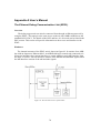
Appendix A User’s Manual ............................................................................................. 70
Appendix B VHDL-code .................................................................................................. 77
Appendix C C-code......................................................................................................... 106
1 Introduction
Debugging is an important part of software design as practically all applications
contain bugs, at least in the earliest versions. Debugging is usually done by starting the
application to be debugged from a debugging application e.g. GDB [1], which starts and
monitors the program. The most common form of debugging is called native debugging
which refers to when the debugger runs on the same hardware as the program being
debugged [2].
When the application is to be run in an embedded environment, it is often not possible
to run the debugger software on the same hardware. Then one needs to run the debugger
software on a different machine called the host, which connects to the target hardware
where the application runs. This is called remote-debugging [3]. The hardware and
software environment where the application runs needs to implement some features for
the debugger program to be able to control the execution.
To be able to perform remote-debugging, a communication link has to exist between
the host and the target. This has usually been a Joint Test Action Group (JTAG)
connection or a RS-232 connection. These connections are slow and although the
debugging itself does not require high speeds, other features are usually also present in
the remote debugging software. One example is that the program to be debugged needs to
be stored in the memory of the embedded hardware and this can often be done with the
debug software. Today, embedded hardware environments can contain several hundred
megabytes (MB) of memory and to fill them with data through a JTAG or RS-232
connection takes a long time. Also, these connections are not applicable for longer
distances (over a few meters). Thus, the target needs to be situated close to the host.
This report describes the design of an Ethernet Debug Communication Link (EDCL)
which is supposed to address these issues. Most Ethernet connections run at 10 or 100
Mbit/s, which is two to three orders of magnitude faster than JTAG and RS-232. An
Ethernet connection can also be used over longer distances on its own, but the real
advantage comes when implementing the communication using other protocols on top.
The design described in this report uses the Internet Protocol (IP) and the User Datagram
Protocol (UDP). Since IP is used as the network layer protocol on the Internet, the whole
existing network infrastructure of the Internet can be used to connect to the target. One
drawback with using Ethernet is that it is not as common on embedded hardware and
development boards as the original links. It is however increasing in popularity and the
EDCL can then provide faster debugging where available. Another problem might be that
the application one wants to debug uses the Ethernet link. This is solved by using an
arbitration scheme also developed in this project. This scheme will allow two Ethernet
connections on the same physical interface.
1
This project is a diploma thesis work part of the Electrical Engineering education at
Chalmers University of Technology in Gothenburg. The work was conducted at Gaisler
Research, also situated in Gothenburg, which has developed a System-on-chip (SOC)
Intellectual Property (IP) core library called Gaisler Research IP Library (GRLIB). The
LEON3 SPARC V8 processor, which also is developed by Gaisler Research, is included
in this library and is the debugging target. The library has previously included a RS-232
and Peripheral Component Interconnect (PCI) debug communication link for the
debugging and is now to be expanded with the EDCL unit designed in this thesis work.
The EDCL consists of two parts: one hardware part which is integrated into the GRLIB
library and one software part which handles the communication in the host computer. The
software part is integrated into the debug monitor GRMON, developed by Gaisler
Research. The software is written in the C programming language and the hardware is
designed using the Very high speed integrated circuit Hardware Description Language
(VHDL).
The report begins with some more background on remote debugging in section 2. It
continues with a description of the target technology, design environment and the
requirements for the master thesis in section 3. The description of the EDCL starts in
section 4 with a specification of the communication protocols used between the GRMON
backend and the hardware target. Section 5 continues by presenting the design of the
hardware unit. Section 6 then concludes the design phase with a description of the
software backend for GRMON. The results of the final implementation are shown in
section 6 and section 7 contains the conclusions, which ends the report.
2
2 Background on remote debugging
Two types of software debugging were mentioned in the introduction: nativedebugging and remote-debugging. This section will give some more details on the topic
which are necessary to understand the rest of the report.
Debugging is defined as the process of determining why a given set of inputs causes
an unacceptable behavior in an application [4]. The majority of all software is developed
in the same environment where it will be used and is then said to be developed in a native
environment. The most common form of debugging in a native environment is using a
debugging application, which is a tool that allows one to examine the state of a running
program from a neutral frame of reference [5]. This means that the execution path of the
debugged process (the running program) is not influenced in any way. The state of the
process is given by the CPU register values, program counter, stack and its memory-area.
The debugger normally starts the application to be debugged as a child process and
allows the user to interrupt and monitor the process in many ways. The most common
thing to do is probably to place a breakpoint in the code. This will stop the execution
temporarily when the processor executes the line of code where the breakpoint is placed.
A few other possibilities are to add watchpoints and to examine memory contents [2].
There are two major types of debuggers: machine-level debuggers and source-level
debuggers [5]. The machine-level debuggers show the process-state as low-level
constructs such as data at certain memory addresses and register values in binary or
hexadecimal format. Source-level debuggers show the state using variables and routines
as they are defined in the source code. This is done by using the information stored in the
program’s object code file.
The debuggers usually do their job well when used for debugging in a native
environment with a full-featured operating system. But as was briefly mentioned in the
introduction, things become a bit more difficult when the application is developed for an
embedded environment without an adequate operating system. As an example, the
debugger usually runs the application as a child process and stops execution with the aid
of interrupts and system calls [4,5]. This requires the presence of an operating system to
work.
Additionally, the possibilities to interact with applications running in an embedded
environment might be few even if an operating system is present. Thus, it can be a
difficult task to run the application. Applications for embedded hardware are normally
developed in a different environment and are therefore compiled and linked to an
executable on a host machine. To be able to start it, one usually includes code for a small
operating system or hardware initialization routines into the executable, which are run
before the application. They prepare the hardware for the execution of the application and
might provide a few system-calls for the application as well. The host computer then
stores the executable in the target through a communication-link. The hardware is then
resetted, which leads to an initialization of the system and startup of the application.
3
The method discussed above makes it possible to run the application on the target but
it may still not be possible to run the debugger. If this is the case one uses another form of
debugging called remote-debugging. In this method the debugger runs on the host and
connects to target through a communication-link. It communicates with the application
through some predefined communication protocol. The target application needs to
respond to the debug commands coming from the debugger through the communicationlink. One way to achieve this with serial communication using the GDB debugger is
presented in [2]. It is based on adding a few routines to the target application for interrupt
handling and serial communication. When they are included the processor can be
interrupted from the serial communication line and control is transferred to the small
debug-routine included. This way the major part of the debugger runs on the host
computer and only the necessary routines for control and information gathering are
running on the target. Source level debuggers can still be used and in this case, the object
file used for the symbolic representation is located on the host.
The target hardware and debugging-software used in this project use concepts similar
to those presented here. The details can be found in the next section.
4
3 Overview of the design environment
The debugging environment, in which the design presented in this report is integrated,
uses the general principles for remote debugging presented in the previous section. But
there are some differences in the implementation details, which will be shown in this
section. The design was made for Gaisler Research with the purpose to be included in
their existing environment. The key parts of this environment will therefore be presented
here.
3.1 LEON3
The processor in the embedded environment, on which the target applications will
run, is the LEON3 SPARC V8. It implements the SPARC V8 architecture [6] and is
developed by Gaisler Research. A detailed description can be found in [7]. It is included
in the GRLIB IP-library which will be described later. LEON3 is designed using VHDL
and is available under the GNU Public License (GPL).
3.2 AMBA-AHB
The Advanced Microcontroller Bus Architecture-Advanced High-performance Bus
(AMBA-AHB) is developed by ARM and is the main bus used by GRLIB. It is intended
for high-performance synthesizable designs. It supports multiple bus masters and the
following features for achieving high-bandwidth:
•
•
•
•
•
•
burst transfers
split transactions
single-cycle bus master handover
single-clock edge operation
non-tristate implementation
wider data bus configurations (64/128 bits)
The non-tristate implementation means that non-active units do not put their outputs
to a high-impedance state. Instead, all units have active outputs all the time and an arbiter
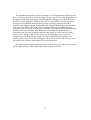
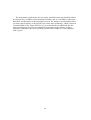
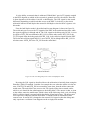
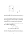
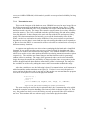
decides which of them gets routed to the inputs of the slave units. There are four types of
units on the AHB bus: masters, slaves, arbiters and decoders. Masters are allowed to
initiate data transfers but only one is allowed to use the bus at each instant. Slaves
respond to transfer requests within their specified address range. The possible responses
are OKAY, ERROR and RETRY or SPLIT. Each slave provides its own response each
instant but a decoder determines which signals get routed back to the masters. If the
response from the active slave is OKAY, it also provides data, which is routed by the
decoder in the same manner. The arbiter also decodes a select signal for the slaves from
the address provided by the active master. There is only one arbiter and one decoder on
each bus. The arbitration algorithm is not included in the specification so it is up to the
5
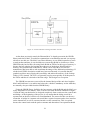
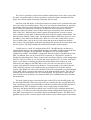
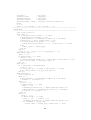
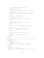
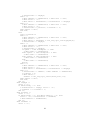
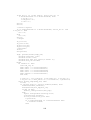
implementer to select an appropriate one for their specific design. Figure 1 shows how
the arbiter and decoder are used.
Figure 1. An architectural view of the AMBA-AHB bus showing the function of the arbiter and decoder.
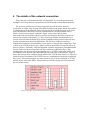
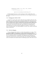
The AHB bus is intended for connecting high-performance units. For slower and
simpler devices it is more suitable to use other, less complex interfaces. AMBA provides
the Advanced Peripheral Bus (APB) intended for low-bandwidth devices. It provides a
simpler interface than AHB and with lower power-consumption. APB is typically
integrated as a secondary bus on to the AHB bus and is interfaced through a bridge,
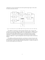
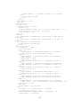
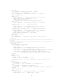
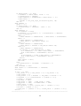
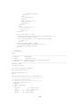
which is an AHB slave. A typical configuration is shown in figure 2 and it is also used in
GRLIB.
The AMBA-specification only defines the cycle behavior of the bus. Electrical- and
timing-characteristics depend on the implementation technology and since they are not in
the specification, it makes the AMBA technology-independent. A complete description of
the buses and all signals can be found in [8].
6
Figure 2. A typical AMBA configuration with the AHB bus connecting high-performance units and
additional peripherals connected to the secondary APB bus [8].
3.3 GRLIB
GRLIB is an IP-library that intends to enhance the development of SOC devices by
providing IP-cores with a common logistical and functional interface [9]. It is designed to
be vendor independent, expandable and easily portable between different CAD-tools [9].
A manual can be found in [10]. GRLIB is based on a collection of VHDL libraries and is
designed so that other vendors can include their own libraries. It is based on the AMBAAHB bus, presented in the previous section, with added configuration generics. The
requirement for adding new cores is that they have a unique name and comply with the
interface. A base collection of IP-cores is already provided by Gaisler Research, which
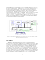
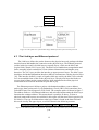
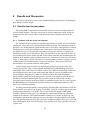
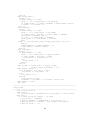
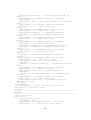
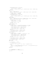
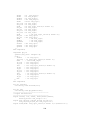
includes remote-debug support. Figure 3 shows a typical LEON2 configuration which is
identical to the GRLIB configuration on a block-schematic level. The differences lie on a
lower level.
All the cores in GRLIB so far, are written in VHDL except the Opencores MAC,
which is designed in Verilog HDL. The idea of the library is that it should be portable
between the most common simulation and synthesis tools. At the moment this includes
the simulation tools Modelsim from Mentor Graphics, NCSIM from Cadence and VSS
from Synopsys [10]. There is also some support for the GNU VHDL simulator. Support
is provided for the following synthesis tools: Synopsys Design Compiler, Xilinx XST,
Synplicity Synplify and Cadence RTL compiler. Since the models are written to support
all of these tools, it is sometimes not possible to use the language construct resulting in
the most efficient synthesis result. This is because it might not work on all the tools.
There is also technology-specific design units available such as models that, when
needed, automatically utilize block-ram on different Field Programmable Gate Arrays
(FPGA) and Application Specific Integrated Circuits (ASIC) technologies.
A short description of handling remote-debugging in embedded environments with
GDB was given in the previous section. This is not needed in GRLIB as it includes a
Debug Support Unit (DSU) in the base library. This unit is connected to the LEON3 CPU
and has the ability to put the processor in debug mode, which gives read/write access to
all registers and caches [10]. The DSU is a slave on the AHB bus and can be accessed
7
from an AHB master at any time. It also includes a trace buffer which can be used to see
the latest executed instructions. The DSU has to be accessed from a host in some way to
be able to control the debugging. The primary alternative has been to use the Debug
Communication Link (DCL), which is a master on the AHB bus and uses standard RS232 communication. The DCL implements a simple read/write protocol on the
communication-link, which is used to access the DSU. The DCL also has access to all the
other slaves connected to the bus. It is also possible to use a PCI bus through the
available PCI interface for debugging. Both these units access the DSU in the same way;
only the communication with the host is different. The host uses the program GRMON
for communication with the PCI interface or DCL.
Figure 3. A typical LEON system. The figure shows a LEON2 system but the block schematic is equally
applicable to LEON3/GRLIB systems [11].
3.4 GRMON
GRMON is a debug-monitor developed by Gaisler Research for non-intrusive
debugging on the target hardware [12]. It provides a frontend for user interactions, which
can connect to several different backends. The backends can be different communication
protocols for connecting to the actual hardware or a simulator. GRMON includes, for
example, a backend for communication with the DCL unit in GRLIB. The commands
entered by the user are converted to a sequence of AHB instructions by the frontend and
are then passed to the backend (in this case the DCL backend). The DCL backend sends
the packets, which are received by the DCL unit in GRLIB. It performs the operations on
the bus and sends a reply if needed. The replies are received by the backend and are then
passed to the frontend, which converts them back to a result for the user command.
8
GRMON includes drivers for initialization of all the cores on the current hardware
design and automatically handles the communication with the different interfaces. The
user commands are the same for all backends. Some of the features available are:
•
•
•
•
•
•
read/write access to all registers and memory
disassembler and trace buffer management
downloading and execution of LEON applications
breakpoint and watchpoint management
Remote connection to GDB
auto-probing and initialization of LEON peripherals and memory settings.
This means that GRMON is a full-featured debugger on its own. The remote
connection to GDB feature means that GRMON acts as a remote GDB target. This means
that it is not necessary to attach any of the routines to the target application, as mentioned
in the previous section, if one wants to use GDB for debugging. Instead GDB connects to
GRMON locally and the communication with the target is then handled by GRMON.
3.5 The requirements on the EDCL
With the background given so far, it is now appropriate to give the details of the
requirements on the Ethernet debug communication link. Three parts must be designed: A
hardware unit handling the Ethernet communication on the target, an Ethernet backend
for GRMON and an arbiter for sharing a physical connection between two MACs.
The first part of the requirement is that the hardware should fully comply with the
GRLIB interface. Basically, it will be an AHB master in the same manner as the DCL
and PCI interfaces and control the DSU. Because it is a master it also has access to any
slave connected to the bus (this is also true for the DCL and the PCI). The hardware unit
must be written in VHDL using a two-process method adopted for all designs at Gaisler
Research [13]. The design will make use of an Ethernet Medium Access Control (MAC)
unit, designed by Opencores [14,15], which is already included in GRLIB. More details
about Ethernet will be given in the next section and the Opencores MAC is completely
described in the hardware section. An additional requirement is that if an Ethernet MAC
is already present in the design to which the debug unit is to be attached, they should be
able to share the same physical connection. This is solved by developing an arbitration
scheme in hardware.
The second part of the requirement is the new backend for GRMON. As GRMONs
frontend always stays the same the only thing needed for the Ethernet communication is a
piece of code that communicates with the EDCL IP-core on the target hardware.
GRMONs frontend uses a standard set of functions which it calls when communicating
with the hardware core and a new set will be written so that it uses Ethernet
communication (in reality it will use the IP and UDP protocols and whatever network
connection is available on the host. This will be explained in the next section).
9
The performance requirements are not exactly specified but the unit should be able to
be connected to a 10 Mbit/s connection and if possible, also on a 100 Mbit/s connection.
Both half- and full-duplex modes should be covered. The hardware unit should be able to
run at the same frequency as the LEON3 CPU on the same technology, which is between
70 and 80 MHz for the Virtex-II FPGA [16]. Area should also be minimized after the
other constraints are met. The only additional requirement on the software is that it
should be compatible with Linux operating systems while Windows is only supported
with Cygwin.
10
4 The details of the network connection
This is the first section about the EDCL design phase. It covers the protocols and
semantics used on the network connection between the hardware unit and the backend.
The previous sections have not been completely specific about the network
connection. In reality, only the part of the network between the target and the closest host
or gateway has to be an Ethernet. This is because the IP and UDP protocols are used on
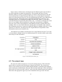
top of the Ethernet connection. Network communication is usually handled using a
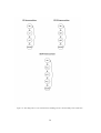
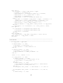
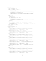
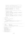
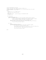
number of protocols on top of each other. Figure 4 shows the Open Systems
Interconnections (OSI) model, which is used for describing the hierarchy of protocols
involved in network connections [17]. The lowest layers handle communication on a
specific network while the higher layer protocols handle routing between networks and
control communication between applications. The OSI layer model is not always
implemented completely and sometimes, a few layers are merged into a single layer. This
is done in the TCP/IP protocol-suite, which is used on the Internet. It uses four layers as
shown in figure 5. Basically, what has happened is that the Application, Presentation and
Session layers have been merged into one layer called the Application layer. This
resulting layer has direct access to the transport layer. TCP/IP is used in the EDCL unit
for making it more flexible and addressable like any other host on the Internet. Figure 6
shows the concept of the complete design and how the TCP/IP suite relates to it. The term
protocol-suite used together with TCP/IP refers to a combination of protocols in different
layers [18]. This means that there are many protocols for each layer included in TCP/IP
and not all are used in the EDCL. The protocols used in this design will be described in
the rest of this section.
Figure 4 The OSI reference model used for describing network interconnections.
11
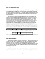
Application
Transport
Network
Link
Figure 5. The layers in the TCP/IP suite [18].
Figure 6. Conceptual view of the EDCL design and the function of the network protocols.
4.1 The Link layer and Ethernet protocol
The Link layer defines the packet format on the physical network, packages the data
into this format and handles the connection to the physical layer. The Ethernet protocol
resides in this layer and is divided into two separate layers, which are the MAC and
Logical Link Control (LLC) layers [19]. The MAC layer handles data encapsulation and
frame assembly before transmission. It also initiates transmissions and handles error
detection. The LLC layer provides the interface to upper protocol layers. The MAC layer
should use the Media Independent Interface (MII) to communicate with the physical layer
[19]. This interface defines a couple of signals which are used by the MAC layer to hand
over its assembled frame of bits to the physical layer. The physical layer then makes a
correct signal of them on the current medium. More information about the physical
connection can be found in the hardware part and in [19].
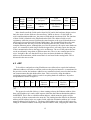
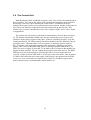
The Ethernet protocol defines a packet with destination address, source address,
packet type, data section and a Cyclic Redundancy Check (CRC) field (sometimes also
called the Frame Check Sequence (FCS) field). The complete packet is shown in figure 7.
The address fields are 6 B Ethernet addresses and each unit implementing the MAC layer
functions has a unique address. This means that it is possible, in theory, to share a
physical connection between several MACs (this report will also show this in practice for
two MACs). The type field determines what type of data is found in the data field and
this can be used by the upper layers, as will be shown in the following sections.
Destination address 6 Source address 6 Type 2 Data 46-1500 CRC 4
Figure 7. The Ethernet packet encapsulation. The numbers show the number of bytes occupied by each
field.
12
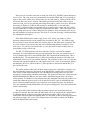
Figure 8 shows a MAC frame, which apart from the Ethernet packet also includes a
few other fields that are added at transmission. The preamble and Start of Frame
Delimiter (SFD) are used for synchronizing the two hosts in the transmission. The pad
and extension fields are added when the data being sent is smaller than the minimum
packet size allowed on the network. The unit implementing the MAC layer adds all these
fields automatically. Ethernet has both a minimum and maximum packet-size. The
maximum packet size excluding the preamble, SFD and CRC fields is 1514 B and is
called the Maximum Transmission Unit (MTU) [18]. A sometimes confusing fact is that
there are two slightly different definitions of the packet encapsulation on Ethernet
networks. There is the original Ethernet (called Ethernet II today) and the IEEE 802.3
standard. There are some small differences making them incompatible with each other
but all Ethernet networks are required to handle the Ethernet standard while 802.3 is only
optional [18]. Therefore, this design uses the original Ethernet encapsulation. More
information on this can be found in [18].
The Ethernet layer handles communication on a single Ethernet network. To be able
to forward data to another network, an additional protocol is needed, which resides in the
network layer in the OSI model.
Figure 8. The MAC frame format [15].
4.2 The network layer
The protocols in the network layer are used for routing purposes. This means that
packets can be sent between different types of physical networks. The concept is as
follows: The network layer protocol packet header and data is contained in the Ethernet
packet and begins with the header where the Ethernet data field begins. When an Ethernet
packet arrives at a host, the MAC and LLC layers strips the Ethernet header and sends the
data field to the appropriate upper layer unit as indicated in the type field. This also
13
continues up through the protocol hierarchy until only the data sent by the application in
the application layer is left. This concept is called multiplexing/demultiplexing and is
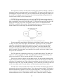
illustrated in figure 9. The network layer protocol takes the following actions when it
receives a packet from the link layer: it determines if this is the destination of the packet.
If this is the case, it strips its network layer header and sends the data field to the correct
upper layer protocol, which is determined from a field in the header. If it is the wrong
destination, the network layer protocol has some way of determining where to forward
the packet. The host can for example have a table of mappings between network layer
addresses and link layer addresses which is checked when packets need to be forwarded.
So the network layer looks up the Ethernet address of the host with the current network
layer address and resends the packet, which is done by sending a request to the link layer.
When using a network layer protocol, the router can be connected to many different
types of physical networks. For example, a packet can arrive from an Ethernet and be
directed to a Token-ring network by the network layer. The only difference from the
previous case (only involving Ethernet) is that the network layer receives the packet from
the Ethernet link layer while it sends the request to a Token-ring link layer unit instead.
Figure 9 shows an example of two different networks connected to each other. Network 1
might be an Ethernet and network 2 a Token-ring. As shown in the middle of figure 9, it
is the network layer that makes it possible to perform routing between the two networks.
Figure 9. A router connecting two networks of same or different type.
The most common network layer protocol is the IP-protocol, which is used for the
communication on the Internet. As mentioned earlier, it also the network layer protocol
used for the design in this report. The concept of IP is the same as has been presented in
the general discussion for the network layer so far. The packet encapsulation for an IP
packet is shown in figure 10.
14
4-bit
4-bit
8-bit type 16-bit total length
header
version
of service
(in bytes)
length
8-bit
16-bit
8-bit
32-bit source IP
time to
header
protocol
address
live
checksum
16-bit
identification
3-bit
flags
32-bit destination
Options
IP address
13-bit
fragment
offset
Data
Figure 10. The IP packet encapsulation [18].
More details on all the fields can be found in [18] and in the hardware design section.
Only the most relevant fields are discussed here, which are the two 32-bit fields for
source and destination addresses, the protocol field and the checksum field. The function
of these fields is identical to the Ethernet header fields. The address fields are selfexplanatory while the protocol field has the same function as the type field and shows to
which upper layer protocol the IP data field belongs. The checksum field does the same
as the Ethernet CRC but only covers the IP-header while the CRC fields covers the
complete Ethernet packet. Although the use of the IP-protocol will require more hardware
space, it is essential for achieving a flexible design since it will only require the last part
of the communication line to the target to be an Ethernet. The rest of the path to the host
can be an arbitrarily long chain of different networks. There is one essential part left to
solve. It might be the case that the IP-layer does not know the hardware (Ethernet)
address to the destination, which means that it is not found in the routing table. This is
discussed in the next section.
4.3 ARP
To be able to send packets using IP addresses one still needs to acquire the hardware
(Ethernet) address to be able to send the packet on the physical network. As mentioned in
the previous section, the hardware addresses are sometimes already stored on the host but
one cannot assume that this holds all the time. This is solved by using the address
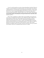
resolution protocol (ARP), which is used for acquiring hardware addresses. Its packet
encapsulation is shown in figure 11.
Hard Prot Hard Prot Op
type 2 type 2 size 1 size 1 2
Sender
Ethernet
address 6
Sender IP
address 4
Target
Ethernet
address 6
Target IP
address 4
Figure 11. The ARP protocol packet encapsulation. The numbers show the number of bytes of each field
[18].
The protocol works like follows: A host wanting to know the Ethernet address of the
host with IP address ip1 sends a ARP request which has the Ethernet destination address
0xffffffffffff. This is the so-called broadcast address, which means the packet will be
received by all hosts connected to the network. The sending host has filled in its Ethernet
address and IP address in the two sender fields, while the destination address ip1 is in the
target IP address field in figure 11. The host with IP address ip1 replies to this request by
filling in its Ethernet address in the target Ethernet address field, swapping the sender and
15
target fields, changing the op field and then sending back the packet. All other hosts
ignore the request. When the sender host receives the reply it knows the Ethernet address
and can start transmitting the data. The ARP protocol is used in the Ethernet debug unit
for advertising its Ethernet address. As it also uses the IP protocol, the intention is that
the unit is connected to with the IP address which is the standard on the Internet. ARP is
implemented for convenience since when it is used, the address translations will be
handled automatically. The alternative would be to rely on manual manipulation of the
routing tables but this is not possible under all operating systems. So to keep things
flexible, the ARP protocol needs to be implemented.
4.4 The transport layer
The IP protocol in the network layer makes sure that packets are routed to the correct host
but it does not handle such issues as flow control and packet loss. The transport layer
provides end-to-end communication control [18] and should be transparent to the upper
layers. This means that the communication semantics should be the same regardless of
the underlying layers and hardware. The transport layer handles a transmission request by
slicing the data into suitable pieces and then passing them to the network layer for
transmission. The packets are passed with different time intervals depending on how the
transmission of earlier packets proceeds. This is the flow control. Some of the transport
layer protocols also provide reliable transmissions, meaning that packets are never lost
(the upper layer part) and that they arrive at the host in order.
There are two transport layer protocols in the TCP/IP suite: the Transmission Control
Protocol (TCP) and the User Datagram Protocol (UDP). They provide completely
different services. TCP provides a reliable flow of data with data division into
appropriately sized chunks, acknowledging received packets and guaranteeing that the
other end receives sent packets in order. UDP, on the other hand, only sends packets of
data to the other end without any guarantees. Each request is sent as one packet and if it
exceeds the network MTU, it will be divided by the IP layer which is called
fragmentation. UDP also has an optional checksum. Both TCP and UDP introduce the
port concept, which has a similar function as the type and protocol fields in the Ethernet
and IP headers respectively. They identify the sending and receiving processes which are
the applications in the application layer that has transmitted and received data.
The EDCL uses the UDP protocol because of its simplicity. Since there are speed
and area requirements on the hardware it would mean a large penalty if the design uses
TCP. Since UDP is so simple, it is up to the designer to handle all the details of
reliability and flow-control. The UDP header is shown in figure 12.
16-bit source port
number
16-bit destination port
number
16-bit UDP
length
Figure 12. The UDP packet fields [18].
16
16-bit UDP
checksum
Data
4.5 The Application layer
This layer handles all the application specific details. The file transfer protocol (FTP)
for example, is used in the application layer by file transfer applications. This layer will
be used in the debug communication unit for sending the actual commands on the AHB
bus using a customized protocol. Figure 13 shows the complete packet that will be sent to
the EDCL hardware unit. The only part that is left to be defined is the application layer
header and protocol.
Since the software will be sending bus transfer instructions for the AHB bus, the
header will need to contain an address, data and a read/write bit. These three fields are
sufficient to perform transfers on the bus. A more complete description of the signals
involved in AHB bus transfers will be shown in the hardware design section. 32-bit
words are always used in the transfers and if there is more than one word in a packet, it
will be assumed that they lie on consecutive addresses with the base address in the
address field. These would be sufficient to have in the application header if only data
transfer instructions were to be sent. But as was told in the transport layer section, the
UDP protocol does not provide reliable transfer so a protocol handling this will be
implemented in the application layer instead. This protocol will be described in the next
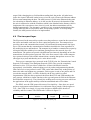
section and is called the Go-Back-N algorithm. The complete application layer header is
shown in figure 14, which also contains fields associated with the Go-Back-N algorithm.
Ethernet Header IP header UDP Header Application header Data Ethernet CRC
Figure 13. The complete packet that will be sent to the debug communication unit.
Seq
R/W Length Buf-seq Address Data
14–bits 1–bit 10-bits 7–bits 32–bits 50–242 Words
Figure 14. The application layer header. The Data field size depends on hardware parameters and the type
of packet sent.
4.6 ARQ algorithms
The definition of reliability in network transmissions is: “Data is accepted at one end
of a link in the same order as was transmitted at the other end, without loss and without
duplicates” [20]. There are a number of algorithms available for achieving reliable
connections. One class is called Automatic Repeat Request (ARQ) algorithms [21]. There
are several different ARQ algorithms and the most common are Stop and wait, Go-backN and Selective repeat [20].
4.6.1 Stop and wait
The simplest algorithm is Stop and wait but it is also the slowest. In this scheme, one
packet is sent and the sender then waits for a response before sending the next one. There
17
are two possible responses: the acknowledge reply (ACK) and the negative acknowledge
reply (NAK). An ACK is returned by the target each time it receives a packet correctly
while a NAK is sent if the packet was received incorrectly. When the sender receives an
ACK it can transmit the next packet while the current packet is resent if a NAK is
received. The sender must also use a timer since it is possible that no reply will arrive
because packets can be lost on the transmission medium. The timer is set each time a
packet is sent and if it expires before a reply is received, the packet is retransmitted.
This simple scheme is enough to fulfill the definition above but the simplicity has a
price in that it results in slow transmissions. This is because the sender has to be in idle
mode for the whole reply latency, which can be quite long. It was predicted that it would
be too slow for the EDCL and therefore ruled out of consideration.
4.6.2 Go-Back-N
The Go-Back-N algorithm is the next step from Stop and wait. It adds a sequence
number to each packet and a predefined number of packets are allowed to be sent before
an ACK reply is received. The predefined number is called the window-size. The sender
keeps all transmitted packets in a buffer until they are acknowledged. This way they can
be retransmitted if a timeout occurs or a NAK is received. The target must keep record of
the highest numbered packet for which it has sent a reply. A packet is rejected if its
sequence number is not one higher than the number stored in the target. A NAK reply is
also sent in this case and it contains the expected sequence number. When the sender
receives this NAK it restarts the transmission from the packet with the sequence number
included in the NAK (it goes back to number N). The ACK replies also contain the
number of the received packet it is sent for. An interesting thing is that not all
acknowledge replies need to be received. Since the target only accepts packets in order, a
packet can be acknowledged at the transmitter if a later acknowledge is returned. A timer
must also be present and is used in the same way as in Stop and wait.
This scheme improves speed since the sender can now continue transmitting packets
while the target is processing earlier ones. The penalty is that the complexity increases.
The good side is that it only increases significantly on the host side while the target only
needs to add a counter and a check of the sequence number.
4.6.3 Selective repeat
The Selective repeat algorithm is the most effective when the goal is high network
speed but it is also the most complex. It is the target complexity that increases the most
compared to Go-Back-N. The algorithm is the same as Go-Back-N except that when a
packet is received incorrectly or out of sequence the target sends a retransmission request
only for that packet. Thus, when an error occurs only the packets really lost are
retransmitted. The receiver also keeps a buffer in which it stores all packets received out
of sequence.
18
4.6.4 The algorithm used in the EDCL
This design uses the Go-Back-N algorithm since it gives almost as good performance
as selective repeat while keeping the target complexity down. This is important in the
EDCL because the target side is completely implemented in hardware and one
requirement is to keep the area down.
The implemented algorithm has some modifications compared to the usual definitions
of Go-Back-N found in the literature. It uses the so-called piggyback scheme. It means
that if any data is to be returned to the host as a result of a received packet, it is returned
with the ACK reply. This means that the feature of acknowledging a packet if a later
ACK is received cannot be used. If it would be used data is lost, which is not acceptable.
Another modification is the addition of the buf_seq sequence number. The seq field
contains the normal sequence number while the buf_seq field contains the buffer position
in the host from which the original packet was sent. The buf_seq field was implemented
because it was anticipated that a 14-bit sequence number would be enough and with the
other control fields there would have been 7 bits left in the 32-bit word. This was enough
for keeping count of all the buffer positions since the maximum number used in the
design is 128, which is shown in the hardware design section. Also important is that it
does not add any extra cost in the hardware since the AHB bus always reads or writes a
complete 32-bit word. The buf_seq field is then sent automatically with the rest of the
control word without any need for extra transfer cycles. The benefit of receiving the
buffer position is that the correct position in the buffer can be accessed directly.
Otherwise one would have to search from the beginning of the buffer until a sequence
number match is encountered.
Modulo counting with the sequence number is normally used for indexing the buffer.
But since packets can be retransmitted from the same position with a different sequence
number it is not possible in this scheme. The hardware design section will cover the last
details of the manipulations of the headers and other fields in the packet.
4.7 Division between hardware and software
The selection of network protocols was the most important design choice in this
project. It determines how the target can be connected to, which is an important part of
the functionality. The hardware-size and speed of the design is also largely affected by
the protocols. The requirements forced the use of the IP protocol but all the other protocol
selections have been made for achieving small hardware without sacrificing too much
speed. This has been done by using algorithms and protocols that move complexity from
the target to the host, which in this case is a movement from hardware to software. UDP,
Go-Back-N and piggyback were all selected with this in mind.
19
5 Hardware design
The hardware part of the design has been developed on the LEON-PCI-XC2V
development board manufactured by Pender Electronic Design for Gaisler Research. This
board will be described first in this section together with the existing Ethernet MAC in
GRLIB to give the reader a view of the components that were used for the design. This
will give the reader some insight into the prerequisites of the hardware design phase.
Lastly, the complete hardware EDCL will be described.
5.1 The LEON-PCI-XC2V Development Board
The main development board on which the Ethernet debug design has been tested is
the LEON-PCI-XC2V Development Board. A complete data sheet can be found in [22].
The board includes a Xilinx Virtex-II Pro-XC2V-3000 FPGA onto which all the designs
are downloaded using the JTAG interface also available on the card. The three main
input/output (IO) interfaces are the RS-232, the PCI bus and the Ethernet connection. The
Ethernet connection consists of the cable contact and the Intel LXT971A Fast Ethernet
PHY Transceiver [23], which from now on is called the PHY. The PHY is a separate chip
that handles the connection to the physical cable and makes an analog signal of the bits
transferred by the MAC layer through the MII interface. The MAC layer is implemented
in the Ethernet MAC from Opencores and is part of the design downloaded onto the
FPGA. These are all details needed about the development board in this report but more
information can be found in the datasheet if wanted.
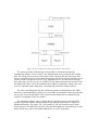
5.2 The hardware design structure
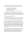
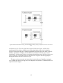
Now it is finally time to show the structure of the hardware EDCL unit, which can be
found in figure 15. The parts inside the EDCL box are the ones used for the design, which
is based on an internal AHB bus. The basic functionality is as follows: The Ethernet
MAC handles the MAC layer functions in the network protocol layer stack. When it
receives packets they are stored in buffers located in the RAM. The control-unit then
reads and processes them. It handles all the other layers in the protocol stack. If a valid
AMBA instruction has been received according to the format in figure 14, a transfer is
initiated on the external bus. The transfer is handled by the bridge, which is a unit that
reads/writes on the internal bus and writes/reads on the external bus. When the processing
is finished the control unit formats a reply packet in the same buffer position to where the
original packet was stored and then sets the MAC to transmit it. Of course there are more
details to be covered regarding the exact operation but this will be covered in the next
subsection when more general issues have been discussed.
20
Figure 15. A block-schematic showing the EDCL structure.
As has been previously stated, the Ethernet MAC is already present in the GRLIB
library and since a MAC is needed to communicate on an Ethernet network it was pretty
obvious to use this one. The MAC uses Direct Memory Access (DMA) transfers to store
or read packets and thus, it was decided to use an on-chip RAM as a buffer area. Since
GRLIB already has facilities for using block-RAM on FPGAs for this type of memory it
became the best solution for keeping down the area of the design. Block-RAM is a
memory area prefabricated on the FPGA, which is area efficient to use since the
manufacturer has been able to take maximum advantage of the fabrication technology. If
a behavioral VHDL description would have been used instead, it is possible that the
synthesis tool does not recognize this possibility and makes the memory of the Lookup
Tables (LUTs) instead. The LUTs are generally used up most quickly of all the parts in
the FPGA and thus it is desired to limit the usage. This design is no exception.
The GRLIB bus structure was used for the internal design of the unit since both the
MAC and RAM uses it. An arbiter and a decoder, which are mandatory on the AHB bus,
are naturally also provided from the GRLIB library.
Using the GRLIB library facilities, the bus structure with the RAM and the MAC was
easily designed in a few minutes. Now it can be seen from the block-schematic in figure
15 that the only part that had to be designed completely from scratch was the control-unit
and bridge. At the beginning of the project, it was meant that the bridge would be a
separate unit on the bus, but this was soon abandoned. The reason for this was the area
constraint. A bridge in a separate unit would have required a master and a slave interface
on the internal bus as well as a master interface on the external bus. This is required
because the control unit reads the packet contents and determines if an operation should
21
be performed. If this is the case it would have to send instructions to the bridge via an
AMBA slave interface. Even if one provides a few extra signals between the control unit
and bridge, which are not included in the bus, the bridge would still need an extra master
interface. By grouping the bridge and control unit in the same entity, only two master
interfaces are needed in total. The internals of the control-unit and bridge are covered in
section 5.5.
5.3 The Opencores Ethernet MAC
The Opencores Ethernet MAC is an IP-core written in Verilog HDL that performs the
MAC layer functions and is capable of operation at both 10 and 100 Mbit speed [14].
Both half- and full-duplex modes are supported. Half-duplex means that data can be sent
only in one direction at a time and full-duplex means that one physical cable can be used
for transmitting in both directions concurrently. The MAC uses the Wishbone interface
[14] to interface to the host and the MII interface to the PHY. As mentioned earlier, a
PHY is needed to make correct analog signals of the MAC data on the transmission
medium. The source-code for the MAC is available under the GNU Public License (GPL)
and can be acquired from [24].
The MII interface is defined in the IEEE 802.3 standard [19]. It is a set of signals used
for controlling the data handover between the MAC and the PHY. It consists of the
signals shown in figure 16. The clock-signals TX_CLK and RX_CLK are generated by
the PHY and provide a timing reference for all the others signals except CRS, COL,
MDC and MDIO. RX_ER, RX_DV and RXD should be synchronous to RX_CLK and
are used for receiving data. RX_DV is the data valid signal and when it is asserted valid
data is driven on the RXD 4–bit vector. When RX_ER is asserted, the PHY signals that a
receive error has occurred and that the current nibble is corrupt. These three signals are
driven by the PHY and observed by the MAC. The MAC stores the data from RXD each
rising clock-edge of RX_CLK when RX_DV is high.
TX_EN, TX_ER and TXD should be synchronous to TX_CLK and are used for
transmissions. These signals are driven by the MAC. TX_EN indicates that the TXD 4-bit
vector has valid data and should be sampled by the PHY the next rising clock edge of
TX_CLK. When TX_ER is asserted at the same time when TX_EN is asserted it means
that a coding error has occurred and causes the PHY to send data not part of the valid
frame [14].
22
Figure 16. The complete signal set of the MII interface [19].
The CRS signal is used in conjunction with both transmit and receive operations and
shows that the physical medium is busy when asserted. It is completely asynchronous and
is set high immediately when the PHY detects that the medium is busy. The collision
signal is also asynchronous and is used for both transmit and receive operations. It
notifies the MAC that a collision has occurred on the medium. If this happens the MAC
aborts any active transmissions.
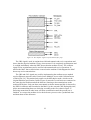
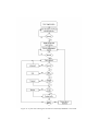
The CRS and COL signals are used for implementing the medium access method
used on Ethernet networks called Carrier Sense Multiple Access with Collision Detect
(CSMA/CD) [19]. This method only applies to the half-duplex mode, which was the
original Ethernet specification. In these types of networks several hosts are connected to
the same physical medium and all the hosts are listening to the transmissions on the
medium all the time. Only one host can transmit each time instant and this is detected by
the PHYs in all hosts and forwarded to the MACs by the asserted CRS. During this time,
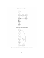
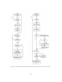
all the non-transmitting hosts are deferring according to the flow-chart in figure 17.
Deferring means that no other hosts will start a transmission until the present one is
finished. As soon as the medium is free the deference process waits a predefined time
and then shuts off the deference.
23
Figure 17. The deference algorithm used in CSMA/CD Ethernet networks [19].
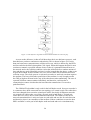
As soon as the deference is shut off (all hosts have their own deference process), each
host that has a packet to send starts a transmission. This is shown in figure 18. If more
than one hosts starts a transmission a collision will occur, which is detected by the PHYs
and forwarded to the MACs through the COL signal. When this happens the MACs must
continue to transmit a specified amount of time so that it is guaranteed that all hosts on
the network notice the collision condition. After that, all hosts defer a random amount of
time and then try again. Hopefully one host is earlier enough than the others, so that it can
acquire the medium. If this is not the case, two or more hosts start to transmit and a new
collision occurs. The whole process is repeated over and over until only one host acquires
the medium. The host, which takes possession of the medium, is early enough to make
the CRS go high on all hosts before any of the other hosts starts transmitting. The case of
repeated collisions cannot continue indefinitely and therefore, each host has a
retransmission counter which makes the host abort the transmission if it exceeds a
predefined limit.
The CSMA/CD algorithm is only used for the half-duplex mode. In newer networks it
is common to have hosts connected in a star-topology to a central switch. The cables have
also been changed from coaxial to twisted-pair cables. Practically all Ethernet networks
use twisted-pair cables today even if they are only used in half-duplex. Twisted-pair
cables have two wires, one for each transmission direction. The features in the newer
networks mean that there is only two hosts on each cable and one line for each direction
and therefore, there is no contention of the medium. If these conditions are true the host
PHYs and MACs can be put in full-duplex mode and send and receive simultaneously.
24
The carrier sense signal is now only asserted by the PHY during receive operations and
the collision signal is not used at all since collisions cannot occur.
Figure 18. The transmit algorithm used for the CSMA/CD Ethernet networks [19].
25
The receive operations work as before and the transmissions are the same except that
the MAC can assume that it is always possible to transmit without contention and can
ignore the collision signal. Deferring is naturally also not used.
One issue with full-duplex is data loss when a host cannot receive packets at the same
rate as the other host transmits them. There is no way stop the transmission by acquiring
the medium and setting the CRS high so the adopted solution is to send control frames.
These frames are generated by the MACs and have the same structure as a normal
Ethernet packet but with the value 0x8808 in the type field instead of the normal IP or
ARP values [14]. When one host wants to pause the transmission, it sends a controlframe with the op-code 0001 in the data field which indicates a pause control-frame. The
data field also contains a timer value. The destination address field in the packet is set to
the address of the MAC that should pause. When it receives this control frame it sets a
timer with the timer value in the received packet and stops the transmission until the
timer expires. The full-duplex mode does not change the interface between the MAC and
the host system. The MAC handles all the different semantics in the transfers.
Usually there is a need for configuring the PHY. The MII interface includes two
signals for this purpose: the management interface clock MDC and the management data
signal MDIO. The MAC drives the MDC and MDIO is a bi-directional signal
synchronous to MDC. The MDIO is constructed from the outputs of both the MAC and
PHY. In addition, there can be several PHYs connected to a single MAC and this is
handled by addressing them. Figure 19 shows the read frame structure of the management
interface. The write frame is very similar and can be found in [19]. As can be seen in the
figure, a read frame (excluding preamble and similar fields) starts with an op-code
followed by the address to the PHY that is to be read. The next bits select a specific
register since the PHY contains more than one. Two turnaround cycles follow this part
before the PHY with the correct address starts providing the bits from the selected
register. The MDIO line is driven by the MAC before the turnaround cycles and sampled
by the PHY whose own three-state output is in the high-impedance mode. The roles are
changed after the turnaround cycles in a read operation. The procedure is basically the
same with the write operations except that the MAC drives MDIO both before and after
the turnaround.
The only signals going to external pins (pins on the FPGA) are the MII signals. On
the development board used in the project, they are connected to the external Intel PHY
chip. The design is only tested on hardware with this board but since the MII interface is
standardized by IEEE it should be used by most commercially available PHYs.
Therefore, this design should be possible to use on all FPGA development boards and
with ASICs. Care has to be taken when deciding which configuration features to use. The
Intel PHY chip contains lot of extended features in additional registers. The IEEE 802.3
standard only specifies a control register with number 0 and a status register with number
1.
26
The operation mode of the PHY can be set with MII interface. The full set of options
can be found in [23] while this report only cover those used in the design. The operational
mode of the PHY is set by writing an appropriate word to the control register. Two bits
Figure 19. The MII Management interface read frame structure [19].
are used for setting the wanted speed mode that is 10, 100 or 1000 Mbit. Only the 10 and
100 Mbit modes are used in this design. One bit is for selecting duplex-mode and one for
auto-negotiation. There are a total of 15 bits but these are the ones used in the design.
When the auto-negotiate bit is asserted, the PHY selects the operating mode
automatically based on a negotiation procedure with the host at the other end of the
medium. When this mode is enabled the manual selection bits are not used even if they
are written to. By asserting a signal to a pin on the PHY it is possible to set it to hardware
mode and then, the operating mode is selected using three pins. In this mode the
management interface configuration is disabled.
The MII interface is always the same independent of the operating mode. The only
difference between 10 and 100 Mbit is that RX_CLK and TX_CLK runs at 2.5 and 25
MHz respectively. This results in the MAC adapting to the correct speed mode
automatically. The only change between full- and half-duplex is that the MAC ignores
CRS and COL in full-duplex. However, there are some changes in the internal functions
of the MAC which makes it necessary for it to know which duplex is active. This has to
be set manually since the MAC does not check this automatically from the PHY.
Since the transmissions have to be controlled by upper layers, the MAC has to
provide an interface with which it can be controlled. The MAC itself uses the Wishbone
interface but a wrapper is included in the GRLIB library which gives the MAC an AHB
interface. The MAC is controlled by writing to a set of registers. There are three different
main sets of registers: control registers, receive buffer descriptors (RxBDs) and transmit
buffer descriptors (TxBDs).
All the available control registers are found in [14] and only those used in the EDCL
are covered here. These registers are used for setting the overall operation mode. The
most important one is the MODER register located at address 0 of the MACs address
space. In the EDCL it is used for configuring the following parts: setting the MAC to pad
small packets, disable reception of small packets, disable reception and transmission of
large packets, enable the MACs CRC functions, set the same duplex mode as in the PHY,
not to receive packets without a proper interframe-gap (IFG), only receive packets
matching the address of the MAC or the broadcast address, send preamble before each
27
packet and enable reception and transmission. These settings will now be discussed in
detail.
In the network protocol section it was stated that there is a minimum and maximum
packet size allowed on an Ethernet network. There is one bit in the MAC which can be
set to accept packets under this limit. This feature is not used and instead the MAC uses
the value stored in the PACKETLEN register [14]. The padding feature sets the MAC to
automatically add extra bytes to a packet that is to be sent if it is smaller than the
minimum size. This will not cause a data corruption problem since each layer header
includes a field for the length of its data field and the pad bytes are therefore ignored at
reception. There is also a maximum packet length part in the PACKETLEN register,
which is used so that no large broadcast packets arrive and write over other packets in the
RAM buffer-area. If large packets are enabled in the MODER register packets up to 64
kb are accepted.
The MAC also needs to know the duplex mode, which became apparent in the PHY
discussion. This is also set in the MODER register. The MAC can automatically calculate
the Cyclic-redundancy-check value for the packet, which is selected with the CRC bit.
This checksum guarantees that the packets are transmitted without data corruption
between two MACs. The interframe-gap parameter defines the minimum time gap
between two transfers on an Ethernet. This value is specified to be 0.96 µs for the 100
Mbit mode and 9.6 µs for 10 Mbit. If a new packet arrives before the interframe-gap has
passed it is normally discarded but this can be overridden by setting the interframe-gap
bit in the MODER register. One can also skip the preamble bit pattern, which is normally
sent in the beginning of each packet. Finally, the Ethernet address handling consists of
three bits. The first is the PROMISCUOUS mode bit, which makes the MAC accept all
frames regardless of their address. The second bit is the individual address mode bit,
which selects whether the destination address in received packet should be checked
normally or using a hash-table. The last one allows broadcast packets to be rejected when
asserted. Finally, two bits are used for enabling the transmit and receive modules
respectively. These bits acts as “master” bits since one still has to enable buffer
descriptors to be able to send or receive. These descriptors will be explained later in this
section.
A few of the other control registers are closely related to the MODER register. The
PACKETLEN was mentioned in the previous discussion and contains the minimum and
maximum packet sizes accepted by the MAC if this check has not been disabled. The
MAC address is set by storing the value to two MAC address registers.
The MAC also provides interrupts, which are configured by the INT_SOURCE and
the INT_MASK register. The INT_SOURCE bits contain a few bits indicating the cause
of an interrupt. The MAC has only one external interrupt signal and the host responding
to it can check the INT_SOURCE to find out what caused it. The INT_MASK register is
used to select which of the bits in the INT_SOURCE register should cause the external
interrupt signal to be asserted.
28
Finally, there are five registers used to configure the PHY via the MII management
interface. These registers are MIICOMMAND, MIIADDRESS, MIITX_DATA,
MIIRX_DATA and MIISTATUS. MIIADDRESS is used to set the address to the PHY
and register that should be read or written. MIICOMMAND is used to start an operation,
which is either read, write or scan. If a read is performed the data is stored in
MIIRX_DATA and a write takes its data from MIITX_DATA. Lastly, the MIISTATUS
shows whether the operation failed, if the link is down etc.
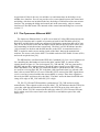
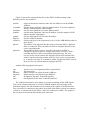
The registers covered so far sets up the basic functionality of the MAC. To start a
receive operation a RxBD needs to be enabled. The RxBDs are contained in an internal
memory-area in the MAC. Figure 20 shows the different bitpositions in a RxBD. The first
buffer descriptor lies at a predefined memory location and is polled by the MAC once the
receive bit (bit 15) in the MODER register is asserted (in practice it starts reading the
buffer located where the Rx buffer pointer points). As soon as the receive bit is asserted,
the MAC starts storing data bytes (when they arrive) to the address in the address pointer
field. When it is finished the bit 15 is deasserted. If bit 14 is asserted, a finished receive
operation will cause an interrupt. Bit 13 determines if the buffer pointer shall wrap
around to point at the first buffer again when this operation is finished or if it should
continue to the next one. There is a limited number of receive descriptors (128) so
eventually, the pointer should always be set to wrap. The rest of the bits are status bits set
by the MAC depending on how the operation went. The length field always contains the
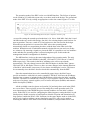
number of received bytes.
Bits
31-16
15
14
13
12-9
8
7
6
5
4
3
2
1
0
31 – 0
(2nd
word)
Description
Length of the received packet
Asserted when receiving is enabled
Asserted when a receive operation shall cause an interrupt
Asserted when the buffer pointer should start from the first descriptor after this
operation is finished. Otherwise the pointer will point at the next memory
location.
Reserved
Asserted when the packet received is a control frame
Asserted if the packet was received only because promiscuous mode was
activated
Buffer overrun
Invalid symbol
Dribble Nibble
Too long
Short frame
CRC error
Late collision
Address pointer
Figure 20. The contents of a RxBD
29
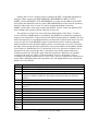
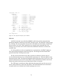
Figure 21 shows the bits in a TxBD. Their function is basically the same as for the
RxBDs. The differences are that the Length field is set before transmission and tells the
MAC how many bytes to send. Another difference is that one has two bits for enabling
padding and CRC calculation. This means that these two features can be set only for
individual packets if wanted instead of using the master bits in the MODER register.
Bits
31-16
15
14
13
12
11
10-9
8
7:4
3
2
1
0
31 – 0
(2nd
word)
Description
Length of the packet in the buffer
Asserted when transmission should begin
Asserted when a transmit operation shall cause an interrupt
Asserted when the buffer pointer should start from the first descriptor after this
operation is finished. Otherwise the pointer will point at the next memory
location.
Pad enable
CRC enable
Reserved
Underrun
Retry count
Retransmission limit
Late collision
Defer indication
Carrier sense lost
Address pointer
Figure 21. The contents of a TxBD
30
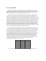
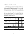
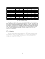
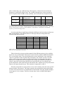
5.4 On-chip RAM
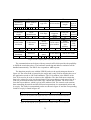
The RAM is a standard on-chip RAM from the GRLIB library, which uses blockRAM when implemented on an FPGA (at least for the supported FPGA types). In the
Ethernet unit the size can be one of those shown in table 1. The same table also shows the
buffer-sizes and window-sizes used for the different memory-sizes.
The buffer-size is equal to the maximum packet-size used in the transmissions. The
buffer-size is chosen so that it is a power of two and thus the number of buffers will
always be an integral number in all of the available memory-sizes. This makes it easier to
calculate new buffer-pointer values and in general it is easier to manage the memory. Any
power of two would not be suitable because all the layer headers use up 52 B. This would
make the efficient data rate small if small packets were used since most of packet would
be only header information. Thus it was decided that the smallest packet/buffer-size
would be 256 B. The upper limit had to be 1024 B for two reasons: The Ethernet MTU of
1500 B and that UDP was used in the transport layer. UDP always transmits the data in a
request from the application layer in one packet. Therefore, if over 1500 B is sent the
packet would be fragmented in the IP layer so that the 1500 B limit would not be violated
and this would make the processing at the target more difficult.
The window-size is always equal to the number of buffers that fit into the memory
and it was mentioned in the ARQ section. It is selected so that the memory can hold all
the packets in the buffer, which the host can send before receiving an ACK. And when
the host receives an ACK, a buffer position in the target is free again so there is always
room for the packets sent by the host-machine. This would be true if only the host
running GRMON sent packets, but there are always broadcast packets sent on a network
as well. Although the control-unit does not respond to them, they still use up a buffer
position for a short while which could possibly force the MAC to discard a packet
because of lack of buffers. However, the rate of broadcast packets should be much
smaller than the number of packets involved in the “real” data transfer so this situation
should be quite uncommon. And even if it is common it does not make the
communication fail, it only slows it down a bit.
Memory size
1 kb
2 kb
4 kb
8 kb
16 kb
32 kb
64 kb
Buffer-size
256 B
512 B
512 B
1024 B
1024 B
1024 B
1024 B
Window-size
4
4
8
8
16
32
64
Table 1. The different memory-sizes available and their corresponding buffer- and window-sizes.
31
5.5 The Control-Unit
Both the Ethernet MAC and RAM are passive units. They will not do anything unless
they are told to. The control-unit, which is the part designed completely from scratch in
this design, is the active unit controlling the whole EDCL. It initializes the MAC,
manages the memory-buffers, starts transmissions and receptions, handles all the protocol
layers above the link-layer and performs the bus transactions on the main bus. This
section will cover how it handles these tasks. The complete VHDL source can be found
in Appendix B.
The control-unit is basically a collection of statemachines, which is shown in figure
22. The Initmac statemachine (FSM) is the first one started after power-on/reset and
initializes all the control registers in the MAC. When it is finished, the MAC is up and
running and the RX_TX FSM is started which first initializes the RX_BDs and waits for
a packet to arrive. When the MAC receives a packet, its interrupt signal is asserted.
RX_TX monitors this signal and responds to the assertion by updating a few status
signals. This is seen by the Main FSM, which is running in parallel with the RX_TX
FSM. The arrow in figure 22 from RX_TX to Main is there to illustrate that nothing can
happen in Main until RX_TX sets a signal showing that a packet has arrived. The Main
FSM processes the packet stored in current buffer and if a correct packet has been
received, it either stores an ARP, NAK or ACK reply in the same buffer. Then it enables
a TxBD to the buffer and sets a status signal. If the packet is not destined for the EDCL
or a receive error is detected (seen from the bits in the INT_SOURCE register in the
MAC), then no reply is sent and another status signal is set.
32
Figure 22. The structure of statemachines in the control-unit.
The status signals set by the Main FSM after the processing is done, is seen by the
RX_TX which responds to them. When the reply is sent the interrupt signal is asserted
and since the buffer is now free, the RX_TX FSM enables the RxBD corresponding to
the bufferposition. In summary, one can say that the Main FSM processes the correct
packets and initiates the reply transmissions while the RX_TX FSM handles all the
housekeeping of the BDs and status signals. The ARP, APP, UDP and IP FSMs are only
called by the Main FSM when it needs to format the different layer headers. This was
merely a short overview and the details of each part will now be given. More detailed
state diagrams of each FSM are found in figures 23, 24 and 25.
The Initmac FSM does the initialization of the MAC in the following order: First it
sets the maximum and minimum lengths in the PACKETLEN register. The minimum
length is not changed but the maximum length is set to the buffer-size used in the RAM
that is present in the current design. This is done so that no large broadcast packets are
received, which could overwrite packets in other buffers.
33
The next part that is set is the interrupt mask. The receive frame, receive error,
transmit buffer and transmit error interrupts are enabled. The algorithm used for the
packet handling requires that the control-unit is notified both when a transfer succeeds
and when it fails. The packet handling will be explained later in this section. The MAC
address is then written to the two address registers in the MAC and lastly the main
control word is written to the MODER register. This enables the receive and transmit
functions.
When the Initmac FSM is finished, all free RxBDs are initiated by RX_TX. The
initiation uses the same part of the FSM as is used to re-enable BDs when packets are
sent. This part is included in the buffer-handling algorithm, which is rather complicated,
so it will now be described as a whole. Both the RX_TX and Main FSM are used in the
packet transfer process and they use four status registers to manage this: read_stat,
read_error, write_stat and no_snd (the names are a bit misleading as receive and transmit
are more accurate than read and write). All of them have the same number of bits as the
current window-size (equal to the number of buffers), which is determined by the
memndx generic that selects the memory-size. There are five counters used for indexing
these register: rx_offset, rx2_offset, tx_offset, tx2_offset and tx3_offset. All register bits
are set to zeros at reset except those in no_snd, which are set to ones. All the counters are
also set to zero.
Position Read_stat Read_error Write_stat No_snd
1
0
0
0
1
2
0
0
0
1
2
0
0
0
1
3
0
0
0
1
Table 2. The conceptual view of the four RX_TX status registers.
The bits at the same index position in the different registers determine the status of
the corresponding buffer position as shown in table 2. The bit in the write_stat register is
one if a receive or write operation is in progress for the buffer in the position of the index.
If this is the case the RxBD of the position will not be touched. RX_TX uses the rx_offset
counter to index this register and as soon as the write_stat bit is zero in the current
position it will go to the updrxbd states, which activates the corresponding RxBD and
increments rx_offset. This continues until a write_stat position equal to one is
encountered. Then no new RxBDs will be enabled until this write_stat position is set to
zero again.
The read_stat value is one if the position contains received data which is not yet
processed by the Main FSM, otherwise it is zero. The value is set to one at the position
that rx2_offset is pointing to when RX_TX is interrupted by a receive operation. This
happens after RX_TX has enabled the RxBDs and the MAC has received a packet. The
Main FSM polls read_stat indexed by the tx_offset counter. When the position is asserted
it starts processing the packet.
34
Read_error is set at the same time as read_stat if the INT_SOURCE status indicates a
receive error. The read_error bit is immediately checked by Main and if it is asserted, no
reply to the packet will be sent. If this is the case no_snd at the tx_offset position will be
left at one and read_error is cleared. Then Main goes back to idle and waits for a new
packet. If read_error is zero normal processing starts and no_snd is set to zero. When the
processing is finished a TxBD to this position is enabled and it is selected using
tx2_offset. A different index is used since not every packet gets a reply and if tx_offset
was used then there would be TxBDs left unenabled in the MAC. This would lead to the
MAC getting stuck at one of these BDs since the pointer is only incremented one step at
the time and thus no packets gets sent. This issue is overcome by using a different pointer
for enabling the descriptors.
If the Main FSM will not send a reply it sets write_stat to zero at the tx_offset
position so that this buffer can be enabled for reception by RX_TX. If it sends a reply
this can only be done after the MAC has sent the reply or the data can be corrupted. The
tx_offset counter is increased in the last state of Main independent of whether is to be
sent or not. Tx2_offset is increased in the wr_eth_adr2 state because at that point it is
assured that a reply will be sent.
The RX_TX FSM performs one more function, which is to check for transmit
interrupts. As was mentioned in the previous paragraph, the write_stat cannot be set to
zero for buffers that will be sent until the MAC has completed the transmission. This is
handled by RX_TX which uses the tx3_offset for locating the position which has been
transmitted when it receives a transmit-interrupt. The response to this event is to clear the
interrupt and search through the no_snd register until a zero value is encountered. When
this happens, the write_stat bit at the tx3_offset position is deasserted and the RX_TX
goes to the idle state.
The reader might wonder why all these status register are used and for example, why
the read interrupt response is not placed in the Main FSM. Actually this was tried in a
first version of the control-unit but it was concluded after testing, that it was not fast
enough for systems using 100 Mbit connections. The problem in that case is that since the
Main FSM handles the BDs no new ones can be enabled during the time it processes
earlier packets. In 10 Mbit it is no problem since the minimum time between packets is so
much larger than the typical clock cycle on the FPGA/ASIC. But in 100 Mbit the time
gap is ten times smaller and thus a lot of packets were dropped because free positions
were not enabled since the Main FSM was busy processing packet. This slowed down the
transfer enormously.
The good side of this solution is that no status registers are needed and only two
counters are needed. But since the 100 Mbit mode was to be supported, the design had to
be changed and the solution was to add a small state machine whose only task is to
monitor the interrupt signal and manage BDs. It is designed so that at each operation does
not take more than a few cycles. This change makes it possible to enable new RxBDs
while the Main FSM is processing.
35
Even if it would be possible to put the read interrupt handling in the Main FSM as far
as speed is concerned the MAC prevents this solution. The reason is that even if only the
read interrupt bits are read and cleared, the interrupt signal from the MAC will be cleared
and if there also was a write interrupt pending at the same time it will be lost. There will
also be a lot of “false” response to the interrupts since it is not known which type of
operation caused it until the INT_SOURCE register is read. Thus, when a write interrupt
occurs the Main FSM could be polling the interrupt bit and reading INT_SOURCE many
times until the interrupt is cleared by RX_TX. Figure 26 shows a flow-chart of the buffer
handling algorithm.
There are three instantiations of ahbmst entities in the beginning of the control-unit
code. These are simplified master interfaces to the AHB bus provided in GRLIB. This is
another difference from the first version which only used two interfaces, one to the
internal bus and one to the external. The new version required an additional master
interface for the internal bus to be effective. The RX_TX and Main FSM run in parallel
and this would necessitate the use of an arbitration scheme to select which one of them is
allowed to access the bus, when only one master interface is present. This could be
difficult to accomplish, require a lot of logic and reduce the benefit of having two parallel
state machines. Therefore, one additional master interface was added.
36
Figure 23. A state-diagram of the Main and RX_TX state machines.
37
Figure 24. State diagrams of the Initmac and application-layer statemachines
38
Figure 25. State diagrams over the statemachines handling the IP, UDP and ARP protocol functions.
39
Figure 26. A flowchart showing the buffer-handling algorithm. All three processes run in parallel.
40
5.6 Packet handling in the control-unit
The Main FSM does the entire packet handling for the network layers involved. The
complete IP-packet from the application is shown in figure 27 with each individual bit
presented. The corresponding packet for ARP is shown in figure 28. These figures only
show the parts stored by the MAC and they must be processed by the control-unit. The
IP-packets are the central part of the network communication since they carry the AHB
instructions. In this context “IP-packets” refers to whole packet shown in figure 27,
although it contains both Ethernet, UDP and application parts. The other type is simply
called an ARP packet although the ARP part is contained in the Ethernet data field. These
are the only two packet types that are destined for the debug unit.
The Main FSM begins with determining whether a received packet is an ARP or IP.
This is done by checking the Ethernet type field, which is 0x0800 for IP and 0x0806 for
ARP. The check is performed in the check_type state and it reads byte 12 and 13 in the
buffer but only checks the last nibble in the word. If it is a six then an ARP is received
and the next state will be the arp state, otherwise it is an IP-packet and the next state will
be check_ip. Both these packets need individual processing for the parts in the Ethernet
data field and this is performed in separate states.
Ethernet
destination
address 6 B
IP
source address
6B
0 1 2 3 4 5 6 7 8 9 10 11
16-bit total
length
16
17
16-bit header
checksum
24
25
16-bit UDP
checksum
40
41
16-bit
identification
18
19
32-bit source
address
26 27 28
29
offset 2 B
42
43
type 2 B
12
8-bit
4-bit header
type of
length
service
14
15
4–bit version
13
3-bit flags
20
32-bit
destination
address
13-bit
fragment
offset
20,21
16-bit source
port number
30 31 32 33 34
35
Application
32-bit control
32-bit address
word
44 45 46 47 48 49 50 51
8-bit time
to live
8-bit
protocol
22
UDP
16-bit
destination
port
number
36
37
23
16-bit
UDP
length
38
39
data 0-242 words
52-1024
Figure 27. The complete packet format showing all individual bits. Only the parts which are stored by the
MAC are shown. The numbers underneath the field names show the byte positions.
41
Both types have the Ethernet header in common. Therefore, both paths end up in the
wr_eth_adr state where the Ethernet destination- and source-addresses are swapped. This
is the only processing needed for the Ethernet layer because the type field in the reply
should be same as in the received packet and can thus be left as is. The reply should
always be sent to the source host and since the MAC has received the packet the
destination must also be correct and the addresses can therefore be swapped. The
processing done for each packet type is described separately in the next paragraphs.
First, the IP packets will be covered. The first thing that happens is that the
destination IP-address is checked in the check_ip state. Main goes to the check_seq state
if it matches, otherwise the packet has come to the wrong destination and the next state
will be no_snd without any further processing. The check_seq state is used for
determining if the sequence number in the packet matches the counter in the target called
rcv_nxt. This is the counter mentioned in the ARQ section. If they match, a transfer will
occur and an ACK reply sent. In the other case, a NAK will be sent and no processing is
done. A NAK/ACK bit is set according to the result of the sequence number comparison
and is used in the application-layer FSM that is entered next.
The control word beginning at byte 44 in figure 26 is read in the first state in the
application-layer FSM (app1). Then in state app2, it is determined if a NAK or an ACK is
to be sent and the appropriate state is entered. It is the control word for the reply that is to
be formatted in both cases. The R/W bit in figure 14 is used as the acknowledge bit in the
replies and if it is asserted the reply is interpreted as a NAK, thus it is set to one in the
nak state. The NAK reply should also contain the sequence number expected by the target
and rcv_nxt is therefore stored in bits 18 to 31. The last part of the word (bits 0 to 16) is
the same as in the received packet. This concludes the application layer part for the NAK
case, which now enters the finished state.
The application-layer FSM enters app3 in the ACK case and does the same
manipulations as in the NAK case but with different values. The replied sequence number
is the same as the received in this case and the R/W bit is set to zero so that it is
interpreted as an ACK. The buf_seq field is copied from the received packet while the
length field depends on if the operation is a write or read. The length is set to zero in the
case of a write operation since no data is sent in the reply. It is set to the received value
for a read operation because the number of read words is sent with the ACK. The length
is also stored in a register to aid the UDP and IP layers to calculate the length fields in
their headers, which include the application-layer as data.
A bus-operation will always be performed for an ACK reply and this is why the
application layer address field always is read and stored in a register in app3. The address
is used when the FSM enters app5 which enables the AHB-bridge part. The bridge
handles the bus-operations, which are either reading from an address on the external bus
to the internal memory or, writing data from the current buffer in memory to the external
bus. The bridge uses the master interface to the external bus and the same interface to the
internal bus as the Main FSM. Burst transfers are used to handle the operations since they
always lie on consecutive addresses and this speeds up the process significantly. A four
42
word FIFO is used for temporal storage in an attempt to keep up the transfer speed in the
case of one part being slower than the other. The application-layer part is finished as soon
as the transfer is finished. The reader might have noticed the offset field in the application
part which is not used yet. It is only there for shifting all the used data to even word
boundaries to simplify the handling in hardware.
Next in line is the UDP-layer, which is very simple. It has a source port field and a
destination port field as shown in figure 27. They only need to be swapped. The UDP
checksum is not used in this design since it is optional. This field is therefore always set
to zero according to the UDP specification. The motivation for this is that the design is
primarily intended for small LANs where the Ethernet CRC field will provide enough
data security. The errors that can corrupt data have to come from faulty routers, hubs or
other network equipment. It is highly unlikely that this will happen in small networks and
probably not in larger ones either. The length field shall contain the number of bytes in
the UDP header plus the data field. This is calculated using the app_layer_size register,
which was set in the application-layer FSM. No check is performed for checking the UDP
port since it is sufficient to know that the IP matches to know that the packet is correct.
This is since no host should be sending to this target unless it is a debug packet. The
possibility to explicitly choose a port was added to ensure that it would not interfere with
already present software in the host.
The IP layer is the last stage for IP-packets. It is bit more involved than the UDPlayer. First of all, this design only supports IPv4 and all the parts involving IP in this
report only apply to this version. There are some issues with this version which has made
it necessary to eventually replace it. The new version is called IPv6 and is not backwards
compatible with version 4 [22].
There are a lot of different fields in the IP-header but many of them are constant. The
4-bit version, 4-bit header length, 8-bit type of service, 3-bit flags, 13-bit fragment offset
and 8-bit protocol fields belong to this category. The 4-bit version determines the
currently used IP-version which is set to four (since the design is made for IPv4) and the
header-length is always five bytes since no options are used. The options field is of
variable length and there are a few features defined for it today. They are seldom used
and not all TCP/IP implementations support them [18]. This design requires that the IP
layer running on the host application (GRMON) do not add any options.
The 8-bit type-of-service (TOS) consists of 3-bits that are unused today, one that must
be zero and 4-bits with which one can select the type of service. Normal service is
indicated by four zeros and this is most common today. The TOS field is not even
supported by most TCP/IP implementations today. For this design it is required that the
host sending packets to the target use normal service and that the unused bits are set to
zero. The flags and fragment-offset fields are used when the transport layer packet is
fragmented which is avoided in this design and these fields are therefore always zero (the
IP implementation in the host must not set the do not fragment bit). The transport-layer
protocol is always UDP so the 8-bit protocol field is always 0x11 which is the
hexadecimal code for UDP.
43
The rest of the IP-fields need to be set. First the length field is the total number of
bytes in the IP header- and data- field. This is calculated from the app_layer_size register
as in the UDP layer. The identification field is a number used for identifying each IPpacket and it is normally incremented for each packet [18]. In some implementations it
could be possible to always set it to zero but it was decided to keep this feature.
The 8-bit time to live field sets the limit through how many routers a packet can pass
and is set to 64 (0x40). This field exists for eliminating the possibility of a packet getting
stuck in loop between routers. The source- and destination-address fields are swapped
before sending the reply.
The final field is the checksum field, which requires the largest computing effort of
the IP fields. The checksum field is first set to zero and the checksum is then calculated
as the ones complement of the one complement sum of 16-bit words in the IP header
[18]. This means that the IP header is considered as a sequence of 16-bit words starting
from byte 14 in figure 26 and they are then added together using one complement
addition. This is distinguished from the more common two-complement addition in that a
carry out is added back to the sum in one complement addition [26]. This has been solved
by using a 20 bit temporal register for the computation in the Ethernet design. The most
significant 4-bits are used for collecting all the carries throughout the addition and when
all fields are added these upper 4-bits are added back to the lower 16-bits. Another extra
addition is performed to cover the case when an additional carry is generated when
adding back the previous carries. The register is then complemented and stored in the
checksum field.
This rather involved calculation is the reason for the many simplifying assumptions
regarding many of the fields in the IP header. Many of the fields are constant, as was
stated in the previous paragraphs, and this means that a constant start-value containing
the one complement sum of the constant fields can be used. Then, only the non-constant
fields need to be added to this start value, which lowers hardware complexity. The source
IP address will also be constant since it is assigned to the unit using a generic value and
thus, it can also be included in the start value.
The checksum was the last part considering the IP packets and after this the main
FSM goes into the wr_eth_adr state, which was described earlier.
44
Ethernet
source address
Destination address 6 B
6B
0 1 2 3 4 5 6 7 8 9 10 11
ARP
prot type 2 B
16
17
Type
2B
12
13
prot size
1B
19
hard size 1 B
18
sender ethernet address sender IP address
6B
4B
22 23 24 25 26 27 28 29 30
31
hard type 2 B
14
15
Op
2B
20
21
target ethernet address target IP address
6B
4B
32 33 34 35 36 37 38 39 40 41
Figure 28. The complete ARP packet handed over to upper layers by the MAC. The numbers below the
name fields show the byte positions.
The ARP part is still left to be covered. It is completely different from the IP-packets
and is therefore processed in different states after the check_type state. The first thing that
is checked is if the destination IP matches and if it does not, no reply is sent and the FSM
goes to the no_snd state. If it does match, the ARP FSM is started which formats the ARP
reply. This is done as described in the ARP subsection in the Network Protocols section.
For more details regarding the control-unit, the reader is urged to take a look at the
source-code in Appendix B.
5.7 Arbitration
The requirements on the design mentioned that the EDCL design should provide the
possibility to use a MAC in the debugged design, even if only one physical interface is
available. This is solved by adding an arbiter between the MACs and the PHY. The
concept of the design is shown in figure 29.
45
Figure 29. The conceptual view showing the function of the arbiter.
The arbiter provides a MII interface to both MACs, which also includes the
management interface. The two MACs are distinguished as one main-unit and a debugunit. The debug-unit will always have equal or lower priority than the main-unit. This
choice was made because it is inevitable that packets will be lost when using this type of
scheme and this will put the error-recovery algorithms to use. It is not know at design
time, what type of error-recovery is available for the other connection but it is known for
the debug-unit. Thus, it must be tested that the Go-Back-N algorithm, which is the errorrecovery algorithm in the debug-unit, can handle the packet loss with the arbiter.
The main- and debug-unit only have different priorities in full-duplex mode. Both
units have equal probability to gain access to the PHY in half-duplex while the main-unit
always gets access in full-duplex. The reasons for this distinction are explained in the
respective paragraphs for the two modes.
The arbitration scheme is not so simple that one unit has access to all of the PHY
signals at each time-instant and the other does not. Instead the RX and TX signals are
handled differently. The clocks, TX_CLK and RX_CLK, are routed directly to both
MACs directly. The RXD, RX_DV, RX_ER and CRS signals are routed directly to both
MACs all the time, which will enable both MACs to receive all packets.
46
It is the ability to transmit that is arbitrated. Which MAC gets its TX signals coupled
to the PHY depends on which of the two units is granted access by the arbiter. How this
is done depends on if the arbiter is in full- or half-duplex. The COL signal is also routed
differently depending on which unit has access to the PHY. It is the key to the whole
arbitration scheme in half-duplex but unused in full-duplex since the MACs ignores it in
this mode.
First, the half-duplex mode is described and its state diagram is shown in figure 30.
The main-unit gets access to the TX signals of the PHY in the mainh and mt states while
the opposite applies for debugh and dt. The COL signal to the debug unit, DCOL, is set to
be equal to DTX_EN in mainh and to RX_COL in all the other states. DTX_EN is the
TX_EN signal from the debug-unit while RX_COL is the collision signal from the PHY.
The main-unit collision signal MCOL is set to MTX_EN in debugh and to RX_COL in
all other states. MTX_EN is the TX_EN from the main MAC.
Figure 30. The state-diagram for the arbiter in half-duplex mode.
By using the COL signal as described above the arbitration is basically done using the
Ethernet CSMA/CD method. Consider for example the case when the arbiter is in the mt
state. If MTX_EN and DTX_EN are asserted the same time, then the arbiter enters the
mainh state. The main MAC has access to the TX signals all the time as stated earlier,
which is as it should be but what happens to the debug MAC? The answer is that, as soon
as the arbiter enters the mainh state, which it does in the following clock cycle, the debug
MACs collision signal is asserted and it then backs off and retries later. The debug-unit
will experience collisions until the main MAC is finished with its transmission and
returns to mt. In mt DCOL is changed to the normal COL signal so that the debug-unit
only experience a collision if one happens on the real physical medium.
47
The expression, which is checked when returning from mainh or debugh, is chosen to
guarantee the proper interframe gap. It is clear that MTX_EN must be included since it is
controlling the current transfer. DTX_EN is included because the debug unit might be in
the middle of a collision event and to keep the collision signal high during this period,
one must wait for DTX_EN to be deasserted.
If DTX_EN is asserted at least one cycle before MTX_EN in the mt state the next
state will be debugh. The debug-unit gets access to the TX signals in debugh but the first
data is sampled the first rising clock-edge after TX_EN has been asserted. Therefore, the
debug unit must get access to the TX signals in mt as soon as it is determined that
DTX_EN=1 and MTX_EN=0 holds. The debugh and dt states are identical to mt and
mainh with the role of the debug-unit and main-unit interchanged.
Figure 31. The state-diagram for the arbiter in full-duplex mode.
The state-machine controlling the arbitration in full-duplex mode is shown in figure
31. Here, as can be seen in the figure, the main MAC will always be able to transmit
regardless of whether the debug-unit transmits or not. This is because in full-duplex
mode, the CRS and COL signals are ignored by the MAC since there should be no
contention for the medium. It is therefore impossible to stop a transmission from the
MAC externally. The main MAC was chosen to have priority so because of that, it will
always be able to transmit.
The TX signals are coupled in the same way as in half-duplex mode. The main unit
signals are always coupled to the PHY when MTX_EN is asserted and the debug unit
gets access when DTX_EN is asserted and MTX_EN is deasserted.
There are two issues to discuss for full-duplex mode. The first is that the debug-unit
can be interrupted in the middle of a transmission. This means that the packet will be cut
off before it is completely sent. This will not be a problem since the last four bytes will be
interpreted as the CRC value and the probability for it to match the part of the packet sent
so far is incredibly small. Thus the packets will be discarded and no harm is done.
The other issue comes from the same source and is that the interframe-gap cannot be
guaranteed to always hold with this scheme. This is because the main MAC will begin to
transmit immediately regardless of the state of the debug MAC. The debug-unit can also
start to transmit as soon as the man-unit is finished without a long enough gap. The
solution adopted is to use a FIFO-buffer with 25 entries. When the master is changed
48
from main to debug or the other way, the TX_EN is first set to zero for 25 cycles and the
values coming from the active MAC are stored in the buffer. The TXD, TX_ER and
TX_EN values are stored. When 25 cycles have passed the values from the buffer are
used as outputs. This will guarantee that a proper interframe-gap is always achieved.
Since the TX_CLK and RX_CLK speeds depend on the network speed it could be
quite troublesome to get the arbiter working if it was clocked with the main-clock since
its frequency is not known in advance. The idea is to use the TX_CLK as the clock in the
arbiter instead since then, the arbiter will automatically adapt to the current operating
conditions and it will also be known what the frequencies will be. It is also simpler to
design the FIFO-buffer used in the full-duplex mode. It could be very tricky to solve this
with the main-clock.
Finally, the management interface arbitration is covered. Actually no run-time is
performed for these signals since it would be too complicated. Instead the mdiomaster
generic is provided which allows one to select which MAC has access to the management
interface in each implementation.
49
6 Software design
This section covers how the Ethernet communication backend for GRMON was
made. This description will be somewhat different from the hardware section since
GRLIB is under the GPL license while GRMON is under a proprietary license. The
source code for the Ethernet backend can therefore not be published and all the details of
GRMONs functionality cannot be explained. Some flow-charts will be used in the
explanation.
The function of GRMON was explained earlier in the report. The commands it wants
to perform are handed over to backend in the form of an address and a pointer to the data
and a read/write variable. It is then up to the backend to make sure that it is performed on
the hardware.
The purpose of the Ethernet backend is to accept the command from the frontend,
encapsulate it in the data field of a UDP/IP packet and send it to the host. The
transmission should be done providing reliability, which is done by implementing the GoBack-N algorithm in the backend.
First, the method to send IP and UDP packets is presented. GRMON runs on
UNIX/LINUX operating systems and only provides support for Windows running
Cygwin, which is a Linux-like environment for Windows [27]. There are two common
Application Programming Interfaces (APIs) for network applications in UNIX: Sockets
and STREAMS. This design uses sockets, which was selected because it is the most
common of the two. Even Windows has its own native socket implementation but the
programming interface is unfortunately not completely the same.
The socket interface is a collection of system calls abstracting the details of the
network hardware and protocol implementations from the user. Figure 32 shows the basic
concept of the interface. The user uses simple system calls and chooses which protocols
to use and the socket layer handles the rest. It calls the part of the kernel code handling
the requested protocols, which encapsulates the data in the correct way. When this is
finished the network interface, which can reach the host with the destination IP-address,
is used to send the packet. An ARP might need to be sent if the target is on the local
network but no entry is found in the routing table. This is also handled automatically by
the kernel code.
50
Figure 32. Overview of the Socket abstraction model.
To use the Socket API for UDP and IP two things must be done. A socket must be
opened and the target address must be set. The first part is done using expression (1) [28].
host_sock=socket(AF_INET,SOCK_DGRAM,0);
(1)
Host_sock is a normal integer which works like a handle to the correct socket in the
socket layer. It is later used when data is sent. The first parameter selects the format of
the protocol address. In this case it is AF_INET which means 32-bit IP addresses [28].
The second parameter selects the communication type and for AF_INET, this indirectly
also selects the protocol. SOCK_DGRAM selects UDP while SOCK_STREAM would
have chosen TCP. The third parameter selects the wanted protocol if many are available
that implement the connection type requested in parameter two. There is only one
protocol available in most systems so the third parameter can usually be left as zero.
There is a generic socket address type called sockaddr used by the kernel for storing
most addresses. There are also protocol specific address types and it is called sockaddr_in
for AF_INET addresses. It is defined as in figure 33.
struct sockaddr_in {
short
sin_family;
u_short
sin_port;
struct
in_addr sin_addr;
char
sin_zero[8];
}
Figure 33. The definition of the sockaddr_in structure [25].
The sin_zero field is added to match the size of the generic sockaddr structure.
The sin_family variable should be set to AF_INET, sin_port is the port number of the
target and lastly sin_addr is set to the destination IP-address. The last two parameters can
be set as generics in the VHDL code for the hardware. There are functions available for
51
converting an IP-address in dot format to an integer. The function used here is called
inet_addr().
These are the only initializations needed and it is now possible to start
sending/receiving. The sendto system call is used for transmitting while recvfrom is used
for receiving. They always try to send the message in one unit and if this is not possible
on the current physical network they will return with an error-code. The format of these
system calls are shown in expression (2) and (3).
int sendto(sd, msgbuf, len, flags, to, addrlen)
(2)
Sendto returns the number of bytes sent. The different parameters have the following
functions: sd is the socket handle which in this case should be host_sock, msgbuf is a
pointer to the data structure containing the data to be sent, len is an integer holding the
number of bytes to be sent, the flags field can be used to select some special features but
is not used and is therefore set to zero in this design, to must be a pointer to a sockaddr
structure containing the destination address and addrlen should point to an integer
containing the number of bytes in the address. The address parameter must be a generic
sockaddr stucture so a typecast must be done from the AF_INET type sockaddr_in.
int recvfrom(sd, msgbuf, len, flags, from, addrlen)
(3)
The return value and most of the parameters for the recvfrom system call are the same
as for sendto. The difference lies in the three parameters len, from and addrlen. From is a
pointer to a sockaddr structure containing the source address after the transfer is done.
Addrlen is a pointer to an integer containing the size of this address. Len is now a pointer
to the msgbuf length instead of the number of bytes it actually contains. In the case of an
error condition, both calls return –1 and sets errno to an appropriate value.
This covered everything needed to be able to send UDP/IP packet from an UNIX
environment. If the destination IP is located on the network connected to the Ethernet
interface on the host, the packet will also automatically be sent on it. It must still be
figured out how to schedule the transmissions in an efficient manner.
The Go-Back-N algorithm will be used for the flow-control as was mentioned in the
ARQ section. How this is done will only be shown in a flow-chart not unveiling any
details because of the reasons mentioned before. The implementation is based on the
select() function call [29] and two counters: snd_nxt and buf_seq. Snd_nxt is used for
numbering all packets with a sequence number and buf_seq is used for identifying which
buffer position the packet is in.
It was mentioned that when using the Go-Back-N scheme, the unacknowledged
packets need to be stored in a buffer in case they need to be retransmitted. This could
have been done using snd_nxt modulo the buffer-size but this would be somewhat
difficult since new buffer positions would have to be allocated in some cases when
retransmissions occur. This is due to the fact that the retransmitted packets will not get
52
the same sequence number as the original one. The implemented algorithm always
assumes that the replies have been lost in the case of a timeout and the sequence numbers
should not be reused in that case. This is because if the packets have been received, the
rcv_nxt counter has been incremented and sending with the same sequence numbers
would only lead to NAK replies. The reason for this choice is that this situation appears
to be more common than the other. If the sent messages have been lost instead, a NAK
would be received directly.
By using an independent counter for keeping track of the buffer position the
retransmissions can be handled in a simpler manner. A 14-bit sequence number suffices
to achieve reliability since it allows 16384 packets to be sent until the counter wraps
around. As was mentioned in the hardware section, this left some space for the buf_seq
field, which therefore does not give any extra hardware cost.
The buf_seq field is sent with the packets and is always returned unchanged. This
means that the buffer does not have to be searched for a sequence number match. If this
extra number was not used, each time a packet is received one would have to start
searching from the first unacknowledged position.
The last issue to discuss is efficiency. It is also desirable to get the application
running fast. The trouble is that the sendto and recvfrom system calls block until they are
able to send or receive something. Then one could get stuck waiting for receiving packets
and during this time, it could be possible to send packets instead. One must also
implement timeouts, which were mentioned in the Go-Back-N section. The first solution
thought of was to use threads and signals. One thread could be used for transmitting and
one for receiving. The timeouts could be solved using a timer, which sends a signal when
it expires. This signal can then be set to be handled by a specific function when caught
[29].
There are however, some problems with this solution. First, GRMON should be
portable to a few different operating system environments and there are often different
thread implementations in each of them. The other issue is that signals are already used
elsewhere in GRMON and this could cause trouble.
The final solution was to use the select() system call instead [29] which solves both
these issues and is shown in expression (4).
int select(int nfds, fd_set *readfds, fd_set *writefds,
fd_set fd_set *errorfds, struct timeval *timeout);
(4)
The select call tests whether any of the file/socket handles given in the parameters
readfds, writefds and errorfds are ready for reading, writing or has an error condition
respectively. It blocks until one is ready or until the timeout value given in the timeout
parameter has been reached. If no value has been given (the parameter is NULL), the
select call can block indefinitely. The nfds specifies how many handles will be checked
and should be set to the largest handle in the fds parameters plus one. As may be recalled,
the socket handle is merely an integer.
53
The readfds, writefds and errorfds are fd_set structures and contain the handles that
should be checked for a blocking condition for the different operations. A handle in
readfds is checked for a blocking read condition, a handle in writefds is checked for write
conditions and errorfds is used for error conditions. Only the host_sock handle is used in
this design and it is checked for all three conditions. Then for example, it can be added to
the writefds structure as in expressions (5) and (6).
(5)
(6)
FD_ZERO(&wfds)
FD_SET(host_sock,&wfds);
Wfds is declared as a fd_set and the function FD_ZERO then makes it an empty set.
The host_sock is then added to wfds by calling FD_SET as in (6). This done in the exact
same way for read and error sets. The struct timeval contains values for the delay in
seconds and microseconds. This is shown in figure 34. It is initiated to the wanted values
and a pointer to it is then added in the call to select.
struct timeval {
time_t
tv_sec;
/* seconds */
long
tv_usec;
/* microseconds */
}
Figure 34. The timeval structure used for specifying timeouts in the select function [26].
A complete call to select for this design might then look like in expression (7) where
host sock has been added to all three fd_sets.
select(host_sock+1,&rfds,&wfds,&efds,&timeout);
(7)
These are the basic functions used in the Ethernet backend. Figure 35 contains a flowchart showing a simplified structure of the program. The first two parts are the
initialization parts. First the user is asked to enter the IP-address and UDP-port they have
chosen for their hardware. Then, these values are used for initiating the socket and target
address structure as was shown above. After that the backend is idle until the frontend
sends a transfer request. When one arrives the backend immediately calls select and when
it returns all the operations that will not block are performed. First it is checked if none is
available and if this is true, a timeout has occurred. If this is the case, the transmission is
set to restart from the first unacknowledged buffer and select is called again. The
different operations are then checked in the order shown in figure 35. The program will
exit in the case of an error condition since this should not happen and indicates a problem
in the protocol stack or the device driver. If a transmission is non-blocking a packet will
be sent using the sendto system call. The next check is for a receive operation and if it is
non-blocking a packet will be received with recvfrom. The last part is to update the
buffer and store data if a packet has been received. Then, if the whole transfer is finished,
data is returned to the
54
Figure 35. A flow-chart showing how the Ethernet backend for GRMON is structured.
55
frontend if it was a read and the backed goes back waiting for a new request. If it is
not finished a new select call is done and more packets are transmitted/received.
Lastly, it will be explained how the fields in the application layer are set. The snd_nxt
counter has already been mentioned and is used to assign the seq field in the control
word. The read/write bit is constant during a transfer and is set according to the operation
wanted by the frontend. The total length of the data to be sent/received is given by a
parameter. The backend starts transmitting by filling up the data field in the first packet.
The packet is sent when it is full or no data is left. If there is data left another packet will
be sent and the same procedure will be repeated again. The length field for each packet is
set when the buffer is filled. The buf_seq field is set to the number of the buffer position
that the packet is taken from. The length, r/w and buf_seq fields will stay the same during
the whole lifetime of the packet while the seq field is changed if timeout occurs or a NAK
is received.
When a packet is received, it is first checked if it is a NAK or an ACK by looking at
the r/w bit. If it is a NAK the sequence number is updated and a retransmission begins. If
it is an ACK the buffer is indexed by buf_seq and it is checked if the sequence numbers
matches. If they do, the received packet is accepted and the buffer is labeled as
acknowledged when data is saved. The sequence number check must be done since an
older packet from the same buffer position might have been stuck somewhere in network,
thus arriving late. The length field is used for determining how many data words are to be
read from the received packet if it is a read reply.
This is all that is going to be revealed about the backend. Any more details would
uncover too much of GRMONs structure. Hopefully, this has still given a basic
understanding of how the Ethernet communication is handled.
56
7 Testing
This section will cover how the design was tested. A pretty traditional approach was
used for the hardware with an initial simulation phase followed by hardware test. The
software was only tested during the hardware test-phase.
7.1 Simulations
The purpose of the simulations was to check that all the basic functions in the
hardware worked correctly. Since it is virtually impossible to recreate all the situations
that might occur when running on real hardware the tested cases ended up being pretty
simple. The following was tested:
•
•
•
•
•
•
•
ARP request with correct IP
ARP request with wrong IP
Write instructions with different number of words
Read instructions with different number of words
Read/Write instructions with wrong IP
Read/Write instructions with wrong sequence number
Transmission of enough packets to make all the offset counters wrap around.
These tests were conducted for different combinations of the generic parameters
affecting the function, which are the memory size, IP address, UDP port etc. The
simulations were done in the program Modelsim [30], which provides a
VHDL/Verilog/SystemC simulation environment. The simulations were done using a
testbench which instantiates the EDCL unit and a simple VHDL model of the PHY. The
PHY is only able to receive and transmit nibbles, no management interface is provided.
One can select between 10 and 100 Mbit operation which sets TX_CLK and RX_CLK to
the correct values.
Figure 36. The connection of different components in the testbench.
The structure of the testbench is shown in figure 36. The PHY provides the normal
MII interfaces through which it is connected to the debug-unit. The testbench provides
clocks for the two components and a few other constant configuration signals. The PHY
57
gets its indata from an indata file containing packets in the form of a sequence of binary
nibbles in text format. There are basic VHDL constructs available for reading text and
converting it to bit-vectors. This was a pretty simple and fast method to get the
simulations running. The replies from the debug-unit are stored back into a data-out file
in the same format. A C-program called makeindata was written which automatically
made the indata file as wanted. It has the following parameters: Ethernet address, IP
address, UDP port, read/write, win-size, block-size, number of packets and AHB address.
There is also a program called readdata which extracts the most interesting
information such as packet type and sequence number from the data-out file. The sourcecode for both these files are found in Appendix C. The PHY and testbench source-code is
found in Appendix B. The arbiter was tested in the same manner using almost the same
testbench with the changes shown in figure 37. The data-in file was also changed in this
case to contain packets for the two different targets intermixed.
Figure 37. The testbench used for testing the arbiter.
7.2 Hardware testing
There are three different parts of this test phase: the transmission tests, debugging
tests using two MACs with an arbiter and software debugging. They will be covered
separately although they were performed in parallel. The design was synthesized using
Synplify while it was place & routed using the different tools provided in the Xilinx ISE
suite. The design was implemented on the Virtex-II Pro FPGA on the Leon-PCI-XC2V
Development Board. It was connected to a host PC running Slackware Linux, with a
serial cable and an Ethernet connection.
The implemented design was a typical GRLIB system containing a LEON3 CPU, a
memory-controller for getting access to the SRAM and SDRAM chips on the board, a
trace-buffer, a RS-232 DCL, on-chip RAM and the EDCL. The memory-controller gave
58
access to 64 MB of SDRAM, which made it possible to test speed and reliability for long
transfers.
7.2.1 Transmission tests
This was the first part of the hardware tests. GRMON was used to store image files to
the different memories in the hardware using the load command. Large files (> 1 MB)
were stored in the SDRAM. The verify command was used to check that the image file
had been stored correctly. The image files contain a specification of were they should be
stored in memory. The verify command reads the specified image file and starts reading
from the addresses. It then compares the retrieved data with the file and reports if they
match. This data transmission test basically covers all the functionality since all the
EDCL can do is to read and write on the AHB bus. If any more actions are performed
depends on were the data is stored and how the unit owning the address area responds to
it. But as far as the EDCL is concerned it suffices to be able to read and write correctly to
different memory locations.
A separate test application was also written containing the backend and a simplified
frontend. It was used to test the error-recovery of the Go-Back-N algorithm and a few
changes were made to the backend for this purpose. Two random variables were added
which were used to select when packets should be lost during transmission and reception
respectively. The variables are normal integers and the function used for generating
random values is random(). The range of the generated values can be selected and the
larger the range the smaller the probability of dropped packet since zero means a packet
shall be dropped and all other numbers mean that a packet is let through. The range for
the variables are achieved by taking the return value from random modulo the range.
After the variables are set, the following is done. For transmissions, an if statement is
added around the sendto statement as in figure 38. If wlost is set to zero the packet is
never sent but all the other code is run just as if the packet was sent and thus the program
will run as if the packet was lost on the physical medium.
if(wlost==0) {
result=1;
} else {
result=sendto(sd, msgbuf, len, flags, to, addrlen)
}
Figure 38. The code used for emulating lost packets at transmission.
The same concept is used for the reception but here, the if statement has to be added
around the complete reception handling code instead, which is shown in figure 39. This
way, the packets are always received but they are only processed if the rlost variable is
not zero. This emulates the case when a reply is lost on the physical medium.
59
recvfrom(sd, msgbuf, len, flags, from, addrlen)
if(rlost!=0) {
/*receive handling code*/
}
Figure 39. The code emulating lost packets during receive.
The data-transmission tests were also run using two MACs and the arbiter. The
application emulating packet loss was not used in this case since it happens inherently in
the arbiter.
7.2.2 Debugging tests with two MACs
A special test was also made with the arbiter and only one Ethernet debug-unit. The
other MAC was on the main bus and was used by the LEON3 CPU. The test was done as
follows: GRMON uses the Ethernet backend and downloads the ttcp application in the
form of an image file to the target. The application was then started from GRMON using
the run command. The ttcp application uses tcp communications and accepts transfer
requests from a client. Thus it uses the MAC on the main bus for communication. A
client ttcp process was started on the host computer and a transfer of a large file was
started. While this transfer was running GRMON was used to stop, continue and step the
target ttcp application.
7.2.3 Software debugging
The only debugging of the software was done during the hardware test phase. When
the program crashed or a functional error was discovered the program was either
debugged with GDB or by commenting out suspected parts. The debugging in GDB was
done by running the application from GDB and doing the same transfers that caused the
error or crash in the first place. Breakpoints were added before the points that were
suspected to cause the errors. In some cases the bugs were not found by using GDB for
some reason and then, the manual method of commenting out parts of the code was used.
60
8
Results and Discussion
This section will present some results obtained during testing and also such things as
area and speed of the design.
8.1 Results from the test phase
The testing both in simulations and on hardware uncovered several bugs and more
serious design mistakes. The bugs uncovered, to which solutions have been found, are
discussed in the first section. The second section describes problems still left in the
design.
8.1.1 Problems with the design and solutions
The simulations uncovered lots of smaller bugs which were easily fixed. Overall, the
simulations were pretty easy compared to the hardware testing. The simulations made it
possible to see all the internal signals and the source of the bugs could quickly be located.
The bugs uncovered in the simulations were more often of the simpler kind because of
the simple test cases. It is practically impossible to create the same flow of packets in
simulations as they occur in hardware. This is because the real flow depends on more or
less random packet losses on the network, which affects timeouts and retransmissions. In
addition, there might be many broadcast packets on a real network which also affects the
target. A final reason is that it can require several thousands of packets to trigger an error
condition and such simulations take a long time to perform. Thus most of the issues
discussed here are from the hardware-testing phase.
A major design issue was discovered during the hardware test phase of the first
control-unit version. This version included the RxBD and TxBD handling parts in the
Main FSM. This worked fine in 10 Mbit/s with its slow PHY-clock and large interframegap compared to the clock in the control-unit. But when it was run in 100 Mbit/s the
speed suddenly dropped from 5 Mbit/s to 200 kbit/s. More thorough simulations
uncovered that a majority of the packets were rejected at the target because the MACs
RxBDs had not been enabled again. This was due to that the control-unit was busy
processing earlier packets in the main FSM. As mentioned earlier, the fix was to separate
the BD handling to a separate state-machine with its own AHB master-interface. This
also led to a small area penalty.
The design also had frequency issues initially. Recalling the requirements section, the
debug-unit has to be able to run at about 70-80 MHz. The first version tested for this only
managed approximately 55-60 MHz. This was due to the fact that the AHB master
interface contains several logic levels and that the control-unit did not use registered
outputs to the interface. This situation and the solution to it is shown in figure 40. The
worst paths found from the synthesis tool were the address and data signals to the AHB
bus. The idea that came up to fix this was to precalculate the address, data, size, burst and
other AHB signals in the cycle before they were actually used. They were then stored in a
register and
61
Figure 40. Block-schematic showing the ídea behind the change fixing the frequency issue in the controlunit.
used the next cycle. The only signal not registered is the start signal, which is kept
combinatorial to be able to respond to the ready signal in the same cycle it changes.
Figure 41 shows the old type of signal assignments while the code in the final version is
found in Appendix B. In figure 41, the addresses calculated in check_seq are used
immediately, which means the have to propagate through the master interface in the same
cycle. In the new version the values are first stored in a register and then propagates
through the master interface in the next cycle.
The new version was tested and immediately reached the goal. Initially it managed
over 80 MHz but after a few bug-fixes were adopted it was down at 75 Mhz but still over
requirement with margin.
62
when check_seq =>
dmao.address:=r.base_addr+44; dmao.write:='0';
dmao.size:="10"; dmao.start:='1';
if dmain.ready='1' then
dmao.start:='0';
if dmain.rdata(31 downto 25)/=r.rcv_nxt then
v.main_state:=app; v.nak:='1';
else
v.main_state:=check_tx_bd;
v.rcv_nxt:=r.rcv_nxt+1;
end if;
end if;
Figure 41. A code fragment showing the AHB signal assignment method in the old control unit.
Another major bug was found which corrupted data when writing. This bug took
quite some time to fix since it was believed that the error was in the hardware. The
problem was at that the end of some packets was written incorrectly. The reason for
believing that the error was in hardware was that the transmitted packets were checked
using the Ethereal application and seemed to be correct. But the check was not thorough
enough, which is quite natural since there were thousands of packets that had to be
searched manually. Lastly after four days of testing it was discovered that the number of
incorrect bytes was the difference between the maximum packet-size and the size of the
last packet sent before a timeout. The bug was finally found to be that the len parameter
to the sendto function was not reassigned after timeouts. Thus if the last packet sent
before a timeout was smaller than maximum size, then all maximum size packets sent
after a timeout did only send the number of bytes in the last-packet before the timeout.
Therefore, there was old data left in the target memory when the control-unit started its
transmission. The bug was easily fixed when discovered.
8.1.2 Unsolved issues
There is an issue with the arbiter design. The problem is the clocking method which
uses the TX_CLK as its clock. This was tested and worked fine when Synplify was used
for synthesis, but the Synopsys DC tool did not accept the construct. This was because
TX_CLK is part of a record. The arbiter therefore has to be rewritten if it is to be used
with Synopsys. Since the main-clock has to be used instead it can be very tricky to get the
arbiter to work for all possible clock-frequencies that the design might run on. This is
because the master change has to be quick enough (because of the signal source change)
and the FIFO-buffer has to be long enough to guarantee the interframe-gap. No solutions
are provided to this issue here.
When the first tests were done at 10 Mbit/s full-duplex it was quite annoying to find
out that when writing to the target the speed was up at 5 Mbit/s but when reading it fell
down to 100 kbit/s. Several days were used to find the reason but none was found. Then
the AHB trace-buffer for GRLIB was completed and was taken into use. It is able to store
several thousands of AHB transfers and add breakpoints on certain addresses. With the
aid of this unit, it was discovered that the MAC did read the packets that were lost from
63
memory but they never appeared at the host. What happens in the MAC in this case is
still a mystery. The reason for the slow speed in the reads was because only replies were
lost and the Go-Back-N can acknowledge earlier packets if a later acknowledge is
received when no data is sent with the reply. This is not possible when reading since the
data is sent piggyback with the acknowledge. This means that a lot of retransmissions
have to be made when reading and thus the low speed.
The 100 Mbit/s mode is still quite unstable. It works both in half- and full-duplex and
with an arbiter but it hangs sometimes and has a large frequency dependency on the
speed. The full-duplex only runs at normal speed when the frequency on the chip is 60
Mhz or above. The actual data rate of the half-duplex mode increases with frequency but
it does not work at all under 50 Mhz. This was discovered earlier at Gaisler Research and
is a limitation in the MAC. Some posts in the Ethernet MAC forum indicate that there
might be issues above this frequency too [31].
The 100 Mbit/s version was first tested in a hardware design were the debug-unit
components were connected directly on the main bus which worked fine. But when they
were made into a single module with an internal bus the speed dropped down to under 1
Mbit/s. This is contradictory since this change should increase speed since the unit now
has its own bus with less contention of the cycles.
8.2 Design data
Despite all the problems discussed in the previous sub-section, there is still a fully
functional design available. The currently released version is locked to 10 Mbit/s halfduplex. With locked it is meant that some of the generics for choosing the operating
mode has been removed so that the unit cannot be set to the unstable modes. The current
situation for the different operating modes is presented in table 3.
The average approximate speed values are based on the observations made during
testing and debugging phase. The values are reported by GRMON, which always gives a
speed indication during transfers. No scientific record keeping have been made of the
values observed and no accurate mean has been calculated. The values merely show a
mean based on a few observations made. They should however be accurate for 10 Mbit/s.
100 Mbit/s is more difficult since it was so fast that even the largest available image files
were often downloaded so fast (under one second) that no measurement was made by
GRMON. The files were however, approximately 2.4 MB so the 20 Mbit/s value is a
lower bound on the speed.
All the operating conditions are more or less unstable except 10 Mbit/s half-duplex.
There is a question mark regarding this for 10 Mbit/s full-duplex since the only problem
with it is the slow speed when reading. But the design should work perfectly to qualify
for a stable entry in the condition column. The arbiter column shows whether the
operating mode works without trouble with an arbiter. An operating mode immediately
receives a no for the slightest problem observed. The 100 Mbit/s versions for instance
64
often work but they may suddenly hang. The frequency column shows the minimum
frequency for which the design works. The 10 Mbit/s designs have not been tested for
lower frequencies than 40 Mhz so they probably work for much lower frequencies too.
Duplex-mode Speed
Mbit
10
Half-duplex
100
10
Full-duplex
100
Approximate effective
average speed
5.5 Mbit/s
20 Mbit/s
5.5 Mbit/s
20 Mbit/s
Condition Arbiter Frequency(2)
stable
unstable
unstable(1)
unstable
yes
no
yes
no
40 Mhz
53 Mhz
40 Mhz
60 Mhz
Table 3. The current status of the different operating modes. The average speed is only based on
observations during the test phase. Unstable means that the design works badly and/or hangs. (1)The design
always works but it is very slow in certain conditions. (2)The frequency column shows the minimum
frequency for which the design works.
It can be noted that no significant performance difference has been observed between
half- and full-duplex. This indicates that it is the target side processing and/or busutilization that limit the speed.
Memory-size (kb) Window-size Block-size Average-speed
1
4
256
3.8 Mbit
2
4
512
5.5 Mbit
4
8
512
5.5 Mbit
8
8
1024
6.5 Mbit
16
16
1024
6.5 Mbit
32
32
1024
6.5 Mbit
64
64
1024
6.5 Mbit
Table 4. The average speed measured for different memory-sizes in 10 Mbit/s mode. The window- and
block-sizes are repeated for convenience.
Table 4 shows the average speed measured for the different memory-sizes available.
Again, the way in which these values have been measured would not fulfill the demands
for a real scientific study. They should instead be seen as indications. If one trusts the
values it is possible to draw an interesting conclusion. The window-size has very little
effect on the average speed while it seems as if the block-size determines the speed
differences. It might be worth clarifying that the average-speed numbers presented are
effective data rates, which means that the bytes in the headers are not counted in the
speed calculations. This means that since the headers have constant size, the speed should
improve the larger the packets get. This statement is supported by table 4.
This also means that it is pretty useless to use a 64 kb memory since the same speed is
achieved with a 8 kb memory. The larger memories do not make the design much larger
in LUTs since the memories are implemented in block-RAM. The only part that changes
is the range of a few counters. This test was only done for the 10 Mbit/s half-duplex
version.
65
Design unit
Size (LUTs) Maximum Frequency (Mhz)
Ethernet debug unit
2300
75
Arbiter
ca 10
95
Table 5. The sizes and maximum clock-frequencies for the two design- units. The size is for the
implementation reaching the maximum frequency.
Lastly, table 5 shows the size and maximum clock-frequency for the two-design units.
These are the values reported by Synplify version 7.6 when optimizing for maximum
clock-frequency. This applies for both size and frequency. No special features such as
retiming were enabled. The maximum fanout was set to 10000. The size of the arbiter
depends on which mode it is in. The synthesis run for the arbiter was not optimized for
frequency since it fulfilled the requirements with margin during a normal run. The
frequency could probably be much higher if it was optimized for frequency.
The design has also been tested to be synthesizable on most of the common synthesis
tools. It passes through the synthesis phase in Synplify, Cadence RTL compiler and
Xilinx XST without any errors. There is still some uncertainty for Synopsys Design
Compiler since it has not been fully tested yet, but it appears to work. Real hardware has
not been implemented in all the cases since the main purpose has been to verify that the
tools accept the VHDL constructs used in the design. Complete tests have not yet been
made for the software in the Cygwin environment.
66
9 Conclusion
This section begins with repeating the main purpose of the project. The purpose was
to design an Ethernet debug unit for the GRLIB/GRMON system which could be used on
a 10 Mbit/s connection and run at 70 Mhz frequency at a minimum. It should also be
possible to use two MACs on one Physical interface. All these requirements have been
met. The results section shows that the 10 Mbit/s mode works well for half-duplex. There
was no requirement on the design fulfilling 10 Mbit/s operation in both duplex modes. An
arbiter was designed, making it possible to share a physical connection. It has been tested
and works for 10 Mbit/s in both duplex-modes. The clock-frequency requirement was
also fulfilled with a maximum-frequency of 75 Mhz. The effective speeds achieved are at
least one order of magnitude greater than most present debug systems. The only part of
the requirement not fulfilled completely is the testing in different environments. The
software has neither been tested in native Windows nor in Cygwin while the hardware
synthesis in Synopsys DC has not been completely verified.
The main part of the testing was done using GRMON so it is safe to say that the
design has been correctly integrated in the required environment. Based on the experience
from the testing phase it can also be safely stated that this is a flexible and fast alternative
to the normal JTAG and RS-232 debug connections. Both of them are slow, limited to
short distance connections and JTAG also requires special hardware. The EDCL has been
proven to be fast in practice and can be connected to the target over long distances. No
long distance test has been made but it is unlikely that it will not work under such
conditions. The only minor issue is that the UDP checksum is not used which might
corrupt data. This however, requires that faulty routers are used between host and target,
which should be highly improbable today. One drawback of the Ethernet debug unit is
that it requires an Ethernet connection on the development board but this is becoming
more common today.
The logical point to continue with on this design is to make it stable in 100 Mbit/s and
test it more thoroughly on different synthesis tools. The 100 Mbit/s mode would increase
speed even more and make the design more flexible. The flexibility increases because the
design might be able to be used on more systems. There could be systems where it is not
possible for the debug-unit to set the operating speed of the network connection and then
it would not be possible to use the 10 Mbit/s version. It is also important that the design is
synthesizable on many tools so that all customers can implement the design using their
own tool. It is highly unlikely that a user will change their synthesis tool only to be able
to use this design.
Finally, this project has still shown that this concept works as planned and provided a
working design.
67
10 References
[1] GDB: The GNU Project Debugger. 2004; [3 screens]. Available at: URL: http://
http://www.gnu.org/software/gdb/gdb.html.
[2] Debugging with GDB: Table of Contents. 2004;[13 screens]. Available at: URL:
http://sources.redhat.com/gdb/current/onlinedocs/gdb_toc.html#SEC_Contents.
[3] Ganssle J, Barr M. Embedded Systems Dictionary. San Francisco, CA: CMP books;
2003. ISBN 1578201209.
[4] Metzger RC. Debugging by thinking: A Multidisciplinary Approach. Amsterdam, NL:
Elsevier Digital Press; 2004. ISBN 1555583075.
[5] Blunden B. Software Exorcism: A Handbook for Debugging and Optimizing Legacy
Code. New York, NY: Apress; 2003. ISBN 1590592344.
[6] The SPARC Architecture Manual Version 8. Upper Saddle River, NJ: Prentice Hall;
1992. ISBN 0138250014.
[7] Leon3 Pre-Announcement sheet. 2004; 6. Available from: URL:
http://www.gaisler.com/doc/Leon3 Grlib folder.pdf
[8] AMBA Specification. 1999; 214. Available from:
URL:http://www.gaisler.com/doc/amba.pdf.
[9] Gaisler J. A Dual-Use Open-Source VHDL IP Library. Proceedings of the MAPLD
International Conference; 2004 September 8-10. Washington, D.C; 2004. Available
from: URL: http://www.klabs.org/mapld04/index.html.
[10] Gaisler J. GRLIB IP Library User’s Manual. 2004; 15. Available from: URL:
http://www.gaisler.com.
[11] LEON2 Processor User’s Manual. ver 1.0.22. XST ed. 2004; 90. Available from:
URL: http://www.gaisler.com/doc/leon2-1.0.22-xst.pdf.
[12] GRMON User’s Manual. 2004 Jan; 45. Available from: URL:
http://www.gaisler.com/doc/grmon-1.0.1.pdf.
[13] Gaisler J. Fault Tolerant Microprocessors for Space applications. 41 – 50, Available
from: URL: http://www.gaisler.com/doc/vhdl2proc.pdf.
[14] Ethernet IP Core Specification. 2003 Dec; 42. Available from: URL:
http://www.opencores.org/cvsget.cgi/ethernet/doc/eth_speci.pdf.
[15] Ethernet IP Core Design Document. 2003 Dec; 40. Available from: URL:
http://www.opencores.org/cvsget.cgi/ethernet/doc/eth_design_document.pdf.
[16] Virtex-II Pro and Virtex-II Pro X FPGA User Guide. 2004; 547. Available from:
URL: http://direct.xilinx.com/bvdocs/userguides/ug012.pdf.
[17] Held G. Ethernet Networks. 3rd ed. New York, NY: John Wiley & Sons, Inc; 1998.
ISBN 0471253103.
[18] Stevens WR. TCP/IP Illustrated, Volume 1: The Protocols. Boston, MA: Addison
Wesley; 1994. ISBN 0201633469.
[19] IEEE 802.3–2002 IEEE Standard for Information Technology –
Telecommunications and Information exchange between systems – Local and
Metropolitan Area Networks – Specific requirements - Part 3: Carrier Sense Multiple
Access with Collision Detection (CSMA/CD) Access Method and Physical Layer
Specifications. 2002; 1538. Available from: URL:
http://www.standards.ieee.org/getieee802/download/802.3-2002_part3.pdf.
68
[20] Go-Back-N Error Recovery. [3 screens]. Available at: URL:
http://www.erg.abdn.ac.uk/users/gorry/course/arq-pages/gbn.html.
[21] Pullen JM. Understanding Internet Protocols Through Hands-On Programming. New
York, NY: John Wiley & Sons, Inc; 2000. ISBN 0471356263.
[22] Leon-PCI-XC2V Development Board User Manual. rev 1.0. 2003; 29. Available
from: URL: http://www.gaisler.com/doc/GR-PCI-XC2V_User_Manual_rev1-0.pdf.
[23] Intel LXT971A 3.3V Dual-Speed Fast Ethernet PHY Transceiver. 2002; 90.
Available from: URL:
http://www.intel.com/design/network/products/LAN/datashts/249414.htm.
[24] Opencores Ethernet MAC source code. 2004; [3 screens]: Available at: URL:
http://www.opencores.org/ethernet/rtl/verilog/.
[25] Davies J. Understanding IPv6. Redmond, WA: Microsoft Press; 2003. ISBN
0735612455.
[26] Math Forum – Ask Dr. Math. 2002; [5 screens]: Available at: URL:
http://mathforum.org/library/drmath/view/54379.html.
[27] Cygwin Information and Installation. 2003; [4 screens]: Available at: URL: http://
http://cygwin.com.
[28] Rieken B, Weiman L. Adventures in Unix Network Applications Programming.
New York, NY: John Wiley & Sons, Inc; 1992. ISBN 0471528595.
[29] Stones R, Matthew N. Beginning Linux Programming. 2nd ed. Birmsingham, UK:
Wrox Press; 2003. ISBN 0764543733.
[30] Modelsim. 2004; [2 screens]: Available at: URL: http://www.model.com.
[31] Opencores.org – Ethernet MAC forum. 2004; [2 screens]: Available at: URL:
http://www.opencores.org/forums.cgi/ethmac/.
69
Appendix A User’s Manual
The Ethernet Debug Communication Link (EDCL)
Overview
The debug support unit can also be connected from through an Ethernet network by
using the EDCL. This unit gives the same access to the on-chip AMBA-AHB bus as the
standard RS-232 DCL. The details of the DSU and how it is accessed can be found in the
DSU section. This section will provide information on how to use and interface to the
EDCL.
Hardware
The internal structure of the EDCL unit is shown in figure 42. It consists of an AHBbus with an Opencores Ethernet MAC, an AHB-RAM and a control-unit connected to it.
It has two interfaces: the external interface to a main-AHB bus and a MII interface from
the MAC to a PHY. The bus-interface consists of the ahbmim and ahbmom signals while
the MII interface consists of the ethi and etho signals.
Figure 42. The internal structure of the EDCL.
70
Figure 43 shows the component interface to the EDCL and the meaning of the
different generics are as follows:
mstndx:
macaddrh:
macaddrl:
ipaddrh:
ipaddrl:
udpport:
memtech:
phyadr:
phyrstcls:
Selects which master interface index the unit shall have on the AMBAAHB bus.
Sets the most significant 3 B of the Ethernet MAC. It sets the complete 6
B MAC address together with macaddrl.
Sets the least significant 3 B of the Ethernet MAC.
Sets the most significant 2 B of the IP-address. Sets the complete 4 B IPaddress together with ipaddrl.
Sets the least significant 2 B of the IP-address.
Sets the UDP port number.
Selects what type of on-chip memory to use. Se the AHB-RAM section for
more details.
The address of the physical interface chip to which the EDCL’s Ethernet
MAC is connected. This is needed to be able to configure the PHY to the
correct operating mode.
The number of clock-cycles to wait after reset before the PHY is
configured. The PHY chips are usually much slower to recover from a
reset than the EDCL and are unavailable during this time. The reset
recovery delay can be found in the data-sheet for the PHY and this time
must be converted into the number of EDCL clock-cycles it corresponds
to. A margin of at least 25 % should be added. It makes the EDCL wait for
the reset recovery until attempts to configure the PHY.
And the following applies to the ports:
rstn:
clk:
ahbmim:
ahbmom:
ethi:
etho:
An active-low reset signal should be connected here.
The main clock
Master interface in-signals from the AHB-bus.
Master interface out-signals to the AHB-bus.
In-signals to the MAC in the MII interface.
Out-signals from the MAC in the MII-interface.
The AHB master-interface port signals are records containing all the AHB-signals.
They can be connected directly as records in GRLIB without any knowledge of the
individual signals. The ethi and etho records contain all the signals of the MI-interface.
They can either be connected to the arbiter (described in the arbiter section) as complete
records or to external pins on the FPGA, which are connected to a PHY. The signals in
the records must be treated individually in the latter case.
71
component edcl is
generic (
mstndx
macaddrh
macaddrl
ipaddrh
ipaddrl
udpport
memtech
phyadr
phyrstcls
port (
rstn
: in
clk
: in
ahbmim : in
ahbmom : out
ethi
: in
etho
: out
);
end component;
:
:
:
:
:
:
:
:
:
integer
integer
integer
integer
integer
integer
integer
integer
integer
:=
:=
:=
:=
:=
:=
:=
:=
:=
0;
16#00005e#;
16#000000#;
16#c0a8#;
16#0035#;
8000;
infered;
0;
100000);
std_ulogic;
std_ulogic;
ahb_mst_in_type;
ahb_mst_out_type;
eth_in_type;
eth_out_type
Figure 43. The component interface for the EDCL.
Software
An EDCL backend is provided for GRMON, which does all the communication
through an Ethernet connection to the EDCL hardware unit. The backend is started using
the –eth flag. The user must then also provide an IP-address in dot-format, an UDP-port
and a memory-size in kb. These parameters are entered on the command-line. The
memory-size is locked at 4 kb at the moment but additional alternatives will become
available later.
It is also possible to write own applications to communicate with EDCL hardware.
The expected packet format is shown in figure 44. The design uses the IP and UDP
protocols from the TCP/IP protocol-suite.
The IP-version used must be four and no options are allowed. Also the type-ofservice field must be set to zero, which indicates normal service. This also applies to the
unused bits in the field. The flags and fragment-offset fields must also be set to zero. The
protocol field must be set to 0x11 since UDP is used. The hardware unit does not check
neither the header-checksum nor the identification field at reception.
The UDP-port is actually not either checked as the target only provides one service
and it is then sufficient to check the IP-address. The UDP-checksum is not checked at
reception and is not calculated at all when replying (set to zero).
72
Ethernet
destination
address 6 B
IP
source address
6B
0 1 2 3 4 5 6 7 8 9 10 11
16-bit total
length
16
17
16-bit header
checksum
24
25
16-bit UDP
checksum
40
41
16-bit
identification
18
19
32-bit source
address
26 27 28
29
offset 2 B
42
43
type 2 B
12
8-bit
4-bit header
type of
length
service
14
15
4–bit version
13
3-bit flags
20
32-bit
destination
address
13-bit
fragment
offset
20,21
16-bit source
port number
30 31 32 33 34
35
Application
32-bit control
32-bit address
word
44 45 46 47 48 49 50 51
8-bit time
to live
8-bit
protocol
22
UDP
16-bit
destination
port
number
36
37
23
16-bit
UDP
length
38
39
data 0-242 words
52-1024
Figure 44. The complete packet expected by the EDCL.
The communication can be done with any network API which provides the possibility
to fulfill the restrictions above. The hardware interfacing and address resolution will be
handled automatically. The EDCL also responds to ARP requests.
The data that must be sent with the UDP/IP packet is the application part shown in
figure 44. The offset field is ignored by the target and is only used for aligning the rest of
the application words to 4 B word boundaries. The 32-bit address is the address of the
first 32-bit word to be read or written on the AHB-bus. The data field must contain the
data to be written if a write is to be performed. The lowest address word comes first. If a
read was performed the data field in the reply contains the read data. The first word is
from the lowest address, which is given in the address field. The control-word contains
data controlling the transfer and has different interpretations in a transmitted packet and
in a reply. The fields in a transmitted packet are shown in figure 45 and the corresponding
fields for a reply is found in figure 46.
14-bit sequence number 1-bit read/write 10-bit length 7-bit unused
Figure 45. The bitfields of the application-layer control-word in transmitted packets.
14-bit sequence number 1-ACK/NAK 10-bit length 7-bit unused
Figure 46. The bitfields of the application-layer control-word in a received packet.
73
The 14-bit sequence number should be increased for each transmitted packet. The
read/write bit is set to one for a write operation and to zero for a read. The length field
should contain the amount of data in bytes (the size of the data field in the application
field). The 7-bit unused field can be used as wanted and is returned untouched in the
reply.
The target has a 14-bit counter which it compares to the sequence number in the
received packet. If they match the packet is accepted and the counter is increased. In this
case the wanted operation is performed and the result is sent in a reply. The reply will
contain the same sequence number and the ACK/NAK bit set to zero, which indicates a
successful operation. If it was a read the length will contain the amount of data in bytes
and the address field contains the address of the first data word (the others are from
increasing addresses). If it was a write the length field is set to zero. If the packet was not
accepted the ACK/NAK is set to one and the sequence number field contains the
expected sequence number. The length field and unused fields contain the same data as in
the transmitted packet in this case.
74
The Ethernet PHY Arbiter (EPA)
Overview
The Ethernet PHY arbiter is a unit which can be used to gain access to a single
physical medium with two MACs at the same time. A block-schematic is shown in figure
47.
Figure 47. The arbiter providing access to one PHY from two MACs.
Hardware
Figure 48 shows the component interface for the arbiter. The full-duplex generic is
used to select the arbitration duplex-mode. This must be done since the communication
semantics are completely different in the two different duplex-modes. The mdiomaster
generic determines which of the two connected MACs has access to the MII management
interface. This interface is too difficult to arbitrate so it is given to one of the MACs
permanently in each design.
75
component eth_arb is
generic(
fullduplex : integer := 0;
mdiomaster : integer := 0);
port(
rst
: in std_logic;
ethi
: in eth_in_type;
etho
: out eth_out_type;
methi
: in eth_out_type;
metho
: out eth_in_type;
dethi
: in eth_out_type;
detho
: out eth_in_type
);
end component;
Figure 48. The component interface for the arbiter.
The function of the ports is as follows:
rst:
ethi:
etho:
methi:
metho:
dethi:
detho:
must be connected to an active-low reset
MII Input signals from the PHY to the arbiter
MII Output signals from the arbiter to the PHY
MII Output signals from the main MAC to the arbiter
MII Input signals from the arbiter to the main MAC
MII Output signals from the debug-unit MAC to the arbiter
MII Input signals from the arbiter to the debug-unit MAC.
The main MAC output signals should be connected to methi and the input signals to
metho. The debug-unit should be connected to dethi and detho in the same manner. The
MAC arbitrates these signals to the real MII interface to the PHY through ethi and etho.
These signals should be handled in exact same way as if it was a MAC that was
connected to the PHY.
The two MACs have equivalent priority in half-duplex mode while the main-MAC is
always is allowed to transmit in full-duplex. It is even allowed to interrupt an ongoing
transmission by the debug-unit. The debug-unit could be connected to the main-interface
if wanted. It was an idea by the designer that the debug-unit should be the low-priority
unit, thus the naming convention.
76
Appendix B VHDL-code
------------------------------------------------------------------------ Entity:
control_unit
-- File:
control_unit.vhd
-- Author:
Marko Isomäki
-- Description:
control unit for the ethernet debug interface
----------------------------------------------------------------------library ieee;
library gaisler;
library amba;
use ieee.std_logic_1164.all;
use gaisler.libvhdl.all;
use ieee.numeric_std.all;
use amba.types.all;
use amba.devices.all;
use gaisler.ambacomp.all;
entity ctrlunit is
generic (
ahbndx
: integer := 0;
ahbndx2
: integer := 1;
ahbndx3
: integer := 3;
memndx
: integer := 1;
memaddr
: integer := 16#2000#;
macaddrh
: integer := 16#00007A#;
macaddrl
: integer := 16#000000#;
ipaddrh
: integer := 16#C0A8#;
ipaddrl
: integer := 16#0032#;
udpport
: integer := 10000;
fullduplex : integer := 0;
mdioenabled: integer := 0;
autoneg
: integer := 0;
speed
: integer := 1;
phyrstcls : integer := 100000;
phyadr
: integer := 0);
port(
rst
: in std_logic;
clk
: in std_logic;
ahbmi
: in ahb_mst_in_type;
ahbmo
: out ahb_mst_out_type;
ahbmi_m
: in ahb_mst_in_type;
ahbmo_m
: out ahb_mst_out_type;
ahbmi_rt
: in ahb_mst_in_type;
ahbmo_rt
: out ahb_mst_out_type
);
end;
architecture rtl of ctrlunit is
type buffer_def is array (0 to 13) of natural;
type FIFO_buf_type is array (0 to 3) of std_logic_vector(31 downto 0);
77
constant win_block : buffer_def := (4, 256, 4, 512, 8, 512, 8, 1024,
16, 1024, 32, 1024, 64, 1024);
constant win_size : natural := win_block(2 * memndx);
constant block_size : natural := win_block(2 * memndx + 1);
type buf_type is
array (0 to win_size - 1) of std_logic_vector(2 downto 0);
type initmac_state_type is (idle, initrxbd, initrxbd2, waitphy,
addrSel, addrSel2,finished,
setphy, setphy2, readdata, pollstat);
type arp_state_type is (idle, arp_1, arp_2, arp_3, finished);
type main_state_type is (idle, clr_int, clr_int2, wr_eth_adr,
wr_eth_adr2, check_type, arp, check_ip,
check_seq, app, udp, ip, set_txbd, set_txbd2,
upd_tx_offset, no_snd);
type ip_state_type is (idle, ip1, ip2, finished);
type udp_state_type is (idle, udp1, udp2, finished);
type app_state_type is (idle, app1, app2, app3, app4,
app5, nak, finished);
type rx_tx_state_type is (init, idle, clrintw, clrintw2,
clrintr, readint, updrxbd, updrxbd2);
type reg_type is record
rx_offset
: natural range 0 to win_size - 1;
rx2_offset
: natural range 0 to win_size - 1;
tx_offset
: natural range 0 to win_size - 1;
tx2_offset
: natural range 0 to win_size - 1;
tx3_offset
: natural range 0 to win_size - 1;
baseadr
: std_logic_vector(31 downto 0);
readbuf
: std_logic_vector(31 downto 0);
readbuf2
: std_logic_vector(31 downto 0);
readbuf3
: std_logic_vector(3 downto 0);
ipid
: natural range 0 to 65535;
ipchksum
: std_logic_vector(19 downto 0);
counter
: natural range 0 to 127;
counter2
: natural range 0 to 127;
rcv_nxt
: std_logic_vector(13 downto 0);
read_stat
: std_logic_vector(win_size - 1 downto
write_stat
: std_logic_vector(win_size - 1 downto
no_snd
: std_logic_vector(win_size - 1 downto
read_error
: std_logic_vector(win_size - 1 downto
app_layer_size: natural range 0 to 1024;
arp_state
: arp_state_type;
app_addr
: std_logic_vector(31 downto 0);
app_length
: std_logic_vector(9 downto 0);
arp_bad_ip
: std_logic;
arp
: std_logic;
nak
: std_logic;
main_state
: main_state_type;
rx_tx_state
: rx_tx_state_type;
initmacstate : initmac_state_type;
ip_state
: ip_state_type;
udp_state
: udp_state_type;
app_state
: app_state_type;
app_write
: std_logic;
dmao
: ahb_dma_in_type;
dmao_m
: ahb_dma_in_type;
78
0);
0);
0);
0);
dmao_rt
fifo_buf
fifo_count
m0counter
m1counter
laddr2
resetcounter
end record;
:
:
:
:
:
:
:
ahb_dma_in_type;
FIFO_buf_type;
std_logic_vector(2 downto 0);
natural range 0 to 255;
natural range 0 to 255;
std_logic_vector(15 downto 0);
std_logic_vector(31 downto 0);
constant eth_adr
: std_logic_vector(47 downto
conv_std_logic_vector(macaddrh, 24) &
conv_std_logic_vector(macaddrl, 24);
constant ip_adr
: std_logic_vector(31 downto
conv_std_logic_vector(ipaddrh, 16) &
conv_std_logic_vector(ipaddrl, 16);
constant ram_addr
: std_logic_vector(31 downto
conv_std_logic_vector(memaddr, 16) &
"0000000000000000";
constant port_nbr
: std_logic_vector(15 downto
conv_std_logic_vector(udpport, 16);
0) :=
0) :=
0) :=
0) :=
constant iptemp1 :
std_logic_vector(19 downto 0):= "0000" & ip_adr(31 downto 16);
constant iptemp2 :
std_logic_vector(19 downto 0):="0000" & ip_adr(15 downto 0);
constant iptemp3 :
std_logic_vector(19 downto 0):="00000100010100000000";
signal
signal
signal
signal
signal
signal
signal
r,rin
dmaout
dmain
dmaout_m
dmain_m
dmain_rt
dmaout_rt
:
:
:
:
:
:
:
reg_type;
ahb_dma_in_type;
ahb_dma_out_type;
ahb_dma_in_type;
ahb_dma_out_type;
ahb_dma_out_type;
ahb_dma_in_type;
begin
a0 : ahbmst
generic map (ahbndx => ahbndx, venid => VENDOR_GAISLER,
devid => GAISLER_DSUCTRL, incaddr => 1)
port map(rst => rst, clk => clk, dmai => dmaout,
dmao => dmain, ahbi => ahbmi,ahbo => ahbmo);
a1 : ahbmst
generic map(ahbndx => ahbndx2, venid => VENDOR_GAISLER,
devid => GAISLER_DSUCTRL, incaddr => 1)
port map(rst => rst,clk => clk, dmai => dmaout_m,
dmao => dmain_m, ahbi => ahbmi_m, ahbo => ahbmo_m);
a2 : ahbmst
generic map(ahbndx => ahbndx3, venid => VENDOR_GAISLER,
devid => GAISLER_DSUCTRL, incaddr => 1)
port map(rst => rst, clk => clk, dmai => dmaout_rt,
dmao => dmain_rt, ahbi => ahbmi_rt, ahbo => ahbmo_rt);
comb : process(r, dmain, ahbmi, dmain_m, ahbmi_rt, dmain_rt)
79
variable v
: reg_type;
variable start
: std_logic;
variable mstart
: std_logic;
variable rtstart
: std_logic;
variable haddr, laddr : std_logic_vector(15 downto 0);
begin
v := r;
start := '0'; mstart := '0'; rtstart := '0';
------------------------------------------------------------------------MAIN FSM
----------------------------------------------------------------------case r.main_state is
when idle =>
if r.read_stat(r.tx_offset) = '1' then
v.read_stat(r.tx_offset) := '0';
v.dmao.address := r.baseadr(31 downto 6) & "001100";
v.dmao.size := "01"; v.dmao.write := '0';
if r.read_error(r.tx_offset) = '1' then
v.read_error(r.tx_offset) := '0'; v.main_state := no_snd;
else
v.main_state := check_type;
end if;
end if;
v.nak := '0'; v.arp := '0'; v.arp_bad_ip := '0';
when check_type =>
start := '1';
if dmain.ready = '1' then
start := '0';
if dmain.rdata(23 downto 16) = X"06" then v.main_state := arp;
else v.main_state := check_ip; end if;
end if;
when arp =>
if r.arp_state = finished then
v.arp := '1';
if r.arp_bad_ip = '1' then v.main_state := no_snd;
else v.main_state := wr_eth_adr; end if;
end if;
when check_ip =>
case r.counter is
when 0 =>
v.dmao.address := r.baseadr(31 downto 6) & "011110";
v.counter := r.counter + 1;
when 1 =>
start := '1';
if dmain.ready = '1' then
start := '0';
v.readbuf(31 downto 16) := dmain.rdata(15 downto 0);
v.dmao.address := r.baseadr(31 downto 6) & "100000";
v.counter := r.counter + 1;
end if;
when 2 =>
start := '1';
if dmain.ready = '1' then
start := '0'; v.counter := 0;
v.readbuf(15 downto 0) := dmain.rdata(31 downto 16);
if v.readbuf = ip_adr then
v.main_state := check_seq; v.dmao.size := "10";
80
v.dmao.address := r.baseadr(31 downto 6) & "101100";
else
v.main_state:=no_snd;
end if;
end if;
when others => null;
end case;
when check_seq =>
start := '1';
if dmain.ready = '1' then
start := '0';
if dmain.rdata(31 downto 18) /= r.rcv_nxt then v.nak := '1';
else v.rcv_nxt := r.rcv_nxt + 1; end if;
v.main_state := app;
end if;
when app =>
if r.app_state = finished then v.main_state := udp; end if;
when udp =>
if r.udp_state = finished then v.main_state := ip; end if;
when ip =>
if r.ip_state = finished then
v.main_state := wr_eth_adr;
end if;
when wr_eth_adr =>
if r.counter < 7 then
case r.counter is
when 0 =>
v.dmao.address := r.baseadr(31 downto 6) & "001000";
v.dmao.write := '0'; v.dmao.size := "10";
when 1 =>
v.dmao.address := r.baseadr(31 downto 6) & "000100";
v.dmao.write := '1';
v.dmao.size := "01";
v.dmao.wdata(31 downto 16) := r.readbuf(15 downto 0);
when 2 =>
v.dmao.address := r.baseadr(31 downto 6) & "000010";
v.dmao.wdata(15 downto 0) := r.readbuf(31 downto 16);
when 3 =>
v.dmao.address := r.baseadr(31 downto 6) & "000110";
v.dmao.write := '0';
when 4 =>
v.dmao.address := r.baseadr; v.dmao.write := '1';
v.dmao.wdata(31 downto 16) := r.readbuf(15 downto 0);
when 5 =>
v.dmao.address := r.baseadr(31 downto 6) & "000110";
v.dmao.wdata(15 downto 0) := eth_adr(47 downto 32);
when 6 =>
v.dmao.address := r.baseadr(31 downto 6) & "001000";
v.dmao.size := "10"; v.dmao.wdata := eth_adr(31 downto 0);
when others => null;
end case;
v.main_state := wr_eth_adr2;
else
v.counter := 0; v.main_state := set_txbd;
v.no_snd(r.tx_offset) := '0';
v.dmao.address := X"FFF01404" + r.tx2_offset * 8;
v.dmao.wdata := r.baseadr;
81
end if;
when wr_eth_adr2 =>
start := '1';
if dmain.ready = '1' then
start := '0'; v.main_state := wr_eth_adr;
if r.dmao.write = '0' then v.readbuf := dmain.rdata; end if;
v.counter := r.counter + 1;
end if;
when set_txbd =>
start := '1';
if dmain.ready = '1' then
start := '0'; v.main_state := set_txbd2;
if r.tx2_offset = win_size - 1 then laddr := X"F800";
else laddr := X"D800"; end if;
if r.arp = '1' then haddr := X"002A";
elsif r.nak = '1' then haddr := X"0030";
else
haddr := conv_std_logic_vector(r.app_layer_size + 52, 16);
end if;
v.dmao.address := r.dmao.address - 4;
v.dmao.wdata := haddr & laddr;
end if;
when set_txbd2 =>
start := '1';
if dmain.ready = '1' then
start := '0'; v.main_state := upd_tx_offset;
if r.tx2_offset < win_size - 1 then
v.tx2_offset := r.tx2_offset + 1;
else
v.tx2_offset := 0;
end if;
end if;
when no_snd => v.main_state := upd_tx_offset;
v.write_stat(r.tx_offset) := '0';
when upd_tx_offset =>
if r.tx_offset < win_size - 1 then
v.tx_offset := r.tx_offset + 1;
else
v.tx_offset := 0;
end if;
v.main_state := idle;
v.baseadr := ram_addr + v.tx_offset * block_size;
when others => null;
end case;
------------------------------------------------------------------------RX_TX FSM
----------------------------------------------------------------------case r.rx_tx_state is
when init =>
if r.initmacstate = finished then v.rx_tx_state := idle; end if;
when idle =>
if r.write_stat(r.rx_offset) = '0' then
v.rx_tx_state := updrxbd;
v.dmao_rt.address := X"FFF01604" + r.rx_offset * 8;
v.dmao_rt.wdata := ram_addr + r.rx_offset * block_size;
v.dmao_rt.write := '1';
82
elsif ahbmi_rt.hirq(11) = '1' then
v.rx_tx_state := readint; v.dmao_rt.address := X"FFF01004";
v.dmao_rt.write := '0';
end if;
when readint =>
rtstart := '1';
if dmain_rt.ready = '1' then
rtstart := '0'; v.readbuf3 := dmain_rt.rdata(3 downto 0);
if dmain_rt.rdata(0) = '1' or dmain_rt.rdata(1) = '1' then
v.rx_tx_state := clrintw; v.dmao_rt.wdata := X"00000003";
else
v.rx_tx_state := clrintr; v.dmao_rt.wdata := X"0000000C";
end if;
v.dmao_rt.write := '1';
end if;
when clrintr =>
if r.readbuf3(3) = '1' then
v.read_error(r.rx2_offset) := '1';
end if;
rtstart := '1';
if dmain_rt.ready = '1' then
v.read_stat(r.rx2_offset) := '1';
v.rx_tx_state := idle; rtstart := '0';
if r.rx2_offset < win_size - 1 then
v.rx2_offset := r.rx2_offset + 1;
else
v.rx2_offset := 0;
end if;
end if;
when clrintw =>
rtstart := '1';
if dmain_rt.ready = '1' then
rtstart := '0'; v.rx_tx_state := clrintw2;
end if;
when clrintw2=>
if r.no_snd(r.tx3_offset) = '0' then
v.no_snd(r.tx3_offset) := '1';
v.write_stat(r.tx3_offset) := '0';
v.rx_tx_state := idle;
end if;
if v.tx3_offset < win_size - 1 then
v.tx3_offset := r.tx3_offset + 1;
else
v.tx3_offset := 0;
end if;
when updrxbd =>
rtstart := '1';
if dmain_rt.ready = '1' then
rtstart := '0';
v.dmao_rt.address := r.dmao_rt.address - 4;
v.dmao_rt.wdata := X"0000" & r.laddr2;
v.write_stat(r.rx_offset) := '1';
v.rx_tx_state := updrxbd2;
end if;
when updrxbd2 =>
rtstart := '1';
if dmain_rt.ready = '1' then
83
rtstart := '0';
v.rx_tx_state := idle;
if r.rx_offset < win_size - 1 then
v.rx_offset := r.rx_offset + 1;
else v.rx_offset := 0;
end if;
end if;
if r.rx_offset = win_size - 2 then v.laddr2 := X"E000";
else v.laddr2 := X"C000"; end if;
when others => null;
end case;
------------------------------------------------------------------------APP LAYER FSM
----------------------------------------------------------------------case r.app_state is
when idle =>
if r.main_state = app then
v.app_state := app1;
v.dmao.address := r.baseadr(31 downto 6) & "101100";
v.dmao.write := '0'; v.dmao.size := "10";
end if;
when app1 =>
start := '1';
if dmain.ready = '1' then
v.app_state := app2; v.readbuf := dmain.rdata; start := '0';
v.app_layer_size := conv_integer(dmain.rdata(16 downto 7));
end if;
when app2 =>
v.dmao.address := r.baseadr(31 downto 6) & "101100";
v.dmao.write := '1';
v.dmao.size := "10";
if r.nak = '1' then
v.app_state := nak;
v.dmao.wdata := r.rcv_nxt & '1' & r.readbuf(16 downto 0);
else
v.app_state := app3;
v.dmao.wdata(31 downto 17) := r.readbuf(31 downto 18) & '0';
if r.readbuf(17) = '1' then
v.dmao.wdata(16 downto 0) :=
"0000000000" & r.readbuf(6 downto 0);
v.app_layer_size := 0;
else
v.dmao.wdata(16 downto 0) := r.readbuf(16 downto 0);
end if;
end if;
when nak =>
start := '1'; v.app_layer_size := 0;
if dmain.ready = '1' then
start := '0'; v.app_state := finished;
end if;
when app3 =>
start := '1';
if dmain.ready = '1' then
start := '0'; v.app_state := app4;
if r.dmao.write = '0' then v.readbuf := dmain.rdata; end if;
end if;
84
when app4 =>
if r.counter < 1 then v.app_state := app3;
v.counter := r.counter + 1;
v.dmao.address := r.baseadr(31 downto 6) & "110000";
v.dmao.write := '0'; v.dmao.size := "10";
v.app_write := r.readbuf(17);
v.app_length := "00" & r.readbuf(16 downto 9);
else
v.app_addr := r.readbuf; v.app_state := app5; v.counter := 0;
v.dmao.size := "10"; v.dmao.address := r.baseadr + 52;
v.dmao.write := not r.app_write; v.dmao.burst := '1';
v.dmao_m.size := "10"; v.dmao_m.burst := '1';
v.dmao_m.address := v.app_addr; v.dmao_m.write := r.app_write;
end if;
v.m0counter := 0; v.m1counter := 0; v.fifo_count := "000";
when app5 =>
if r.m0counter >= unsigned(r.app_length) and
r.m1counter >= unsigned(r.app_length) then
v.app_state := finished;
end if;
when finished =>
if r.main_state /= app then v.app_state := idle; end if;
when others => v.app_state := idle;
end case;
------------------------------------------------------------------------AHB BRIDGE
----------------------------------------------------------------------if r.app_state = app5 then
if dmain.ready = '1' then
v.m0counter := r.m0counter + 1;
v.dmao.address := r.dmao.address + 4;
end if;
if dmain_m.ready = '1' then
v.m1counter := r.m1counter + 1;
v.dmao_m.address := r.dmao_m.address + 4;
end if;
start := '1';
mstart := '1';
if r.app_write = '1' then
if dmain_m.ready = '1' then
v.fifo_buf(0 to 2) := r.fifo_buf(1 to 3);
v.fifo_count := v.fifo_count - 1;
end if;
if dmain.ready = '1' then
v.fifo_buf(conv_integer(v.fifo_count)) := dmain.rdata;
v.fifo_count := v.fifo_count + 1;
end if;
if unsigned(v.fifo_count) = 0 then mstart := '0'; end if;
if unsigned(v.fifo_count) = 4 then start := '0'; end if;
else
if dmain.ready = '1' then
85
v.fifo_buf(0 to 2) := r.fifo_buf(1 to 3);
v.fifo_count := v.fifo_count - 1;
end if;
if dmain_m.ready = '1' then
v.fifo_buf(conv_integer(v.fifo_count)) := dmain_m.rdata;
v.fifo_count := v.fifo_count + 1;
end if;
if unsigned(v.fifo_count) = 4 then mstart := '0'; end if;
if unsigned(v.fifo_count) = 0 then start := '0'; end if;
end if;
v.dmao.wdata := v.fifo_buf(0);
v.dmao_m.wdata := v.fifo_buf(0);
if dmain.ready = '1' and
r.dmao.address(9 downto 0) = "1111111100" then
start := '0';
end if;
if dmain_m.ready = '1' and
r.dmao_m.address(9 downto 0) = "1111111100" then
mstart := '0';
end if;
if r.m0counter = unsigned(r.app_length) - 1 and
dmain.ready = '1' then
start := '0';
end if;
if r.m1counter = unsigned(r.app_length) - 1 and
dmain_m.ready = '1' then
mstart := '0';
end if;
if r.m0counter >= unsigned(r.app_length) then
start := '0';
end if;
if r.m1counter >= unsigned(r.app_length) then
mstart := '0';
end if;
end if;
------------------------------------------------------------------------UDP FSM
----------------------------------------------------------------------case r.udp_state is
when idle =>
if r.main_state = udp then
v.udp_state := udp1;
v.dmao.address := r.baseadr(31 downto 6) & "101000";
v.dmao.write := '1';
v.dmao.size := "10"; v.dmao.wdata := X"00000000";
end if;
when udp1 =>
start := '1';
if dmain.ready = '1' then
start := '0'; v.udp_state := udp2;
if r.dmao.write = '0' then v.readbuf := dmain.rdata; end if;
end if;
86
when udp2 =>
if r.counter < 4 then v.udp_state := udp1;
v.counter := r.counter + 1;
else v.udp_state := finished; v.counter := 0; end if;
case r.counter is
when 0 =>
v.dmao.address := r.baseadr(31 downto 6) & "100110";
v.dmao.size:="01"; v.dmao.write := '1';
v.dmao.wdata(15 downto 0):=
conv_std_logic_vector(18+r.app_layer_size,16);
when 1 =>
v.dmao.address := r.baseadr(31 downto 6) & "100010";
v.dmao.write := '0'; v.dmao.size:="01";
when 2 =>
v.dmao.address := r.baseadr(31 downto 6) & "100100";
v.dmao.write := '1'; v.dmao.size := "01";
v.dmao.wdata(31 downto 16) := r.readbuf(15 downto 0);
when 3 =>
v.dmao.address := r.baseadr(31 downto 6) & "100010";
v.dmao.write := '1'; v.dmao.size := "01";
v.dmao.wdata(15 downto 0) := port_nbr;
when others => null;
end case;
when finished =>
if r.main_state /= udp then v.udp_state := idle; end if;
end case;
-----------------------------------------------------------------------IP FSM
---------------------------------------------------------------------case r.ip_state is
when idle =>
if r.main_state = ip then
v.ip_state := ip1;
v.dmao.address := r.baseadr(31 downto 6) & "010000";
v.dmao.write := '1'; v.dmao.size := "10";
v.dmao.wdata := conv_std_logic_vector(r.app_layer_size + 38,16)&
conv_std_logic_vector(r.ipid, 16);
v.ipchksum:=r.ipchksum + conv_std_logic_vector(r.ipid, 16) +
conv_std_logic_vector(r.app_layer_size + 38, 16);
end if;
when ip1 =>
start := '1';
if dmain.ready = '1' then
start := '0'; v.ip_state := ip2;
if r.dmao.write = '0' then v.readbuf2 := dmain.rdata; end if;
end if;
when ip2 =>
if r.counter2 < 11 then
v.ip_state := ip1; v.counter2 := r.counter2 + 1;
else
v.ip_state := finished; v.counter2 := 0;
v.ipchksum := iptemp1 + iptemp2 + iptemp3; v.ipid := r.ipid + 1;
end if;
case r.counter2 is
when 0 =>
v.dmao.address := r.baseadr(31 downto 6) & "010110";
v.dmao.write := '1'; v.dmao.size := "00";
87
v.dmao.wdata(15 downto 8) := conv_std_logic_vector(64, 8);
when 1 =>
v.dmao.address := r.baseadr(31 downto 6) & "010100";
v.dmao.write := '1';
v.dmao.size := "01"; v.dmao.wdata(31 downto 16) := X"0000";
when 2 =>
v.dmao.address := r.baseadr(31 downto 6) & "011010";
v.dmao.write := '0'; v.dmao.size := "01";
when 3 =>
v.dmao.address:=r.baseadr(31 downto 6) & "011110";
v.dmao.write := '1'; v.dmao.size := "01";
v.dmao.wdata(15 downto 0) := r.readbuf2(15 downto 0);
v.ipchksum := r.ipchksum + r.readbuf2(15 downto 0);
when 4 =>
v.dmao.address := r.baseadr(31 downto 6) & "011100";
v.dmao.write := '0'; v.dmao.size := "01";
when 5 =>
v.dmao.address := r.baseadr(31 downto 6) & "100000";
v.dmao.write := '1'; v.dmao.size := "01";
v.dmao.wdata(31 downto 16) := r.readbuf2(31 downto 16);
v.ipchksum := r.ipchksum + r.readbuf2(31 downto 16);
when 6 =>
v.dmao.address := r.baseadr(31 downto 6) & "010110";
v.dmao.write := '0'; v.dmao.size := "01";
when 7 =>
v.ipchksum := r.ipchksum + r.readbuf2(15 downto 0);
when 8 =>
v.dmao.address := r.baseadr(31 downto 6) & "011010";
v.dmao.write := '1'; v.dmao.size := "01";
v.dmao.wdata(15 downto 0) := ip_adr(31 downto 16);
v.ipchksum :=
"0000" & r.ipchksum(15 downto 0) + r.ipchksum(19 downto 16);
when 9 =>
v.dmao.address := r.baseadr(31 downto 6) & "011100";
v.dmao.write := '1'; v.dmao.size := "01";
v.dmao.wdata(31 downto 16) := ip_adr(15 downto 0);
v.ipchksum :=
"0000" & not (r.ipchksum(15 downto 0) + r.ipchksum(16));
when 10 =>
v.dmao.address := r.baseadr(31 downto 6) & "011000";
v.dmao.write := '1'; v.dmao.size := "01";
v.dmao.wdata(31 downto 16) := r.ipchksum(15 downto 0);
when others => null;
end case;
when finished =>
if r.main_state /= ip then v.ip_state := idle; end if;
when others => v.ip_state := idle;
end case;
------------------------------------------------------------------------ARP FSM
----------------------------------------------------------------------case r.arp_state is
when idle =>
if v.main_state = arp then
v.arp_state := arp_1;
v.dmao.address := r.baseadr(31 downto 6) & "100110";
v.dmao.write := '0'; v.dmao.size := "01"; end if;
88
when arp_1 =>
case r.counter2 is
when 0 => start := '1';
if dmain.ready = '1' then
start := '0';
v.readbuf2(31 downto 16) := dmain.rdata(15 downto 0);
v.counter2 := r.counter2 + 1;
v.dmao.address := r.baseadr(31 downto 6) & "101000";
v.dmao.write := '0'; v.dmao.size := "01";
end if;
when 1 =>
start := '1';
if dmain.ready = '1' then
start := '0';
v.readbuf2(15 downto 0) := dmain.rdata(31 downto 16);
v.counter2 := r.counter2 + 1;
end if;
when 2 =>
if r.readbuf2 = ip_adr then v.arp_state := arp_2;
else v.arp_state := finished; v.arp_bad_ip := '1'; end if;
v.counter2 := 0;
when others => null;
end case;
when arp_2 =>
case r.counter2 is
when 0 =>
v.dmao.address := r.baseadr(31 downto 6) & "010100";
v.dmao.write := '1'; v.dmao.size := "01";
v.dmao.wdata(31 downto 16) := X"0002";
when 1 =>
v.dmao.address := r.baseadr(31 downto 6) & "010110";
v.dmao.write := '0'; v.dmao.size := "01";
when 2 =>
v.dmao.address := r.baseadr(31 downto 6) & "100000";
v.dmao.write := '1'; v.dmao.size := "01";
v.dmao.wdata(31 downto 16) := r.readbuf2(15 downto 0);
when 3 =>
v.dmao.address := r.baseadr(31 downto 6) & "011000";
v.dmao.write := '0'; v.dmao.size := "10";
when 4 =>
v.dmao.address := r.baseadr(31 downto 6) & "100010";
v.dmao.write := '1'; v.dmao.size := "01";
v.dmao.wdata(15 downto 0) := r.readbuf2(31 downto 16);
when 5 =>
v.dmao.address := r.baseadr(31 downto 6) & "100100";
v.dmao.write := '1'; v.dmao.size := "01";
v.dmao.wdata(31 downto 16) := r.readbuf2(15 downto 0);
when 6 =>
v.dmao.address := r.baseadr(31 downto 6) & "011100";
v.dmao.write := '0'; v.dmao.size := "10";
when 7 =>
v.dmao.address := r.baseadr(31 downto 6) & "100110";
v.dmao.write := '1'; v.dmao.size := "01";
v.dmao.wdata(15 downto 0) := r.readbuf2(31 downto 16);
when 8 =>
v.dmao.address := r.baseadr(31 downto 6) & "101000";
v.dmao.write := '1'; v.dmao.size := "01";
89
v.dmao.wdata(31 downto 16) := r.readbuf2(15 downto 0);
when 9 =>
v.dmao.address := r.baseadr(31 downto 6) & "011100";
v.dmao.write := '1'; v.dmao.size := "10";
v.dmao.wdata := ip_adr;
when 10 =>
v.dmao.address := r.baseadr(31 downto 6) & "011000";
v.dmao.write := '1'; v.dmao.size := "10";
v.dmao.wdata := eth_adr(31 downto 0);
when 11 =>
v.dmao.address := r.baseadr(31 downto 6) & "010110";
v.dmao.write := '1'; v.dmao.size := "01";
v.dmao.wdata(15 downto 0):=eth_adr(47 downto 32);
when others => null;
end case;
if r.counter2 < 12 then
v.counter2 := r.counter2 + 1; v.arp_state := arp_3;
else
v.counter2 := 0; v.arp_state := finished;
end if;
when arp_3 =>
start := '1';
if dmain.ready = '1' then
start := '0'; v.arp_state := arp_2;
if r.dmao.write = '0' then v.readbuf2 := dmain.rdata; end if;
end if;
when finished =>
if r.main_state /= arp then v.arp_state := idle; end if;
end case;
------------------------------------------------------------------------MAC INITIALIZATION
----------------------------------------------------------------------case r.initmacstate is
when idle =>
if mdioenabled = 0 and autoneg = 1 then
v.initmacstate := addrSel; v.dmao.size := "10";
v.dmao.write := '1';
v.dmao.address := X"FFF01018";
v.dmao.wdata :=
X"0040" & conv_std_logic_vector(block_size, 16);
else
v.initmacstate := waitphy;
end if;
when waitphy =>
if unsigned(r.resetcounter) < phyrstcls then
v.resetcounter := r.resetcounter + 1;
else
v.resetcounter := (others => '0');
v.initmacstate := setphy;
end if;
when setphy =>
if autoneg = 1 then
case r.counter2 is
when 0 =>
v.dmao.address := X"FFF01030"; v.dmao.size := "10";
v.dmao.write := '1';
v.dmao.wdata := X"000000" & conv_std_logic_vector(phyadr,8);
90
v.initmacstate := setphy2;
when 1 =>
v.dmao.address := X"FFF0102C"; v.dmao.size := "10";
v.dmao.write := '1';
v.dmao.wdata := X"00000002"; v.initmacstate := setphy2;
when 2 =>
v.dmao.address := X"FFF0103C"; v.dmao.size := "10";
v.dmao.write := '0';
v.initmacstate := pollstat; v.counter2 := 0;
when others => null;
end case;
else
case r.counter2 is
when 0 =>
v.dmao.address := X"FFF01030"; v.dmao.size := "10";
v.dmao.write := '1';
v.dmao.wdata := X"000000" & conv_std_logic_vector(phyadr,8);
v.initmacstate := setphy2;
when 1 =>
v.dmao.address := X"FFF01034"; v.dmao.size := "10";
v.dmao.write := '1';
v.initmacstate := setphy2;
if speed = 1 and fullduplex = 1 then
v.dmao.wdata := X"00002100";
elsif speed = 1 and fullduplex = 0 then
v.dmao.wdata := X"00002000";
elsif speed = 0 and fullduplex = 1 then
v.dmao.wdata := X"00000100";
else
v.dmao.wdata := X"00000000";
end if;
when 2 =>
v.dmao.address := X"FFF0102C"; v.dmao.size := "10";
v.dmao.write := '1';
v.dmao.wdata := X"00000004"; v.initmacstate := setphy2;
when 3 =>
v.initmacstate := addrSel; v.dmao.address := X"FFF01018";
v.counter2 := 0;
v.dmao.wdata :=
X"0040" & conv_std_logic_vector(block_size, 16);
when others => null;
end case;
end if;
when setphy2 =>
start := '1';
if dmain.ready = '1' then
v.initmacstate := setphy; start := '0';
v.counter2 := r.counter2 + 1;
end if;
when pollstat =>
start := '1';
if dmain.ready = '1' and dmain.rdata(1) = '0' then
start := '0'; v.initmacstate := readdata;
v.dmao.address := X"FFF01038";
end if;
when readdata =>
start := '1';
91
if dmain.ready = '1' then
v.readbuf2 := dmain.rdata; start := '0';
v.initmacstate := addrSel;
v.dmao.address := X"FFF01018"; v.dmao.write := '1';
v.dmao.wdata :=
X"0040" & conv_std_logic_vector(block_size, 16);
end if;
when addrSel =>
start := '1';
if dmain.ready = '1' then
v.initmacstate := addrSel2; start := '0';
end if;
when addrSel2 =>
if r.counter2 < 4 then
v.counter2 := r.counter2 + 1; v.initmacstate := addrSel;
case r.counter2 is
when 0 =>
v.dmao.address := X"FFF01008"; v.dmao.wdata := X"0000000F";
when 1 =>
v.dmao.address := X"FFF01040";
v.dmao.wdata := eth_adr(31 downto 0);
when 2 =>
v.dmao.address := X"FFF01044";
v.dmao.wdata := X"0000" & eth_adr(47 downto 32);
when 3 =>
v.dmao.address := X"FFF01000";
if autoneg = 1 and mdioenabled = 1 then
if r.readbuf(2) = '1' then v.dmao.wdata := X"0000A403";
else v.dmao.wdata := X"0000A003"; end if;
else
if fullduplex = 1 then v.dmao.wdata := X"0000A403";
else v.dmao.wdata := X"0000A003"; end if;
end if;
when others => null;
end case;
else
v.initmacstate := finished; v.counter2 := 0;
end if;
when finished => null;
when others => v.initmacstate := finished;
end case;
if rst = '0' then
v.tx_offset := 0; v.tx2_offset := 0; v.rx_offset := 0;
v.rx2_offset := 0;
v.tx3_offset := 0; v.baseadr := ram_addr; v.counter := 0;
v.counter2 := 0; v.resetcounter := (others => '0');
v.laddr2 := X"C000";
v.ip_state := idle;
v.arp_state := idle;
v.udp_state := idle;
v.app_state := idle; v.initmacstate := idle;
v.main_state := idle;
v.rx_tx_state := init; v.write_stat := (others => '0');
v.no_snd := (others => '1');
v.read_stat := (others => '0'); v.read_error := (others => '0');
end if;
-----------------------------------------------------------------------
92
--SIGNAL ASSIGNMENTS
----------------------------------------------------------------------rin <= v;
dmaout.address <= r.dmao.address;
dmaout.wdata <= r.dmao.wdata;
dmaout.start <= start;
dmaout.burst <=r.dmao.burst;
dmaout.write <= r.dmao.write;
dmaout.busy <= r.dmao.busy;
dmaout.irq <= r.dmao.irq;
dmaout.size <= r.dmao.size;
dmaout_m.address <= r.dmao_m.address;
dmaout_m.wdata <= r.dmao_m.wdata;
dmaout_m.start <= mstart;
dmaout_m.burst <= r.dmao_m.burst;
dmaout_m.write <= r.dmao_m.write;
dmaout_m.busy <= r.dmao_m.busy;
dmaout_m.irq <= r.dmao_m.irq;
dmaout_m.size <= r.dmao_m.size;
dmaout_rt.address <= r.dmao_rt.address;
dmaout_rt.wdata <= r.dmao_rt.wdata;
dmaout_rt.start <= rtstart;
dmaout_rt.burst <= r.dmao_rt.burst;
dmaout_rt.write <= r.dmao_rt.write;
dmaout_rt.busy <= r.dmao_rt.busy;
dmaout_rt.irq <= r.dmao_rt.irq;
dmaout_rt.size <= r.dmao_rt.size;
end process;
------------------------------------------------------------------------REGISTERS
----------------------------------------------------------------------reg0: process(rst,clk)
begin if rising_edge(clk) then r<=rin; end if; end process;
end;
------------------------------------------------------------------------- Entity:
eth_arb
-- File:
eth_arb.vhd
-- Author:
Marko Isomäki
-- Description: Arbiter for two Ethernet MAC:s using one PHY
-----------------------------------------------------------------------library ieee;
library gaisler;
use ieee.std_logic_1164.all;
use gaisler.net.all;
entity eth_arb is
generic(
fullduplex : integer := 0;
mdiomaster : integer := 0);
93
port(
rst
ethi
etho
methi
metho
dethi
detho
);
end;
:
:
:
:
:
:
:
in std_logic;
in eth_in_type;
out eth_out_type;
in eth_out_type;
out eth_in_type;
in eth_out_type;
out eth_in_type
architecture rtl of eth_arb is
type state_type is (reset,mainh,debugh,mt,dt,mainf,debugf);
type buf_elem is record
tx_en : std_logic;
tx_er : std_logic;
txd
: std_logic_vector(3 downto 0);
end record;
type fifo_buf_type is array (0 to 25) of buf_elem;
type reg_type
ifgcounter
main_state
fifo_buf
end record;
is record
: integer range 0 to 25;
: state_type;
: fifo_buf_type;
signal r,rin : reg_type;
begin
comb:process(r,methi,dethi,ethi)
variable v : reg_type;
variable mcol, dcol, tx_en, tx_er : std_logic;
variable txd : std_logic_vector(3 downto 0);
begin
v := r;
tx_en := methi.tx_en; tx_er := methi.tx_er; txd := methi.txd;
mcol := ethi.rx_col; dcol := dethi.tx_en;
v.fifo_buf(1 to 25) := r.fifo_buf(0 to 24);
case r.main_state is
when reset =>
if fullduplex=1 then v.main_state := mainf;
else v.main_state := mainh; end if;
--half duplex part
when mainh =>
if dethi.tx_en = '0' and
methi.tx_en = '0' and
ethi.rx_crs = '0' then
v.main_state:=mt;
end if;
when mt =>
dcol := ethi.rx_col;
if methi.tx_en = '1' then
v.main_state := mainh;
94
elsif dethi.tx_en = '1' then
v.main_state := debugh;
tx_en := dethi.tx_en; tx_er := dethi.tx_er; txd := dethi.txd;
end if;
when dt =>
dcol := ethi.rx_col;
tx_en := dethi.tx_en; tx_er := dethi.tx_er; txd := dethi.txd;
if dethi.tx_en = '1' then
v.main_state := debugh;
elsif methi.tx_en = '1' then
v.main_state := mainh;
tx_en := methi.tx_en; tx_er := methi.tx_er; txd := methi.txd;
end if;
when debugh =>
tx_en := dethi.tx_en; tx_er := dethi.tx_er; txd := dethi.txd;
dcol := ethi.rx_col; mcol := methi.tx_en;
if methi.tx_en = '0' and
dethi.tx_en = '0' and
ethi.rx_crs = '0' then
v.main_state := dt;
end if;
--full duplex part
when mainf =>
if methi.tx_en = '0' and dethi.tx_en = '1' then
v.main_state := debugf; v.ifgcounter := 25;
v.fifo_buf(0).tx_en := dethi.tx_en;
v.fifo_buf(0).tx_er := dethi.tx_er;
v.fifo_buf(0).txd := dethi.txd;
end if;
v.fifo_buf(0).tx_en := methi.tx_en;
v.fifo_buf(0).tx_er := methi.tx_er;
v.fifo_buf(0).txd := methi.txd;
when debugf =>
if methi.tx_en = '1' then
v.main_state := mainf; v.ifgcounter := 25;
v.fifo_buf(0).tx_en := methi.tx_en;
v.fifo_buf(0).tx_er := methi.tx_er;
v.fifo_buf(0).txd := methi.txd;
end if;
v.fifo_buf(0).tx_en := dethi.tx_en;
v.fifo_buf(0).tx_er := dethi.tx_er;
v.fifo_buf(0).txd := dethi.txd;
when others => null;
end case;
if fullduplex = 1 then
if r.ifgcounter > 0 then
tx_en := '0'; tx_er := '0'; txd := (others=>'0');
else
tx_en := r.fifo_buf(25).tx_en; tx_er := r.fifo_buf(25).tx_er;
txd := r.fifo_buf(25).txd;
end if;
end if;
if r.ifgcounter > 0 then
v.ifgcounter := r.ifgcounter-1;
end if;
95
etho.tx_en <= tx_en; etho.tx_er <= tx_er; etho.txd <= txd;
metho.rx_col <= mcol; detho.rx_col <= dcol;
detho.rx_clk <= ethi.rx_clk; detho.tx_clk <= ethi.tx_clk;
metho.rx_clk <= ethi.rx_clk; metho.tx_clk <= ethi.tx_clk;
detho.rxd <= ethi.rxd; detho.rx_dv <= ethi.rx_dv;
detho.rx_er <= ethi.rx_er;
metho.rxd <= ethi.rxd; metho.rx_dv <= ethi.rx_dv;
metho.rx_er <= ethi.rx_er;
metho.rx_crs <= ethi.rx_crs; detho.rx_crs <= ethi.rx_crs;
if mdiomaster = 1 then
etho.mdc <= methi.mdc;
etho.mdio_o <= methi.mdio_o; etho.mdio_oe <= methi.mdio_oe;
detho.mdio_i <= dethi.mdio_o; metho.mdio_i <= ethi.mdio_i;
etho.reset <= methi.reset;
else
etho.mdc <= dethi.mdc;
etho.mdio_o <= dethi.mdio_o; etho.mdio_oe <= dethi.mdio_oe;
metho.mdio_i <= methi.mdio_o; detho.mdio_i <= ethi.mdio_i;
etho.reset <= dethi.reset;
end if;
rin <= v;
end process;
reg : process(rst, ethi.tx_clk)
begin
if rst = '0' then
r<=(main_state=>reset,
ifgcounter=>0,fifo_buf=>(others=>('0','0',(others=>'0'))));
elsif rising_edge(ethi.tx_clk) then r<=rin; end if;
end process;
end;
------------------------------------------------------------------------ Entity:
edcl
-- File:
eth_dsu.vhd
-- Author:
Marko Isomäki
-- Description:
top entity for the Ethernet debug
-communication link
----------------------------------------------------------------------library ieee;
use ieee.std_logic_1164.all;
library amba;
use amba.types.all;
library gaisler;
use gaisler.ambacomp.all;
use gaisler.tech.all;
use gaisler.misc.all;
use gaisler.libvhdl.all;
use gaisler.net.all;
use gaisler.memctrl.all;
96
use work.opencores.all;
use work.components.all;
entity eth_dsu is
generic (
mstndx
macaddrh
macaddrl
ipaddrh
ipaddrl
udpport
fullduplex
memtech
autoneg
speed
mdioenabled
phyadr
phyrstcls
port (
rstn
: in
clk
ahbmim : in
ahbmom : out
ethi
: in
etho
: out
);
end;
:
:
:
:
:
:
:
:
:
:
:
:
:
integer
integer
integer
integer
integer
integer
integer
integer
integer
integer
integer
integer
integer
:=
:=
:=
:=
:=
:=
:=
:=
:=
:=
:=
:=
:=
0;
16#00005e#;
16#000000#;
16#c0a8#;
16#0035#;
8000;
0;
infered;
0;
0;
0;
0;
0);
std_ulogic;
: in std_ulogic;
ahb_mst_in_type;
ahb_mst_out_type;
eth_in_type;
eth_out_type
architecture rtl of eth_dsu is
signal
signal
signal
signal
ahbsi
ahbso
ahbmi
ahbmo
signal irqn
:
:
:
:
ahb_slv_in_type;
ahb_slv_out_vector := (others => ahbs_none);
ahb_mst_in_type;
ahb_mst_out_vector := (others => ahbm_none);
: std_logic;
begin
------------------------------------------------------------------------ AHB CONTROLLER ----------------------------------------------------------------------------------------------------------------------ahb0 : ahbctrl
-- AHB arbiter/multiplexer
port map (rstn, clk, ahbmi, ahbmo, ahbsi, ahbso);
------------------------------------------------------------------------ Control Unit -------------------------------------------------------------------------------------------------------------------ctrl0: ctrlunit
generic map (ahbndx => 0,ahbndx2=> mstndx ,ahbndx3=>3,memndx => 2,
memaddr => 16#2000#, macaddrh => macaddrh,
macaddrl => macaddrl, ipaddrh => ipaddrh,
ipaddrl => ipaddrl, udpport => udpport,
97
fullduplex=> fullduplex, autoneg => autoneg,
speed => speed,mdioenabled => mdioenabled,
phyadr => phyadr, phyrstcls => phyrstcls)
port map(rst=>rstn,clk=>clk,ahbmi=>ahbmi,ahbmo=>ahbmo(0),
ahbmi_m=>ahbmim,ahbmo_m=>ahbmom,ahbmi_rt=>ahbmi,
ahbmo_rt=>ahbmo(3));
------------------------------------------------------------------------- ETHERNET ------------------------------------------------------------------------------------------------------------------------------e0 : eth_oc
generic map (mstndx => 1, slvndx => 0, ioaddr => 16#010#, irq => 11)
port map ( rst => rstn, clk => clk, ahbsi => ahbsi, ahbso => ahbso(0),
ahbmi => ahbmi, ahbmo => ahbmo(1), ethi => ethi, etho => etho);
------------------------------------------------------------------------ AHB RAM ----------------------------------------------------------------------------------------------------------------------------ram0 : ahbram
generic map (ahbndx => 2, memaddr => 16#200#, memmask => 16#FFF#,
tech => memtech, kbytes => 4)
port map (rstn, clk, ahbsi, ahbso(2));
end;
------------------------------------------------------------------------ Entity:
components
-- File:
components.vhd
-- Author:
Marko Isomäki
-- Description: internal components for eth_dsu
-----------------------------------------------------------------------
library ieee;
library amba;
library gaisler;
use ieee.std_logic_1164.all;
use amba.types.all;
use gaisler.net.all;
package components is
component ctrlunit
generic (ahbndx
ahbndx2
ahbndx3
memndx
memaddr
macaddrh
macaddrl
ipaddrh
ipaddrl
udpport
fullduplex
:
:
:
:
:
:
:
:
:
:
:
integer
integer
integer
integer
integer
integer
integer
integer
integer
integer
integer
98
:=
:=
:=
:=
:=
:=
:=
:=
:=
:=
:=
0;
0;
1;
1;
16#2000#;
16#00007A#;
16#000000#;
16#C0A8#;
16#0032#;
10000;
0;
mdioenabled:
autoneg
:
speed
:
phyrstcls :
phyadr
:
integer
integer
integer
integer
integer
:=
:=
:=
:=
:=
0;
0;
1;
100000;
0);
port(
rst : in std_logic;
clk : in std_logic;
ahbmi : in ahb_mst_in_type;
ahbmo : out ahb_mst_out_type;
ahbmi_m: in ahb_mst_in_type;
ahbmo_m: out ahb_mst_out_type;
ahbmi_rt: in ahb_mst_in_type;
ahbmo_rt: out ahb_mst_out_type
);
end component;
end;
------------------------------------------------------------------------ Entity:
extcomp
-- File:
extcomp.vhd
-- Author:
Marko Isomäki
-- Description: external component declaration for eth_dsu and arbiter
----------------------------------------------------------------------library ieee;
library amba;
library gaisler;
use
use
use
use
use
use
ieee.std_logic_1164.all;
amba.types.all;
gaisler.tech.all;
gaisler.memctrl.all;
gaisler.misc.all;
gaisler.net.all;
package extcomp is
component eth_dsu is
generic (
mstndx
: integer := 0;
macaddrh
: integer := 16#00005e#;
macaddrl
: integer := 16#000000#;
ipaddrh
: integer := 16#c0a8#;
ipaddrl
: integer := 16#0035#;
udpport
: integer := 8000;
memtech
: integer := infered;
phyadr
: integer := 0;
phyrstcls
: integer := 100000);
port (
rstn : in std_ulogic;
clk
: in std_ulogic;
ahbmim : in ahb_mst_in_type;
ahbmom : out ahb_mst_out_type;
ethi
: in eth_in_type;
etho
: out eth_out_type
99
);
end component;
component eth_arb is
generic(
fullduplex : integer := 0;
mdiomaster : integer := 0);
port(
rst
: in std_logic;
ethi
: in eth_in_type;
etho
: out eth_out_type;
methi
: in eth_out_type;
metho
: out eth_in_type;
dethi
: in eth_out_type;
detho
: out eth_in_type
);
end component;
end;
----------------------------------------------------------------------- Entity:
phy
-- File:
phy.vhd
-- Author:
Marko Isomäki
-- Description:
Simulation model of the Intel PHY
---------------------------------------------------------------------library ieee;
use ieee.std_logic_1164.all;
use std.textio.all;
entity phy is
generic(win_size: natural := 3);
port(
resetn
: in std_logic;
led_cfg
: in std_logic_vector(2 downto 0);
mdio
: inout std_logic;
tx_clk : out std_logic;
rx_clk : out std_logic;
rxd
: out std_logic_vector(3 downto 0);
rx_dv
: out std_logic;
rx_er
: out std_logic;
rx_col : out std_logic;
rx_crs : out std_logic;
txd
: in std_logic_vector(3 downto 0);
tx_en
: in std_logic;
tx_er
: in std_logic;
mdc
: in std_logic
);
end;
architecture behavioral of phy is
--type declarations
type state_type is (base10h,base10f,base100h,base100f);
type reg_type is record
crs: std_logic;
tx_count: integer range 0 to 1;
100
tx_output: std_logic_vector(3 downto 0);
rx_dv: std_logic;
rx_er: std_logic;
prev_txd: std_logic;
state: state_type;
new_data: std_logic;
new_txd: std_logic;
counter: integer range 0 to 400000;
pcount: integer range 0 to 64;
end record;
--signal declarations
signal clk_fast,clk_slow: std_logic:='0';
signal temp_clk: std_logic;
signal r,rin: reg_type;
file indata: text open read_mode is "indata";
file outdata: text open write_mode is "outdata";
begin
--clock generation
clk_fast<=not clk_fast after 20 ns;
clk_slow<=not clk_slow after 200 ns;
temp_clk<=clk_fast when r.state=base100h or r.state=base100f else
clk_slow;
rx_clk<=temp_clk;
tx_clk<=temp_clk;
--unused signals
mdio<='Z';
comb: process(r,txd,tx_en,tx_er)
variable v: reg_type;
variable col: std_logic;
begin
v:=r;
v.prev_txd:=r.new_txd;
v.crs:='0';
v.new_data:='0';
--transmitter part
v.new_txd:=tx_en;
if tx_er='1' then
v.tx_output:=X"F";
elsif tx_en='1' then
v.tx_output:=txd;
end if;
if (r.state=base10h or r.state=base100h) and tx_en='1' then
v.crs:='1';
end if;
--receiver part
if r.counter>0 then
v.counter:=r.counter-1;
end if;
v.rx_dv:='0';
v.rx_er:='0';
if r.counter=0 then
101
if(tx_en='0' or (r.new_txd='0' and tx_en='1') or
r.state=base100f or r.state=base10f) then
v.rx_dv:='1';
v.new_data:='1';
v.crs:='1';
end if;
end if;
--control signals
if (r.state=base10h or r.state=base100h) and tx_en='1' and
r.rx_dv='1' then
col:='1';
else
col:='0';
end if;
--output
rx_col<=col;
rx_crs<=r.crs;
rx_dv<=r.rx_dv;
rx_er<=r.rx_er;
--registers
rin<=v;
end process;
regs: process(resetn,temp_clk)
variable textline: line;
variable wline: line;
variable din_tmp: bit_vector(3 downto 0);
variable din_ok: boolean;
begin
if resetn='0' then
case led_cfg is
when "000" => r.state<=base10h;
when "001" => r.state<=base10f;
when "010" => r.state<=base100h;
when "011" => r.state<=base100f;
when others=> r.state<=base10h;
end case;
r.crs<='0'; r.tx_count<=0; r.new_txd<='0'; r.rx_dv<='0';
r.rx_er<='0'; r.new_data<='0'; r.counter<=0; r.pcount<=0;
elsif rising_edge(temp_clk) then
r<=rin;
if rin.new_data='1' and not endfile(indata) then
readline(indata,textline);
read(textline,din_tmp,din_ok);
if din_ok then
rxd<=to_stdlogicvector(din_tmp);
else
report "new-packet" severity note;
r.pcount<=rin.pcount+1;
if rin.pcount+1=win_size then
r.pcount<=0;
if r.state=base100h or r.state=base100f then
r.counter<=375000;
else
102
r.counter<=37500;
end if;
else
r.counter<=25;
end if;
rxd<=(others=>'U');
r.rx_dv<='0';
r.crs<='0';
end if;
else
rxd<=(others=>'U');
r.rx_dv<='0';
r.crs<='0';
end if;
if rin.new_txd='1' then
write(wline,to_bitvector(rin.tx_output),left,4);
writeline(outdata,wline);
if r.state=base10h or r.state=base100h then
r.crs<='1';
end if;
elsif rin.prev_txd='1' then
write(wline,string'("end"),left,3);
writeline(outdata,wline);
end if;
end if;
end process;
end;
----------------------------------------------------------------------- Entity:
testbench
-- File:
testbench.vhd
-- Description: testbench for the netcard entity
-- Author:
Marko Isomäki
---------------------------------------------------------------------library ieee;
library gaisler;
use ieee.std_logic_1164.all;
use gaisler.net.all;
entity testbench is
end;
architecture behavioral of testbench is
-----------------------------------------component declarations
---------------------------------------component netcard is
generic(
dbg: integer);
port(
resetn
: in std_ulogic;
clk
: in std_ulogic;
pllref : in std_ulogic;
dsutx
: out std_ulogic;
103
dsurx
: in std_ulogic;
dsuen
: in std_ulogic;
dsubre : in std_ulogic;
dsuact : out std_ulogic;
emdio
: inout std_logic;
etx_clk : in std_logic;
erx_clk : in std_logic;
erxd
: in std_logic_vector(3 downto 0);
erx_dv : in std_logic;
erx_er : in std_logic;
erx_col : in std_logic;
erx_crs : in std_logic;
etxd
: out std_logic_vector(3 downto 0);
etx_en : out std_logic;
etx_er : out std_logic;
emdc
: out std_logic;
emddis
: out std_logic;
epwrdwn
: out std_logic;
ereset : out std_logic;
esleep : out std_logic;
epause : out std_logic
);
end component;
component phy is
generic(win_size: integer:=3);
port(
resetn
: in std_logic;
led_cfg : in std_logic_vector(2 downto 0);
mdio
: inout std_logic;
tx_clk
: out std_logic;
rx_clk
: out std_logic;
rxd
: out std_logic_vector(3 downto 0);
rx_dv
: out std_logic;
rx_er
: out std_logic;
rx_col
: out std_logic;
rx_crs
: out std_logic;
txd
: in std_logic_vector(3 downto 0);
tx_en
: in std_logic;
tx_er
: in std_logic;
mdc
: in std_logic
);
end component;
for n0: netcard
use entity work.netcard(rtl);
for p0: phy
use entity work.phy(behavioral);
-----------------------------------------signal declarations
---------------------------------------signal resetn, clk, dsutx, dsurx,dsuen,dsubre,
dsuact,pllref: std_ulogic:='0';
signal etx_clk,erx_clk,erx_dv,erx_er,erx_col,
erx_crs,etx_en,etx_er: std_logic:='0';
signal erxd,etxd: std_logic_vector(3 downto 0):=(others=>'0');
104
--for configuring the phy
signal led_cfg: std_logic_vector(2 downto 0);
--dummy signals for the mdc,mdio in the phy which are not used
signal mdc,mdio: std_logic;
begin
resetn<='0', '1' after 20 ns;
clk<= not clk after 20 ns;
mdc<='0';
led_cfg<="001"; --put the phy in base100h mode
pllref<='0';
n0: netcard
generic map(dbg=>0)
port map(resetn=>resetn,clk=>clk,dsutx=>dsutx,dsurx=>dsurx,
dsuen=>dsuen,dsubre=>dsubre,dsuact=>dsuact,emdio=>open,
etx_clk=>etx_clk,erx_clk=>erx_clk,erxd=>erxd,
erx_dv=>erx_dv,erx_er=>erx_er,erx_col=>erx_col,
erx_crs=>erx_crs,pllref=>pllref, etxd=>etxd,etx_en=>etx_en,
etx_er=>etx_er,emdc=>open);
p0: phy
generic map(win_size=>7)
port map(resetn=>resetn,led_cfg=>led_cfg,mdio=>open,
tx_clk=>etx_clk,rx_clk=>erx_clk,
rxd=>erxd,rx_dv=>erx_dv, rx_er=>erx_er,rx_col=>erx_col,
rx_crs=>erx_crs, txd=>etxd,tx_en=>etx_en,
tx_er=>etx_er,mdc=>mdc);
end;
105
Appendix C C-code
/**********************************************************************
File:
makeindata.c
Author:
Marko Isomäki
Description: indata generator for PHY simulation model
**********************************************************************/
#include <string.h>
#include <stdio.h>
struct control {
unsigned buf_seq:7;
unsigned length: 10;
unsigned write: 1;
unsigned seq : 14;
};
char *bits(char hex);
unsigned mod(int dividend, int divisor);
int main(int argc,char *argv[]) {
FILE *writefile,*seqw;
writefile=fopen("indata","w");
seqw=fopen("seqw","w");
int packets=atoi(argv[6]);
int win_size=atoi(argv[4]);
long int block_size=strtol(argv[5],NULL,10);
char udpport[5];
strncpy(udpport,argv[3],5);
char ethadr[13];
strncpy(ethadr,argv[1],13);
char ipadr[9];
strncpy(ipadr,argv[2],9);
char adr[9];
strncpy(adr,argv[7],9);
int rw=atoi(argv[8]);
int counter=0;
int snd_nxt=0;
int buf_nxt=0;
int i=0;
int ip_length=0;
int udp_length=0;
struct control *c;
int ctrl=0;
c=&ctrl;
static int words=0;
printf("%s\n",ipadr);
printf("%s\n",ethadr);
106
printf("%s\n",udpport);
printf("%i\n",win_size);
printf("%i\n",packets);
printf("%s\n",adr);
printf("%i\n",block_size);
printf("%i\n",rw);
words=(int)((block_size-52)/4);
if(rw==1) {
udp_length=words*4+10+8;
ip_length=udp_length+20;
} else {
udp_length=8+10;
ip_length=udp_length+20;
}
char
char
char
char
ip_hex[4];
udp_hex[4];
app_hex[2];
ctrl_hex[4];
sprintf(ip_hex,"%04x",ip_length);
sprintf(udp_hex,"%04x",udp_length);
fprintf(writefile,"start\n");
for(i=0; i<packets; i++) {
int j=0;
char id[4];
sprintf(id,"%04x",i);
for(j=0; j<15; j++) {
fprintf(writefile,"0101\n");
}
fprintf(writefile,"1101\n");
if (mod(i,20)==0) {
fprintf(seqw,"arp\n");
/*arp*/
fprintf(writefile,"%s\n",bits('F'));
fprintf(writefile,"%s\n",bits('F'));
fprintf(writefile,"%s\n",bits('F'));
fprintf(writefile,"%s\n",bits('F'));
fprintf(writefile,"%s\n",bits('F'));
fprintf(writefile,"%s\n",bits('F'));
fprintf(writefile,"%s\n",bits('F'));
fprintf(writefile,"%s\n",bits('F'));
fprintf(writefile,"%s\n",bits('F'));
fprintf(writefile,"%s\n",bits('F'));
fprintf(writefile,"%s\n",bits('F'));
fprintf(writefile,"%s\n",bits('F'));
fprintf(writefile,"%s\n",bits('0'));
fprintf(writefile,"%s\n",bits('8'));
fprintf(writefile,"%s\n",bits('0'));
fprintf(writefile,"%s\n",bits('0'));
fprintf(writefile,"%s\n",bits('E'));
fprintf(writefile,"%s\n",bits('E'));
107
fprintf(writefile,"%s\n",bits('0'));
fprintf(writefile,"%s\n",bits('0'));
fprintf(writefile,"%s\n",bits('0'));
fprintf(writefile,"%s\n",bits('0'));
fprintf(writefile,"%s\n",bits('0'));
fprintf(writefile,"%s\n",bits('0'));
fprintf(writefile,"%s\n",bits('8'));
fprintf(writefile,"%s\n",bits('0'));
fprintf(writefile,"%s\n",bits('6'));
fprintf(writefile,"%s\n",bits('0'));
fprintf(writefile,"%s\n",bits('0'));
fprintf(writefile,"%s\n",bits('0'));
fprintf(writefile,"%s\n",bits('1'));
fprintf(writefile,"%s\n",bits('0'));
fprintf(writefile,"%s\n",bits('8'));
fprintf(writefile,"%s\n",bits('0'));
fprintf(writefile,"%s\n",bits('0'));
fprintf(writefile,"%s\n",bits('0'));
fprintf(writefile,"%s\n",bits('6'));
fprintf(writefile,"%s\n",bits('0'));
fprintf(writefile,"%s\n",bits('4'));
fprintf(writefile,"%s\n",bits('0'));
fprintf(writefile,"%s\n",bits('0'));
fprintf(writefile,"%s\n",bits('0'));
fprintf(writefile,"%s\n",bits('1'));
fprintf(writefile,"%s\n",bits('0'));
fprintf(writefile,"%s\n",bits('0'));
fprintf(writefile,"%s\n",bits('8'));
fprintf(writefile,"%s\n",bits('0'));
fprintf(writefile,"%s\n",bits('0'));
fprintf(writefile,"%s\n",bits('E'));
fprintf(writefile,"%s\n",bits('E'));
fprintf(writefile,"%s\n",bits('0'));
fprintf(writefile,"%s\n",bits('0'));
fprintf(writefile,"%s\n",bits('0'));
fprintf(writefile,"%s\n",bits('0'));
fprintf(writefile,"%s\n",bits('0'));
fprintf(writefile,"%s\n",bits('0'));
fprintf(writefile,"%s\n",bits('0'));
fprintf(writefile,"%s\n",bits('C'));
fprintf(writefile,"%s\n",bits('8'));
fprintf(writefile,"%s\n",bits('A'));
fprintf(writefile,"%s\n",bits('0'));
fprintf(writefile,"%s\n",bits('0'));
fprintf(writefile,"%s\n",bits('8'));
fprintf(writefile,"%s\n",bits('1'));
fprintf(writefile,"%s\n",bits('0'));
fprintf(writefile,"%s\n",bits('0'));
fprintf(writefile,"%s\n",bits('0'));
fprintf(writefile,"%s\n",bits('0'));
fprintf(writefile,"%s\n",bits('0'));
fprintf(writefile,"%s\n",bits('0'));
fprintf(writefile,"%s\n",bits('0'));
fprintf(writefile,"%s\n",bits('0'));
fprintf(writefile,"%s\n",bits('0'));
fprintf(writefile,"%s\n",bits('0'));
fprintf(writefile,"%s\n",bits('0'));
108
fprintf(writefile,"%s\n",bits('0'));
fprintf(writefile,"%s\n",bits(ipadr[1]));
fprintf(writefile,"%s\n",bits(ipadr[0]));
fprintf(writefile,"%s\n",bits(ipadr[3]));
fprintf(writefile,"%s\n",bits(ipadr[2]));
fprintf(writefile,"%s\n",bits(ipadr[5]));
fprintf(writefile,"%s\n",bits(ipadr[4]));
fprintf(writefile,"%s\n",bits(ipadr[7]));
fprintf(writefile,"%s\n",bits(ipadr[6]));
fprintf(writefile,"%s\n",bits('0'));
fprintf(writefile,"%s\n",bits('0'));
fprintf(writefile,"%s\n",bits('0'));
fprintf(writefile,"%s\n",bits('0'));
fprintf(writefile,"%s\n",bits('0'));
fprintf(writefile,"%s\n",bits('0'));
fprintf(writefile,"%s\n",bits('0'));
fprintf(writefile,"%s\n",bits('0'));
fprintf(writefile,"%s\n",bits('0'));
fprintf(writefile,"%s\n",bits('0'));
fprintf(writefile,"%s\n",bits('0'));
fprintf(writefile,"%s\n",bits('0'));
fprintf(writefile,"%s\n",bits('0'));
fprintf(writefile,"%s\n",bits('0'));
fprintf(writefile,"%s\n",bits('0'));
fprintf(writefile,"%s\n",bits('0'));
fprintf(writefile,"%s\n",bits('0'));
fprintf(writefile,"%s\n",bits('0'));
fprintf(writefile,"%s\n",bits('0'));
fprintf(writefile,"%s\n",bits('0'));
fprintf(writefile,"%s\n",bits('0'));
fprintf(writefile,"%s\n",bits('0'));
fprintf(writefile,"%s\n",bits('0'));
fprintf(writefile,"%s\n",bits('0'));
fprintf(writefile,"%s\n",bits('0'));
fprintf(writefile,"%s\n",bits('0'));
fprintf(writefile,"%s\n",bits('0'));
fprintf(writefile,"%s\n",bits('0'));
fprintf(writefile,"%s\n",bits('0'));
fprintf(writefile,"%s\n",bits('0'));
fprintf(writefile,"%s\n",bits('0'));
fprintf(writefile,"%s\n",bits('0'));
fprintf(writefile,"%s\n",bits('0'));
fprintf(writefile,"%s\n",bits('0'));
fprintf(writefile,"%s\n",bits('0'));
fprintf(writefile,"%s\n",bits('0'));
} else {
/*normal*/
int k=0;
for(k=0; k<12; k++) {
if(mod(k,2)==0) {
fprintf(writefile,"%s\n",bits(ethadr[k+1]));
} else {
fprintf(writefile,"%s\n",bits(ethadr[k-1]));
}
}
fprintf(writefile,"%s\n",bits('0'));
109
fprintf(writefile,"%s\n",bits('8'));
fprintf(writefile,"%s\n",bits('0'));
fprintf(writefile,"%s\n",bits('0'));
fprintf(writefile,"%s\n",bits('E'));
fprintf(writefile,"%s\n",bits('E'));
fprintf(writefile,"%s\n",bits('0'));
fprintf(writefile,"%s\n",bits('0'));
fprintf(writefile,"%s\n",bits('0'));
fprintf(writefile,"%s\n",bits('0'));
fprintf(writefile,"%s\n",bits('0'));
fprintf(writefile,"%s\n",bits('8'));
fprintf(writefile,"%s\n",bits('0'));
fprintf(writefile,"%s\n",bits('0'));
fprintf(writefile,"%s\n",bits('0'));
fprintf(writefile,"%s\n",bits('5'));
fprintf(writefile,"%s\n",bits('4'));
fprintf(writefile,"%s\n",bits('0'));
fprintf(writefile,"%s\n",bits('0'));
fprintf(writefile,"%s\n",bits(ip_hex[1]));
fprintf(writefile,"%s\n",bits(ip_hex[0]));
fprintf(writefile,"%s\n",bits(ip_hex[3]));
fprintf(writefile,"%s\n",bits(ip_hex[2]));
fprintf(writefile,"%s\n",bits(id[1]));
fprintf(writefile,"%s\n",bits(id[0]));
fprintf(writefile,"%s\n",bits(id[3]));
fprintf(writefile,"%s\n",bits(id[2]));
fprintf(writefile,"%s\n",bits('0'));
fprintf(writefile,"%s\n",bits('0'));
fprintf(writefile,"%s\n",bits('0'));
fprintf(writefile,"%s\n",bits('0'));
fprintf(writefile,"%s\n",bits('0'));
fprintf(writefile,"%s\n",bits('4'));
fprintf(writefile,"%s\n",bits('1'));
fprintf(writefile,"%s\n",bits('1'));
fprintf(writefile,"%s\n",bits('0'));
fprintf(writefile,"%s\n",bits('0'));
fprintf(writefile,"%s\n",bits('0'));
fprintf(writefile,"%s\n",bits('0'));
fprintf(writefile,"%s\n",bits('0'));
fprintf(writefile,"%s\n",bits('C'));
fprintf(writefile,"%s\n",bits('8'));
fprintf(writefile,"%s\n",bits('A'));
fprintf(writefile,"%s\n",bits('0'));
fprintf(writefile,"%s\n",bits('0'));
fprintf(writefile,"%s\n",bits('8'));
fprintf(writefile,"%s\n",bits('1'));
fprintf(writefile,"%s\n",bits(ipadr[1]));
fprintf(writefile,"%s\n",bits(ipadr[0]));
fprintf(writefile,"%s\n",bits(ipadr[3]));
fprintf(writefile,"%s\n",bits(ipadr[2]));
fprintf(writefile,"%s\n",bits(ipadr[5]));
fprintf(writefile,"%s\n",bits(ipadr[4]));
fprintf(writefile,"%s\n",bits(ipadr[7]));
fprintf(writefile,"%s\n",bits(ipadr[6]));
fprintf(writefile,"%s\n",bits('7'));
110
fprintf(writefile,"%s\n",bits('2'));
fprintf(writefile,"%s\n",bits('0'));
fprintf(writefile,"%s\n",bits('1'));
fprintf(writefile,"%s\n",bits('0'));
fprintf(writefile,"%s\n",bits('0'));
fprintf(writefile,"%s\n",bits('0'));
fprintf(writefile,"%s\n",bits('0'));
fprintf(writefile,"%s\n",bits(udp_hex[1]));
fprintf(writefile,"%s\n",bits(udp_hex[0]));
fprintf(writefile,"%s\n",bits(udp_hex[3]));
fprintf(writefile,"%s\n",bits(udp_hex[2]));
fprintf(writefile,"%s\n",bits('0'));
fprintf(writefile,"%s\n",bits('0'));
fprintf(writefile,"%s\n",bits('0'));
fprintf(writefile,"%s\n",bits('0'));
fprintf(writefile,"%s\n",bits('0'));
fprintf(writefile,"%s\n",bits('0'));
fprintf(writefile,"%s\n",bits('0'));
fprintf(writefile,"%s\n",bits('0'));
if(mod(i,5)==0) {
c->seq=14;
c->write=rw;
c->length=words*4;
c->buf_seq=buf_nxt;
fprintf(seqw,"wrong seq\n");
} else {
c->seq=snd_nxt;
c->write=rw;
c->length=words*4;
c->buf_seq=buf_nxt;
fprintf(seqw,"snd_nxt: %i write: %i
buf_nxt: %i length: %i\n",
c->seq,c->write,c->buf_seq,
c->length);
}
sprintf(ctrl_hex,"%08x",ctrl);
fprintf(writefile,"%s\n",bits(ctrl_hex[1]));
fprintf(writefile,"%s\n",bits(ctrl_hex[0]));
fprintf(writefile,"%s\n",bits(ctrl_hex[3]));
fprintf(writefile,"%s\n",bits(ctrl_hex[2]));
fprintf(writefile,"%s\n",bits(ctrl_hex[5]));
fprintf(writefile,"%s\n",bits(ctrl_hex[4]));
fprintf(writefile,"%s\n",bits(ctrl_hex[7]));
fprintf(writefile,"%s\n",bits(ctrl_hex[6]));
fprintf(writefile,"%s\n",bits(adr[1]));
fprintf(writefile,"%s\n",bits(adr[0]));
fprintf(writefile,"%s\n",bits(adr[3]));
fprintf(writefile,"%s\n",bits(adr[2]));
fprintf(writefile,"%s\n",bits(adr[5]));
fprintf(writefile,"%s\n",bits(adr[4]));
fprintf(writefile,"%s\n",bits(adr[7]));
fprintf(writefile,"%s\n",bits(adr[6]));
if(rw==0) {
fprintf(writefile,"%s\n",bits('0'));
fprintf(writefile,"%s\n",bits('0'));
111
fprintf(writefile,"%s\n",bits('0'));
fprintf(writefile,"%s\n",bits('0'));
fprintf(writefile,"%s\n",bits('0'));
fprintf(writefile,"%s\n",bits('0'));
fprintf(writefile,"%s\n",bits('0'));
fprintf(writefile,"%s\n",bits('0'));
fprintf(writefile,"%s\n",bits('0'));
fprintf(writefile,"%s\n",bits('0'));
fprintf(writefile,"%s\n",bits('0'));
fprintf(writefile,"%s\n",bits('0'));
fprintf(writefile,"%s\n",bits('0'));
fprintf(writefile,"%s\n",bits('0'));
fprintf(writefile,"%s\n",bits('0'));
fprintf(writefile,"%s\n",bits('0'));
} else {
int l=0;
for(l=0; l<words; l++) {
char data[8];
sprintf(data,"%08x",l);
fprintf(writefile,"%s\n",bits(data[1]));
fprintf(writefile,"%s\n",bits(data[0]));
fprintf(writefile,"%s\n",bits(data[3]));
fprintf(writefile,"%s\n",bits(data[2]));
fprintf(writefile,"%s\n",bits(data[5]));
fprintf(writefile,"%s\n",bits(data[4]));
fprintf(writefile,"%s\n",bits(data[7]));
fprintf(writefile,"%s\n",bits(data[6]));
}
}
if(snd_nxt<16383) {
snd_nxt++;
} else {
snd_nxt=0;
}
if(buf_nxt<2*win_size+2) {
buf_nxt++;
} else {
buf_nxt=0;
}
}
fprintf(writefile,"%s\n",bits('F'));
fprintf(writefile,"%s\n",bits('C'));
fprintf(writefile,"%s\n",bits('F'));
fprintf(writefile,"%s\n",bits('C'));
fprintf(writefile,"%s\n",bits('F'));
fprintf(writefile,"%s\n",bits('C'));
fprintf(writefile,"%s\n",bits('F'));
fprintf(writefile,"%s\n",bits('C'));
fprintf(writefile,"end packet %i\n",i);
112
}
}
char *bits(char hex) {
switch(hex) {
case '0': return
break;
case '1': return
break;
case '2': return
break;
case '3': return
break;
case '4': return
break;
case '5': return
break;
case '6': return
break;
case '7': return
break;
case '8': return
break;
case '9': return
break;
case 'A':
case 'a': return
break;
case 'B':
case 'b': return
break;
case 'C':
case 'c': return
break;
case 'D':
case 'd': return
break;
case 'E':
case 'e': return
break;
case 'F':
case 'f': return
break;
default : return
break;
}
}
"0000";
"0001";
"0010";
"0011";
"0100";
"0101";
"0110";
"0111";
"1000";
"1001";
"1010";
"1011";
"1100";
"1101";
"1110";
"1111";
"0000";
unsigned mod(int dividend, int divisor) {
int j=0;
if(divisor<=0) {
return divisor;
113
}
if(dividend<=0) {
while(j*divisor>dividend) {
j--;
}
} else {
while(j*divisor<=dividend) {
j++;
}
j--;
}
return dividend-j*divisor;
}
/**********************************************************************
File:
read_out.c
Author:
Marko Isomäki
Description: Information extractor from outdata file from PHY
simulation model
**********************************************************************/
#include <string.h>
#include <stdio.h>
FILE *readfile,*seqr;
struct control {
unsigned buf_seq:7;
unsigned length: 10;
unsigned write: 1;
unsigned seq : 14;
};
int main() {
struct control *c;
int ctrl=0;
c=&ctrl;
int found=0;
int counter=1;
char temp[5];
char textline[100];
char ctl[33]="";
readfile=fopen("outdata","r");
seqr=fopen("seqr","w");
while(fscanf(readfile,"%s",textline)!=EOF) {
printf("counter: %i %s\n",counter,textline);
if(strcmp(textline,"end")==0) {
counter=0;
found=0;
}
if(counter==43) {
if(strcmp(textline,"0110")==0) {
fprintf(seqr,"arp\n");
114
found=1;
}
}
if(found==0) {
switch(counter) {
case 105: strcpy(temp,textline);
break;
case 106: strcpy(&ctl[0],textline);
strcpy(&ctl[4],temp);
break;
case 107: strcpy(temp,textline);
break;
case 108: strcpy(&ctl[8],textline);
strcpy(&ctl[12],temp);
break;
case 109: strcpy(temp,textline);
break;
case 110: strcpy(&ctl[16],textline);
strcpy(&ctl[20],temp);
break;
case 111: strcpy(temp,textline);
break;
case 112:strcpy(&ctl[24],textline);
strcpy(&ctl[28],temp);
printf("%s\n",ctl);
ctrl=strtol(ctl,NULL,2);
fprintf(seqr,"seq: %i buf_seq: %i
length: %i ack: %i\n",
c->seq,c->buf_seq,c->length,
c->write);
break;
}
}
counter++;
}
}
115