1
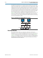
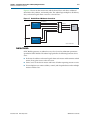
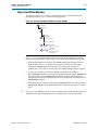
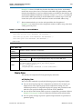
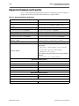
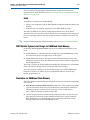
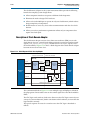
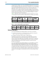
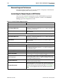
11–10
Chapter 11: Avalon Memory-Mapped Bridges
Avalon-MM Pipeline Bridge
Functional Description
Figure 11–8 shows a block diagram of the Avalon-MM pipeline bridge component.
Figure 11–8. Avalon-MM Pipeline Bridge Block Diagram
Avalon-MM Pipeline Bridge
Master-to-Slave
Pipeline
D
Master-to-Slave
Signals
D
Q
ENA
Master
I/F
Slave
I/F
Connects to an
Avalon-MM
Slave
Interface
Master-to-Slave
Signals
Q
waitrequest
Pipeline
Wait Request
Logic
waitrequest
Slave-to-Master
Signals
waitrequest
Q
D
Connects to an
Avalon-MM
Master
Interface
Slave-to-Master
Signals
Slave-to-Master
Pipeline
The following sections describe the component’s hardware functionality.
Interfaces
The bridge interface is composed of an Avalon-MM slave and an Avalon-MM master.
The data width of the ports is configurable, which can affect how SOPC Builder
generates dynamic bus sizing logic in the system interconnect fabric. Both ports
support Avalon-MM pipelined transfers with variable latency. Both ports optionally
support bursts of lengths that you can configure.
Pipeline Stages and Effects on Latency
The bridge provides three optional register stages to pipeline the following groups of
signals.
■
SOPC Builder User Guide
Master-to-slave signals, including:
■
address
■
writedata
■
write
■
read
■
byteenable
■
chipselect
■
burstcount (optional)
December 2010 Altera Corporation