1
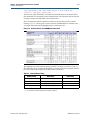
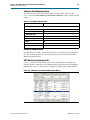
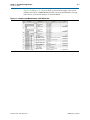
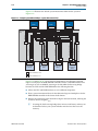
Chapter 6: Component Editor
Signals Tab
6–3
You can also use the component editor to define the interface to components outside
the SOPC Builder system. In this case, you do not provide HDL files. Instead, you use
the component editor to interactively define the hardware interface.
After you specify an HDL file, the component editor analyzes the file by invoking the
Quartus II Analysis and Elaboration module. The component editor analyzes signals
and parameters declared for all modules in the top-level file. If the file is successfully
analyzed, the component editor’s Signals tab lists all design modules in the Top
Level Module list. If your HDL contains more than one module, you must select the
appropriate top-level module from the Top Level Module list.
All files are managed in a single table, with options for Synth and Sim. You can select
the Top option to select the top-level file for synthesis. When the top-level module is
changed, the component editor performs best-effort signal matching against the
existing port definitions. If a port is absent from the module, it is removed from the
port list. You can use the up and down arrows to specify the HDL file analysis order.
By default, all files are added with both Synth and Sim options turned on. To add a
simulation-only file, turn off the Synth option for that file. Files that turn on the Sim
option are passed to ModelSim® for simulation. To add a synthesis-only file, turn off
the Sim file option. Only files that you mark for Synth are added to the Quartus II IP
File (.qip) for your project.
c The component editor determines the signals on the component when only the
top-level module or entity is added to the table, but all of the files required for the
component must be added for the component to compile in Quartus II software or
work in simulation.
Top-Down Design
The Create HDL Template button on the HDL Files tab allows you to create an HDL
template for a component if you have not provided a HDL description for it. Clicking
the Create HDL Template button shows you the component HDL and lets you choose
between Verilog HDL and VHDL. Altera recommends that you define your signals,
interfaces, parameters and basic component information, including the component
name, before creating the HDL template by clicking Save. The component editor
writes <component_name>.v or <component_name>.vhd to your project directory.
After you have component the component’s HDL code, you can add other files that
are required to define your component, including the _hw.tcl file, and synthesis and
simulation files using the Add button on the HDL Files tab.
Signals Tab
You use the Signals tab to specify the purpose of each signal on the top-level
component module. If you specified a file on the HDL Files tab, the signals on the
top-level module appear on the Signals tab.
The Interface list also allows creation of a new interface so that you can assign a signal
to a different interface without first switching to the Interfaces tab. Each signal must
belong to an interface and be assigned a legal signal type for that interface. In addition
to Avalon Memory-Mapped and Streaming interfaces, components typically have
clock interfaces, interrupt interfaces, and perhaps a conduit interface for exported
signals.
December 2010
Altera Corporation
SOPC Builder User Guide