1
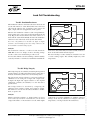
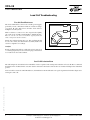
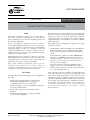
Test #1 Zero Balance Test #2 Insulation Resistance OK VPG-08 OK Te Br Inte VPG Transducers Wrong Wrong Load Cell Troubleshooting TEST PROCEDURES AND ANALYSIS Mechanical Moisture or chemical overload Test Procedures andfor Analysis The diagram below represents a proposed sequence testing load cells after a particular system ingress thea proposed fault location byfor moving relatively deadweight over each load cell, The malfunction. diagram below Isolate represents sequence testing a load cells aftersmall a particular system malfunction. Isolate the faultor location by moving a relatively small by disconnecting load cell by deadweight load cell. over each load cell, or by disconnecting load cell by load cell. R1kΣ Sudden change in Zero point Unstable readings, random change in Zero point Scale reads overload, incorrect or not at all Erratic readings when load is appliedcircuit or removed Short Brok or com to housing / screen Test #1 Zero Balance Test #2 Insulation Resistance OK OK Test #3 Bridge Integrity OK TEST #1: ZERO BALANCE Wrong Mechanical overload Test #4 Shock Resistance Electrica or in shor OK Wrong Wrong The Zero Balance is defined as the load Wrong cell output in a "no-lo deadload) has to beElectrical removed from the load cell. Low capacity load c Moisture overload Failed electrical or chemical or internal connection the ingress load cell is designed to measure force to prevent the weight of the short circuit The load cell should be connected to a stable power supply, preferab R≤1 kΩ R∞ R1kΣ R4 of at least 10 volts. Disconnect any other load cell for multiple load c Measure across Short circuit the voltage Broken wire the load cell's output leads with a milli to housing / screen or component excitation voltage to obtain the Zero Balance in mV/V. Compare the certificate ( if available ) or to the data sheet. Test #1: Zero Balance TEST #1: ZERO BALANCE A PPL I CAT I O N N OT E The Zero Balance is defined as the load cell output in Input The Zero BalanceTherefore, is defined all as weight the load(including cell output in a "no-load" situation. Therefore, all weight (including a "no-load" situation. deadload) has has to be removed from Lowcapacity load cells should be measured in the position in which deadload) to be removed fromthe theload load cell. Low ~ capacity cellsisshould be to measured thetoposition the load cell designed measure in force preventin the weight of the element giving wrong results. whichThe the load load cell cell should is designed to measure topower prevent be connected to aforce stable supply, preferably a load cell indicator with an excitation voltage the weight of the element giving wrong results. of at least 10 volts. Disconnect any other load cell for multiple load cell systems. Measure the voltage across the cell's output leads with a millivoltmeter and divide this value by the input or The load cell should be connected to aload stable power supply, excitation voltage to obtainwith the Zero Balance involtage mV/V. Compare the Zero balance to the original load cell calibration preferably a load cell indicator an excitation ( if available ) or toany the other data sheet. of at certificate least 10 volts. Disconnect load cell for Output multiple load cell systems. V Measure the voltage across the load cell's output leads Input with a millivoltmeter and divide this value by the input ~ or excitation voltage to obtain the Zero Balance in mV/V. Compare the Zero balance to the original load cell calibration certificate ( if available ) orANALYSIS to the data sheet. zero output changes per time period are most likely in the strain gauge resistance Changes in Zero undergoing Balancea change usually occur if the loadbecause cell has been Analysis Output of chemical or moisture intrusion. However, in this case excessive shocks.theLoad cells that experience progressive zero ou insulation resistance and/or the bridge integrity will Changes in Zero Balance usually occur if the load cell also be has been permanently deformed by overloading and/or undergoing a change incompromised. the strain gauge resistance because of chem excessive shocks. Load cells that experience progressive the insulation resistance and/or the bridge integrity will also be comp ANALYSIS V Changes in Zero Balance usually occur if the load cell has been permanently deformed by overloading and/or For technical support, contact in Americas www.vpgtransducers.com Document Number: 11867 excessive shocks. Load cells that experience progressive zero [email protected], output changes per time period are most likely in Europe [email protected], in China [email protected], 2 Revision undergoing a change in the strain gauge resistance because of chemical or moisture intrusion. However, in14-Dec-2011 this case in Taiwan [email protected] the insulation resistance and/or the bridge integrity will also be compromised.