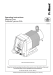
1
®
Operating Instructions
Metering Pump
ProMinent® gamma G/4b
Affix type identification plate here!
Please first read the operating instructions from cover to cover! • Do not throw them away!
The warranty does not cover damages due to faulty operation!
Part No. 981071
ProMinent Dosiertechnik GmbH • D-69123 Heidelberg • Germany
BA G4 015 8/99 GB
Device Overview/Control Elements
1 2 3 4
5 6 7 8
gamma/4
50
60
40
30
70
80
20
90
10
100
P
STOP
STOP
START
START
13 12 11 10 9
14
16
17 / 17a / 17b
15
gam
ma
/4
70
60 5
0
80
40
30
90
10
0
20
10
P
SSTT
OO
P
SST P
TA
ARRT
T
22
21 20 19 18
G/4b-002-D
Always unfold the page first!
➠
More detailed information
on pages:
1
Pulse/pilot light (yellow) ................................................................ 51, 75, 81
2
Down key .............................................................................................. 51 ff.
3
Stroke length adjustment knob .................................................................. –
4
LCD display field ....................................................................................... 50
5
Program selection key .......................................................................... 51 ff.
6
Up key.................................................................................................. 51 ff.
7
Stop/start key....................................................................................... 51 ff.
8
Display light for empty display and fault annunciation (red) .......... 51, 56, 76
9
Connection thread PG-9 for relay output (with blank plug) ...................... 51
10
Connection socket metering monitor ..................................... 34, 37, 51, 59
11
Connection socket for float switch (with function plug) .... 34, 37, 51, 54, 59
12
On/off control (with function plug) ..................................... 34, 37, 54, 58, 59
13
Mains supply............................................................................................ 34
14
View window .............................................................................................. –
15
Enclosure................................................................................................... –
16
Pressure valve .............................................................................. 25, 29-33
19
Liquid end ........................................................................................... 76-80
20
Intermediate disk with leakage bore ................................................... 76-80
21
Suction valve ................................................................................ 25, 29-33
22
Short operating instructions ....................................................................... –
Only for PP and NP version:
17
Bleed valve ................................................................................................ –
17 a
Fine bleed valve ......................................................................................... –
17 b
Star handle ................................................................................................ –
18
Bypass tube nozzle ................................................................................... –
Page 2 of 88 pages
Version 2.0
Imprint:
Operating Instructions gamma 4b metering Pump
© ProMinent Dosiertechnik GmbH, 1993
ProMinent Dosiertechnik GmbH
Im Schuhmachergewann 5-11
D-69123 Heidelberg, Germany
P.O. Box 101760
D-69007 Heidelberg, Germany
[email protected]
www.prominent.de
Subject to alterations
Techn. documentation:
Bartha Docuteam
D-64625 Bensheim
Issue 08/99, version 2.0
Printed in Germany
Version 2.0
Page 3 of 88 pages
Contents
Page
i
General notes for users .......................................................... 7
1
Introduction ............................................................................... 8
2
Functions .................................................................................. 8
3
2.1
Functional principle .......................................................... 8
2.2
Functions ......................................................................... 9
2.2.1 The mechanics ..................................................... 9
2.2.2 The setting range ................................................ 10
2.2.3 Options ............................................................... 11
Technical data ......................................................................... 13
3.1
3.2
Technical data G/4b (with 120 strokes/min) ................... 13
Technical data G/4b (with 180 strokes/min) ................... 14
4
Installation dimensions ............................................................ 16
5
Tests for your safety ................................................................ 17
6
Accessories ............................................................................ 19
6.1
6.2
6.3
6.4
6.5
6.6
6.7
6.8
6.9
6.10
6.11
6.12
6.13
Float switch ................................................................... 19
Control cables ............................................................... 19
Foot valves ................................................................... 19
Injection valves ............................................................. 19
Injection lances ............................................................. 19
Back-pressure valves .................................................... 19
Accumulators ................................................................ 19
Metering monitors ......................................................... 19
Suction lances .............................................................. 19
Supply tanks ................................................................. 19
Manual/electric stirrers .................................................. 19
Console ........................................................................ 19
ProMinent "Remote Control".......................................... 19
7
SAFETY INSTRUCTIONS ...................................................... 20
8
Device identification/identity code ............................................ 21
9
Unpacking ............................................................................... 22
10 Installation ............................................................................... 24
10.1 Installing the pump: mechanical part ............................... 24
10.1.1 Pump installation with console or tank ............... 24
10.1.2 Connection of suction/discharge line to the pump .. 24
10.1.3 Installation suction line (general instructions) ..... 26
10.1.4 Installation discharge line (general information) ...... 27
10.1.5 Installation bybass bleed line ............................. 27
Page 4 of 88 pages
Version 2.0
Contents
Page
10.1.6 Installation examples ......................................... 28
Correct installation: ........................................... 29
Incorrect installation: ........................................ 33
10.2 Installation pump: electrical part...................................... 34
10.2.1 Electrical connection (general instructions) ....... 34
10.2.2 Operating modes ............................................. 35
10.2.3. Functions superior to the operating modes ....... 35
10.2.4 Parallel connection ........................................... 36
10.2.5 Wiring diagram ................................................. 37
11 Commissioning ....................................................................... 38
11.1
11.2
11.3
11.4
11.5
General instructions ..................................................... 38
Operating conditions .................................................... 38
Suction capacity/bleeding ............................................. 39
Metering accuracy ........................................................ 40
Determining the capacity by means of nomograms ....... 41
11.5.1 General information ......................................... 41
11.5.2 Nomogram 1000/1001 .................................... 43
11.5.3 Nomogram 1601/1602 .................................... 44
11.5.4 Nomogram 1201/1203 .................................... 45
11.5.5 Nomogram 0803/0806 .................................... 46
11.5.6 Nomogram 1002/1003 .................................... 47
11.5.7 Nomogram 0308/0313 .................................... 48
11.5.8 Nomogram 0215/0223 .................................... 49
12 Operation ................................................................................ 50
12.1 Explanation of the operating and display elements ......... 50
12.1.1 Display ............................................................. 50
12.1.2 Control panel: keys and display lamps .............. 51
12.1.3 Multiple connector strip. Symbols and connections 51
12.2 Overview operating diagram ........................................... 52
12.3 Operating functions basic version ................................... 53
12.3.1 Starting the pump ............................................. 53
12.3.2 Stopping the metering ...................................... 53
12.3.3 Internal "Manual" operation .............................. 54
12.3.4 External "Contact" operation ............................. 55
12.3.5 Connecting a float switch .................................. 56
12.3.6 On/off function "Pause" .................................... 58
12.3.7 Metering monitor "flow"..................................... 58
12.3.8 Error messages acknowledging error messages ........................ 59
Version 2.0
Page 5 of 88 pages
Contents
Page
12.4 Overview operating scheme (option version) .................. 60
12.5 Operation (option version) .............................................. 62
12.5.1 Analog control .................................................... 62
12.5.2 Pulse control ...................................................... 66
12.5.3 Preselection operation and memory ................... 71
12.5.4 Relay option ....................................................... 72
Switching mode no. 1:
"Fault annunciation relay de-energising" ............. 72
Switching mode no. 2:
"Pacing relay energising".................................... 72
Switching mode no. 3:
"Fault annunciation relay energising" .................. 72
Switching mode no. 4:
"Timer relay energising" ..................................... 72
13 Maintenance ........................................................................... 74
14 Trouble shooting/eliminating errors .......................................... 74
14.1 Errors you can eliminate yourself .................................... 74
14.1.1 Pump does not prime in spite of full stroke
movement and bleeding ..................................... 75
14.1.2 Float switch does not switch the metering
pump off at minimum chemical level ................... 75
14.1.3 Pump does not meter although yellow display
lamp (1) flashes ................................................. 75
14.1.4 Red warning lamp (8)lights up - "Error"
readout on display (4) flashes ............................. 76
14.1.5 Fluid is leaking at the intermediate disk............... 77
14.1.6 Exchanging the complete liquid end ................... 80
14.2 Errors which require customer service assistance ........... 80
14.2.1 Pump does not move,
yellow display light (1) does not light up,
no readout on the display (4) .............................. 81
14.2.2 Mains connection line (system cable) damaged .. 81
15 Repair ..................................................................................... 82
16 Disposal of old parts ............................................................. 83
Appendix/cross section of pump ................................................. 84
Warranty application .................................................................... 85
Safety certificate ........................................................................... 87
Page 6 of 88 pages
Version 2.0
General Notes for Users
i
General notes for users
These operating instructions describe the technical data and functioning
of the G/4b metering pump, provide comprehensive safety instructions
and are arranged in clear operational steps, as explained in the
following examples.
Equipment descriptions are indicated by normal text:
Analogue signals such as current signals 0/4 - 20 mA or voltage signals
adjustable from 0 - 60 mV, 0 - 1 V and 0 - 10 V can be used for direct
proportional control of the stroking rate.
Operations/activities to be performed are shown by bullets:
• Press in dowel and screw in the screw so far until the screw head still
projects 3.5 to 4 mm.
References are shown by arrows and bold texts:
> Detailed description from page 61
Safety precautions are indented, in bold italics and provided with a
warning symbol:
WARNING:
The metering pump can still contain water from the factory
test!
Work instructions are indented and set in italics:
PLEASE NOTE:
You obtain a fixed hose connection if you pull shortly on the line
connected to the liquid end and subsequently retighten the union
nut hand-tight!
Mains supply
Version 2.0
Key words to enable the relevant part of the text to be quickly located are
given in italics and arranged to the left of the text.
Page 7 of 88 pages
Introduction/Functions
1
Introduction
ProMinent® gamma/4b are microprocessor-controlled, solenoid-driven
diaphragm metering pumps capable of dialogue for metering fluids.
Sophisticated mechanics, state-of-the art control technology, easy uniform operation with user guidance in plain language, maximum operational
safety thanks to diagnosis of external error sources too, almost unlimited
adaption possibilities to process automation systems, self-monitoring of
the metering capacity and high metering safety in the capacity range of
0,2 to 23 l/h at a maximum counter pressure of 16 to 1,5 bar.
2
Functions
2.1
Functional principle
Gamma/4b metering pumps predominantly consist of
a pump drive
with enclosure, stroke solenoid and electronic microprocessor control
and a liquid end
with liquid end, suction and pressure connection, pump diaphragm and
intermediate disk.
The feeding procedure takes place in batches. The stroke length is max.
1.25 mm.
For every pulse which comes from the electronics a magnetic field builds
up in the field coil and a moveable mounted pressure piece is attracted.
In doing so the pump diaphragm displaces the medium in the liquid end
by means of a pressure valve, and the valve on the suction side closes.
After the switch-on pulse is terminated the magnetic field de-energises,
the pressure piece from the stroke solenoid is reset by the recuperating
spring and the diaphragm returns to the initial position. The pressure side
is closed. In this way the medium is sucked into the liquid end (suction
stroke).
The capacity per stroke can be preselected via the stroke length adjustment
knob (3).
The metering pumps can be retrofitted to suit the customer’s specific
needs (options).
Page 8 of 88 pages
Version 2.0
Functions
2.2
Functions
2.2.1
The mechanics
The enclosure
Highest protection against chemical attacks, dust and spray water by
means of glass-fibre reinforced plastic. Sturdy, impact-proof, light and
enclosure rating IP 65 according to DIN 40050 and IEC 529.
The solenoid drive
Conventional pump drives consist of an electric motor with gears and
many moving parts.
The ProMinent solenoid drive has only one moving part, the armature!
This is a low-maintenance short-stroke solenoid with a new type of
noise suppression and a maximum stroke length of 1.25 mm.
The stroke length adjusting mechanism is connected directly to the
solenoid. Thus a most accurate stroke length adjustment is possible
without locking and self- adjustment.
The pump diaphragm
A DEVELOPAN® composite pump diaphragm with long service life of
fabric-reinforced high-quality EPDM with a vulcanised steel core and
PTFE Teflon coating on the media-contacted side.
The liquid end
Liquid ends for gamma pumps are available in four material versions
- polypropylene (PP)
- acrylic (NP)
- PTFE (TT)
- stainless steel 1.4571 (SS)
Additionally material versions PP and NP have a combined bleed valve
with fine adjustment.
Especially for highly viscous materials, liquid ends from the HV series
are available in
- polypropylene (PP4)
with extended flow cross section and larger, springloaded single ball
valves.
Version 2.0
Operating voltages
Gamma metering pumps are available for 230 and 115 V mains
voltages. Wide voltage ranges are accepted: from 207 to 254 V in the
upper and from 108 to 135 V in the lower range: for mains frequencies
from 50 to 60 Hz.
Self-monitoring
The electronic control system is continuously self-monitoring. In the
event of a system error in the microprocessor, the pump is switched off
and an alarm is issued.
Lighting
The optional illumination of the LCD display (4) guarantees that the
display can be easily read even in bad light conditions.
Page 9 of 88 pages
Functions
2.2.2
"Pause" control
The setting range
By means of the universal control cable the pump can be switched on and
off voltage-free. The control function operates according to the zero signal
current: when the contact is open the pump is idle, brown and black wires
are not connected with each other. When the contact is closed the pump
operates, brown and black wires are connected with each other.
The pause control is effective in each of the functions described here
below.
> Detailed description from page 58
Internal operation "Manual"
The setting of the stroke volume takes place using the stroke length (3).
This can be set from 0 - 100% up to a maximum of 1.25 mm. Accurate
metering is achieved from 30% stroke length.
The stroking rate can be set with the keys (2 or 6) from 120 (180)
to 0 strokes/min. The number is displayed on the display (4).
> Detailed description from page 54 onwards.
External operation "Contact"
The stroke cycle of the gamma pump can also be controlled externally e.g.
via a water meter contact. The connection takes place with a control cable
at the connection socket (12). Each incoming pulse corresponds to one
metering stroke. A max. of 120 (180) strokes/min are possible - there is no
danger of overdriving.
Please note:
The stroking rate set in the internal operation "Manual" is valid for
the external operation "Contact" as max. stroking rate.
> Detailed description from page 55
Metering monitoring "flow"
Gamma metering pumps check their own performance. After the assembly
of an optional metering monitor on the liquid end (19) and activation,
every complete metering stroke is recorded and passed on to the pump
electronics. If the correct metering amount is not present eight times the
pump stops.
> Detailed description from page 58
Float switch
By attaching the two-stage float switch to the socket (11) the supply of fluid
media is monitored. When a minimum height is reached an early warning
is issued, the pump however continues to operate.
The pump switches off only once the level has dropped another 30 mm.
A fault annunciation relay can be switched as an option.
> Detailed description from page 58
Page 10 of 88 pages
Version 2.0
Functions
2.2.3
Options
The versions listed below can be obtained from ProMinent individually
or as a freely combinable package.
Analog Control
Analogue signals can be used for proportional control of the stroking
rate. The stroking rate is varied between 0 and 100% according to the
0/4 - 20 mA signal.
For example, in the event of a cable rupture (input signal < 4 mA) an
alarm message is issued and the pump switches off. Other input
signals (0-1 V, 0-10 V, 0-60 mV) can be entered on ordering with the
identity code.
> Detailed description from page 62
Pulse Control
Pulse Control is used for adapting the gamma metering pump to all
types of pacers and for saving additional control devices.
The following functions listed below can be set using the keyboard:
Pulse set-down
and step-up
By entering a factor in the range from 0.01 to 9999 the step-down or
step-up ratio can be set.
Example:
Step-down withfactor 0.01
Step-down withfactor 0.25
Step-down with factor 1
Step-up with
factor 4
Step-up with factor 9999
: 100
: 4
: 1
: 1
: 1
pulses =
pulses =
pulse =
pulse =
pulse =
1
1
1
4
9999
metering stroke
metering stroke
metering stroke
metering strokes
metering strokes
> Detailed description from page 67
Display "f"
Displays the stroking rate in 0 to 120 (180) strokes/min.
> Detailed description from page 69
Predetermining counter "N÷ "
The predetermined number of strokes can be called up by means of a
voltage-free contact or the P key (5). The strokes still to be executed
are shown on the display (4) subtracting.
> Detailed description from page 69
Stroke counter "N"
The stroke counter in all operating modes counts the strokes executed
and shows these on the display (4). A maximum of 9999 strokes can
be counted, after this the display starts at 1 again.
> Detailed description from page 69
Memory "Mem"
A memory with a storage capacity of 65,535 (216-1) pulses or strokes
can be additionally switched on. Thus incoming pulses can be registered
and worked off.
> Detailed description from page 71
Version 2.0
Page 11 of 88 pages
Functions
Relay output (9)
This is used for remote transfer of alarm messages or as a pacer for
remote control e.g. of a second ProMinent® metering pump in synchronous
pacing operation.
The relay output can be used for:
Collective fault indication
For the level early warning and final switch off, metering monitor, system
error annunciation, fuse and mains failure annunciation. Function: relay
de-energises in the event of an alarm.
Alarm relay
For the level early warning and final switch off, metering monitor and
system error message. Function: relay energises in the event of an alarm.
Pacing relay
With contact pacing parallel to the discharge stroke of the metering
solenoid. Contact duration 150 ms.
Timer relay
Switches parallel to 31 different metering times (from 1 minute to up to 24
hours), repeating daily or weekly.
> Detailed description from page 72
Page 12 of 88 pages
Version 2.0
Technical Data
3
Technical Data
3.1
Technical Data G/4b (with 120 strokes/min)
Gamma /4b, Typ
1000
1601
1201
0803
1002
Capacity (l/h)
Capacity (ml/stroke)
at max. counter pressure (bar)
0.2
0.027
10
1,0
0.14
16
1.7
0.24
12
3.4
0.48
8
Capacity (l/h)
Capacity (ml/stroke)
at med. counter pressure (bar)
0.27
0.038
5
1.2
0.17
8
1.9
0.27
6
Suction lift (m WS)
1.5
6
Priming lift
at 100% stroke length (m) **
0.5
Max. pressure suction side(bar)
0308
0215
2.3
0.32
10
1002
HV
1.7
0.24
10
8.4
1.17
3
14.8
2.05
1.5
3.8
0.53
4
2.6
0.36
5
2.5
0.34
5
9.1
1.27
1.5
15.8
2.20
1
6
3
6
6
6
1.5
1.8
2.5
2.8
1.0
-
1.8
1.5
8.0
8.0
5.5
3.0
3.0
3.0
1.5
0.8
Max. stroking rate (stroke/min)
120
120
120
120
120
120
120
120
Liqid end version ***
with suction and
discharge connections ***
PP
NP
TT
SS
PP
NP
TT
SS
PP
NP
TT
SS
PP
NP
TT
SS
PP
NP
TT
SS
PP
-
PP
NP
TT
SS
PP
NP
TT
SS
Connection size
o.Ø x i.Ø (mm)
6x4
6x4
6x4
6x4
8x5
DN10
8x5
12x9
Shipping weight. PP. NP. TT (kg)
2.7
2.7
2.7
2.7
2.9
2.9
2.9
3.1
Shipping weight. SS (kg)
3.4
3.4
3.4
3.4
4.1
4.1
4.1
4.7
Medium power drain
at max. 120 strokes/min (W)
refer to typelabel
Peak power drain
at discharge stroke (A)
refer to typelabel
**) Priming lifts with clean dampened valves for water and suction
**) line as specified.
Liquid end version
Liquid end
Suction/discharge valve
seals
valve balls
PP1
PP2
PP3
PP41)
NP1
NP2
NP3
TT1
SS…
polypropylene
polypropylene
polypropylene
polypropylene
acrylic
acrylic
acrylic
PTFE with carbon
stainless steel2)
polypropylene
polypropylene
polypropylene
polypropylene
PVC
PVC
PVC
PTFE with carbon
stainless steel2)
EPDM
FPM (Viton® A)
FPM (Viton® B)
EPDM
FPM (Viton® A)
EPDM
FPM (Viton® B)
PTFE
PTFE
ceramic
ceramic
ceramic
ceramic
ceramic
ceramic
ceramic
ceramic
ceramic
1)
PP4 with Hast. C valve springs, 2) material no. 1.4571
DEVELOPAN® = pump diaphragm with PTFE layer.
Viton® (FPM) is a registered trademark of DuPont Dow Elastomers.
Version 2.0
Page 13 of 88 pages
Technical Data
3.2
Technical Data G/4b (with 180 strokes/min)
Gamma /4b, Typ
1001
1602
1203
0806
1003
Capacity (l/h)
Capacity (ml/stroke)
at max. counter pressure (bar)
0.3
0.027
10
1.5
0.14
16
2.5
0.24
12
5.3
0.48
8
Capacity (l/h)
Capacity (ml/stroke)
at med. counter pressure (bar)
0.42
0.038
5
1.8
0.17
8
2.9
0.27
6
Suction lift (m WS)
1.5
6
Priming lift
atz100% stroke length (m) **
0.5
Max. pressure suction side(bar)
0313
0223
3.4
0.31
10
1003
HV
3.0
0.28
10
13.0
1.20
3
23.0
2.13
1.5
5.6
0.53
4
3.7
0.34
5
3.7
0.34
5
15.5
1.43
1.5
25.5
2.36
1
6
3
6
6
6
1.5
1.8
2.5
2.8
1.0
-
1.8
1.5
8.0
8.0
5.5
3.0
3.0
3.0
1.5
0.8
Max. stroking rate (stroke/min)
180
180
180
180
180
180
180
180
Liqid end version ***
with suction and
discharge connections ***
PP
NP
TT
SS
PP
NP
TT
SS
PP
NP
TT
SS
PP
NP
TT
SS
PP
NP
TT
SS
PP
-
PP
NP
TT
SS
PP
NP
TT
SS
Connection size
o.Ø x i.Ø (mm)
6x4
6x4
6x4
6x4
8x5
DN10
8x5
12x9
Shipping weight. PP. NP. TT (kg)
2.7
2.7
2.7
2.7
2.9
2.9
2.9
3.1
Shipping weight. SS (kg)
3.4
3.4
3.4
3.4
4.1
4.1
4.1
4.7
Medium power drain
at max. 120 strokes/min (W)
refer to typelabel
Peak power drain
at discharge stroke (A)
refer to typelabel
**) Priming lifts with clean dampened valves for water and suction
**) line as specified.
Liquid end version
Liquid end
Suction/discharge valve
seals
valve balls
PP1
PP2
PP3
PP41)
NP1
NP2
NP3
TT1
SS…
polypropylene
polypropylene
polypropylene
polypropylene
acrylic
acrylic
acrylic
PTFE with carbon
stainless steel2)
polypropylene
polypropylene
polypropylene
polypropylene
PVC
PVC
PVC
PTFE with carbon
stainless steel2)
EPDM
FPM (Viton® A)
FPM (Viton® B)
EPDM
FPM (Viton® A)
EPDM
FPM (Viton® B)
PTFE
PTFE
ceramic
ceramic
ceramic
ceramic
ceramic
ceramic
ceramic
ceramic
ceramic
1)
PP4 with Hast. C valve springs, 2) material no. 1.4571
DEVELOPAN® = pump diaphragm with PTFE layer.
Viton® (FPM) is a registered trademark of DuPont Dow Elastomers.
Metering deviances
Page 14 of 88 pages
For all material versions –5% to +15%
Version 2.0
Technical Data
Reproducibility of the metering
Permissible ambient temperature
Resolution of the stroke setting
When used according to the instructions of the operating instructions
± 2%
-10 °C to +45 °C
1:20
Power supply
230 V ± 10%; 115 V ± 10%, 50/60 Hz
Voltage range
207 to 254 V: 108 to 135 V
Enclosure rating
IP 65
Insulation class
F
Control function
- Voltage level with
open contact
: approx. +5 V
- Impedance
: 10 kOhm
- Control
: With voltage-free contact or semiconductor control with a residual
voltage of < 700 mV, the contact load
is approx. 0.5 mA at +5 V.
Contact input
- Voltage level with
open contact
: approx. +5 V
- Impedance
: 10 kOhm
- Control
: With voltage-free contact or semiconductor control with a residual
voltage of < 700 mV, the contact load
is approx. 0.5 mA at +5 V.
- Max. pulse freq.
: 40 pulses/sec
- Necessary contact duration : 20 ms
Option Analog - current
- Burden
: approx. 70 ohm
- max. input current
: 50 mA
Relay option
Fault indicating relay
max. load:
250 V – 2 A, floating
Pacing relay – max. load:
42 V – 0,1 A, floating
Version 2.0
Page 15 of 88 pages
Installation Dimensions
4
Installation dimensions
Version
for PP4 = DN 10
gamma/4b
A
B
C
D
E
F
G
1000, 1001, 1601, 1602, 1201, 1203 PP
NP
TT
SS1
SK1
232
230
213
211
211
186
179
173
164
162
17
19
25
34
36
70
70
60
60
60
6x4
6x4
6x4
6x5
1/8"
81
81
79
79
79
38
38
38
38
38
0803, 0806
PP
NP
TT
SS1
232
230
213
211
186
179
178
169
17
19
20
29
70
70
70
70
6x4
6x4
6x4
6x5
81
81
79
79
38
38
38
38
1002, 1003
PP
NP
TT
SS1
225
230
216
214
186
179
206
206
17
19
-8
-8
70
70
80
80
8x5
8x5
8x5
8x7
76
81
79
77
50
50
50
50
0308, 0313
PP
NP
TT
SS1
225
223
216
214
186
187
206
206
17
11
-8
-8
70
85
80
80
8x5
8x5
8x5
8x7
75
75
79
77
50
50
50
50
0215, 0223
PP
NP
TT
SS1
225
223
216
214
197
195
214
209
6
3
-16
-11
90
100
95
95
12x9
12x9
12x9
12x10
76
76
79
77
66
66
66
66
1002 HV, 1003 HV
PP4
214
172
-4
70
DN10
60
50
Page 16 of 88 pages
Version 2.0
Tests
5
Test for your safety
The gamma pump series is supplied with the CE symbol. This certifies that
it complies with relevant EC regulations which are specified in the conformity
declaration.
BG Chemie
Version 2.0
(Employers insurance ass.) Test according to ZH 1/109 (closed refilling
and metering systems - basic rules for the acceptance) passed in
connection with the appropriate liquid end version.
Page 17 of 88 pages
Conformity Declaration
EC Declaration of Conformity
We,
ProMinent Dosiertechnik GmbH
Im Schuhmachergewann 5 - 11
D - 69123 Heidelberg
hereby declare that, on the basis of its functional concept and design and in the version brought into circulation by us, the product specified in the following complies with the relevant, fundamental safety and health
stipulations laid down by EC directives.
Any modification to the product not approved by us will invalidate this declaration.
Product description:
Metering pump, Series Gamma/ _b
Product Type:
G/4b… , G/5b…
Serial number:
See type identification plate overleaf and on device
Relevant EC
regulations:
EC - machine regulation (89/392/EEC)
subsequently 93/44/EEC
EC - low voltage regulation (73/23/EEC)
EC - EMC - regulation 89/336/EEC
subsequently 92/31/EEC
Harmonised standards used,
in particular:
EN 292-1 , EN 292-2 , EN 809
EN 60335-1 A6 , EN 60335-2-41
EN 50081-1/2 , EN 50082-1/2 , EN 55014
EN 60555-2 , EN 60555-3
National standards and
technical specifications
used, in particular:
DIN VDE 0700 T1 , DIN VDE 0700 T41 , DIN VDE 0700 T500
CSA Standard C 22.2 No. 0 - M 91 (115 V-Version)
CSA Standard C 22.2 No. 108 - M 89 (115 V-Version)
Date/manufacturer's signature:
28.03.1996
.......................................................................
The undersigned:
Mr. Manfred Hüholt, factury manager
Page 18 of 88 pages
Version 2.0
Accessories
6
Accessories
WARNING
ProMinent® metering pumps may not be assembled with
foreign parts which have not been tested and recommended
by ProMinent. Failure to observe this may result in personal
injury and damage to property for which no liability is
accepted!
6.1
Order no. 14.20.93.4
Two-stage with 2 m connection cable
6.2
Order no. 70.77.18.3
Order no. 70.77.02.7
Float switch
Control cables
4-wire, 2 m, universal control cable
2-wire, 2 m, remote contact cable
6.3
Foot valves
With suction filter and ball check valve for connection at the end of the
suction line.
6.4
Injection valves
With spring-loaded ball check valve for metering into open or closed systems
and for fastening the discharge line; assembly direct to the liquid end.
6.5
Injection lances
For metering into large pipe cross sections and for preventing blockages
for media which effloresce.
6.6
Back-pressure valves
For accurate metering at low counter pressure or as relief safety valve.
6.7
Accumulators
For pulsation dampening e.g. for long discharge lines.
6.8
Metering monitors
For monitoring the metering. After eight non acknowledged metering strokes
an error message is displayed and the metering pump is switched off.
6.9
Suction lances
With foot valve and float switch for disposable drums or supply tanks.
6.10
Supply tanks
From 35 to 1000 l content with lockable screw cap and necessary
accessories.
6.11
Manual/electric stirrers
For mixing and preparing metering solutions.
6.12
Console
For stable mounting of the pump.
6.13
ProMinent ® "Remote Control"
Type G4Ra consisting of gamma/4 metering pump and remote control
part. With this the metering pump can be controlled and operated from up
to 100 m via the remote control part.
Version 2.0
Page 19 of 88 pages
SAFETY INSTRUCTIONS
7
SAFETY INSTRUCTIONS
WARNING:
Pumps must be accessible at all times for operation and
service. Accesses may not be closed off or blocked!
WARNING:
If hazardous or unknown metering media are used, always
first empty out the liquid end and rinse it out for maintenance
and repair work! Observe the safety data sheets of the
metering fluids!
WARNING:
When metering dangerous or unknown fluids, protective
clothing must be worn when working on the liquid end
(glasses, gloves)!
WARNING:
When operating the metering pump against a closed shutoff element on the delivery side, the resulting pressure
build-up can reach a multiple of the maximum permissible
backpressure!
This can cause the delivery line to burst!
To avoid this, it is advisable to install a ProMinent
multifunction valve which limits the maximum pressure
which can be reached!
WARNING:
The maximum operating pressure for PTFE lines N 1/8"
plug-in system on pipe nipple for gamma/4b SK pumps is
6 bar!
WARNING:
Applicable national and international regulations (ExVo,
VbF, DIN VDE 0165) must be observed when metering
combustible media!
ATTENTION
Only set the stroke length when the pump is running when the
setting bolt of the metering stroke is briefly relieved!
PLEASE NOTE:
Only use the gripper rings and hose nozzles specified for the
respective hose diameter as well as original hoses with specified
hose dimensions and wall thickness as otherwise the stability
of the connection is not guaranteed!
Avoid reducing the hose sizes!
For long lines and highly viscous media the next highest line
diameter or a pulsation dampener should be used!
Page 20 of 88 pages
Version 2.0
Device identification/identity code
8
Device identification/identity code
The type identification plate affixed on the title page is identical to that on
the supplied pump thus enabling specific allocation between operating
instructions and the pump. Please enter the identity code specified under
"Type" on the type identification plate in the grey entry field below.
G/4b
--- --- --- --- --- --- ---
Series:
G/4b = gamma 4, Version b
Pump size:
1st and 2nd figure
= Backpressure (bar)
3rd and 4th figure
= Capacity (l/h)
120 spm
1000
1601
1201
0803
1002
0308
0215
180 spm
1001
1602
1203
0806
1003
0313
0223
---
---
---
Valve spring:
0 = No spring
1 = With 2 valve springs
1.4571, 0.1 bar
Connection:
0 = Standard as per
technical data
= Special version
……………………
Version
view window:
0 = Standard
1 = With lock
= Special version
……………………
Liquid end material:
PP1 = Polypropylene/EPDM
PP2 = Polypropylene/Viton® A
PP3 = Polypropylene/Viton® B
PP4 = Polypropylene HV/EPDM
NP1 = Acrylic/Viton® A
NP2 = Acrylic/EPDM
NP3 = Acrylic/Viton® B
NS2 = Acrylic/EPDM,
self-degassing
NS3 = Acrylic/Viton®,
self-degassing
PS3 = PVC/Viton®,
self-degassing
TT1 = PTFE with carbon/PTFE
SS1 = Stainless steel 1.4571/
PTFE
SS2 = Stainless steel with
1/4" NPT thread
SK1 = Stainless steel with R1/8"
capillary connection
= Special version
Electrical connection:
Supply cord 2.0 m
A = 230 V ±10 %, 50/60 Hz
Europlug
B = 230 V ±10 %, 50/60 Hz
Swiss plug
C = 230 V ±10 %, 50/60 Hz
Australian plug
D = 115 V ±10 %, 50/60 Hz
USA plug
= Special version
……………………
Control type:
0 = Basictype
1 = Option type
2 = Option type with
LCD lighting
= Special version
--- ---
--- ---
--- ---
Control variant:
0 = Manual + external + pause
1 = As 0 + analog
0…20 mA, 4…20 mA
2 = As 0 + analog
0–60 mV, 0–1 V, 0–10 V
= Special version
……………………
Pulse control:
0 = Without pulse control
1 = With pulse control
= Special version
……………………
Timer/serial interface:
(separate operating instructions)
0 = Without timer
1 = With timer
2 = Terminal RS 232
data cable 2 m
3 = Terminal RS 485
data cable 2 m
4 = Terminal RS 232
data cable 10 m
5 = Terminal RS 485
data cable 10 m
= Special version
……………………
Relay switching mode:
0 = No relay
1 = Fault indicating relay, releasing
2 = Pacing relay, operating
3 = Fault indicating relay, operating
= Special version
……………………
……………………
……………………
Version 2.0
Viton® (FPM) is a registered trademark of DuPont Dow Elastomers.
G/4b-005-GB
Page 21 of 88 pages
Unpacking
9
Unpacking
ATTENTION:
Polystyrene parts are special refuse and may not be mixed with
domestic refuse, and must be disposed of separately (special
refuse collection points)!
Secondary packaging
It is best if you keep secondary packaging complete with the polystyrene
so that you can send the metering pump back in the event of repair or
warranty cases!
Please first compare your delivery note with the contents of the package.
Scope of delivery
- Metering pump with mains cable and plug.
- Connection set for hose/pipe connection in accordance with the
identity code.
- Operating instruction and short instructions - pushed into the base of
the pump.
gam
ma
/4
70
60 5
0
80
40
30
90
10
0
20
10
P
ST
O
SSTT P
A
ARR
TT
Short operating instructions (22)
G/4b-006-GB
Page 22 of 88 pages
Version 2.0
Unpacking
ATTENTION:
Check that the details on the identification plate match the order
details!
If they do not, immediately notify the ProMinent subsidiary or representative
responsible for you (Please see reverse of these operating instructions for
addresses).
G/4b 0215
NP1
ProMinent Dosiertechnik
im Schuhmachergewann
D-69123 Heidelberg
Tel. 06221/8420
Made in Germany
A 93 00…
0
0
0 A 0
TYPE
SER.NR./PN.
POWER SUPPLY
AMP.PULS
DOSING RATE
0
0
0
0
G/4B0215NP1000A00000
is
/ 794067
230 V
50/60Hz
23/25 W
0,9 A
14,8 l/h
1,5 bar
G/4b-007-GB
Each gamma/4 metering pump is provided with an identification plate.
This can be found on the base of the pump.
G/4b-008-D
In addition to the technical basic data the IDENTITY CODE and the serial
no. are specified. Both numbers are to be stated during any enquiry or
when ordering spare parts as they permit a clear identification of the pump
type and material variant.
Please make a note of the following details of the pump delivered so that
these are always available when required:
Version 2.0
Page 23 of 88 pages
Installation
IDENTITY CODE
__________________________________________________
Serial number
__________________________________________________
Place of installation
__________________________________________________
__________________________________________________
Metering application
__________________________________________________
Commissioning
__________________________________________________
10
Installation
10.1
Installing the pump: mechanical part
10.1.1 Pump installation with console or tank
• Assemble metering pump onto a container or a console with screws
and washers (dia. 5 mm).
PLEASE NOTE:
The pump must be fastened in such a way that no vibrations can
arise!
The valves of the liquid end must always be kept upright in order
to guarantee that they function smoothly!
10.1.2 Connection of suction/discharge line to the pump
PLEASE NOTE:
Suction and discharge lines must always be laid in such a way that
a stress-free connection at the liquid end is ensured.
Lines must be fastened so that no vibrations can arise!
PLEASE NOTE:
When metering extremely aggressive or dangerous media we
recommend a bleeding with backfeed to the tank! Additionally, an
isolating valve should be provided at the discharge and suction
side!
Page 24 of 88 pages
Version 2.0
Installation
Union nut >
Connector
set
< Gripper ring >
Hose line >
Nozzle >
(Position of the
gripper ring)
O-ring >
G/4b-009-GB
• Lay lines in such a way so that if necessary the pump and lines can be
removed to the side.
• If the suction/discharge connection is closed with a plug please
remove this.
• Attach the suction line to the suction connection.
• Attach the discharge line to the discharge connection.
Hose lines
Hose lines:
• Pull the union nut and gripper ring over the hose line.
• Push the hose end cut straight onto the nozzle up to the stop.
• If necessary widen the hose end a little.
• If used for several connections shorten the hose end approx. 10 mm
by cutting it straight.
PLEASE NOTE:
Only use the gripper rings and hose nozzles for the respective
hose diameter as well as original hoses with specified hose
dimensions and wall thickness. If this is not observed the stability
of the connection is not guaranteed!
Avoid reducing the hose sizes!
For long lines and viscous media the next highest line diameter
should be used!
• Push on the hose and simultaneously tighten the union nut.
Version 2.0
Page 25 of 88 pages
Installation
Please note:
You obtain a fixed hose connection if you pull shortly on the line
connected to the liquid end and subsequently retighten the union
nut "hand-tight"!
S TAINLESS
STEEL PIPE CONNECTIONS
Stainless steel pipe connections:
• Push up the union nut and the gripper ring on to the pipe so that they
project approx. 10 mm.
• Insert the pipe into the valve until the stop and initially tighten the union
nut with your fingers.
For initial assembly continue to tighten the union nut another 1 1/
4 turns.
When remounting tighten 1/4 turn further.
PE/PTFE lines
PE/PTFE lines:
• When connecting to stainless steel valves additionally insert a stainless
steel ferrule into the plastic hose.
G/4b-010-D
Order no. 35.93.65.4
Order no. 35.93.66.2
Order no. 35.93.68.8
Ferrule for hose 6x4 mm
Ferrule for hose 8x5 mm
Ferrule for hose 12x9 mm
10.1.3 Installation suction line (general instructions)
Please note:
Keep the suction line as short as possible!
Size the diameter and length so that the underpressure arising
when sucking does not reach the steam pressure of the media to
be fed!
The suction line must be laid ascending in order to prevent air
bubbles from forming!
For bends use arcs and not angles if possible!
Please note:
Too high underpressure on the suction side in extreme cases
leads to the fluid column tearing or an incomplete return stroke!
NB:
Height (h) x density (d) ≤ max. suction lift in mWC!
Page 26 of 88 pages
Version 2.0
Installation
• Assemble foot valve.
• For this purpose shorten the free suction line end so far that the foot
valve is hanging just above the floor of the container.
• For metering solutions with impurifications or feculence shorten the
free end of the suction line so far that the foot valve is hanging at least
50 mm over the floor of the container.
10.1.4 Installation discharge line (general information)
ATTENTION:
Lay the discharge line in such a way that pressure peaks during
the metering stroke do not exceed the maximum permissible
operating pressure (if necessary use a relief valve)!
WARNING:
When operating the metering pump against a closed shut-off
element on the delivery side, the resulting pressure build-up
can reach a multiple of the maximum permissible
backpressure!
This can cause the delivery line to burst!
To avoid this, it is advisable to install a ProMinent
multifunction valve which limits the maximum pressure
which can be reached!
10.1.5 Installation bybass bleed line
Liquid end with bleed valve
For the liquid end versions NP and PP a bleed valve (17) with bypass (18)
is present on the liquid end.
• Plug on hose line with 4 mm interior dia. (max. 6mm) onto the bypass
hose nozzle, preferably use PVC soft 6 x 4 mm.
• For PE lines this should be secured against slipping off for example by
using a quick fastening cable clamp.
• Lead the free end of the line back into the supply tank.
• Connect the discharge line directly to the discharge connection and to
the injection valve.
Version 2.0
Page 27 of 88 pages
Installation
10.1.6 Installation examples
Explanation of the individual elements:
1
2
3
4
5
6
7
8
9
10
11
12
Metering pump
Supply tank
Foot valve with strainer and ball check valve
Injection valve, spring-loaded
Injection valve with reinforced spring
Back-pressure valve TYPE DK (liquid end assembly)
Back-pressure valve TYPE DL (discharge line installation)
Accumulator
Solenoid valve
Drain valve
Bleed valve
Isolating valve
Important:
Height (h) x density (d) ≤ max. suction lift in mWC!
Gamma 4b, type
Priming lift
at 100% stroke length (m)
Suction lift (mWC)
with liquid end filled
Page 28 of 88 pages
1000
1001
1601
1602
1201
1203
0803
0806
1002 1002 HV 0308
1003 1003 HV 0313
0215
0223
0.5
1.8
2.5
2.8
1.0
-
1.8
1.5
1.5
6.0
6.0
3.0
6.0
6.0
6.0
1.5
Version 2.0
Installation
Correct installation:
1) Standard installation
2a) Atmospheric discharge and low head
4
6
1
2
3
3
G/4b-012-D
G/4b-013-D
2b) Atmospheric discharge and large head
3a) With back pressure on the suction side
and large discharge head
4
7
G/4b-015-D
G/4b-014-D
Version 2.0
9
Page 29 of 88 pages
Installation
3b) With back pressure on the suction side and
low discharge head
4a) Installation to safely prevent siphoning of
hazardous media
7/5
6
9
G/4b-016-D
G/4b-017-D
4b) Installation to safely prevent siphoning of
hazardous media
7
6
G/4b-018-D
5) With long suction or discharge lines
7
12
11 8
10
12 4
G/4b-019-D
12
11 8
Page 30 of 88 pages
10 12
Version 2.0
Installation
6 For pulsation-free metering
a) into discharge lines
7
12
11 8
10
12
4
G/4b-020-D
b) into an atmospheric system
7
12
11 8
c) without overfeeding
10 7
7
12
11 8
10
9
Düse
G/4b-022-D
G/4b-021-D
7) To protect against overpressure
8) Metering into vacuum
5
4
9
6
7
3
3
G/4b-023-D
Version 2.0
G/4b-024-D
Page 31 of 88 pages
Installation
9) With media tending to emit fumes and vapours
10) Pulse type individual metering
4
4
6
12
3
G/4b-026-D
G/4b-025-D
h
11) Here BPV correct
7
G/4b-027-D
Calculation of the max. permissible line height hmax above the back-pressure valve:
P x 14.3
hmax. < = –––––––
Rho x g
hmax.
P
g
Rho
Max. line height (m)
pre-stress pressure set (bar)
gravitation constant (10 m/s2)
density of the medium to be fed (kg/dm3)
Page 32 of 88 pages
Version 2.0
Installation
Incorrect installation:
12) Suction line too high
13) Suction line cannot be bled
G/4b-029-D
G/4b-028-D
14) Free flow, media will be
gravity-fed through pump
15) Accumulator ineffective
G/4b-030-D
G/4b-031-D
Version 2.0
Page 33 of 88 pages
Installation
10.2
Installation pump: electrical part
10.2.1 Electrical connection (general instructions)
WARNING:
Only connect the pump to the power supply with the
appertaining plug!
Mains voltage
Mains voltage:
230 V ± 10%, 50/60 Hz (limit range min. 207 and max. 254 V) or
115 V ± 10%, 50/60 Hz (limit range min. 108 and max. 135 V)
PLEASE NOTE:
Frequent switching on and off only via the voltage-free control
function "START/STOP"!
Switching on and off via the mains supply only when voltage-free
control is not possible!
Voltage-free contact
Analogue control signals
Switch element voltage-free contact e.g. switch, reed relay, optocoupler
or open collector with residual voltage < 700 mV; contact load approx. 0.5
mA at 5V
• The voltage of the analogue control signals must be separated.
• After switching off the pump from the mains this always restarts in the
last operating mode set (even after being disconnected from the mains
for several years).
• If when doing so the whole LCD display (4) flashes, stop this by
pressing the
P
key.
• If present, connect the connection cable metering monitor to the pump
after removing the protective cover from the connection socket (10).
• If present, connect the float switch to the pump after removing the
function plug from the connection socket (11).
• If present, connect the contact/control cable to the pump after removing
the function plug from the connection socket (12).
PLEASE NOTE:
The connection sockets (11 and 12) must always be used! Either
by the function plug, by means of a built-in shorting bar or by
means of a float switch or contact/control cable!
Always keep the function plug for reuse after you have removed
it!
Page 34 of 88 pages
Version 2.0
Installation
10.2.2 Operating modes
Manual (internal operation)
The pump operates with the stroking rate set manually. This is set
and
between 0 and 120 (180) strokes per min. using the
keys.
Analog
Controlling the pump from an analogue signal, e.g. 4-20 mA. The stroking
rate is set proportional to the control signal. The maximum stroking rate
is the number of pulses which is set in manual operation before
programming the pump. Pin allocation see page 37.
Contact (external operation)
Controlling the pump via voltage-free contacts (e.g. water meters). For the
"pulse control" option the incoming pulses can be stepped up or stepped
down. The maximum stroking rate is the number of pulses which is set in
manual operation before programming the pump. Pin allocation see
page 37.
10.2.3 Functions superior to the operating modes
Start/stop key
The pump can be stopped at any time by pressing the
STOP
START
key and
started again with the last setting by pressing this key again.
Control function "PAUSE"
Switching the pump on and off via the "PAUSE" control function using a
universal cable and voltage-free contact. Pin allocation see page 37.
Empty message "LEVEL"
Connection possibility of a two-stage float switch. If the level of the fluid
in the supply container sinks to approx. 30 mm above minimum an early
warning is issued. For the "fault annunciation relay" option the built-in
relay switches and the pump continues to operate. If the level sinks any
lower the pump is stopped. Pin allocation see page 37.
Option "Timer"
With the timer released the pump can only meter during the switch-on
times set.
10.2.4 Parallel connection
Version 2.0
Page 35 of 88 pages
Installation
If in exceptional cases the mains voltage of the pump has to be connected
in parallel with an inductive load e.g. solenoid, motor or similar it must be
possible for the metering pump to be separated electrically from these
when the other loads are switched off. Therefore own contacts must be
provided for the pump.
The power supply must take place over an auxiliary contactor or a relay.
If this is not possible
-
a varistor RV (order no. 71.09.12.7)
or an RC combination (0.22 µF/220 ohm, order no. 71.08.02.0)
must be connected in parallel to render the induced voltage harmless.
Isolation by means of a multi-pole contactor or switch, if the inductive load
PMV is < 20 W the pump PM and the load MV could have a common control
contact.
U
U
RV
RV
PM
MV
MV
PM
G/4b-033-D
U
MV
PM
RV
supply voltage
solenoid valve, motor or similar
ProMinent metering pump
Varistor
10.2.5 Wiring diagram
Page 36 of 88 pages
Version 2.0
Installation
Fuse
circuit board connector
X6
brown
Analog option board
X1
L
X9
X2
NC
NO
white
brown
X13
X8
2
2
X7
3
1
EP-Option
2
1
Stroke solenoid
X14
NC NO C
C
green
Mains
supply
N
X15
Relay option board
Relay cabel
blue
yellow/green
F1
X10
4
X5
X12
3
1
4
3
2
1
View of printed side of board
View of plug strip of the pump
2
3
4
2
1
3
3
2
1
4
X7
X12
1
X10
Plug X 12 or
universal control cable:
View of cable sockets
X12
3
1
3
Universal control cable
Float switch
Close contact metering stroke
Bridge closed = pump metering
Bridge open = pump at a standstill
Contact open empty display
White/Cod.
brown /5V
brown /Stop
External/contact cable
blue
4
1
black/GND
black
brown
brown +
White
4
4
White
2
3
1
3
2
blue
1
Control function : 1 brown +
4 black/GND
brown and black connected =
pump metering
brown and black open =
pump at a standstill,
Display "Pause Stop"
X7
2
blue/alarm
2
X10
black/GND
X12
External/contact: 2 white +
4 black/GND
(1 and 4 bridged)
Analog:
3 blue +
4 black/GND
(1 and 4 bridged)
Metering monitor
G/4b-032-GB
Version 2.0
Page 37 of 88 pages
Commissioning
11
Commissioning
11.1
General instructions
WARNING:
The metering pump may still contain water in the liquid end
from the test at the factory!
For media which may not come into contact with water, the
water must be emptied before the pump is used. For this
purpose turn the pump 180 ° and empty the liquid end, then
rinse with a suitable agent via the suction connection from
above.
ATTENTION:
Only set the settings when the pump is running and when the
setting bolt of the metering stroke is briefly relieved.
11.2
Permissible ambient temperature
Relative humidity
Permissible media temperature
in the liquid end
Operating conditions
-10 °C to +45 °C
up to +50 °C with short time operation up to 1 hour operating time at max.
stroking rate;
above +45 °C continuous operation the max. stroking rate must be
lowered for each 1 °C by approx. 3 strokes per minute from the max.
stroking rate.
10 to 92%, non-condensing
Material
Long term at max.
permissible counter pressure
Short term
max. 15 mins. at 2 bar
NP
PP
TT
SS
45 °C
50 °C
50 °C
50 °C
60 °C
100 °C
120 °C
120 °C
PLEASE NOTE:
A brief excess of the specified temperatures is for example only
permissible for sterilisation or rinsing with hot water!
11.3
Suction capacity/bleeding
The max. priming lift of the gamma 4a metering pump with dampened
valves is between 0.5 and 2.8 mWC depending on the type.
The pump cannot prime against a head.
The suction lift with the liquid end filled and bled is between 1.5 - 6 mWC
depending on the type of pump.
Page 38 of 88 pages
Version 2.0
Commissioning
Liquid end without bleed valve
version TT, SS
• Connect discharge line to liquid end, however not to injection
valve.
• Operate metering pump with stroke length/stroking rate 100% and
pressure-free discharge line by simultaneously pressing the
and
-keys until the medium has completely filled the liquid
end without any bubbles.
This can be verified by the medium being visible in the discharge line or
when it comes out of the discharge line.
• Now fasten the discharge line to the injection valve.
Installation instructions/
commissioning
HV version (PP4)
Liquid end PP, NP
with bleed valve
• For long suction and discharge lines with low flow resistance, use
fittings and mounting parts, e.g. arcs instead of angles, install pulsation
dampener near the metering pump; increase diameter by one nominal
width.
• Initial priming and bleeding is made difficult by the valves and valve
springs still being dry. Therefore select as short a priming lift as
possible or bleed the liquid end with influx or response pressure on the
suction side. If this is not successful, we recommend the following
procedure: unscrew the discharge connection, press away the ball
from the O-ring seat and fill the liquid end with water or suitable fluid.
After this assemble the discharge connection without the valve spring,
push a short length of PVC hose (approx. 100 mm) onto the hose
nozzle and fill with water halfway. Let the pipe operate at max. stroke
length until the metering is visible in the hose. Then re-insert the valve
spring. In order to prevent tilting, insert a mandrel with an approx.
diameter of 4 mm through the head valve and thus keep the spring in
the central position. Reconnect the discharge line, the pump is ready
to operate.
• If the capacity is reduced, we recommend working with a longer stroke
length and decreased stroking rate.
• If possible proceed as for version TT, SS.
If this is not possible,
• connect the discharge line to the liquid end and the injection valve.
17a
17
17b
G/4b-011-D
Coarse bleeding
Version 2.0
• Open bleed valve (17) by turning it anti-clockwise.
• Now the passage is open for coarse suction bleeding via the bypass.
Page 39 of 88 pages
Commissioning
• Start the pump with stroke length/stroking rate at 100% and discharge
line free of pressure by simultaneously pressing the
and
keys until the medium has completely filled the liquid end and
is free of bubbles. This can be verified by the medium being visible
in the discharge or bleed line.
• Close the bleed valve. The metering pump is ready to operate.
Fine bleeding
For media which slightly emit gases the fine bleeding (17) can be set
continuously for liquid ends with bleed valves:
• For this purpose after pulling off the attached star handle (17b) open
the screw (17a) inside the bleed valve with a screwdriver approx. 1 turn
anti-clockwise.
• This results in a partial flow of the metering quantity constantly being
returned to the supply tank!
• The backfeed quantity should be approx. 20% of the metering quantity!
• The media must be fluid and without solid particles.
Warning!
The above mentioned measures do not guarantee any
totally reliable metering after the pump has been idle! It is
essential that regular checks are carried out.
PLEASE NOTE:
If the backfeed line ends above the fluid level, the fine bleeding
valve operates as a vacuum breaker and prevents the supply
tank from being sucked empty if vacuum occurs in the discharge
line!
After approx. 24 operating hours the screws in the liquid end are
to be tightened crosswise.
Attention
It is essential that the torque for the screws is observed. Torque
for screws M4 : 2.5 - 3 Nm, M5 : 4.5 - 5 Nm.
11.4
Metering accuracy
All details are related to metering capacity measurements with water
at a temperature of 20 °C.
When conditions remain unchanged (same counter pressure, same
stroke length, stroking rate, operating temperature, mains voltage,
suction lift, medium temperature, same medium, and same diameter/
length/material of the line) the metering reproducibility is ≤ ± 2% during
short periods and for a stroke length setting of at least 30% in
accordance with the following instructions.
Page 40 of 88 pages
Version 2.0
Commissioning
Accurate metering is only possible if the counter pressure remains fairly
constant; this should be above 1 bar.
When metering with atmospheric discharge, an injection valve with 0.5
bar response pressure should be assembled at the end of the line. Or a
back-pressure valve should be assembled directly onto the liquid end in
order to create and maintain a counter pressure of approx. 1.5 bar.
If the level of the fluid of the supply tank is above the pump in operating
condition, the response pressure is on the suction side. In this case the
counter pressure should be so high that a minimum differential pressure
of 1.5 bar exists. If this is not the case a back-pressure valve or a springloaded injection valve with the respective response pressure should be
used.
PLEASE NOTE:
A back-pressure valve or a spring-loaded injection valve is not an
absolutely leakproof isolating valve!
Therefore on the suction side an isolating valve is to be installed which is
closed when the pump is idle.
An output flow once set and possibly confirmed by calibration can be
reproduced exactly by setting the stroking rate. This is processed digitally
and reacts without mechanics absolutely linear. Thus an excellent
reproducibility is ensured.
ATTENTION:
For accurate metering please observe the following:
The metering capacity of the pump was determined in warm
operating condition (min. 3 hours continuous operation at maximum stroking rate)!
Due to the characteristic data of the gamma/4 metering pump
higher capacities can occur until the operating temperature is
reached.
Version 2.0
Page 41 of 88 pages
Commissioning
11.5
Determining the capacity by means of nomograms
11.5.1 General information
• Turn to the page with the nomogram of your pump type and determine
the correction factor required.
Lower diagram
• On the lower diagram "Capacity in relation to back pressure" mark your
back pressure present.
• Starting from the value determined (bar) proceed upwards vertically
until the curve and then horizontally to the left - now you can read off
the correction factor.
• Divide the capacity required by the correction factor determined - you
now have the capacity in l/h or ml/min.
Middle scale
• Enter your result in l/h or ml/min in the middle scale "Capacity ...".
• Take a ruler and draw a horizontal line through the capacity marked
to both the outside scales. In doing so choose an integer value as high
as possible for the stroke length. On the right hand scale you obtain
the respective stroking rate.
Left scale
• On the left scale "Stroke length adjustment..." read off the value for the
stroke length and set this at the pump with the stroke adjustment knob
(3).
Right scale
• On the right scale "Stroking rate setting..." read off the value for the
stroking rate and set this at the pump with the
or
key.
> Detailed description from page 53
PLEASE NOTE:
In order to obtain a balanced setting draw a horizontal line through
the next highest stroke length with an even number!
For high viscosity media and media tending to emit gases select
a large stroke length and a correspondingly low stroking rate!
For a good mixing effect choose a short stroke length and a high
stroking rate!
For accurate metering the stroke length should not drop below
30%!
Determining accurate metering:
• Determine the capacity to be attained on the suction side of the
metering pump with a measuring cylinder or by balancing.
• If necessary correct the pump setting.
The measurements to determine the capacity for the following nomograms
were carried out with water and the correction factor determined at a
stroke length with 70%; variation of the capacity for all material versions
-5% – +15%
Page 42 of 88 pages
Version 2.0
Commissioning
11.5.2 Nomogram 1000/1001
G/4b-057-D
Version 2.0
Page 43 of 88 pages
Commissioning
11.5.3 Nomogram 1601/1602
G/4b-058-D
Page 44 of 88 pages
Version 2.0
Commissioning
11.5.4 Nomogram 1201/1203
G/4b-059-D
Version 2.0
Page 45 of 88 pages
Commissioning
11.5.5 Nomogram 0803/0806
G/4b-060-D
Page 46 of 88 pages
Version 2.0
Commissioning
11.5.6 Nomogram 1002/1003
G/4b-061-D
Version 2.0
Page 47 of 88 pages
Commissioning
11.5.7 Nomogram 0308/0313
G/4b-062-D
Page 48 of 88 pages
Version 2.0
Commissioning
11.5.8 Nomogram 0215/0223
G/4b-063-D
Version 2.0
Page 49 of 88 pages
Operation
12
Operation
12.1
Explanation of the operating and display elements
12.1.1 Display
a
b
c
d
Relais
Error Pause Stop
mV
mA
v
u
t
f
g
h
i
f
N
Minimum Mem. Auto.
Manual Analog Contact flow
s
Page 50 of 88 pages
e
r
q
p
o n
k
m
l
G/4b-043-D
a
b
c
d
e
f
=
=
=
=
=
=
Display or an error message "Error"
Pump stopped using "Pause" control function
Pump stopped manually with key (7)
Display "Relay" is activated
Voltage range selection "mV" or "V"
Display of the time
fg
=
Timer operation
h
i+k
k
l
m
n
o+c
p
q
r
s
t
=
=
=
=
=
=
=
=
=
=
=
=
u
v
=
=
Display of the stroking rate or "E" in "Contact" operation
display of the pulse step-up or step-down ratio
Stroke count "N"
Signal range selection "mA"
Saving new settings
Activating metering monitor "flow"
Display for automatic pump stop in timer operation
Pump set to "Contact" operation
Display memory operation"mem"
Pump set to "Analog" operation
Pump set to "Manual" operation
Display for lack of chemical "Minimum"
(precondition: float switch connected)
Display of the number values set
Display for excess stroke counting and for switch-off
time" "
a+i
=
No mains supply of the metering pump,error in the data
transfer line (Remote Control)
Version 2.0
Operation
12.1.2 Control panel: keys and display lamps
2
5
6
P
STOP
START
1
1
2
5
6
7
8
=
=
=
=
=
=
7
8
G/4b-044-D
Pulse/pilot display (yellow)
Stroke frequency down key
Program selection key
Stroke frequency up key
Stop/Start key
Display lamp (red) for empty display and fault annunciation
12.1.3 Multiple connector strip. Symbols and connections
r
13
s
t
12
11
u
10
v
9
G/4b-045-D
r
s
t
u
v
9
10
11
12
Identification mains connection
Identification remote control
Identification float switch
Identification metering monitor
Identification relay output
Relay output
Connection socket for metering monitor
Connection socket for float switch (with function plug)
Connection socket for remote control; contacts, analogue signal
and control function on/off.
13 = Mains connection
Version 2.0
=
=
=
=
=
=
=
=
=
Page 51 of 88 pages
Operation (Basic Version)
12.2
Overview operating diagram
Stop
Manual
Pump
stops
STOP
STOP
START
STOP
STOP
START
Pump
operates
Increase stroking rate
Decrease stroking rate
P
Metering monitoring on
P
Metering monitoring off
Priming
P
P
Start pulse at contact
P
Error confirmation
< Press the key at least 2 secs
Operating mode
P
Manual
f
Manual
P
Contact
Contact
G/4b-055-GB
Page 52 of 88 pages
Version 2.0
Operation (Basic Version)
12.3
Operating functions basic version
12.3.1 Starting the pump
• Plug the mains plug into the socket.
• Open the view window (14).
• Set the stroke length to 100% with the stroke adjustment knob (3).
• Press the
STOP
START
key in order to avoid uncontrolled feeding.
• Only for NP and PP pumps: Open bleed valve (17) max. 1 turn anticlockwise.
• Only for SS and TT pumps: Loosen the discharge line at the injection
valve.
• Simultaneously press the
keys and start automatic quick
priming.
• Press the keys so long until the medium has completely filled the liquid
end free of bubbles - this can be recognised by the fact that the
medium becomes visible in the bleed or discharge line.
• Close bleed valve (NP/PP) or fasten the discharge line again to the
injection valve (SS/TT).
PLEASE NOTE:
By simultaneously pressing the
keys the pump
operates in all operating conditions with maximum stroking rate
in order to guarantee a safe and fast priming!
12.3.2 Stopping the metering
The metering can be interrupted at any time by pressing the
STOP
START
key
- "Stop" then appears in the display.
Stop
Contact
By pressing the
Version 2.0
STOP
START
key the metering is started again.
Page 53 of 88 pages
Operation (Basic Version)
12.3.3 Internal "Manual" operation
PLEASE NOTE:
If no float switch or control cable is connected both the function
plugs must remain plugged in at the inputs (11) and (12).
• After the pump is started the yellow pilot light (1) lights up and the
following display appears (factory setting):
Stop
f
Manual
• Press the
STOP
START
key.
• The pump now operates with the max. stroking rate displayed e.g. 120
strokes per minute.
f
Manual
• The yellow pilot light (1) goes out for a short moment while the stroke
is being performed.
• With the
keys the desired stroking rate can be precisely
set with quartz-like accuracy e.g. 99 strokes per minute.
f
Manual
• After every change of the stroking rate or when changing the program,
an arrow
in the lower right hand corner of the display flashes for
about five seconds.
• When this period has elapsed the new setting is saved; if the mains plug
is pulled within five seconds the new setting is disregarded.
Page 54 of 88 pages
Version 2.0
Operation (Basic Version)
12.3.4 External "Contact" operation
The external (remote) control of the pump can take place via voltage-free
contacts (e.g. pulse-type water meters, reed relay) or a transistor in open
collector switching (e.g. optocoupler).
Contact
PLEASE NOTE:
The minimum pulse duration is 20 ms; for transistor control the
residual voltage must not exceed 700 mV!
WARNING:
Do not connect the mains voltage to the control cable!
For the external control of the pump you require the 4- pole universal cable
or the 2-pole remote cable which is plugged into the connection socket
(12) and screwed down.
Plugging in is only possible in one certain position!
The brown and black wires of the 4-pole cable are to be bridged; otherwise
the pump stops and "Pause Stop" appears in the display.
By temporarily closing the white wire with the bridged brown/black wire or
briefly touching the
P
key, a metering stroke can be caused. The
maximum stroking sequence is 120 (180) strokes per minute.
If more than the maximum permissible pulses come in these are ignored
by the pump in order to avoid an overloading.
If only external control is planned this can also take place with a 2-wire
remote cable - whereby the bridge is within the plug.
Switching to "Contact" operation:
• Press the
P
key for about two seconds.
• "Manual" flashes in the display.
Manual
Version 2.0
Page 55 of 88 pages
Operation (Basic Version)
• Switch over to "Contact" operation with the
keys.
Contact
• Confirm with the
P
key.
• The display shows that you have switched over to "E" external
"Contact" operation.
Contact
• The pump was stopped using the "Pause" control function.
Pause Stop
Contact
12.3.5 Connecting a float switch
The two-stage float switch is capable of issuing an early warning if lack of
chemical is imminent. Thus the chemical supply tank can be refilled
before the pump finally switches off (second stage).
If the fluid level in the chemical tank reaches the first stage of the float
switch the display (4) flashes "Minimum" and the red LED (8) lights up.
Minimum
Contact
If the option "Fault annunciation relay de-energising" was selected this
relay which is normally energised in standard operation de-energises
and enables a visual or acoustic warning signal to be issued. Then the
additional word "Relay" appears in the display.
Page 56 of 88 pages
Version 2.0
Operation (Basic Version)
Relais
Minimum
Contact
If the second stage of the float switch is activated (tank empty) the
metering stops; the yellow pulse/pilot display (1) then lights up continuously,
the error message "Error" appears additionally in the display
Relais
Error
Minimum
Contact
PLEASE NOTE:
If single-stage float switches already present should be used,
adapter cables are available as a transition!
Adapter cable with flat connector: order no. 80.83.12.3
ATTENTION:
In order that the correct function (for empty warning "Contact
open") is provided, the float of the single- stage float switch must
be removed from the stay tube and turned by 180°!
Before plugging in the 3-pole float cable plug the function plug
must be pulled out from level input (11)!
PLEASE NOTE:
If the float cable plug is pulled out from input (11) or the cable
is disconnected "Error" appears in the display and "Minimum"
flashes; if the option fault annunciation relay is fitted the word
"Relay" also appears.
When the float plug or function plug is connected the alarm
message goes off if there is sufficient fluid!
Version 2.0
Page 57 of 88 pages
Operation (Basic Version)
12.3.6 On/off function "Pause"
If the pump is to be switched voltage-free the brown and black wires of
the 4-wire universal cable are bridged for operation and opened for stop.
If the wires are not bridged the metering stops and the display reads
"Pause Stop".
Pause Stop
Manual
• If the
STOP
START
key is pressed the "Pause" display goes out. "Stop"
continues to be displayed, the pump remains stopped.
PLEASE NOTE:
Due to safety reasons the pump also stops if the cable is
removed or disconnected, for instance in case of a cable rupture.
If the pump is to operate without control function, the function plug
must always be plugged into input (12) or in the case of external
control as mentioned above, the black and brown wires of the 4wire control cable must be bridged.
12.3.7 Metering monitor "flow"
The flow monitor which is available as an option is to be screwed down
onto the discharge valve of the liquid end, the connector is to be plugged
into input (10) and screwed tight.
• Activate the metering monitor by pressing the
P
- and
keys
simultaneously. Precondition: The metering monitor is plugged into
socket (10).
The display reads "flow".
Manual
flow
Normally every stroke performed is registered by the flow monitor by the
LED lighting up briefly and fed back to the pump.
If the feedback signal is missing eight times in succession (no or too little
metering) the error message "Error" appears in the display and the "flow"
symbol flashes.
Page 58 of 88 pages
Version 2.0
Operation (Basic Version)
Manual
flow
If additionally the relay option "Fault annunciation relay de-energising"
was selected the relay de-energises to issue the alarm or energises for
"switching mode" energising. The word "Relay" appears in the display.
Error
Relais
Manual
flow
• By simultaneously pressing the
P
- and
key the monitoring
function can be turned off.
• By removing the function plug from the socket (10) it is automatically
turned off.
12.3.8 Error messages - acknowledging error messages
PLEASE NOTE:
Watch flashing error message on display (4)!
Check whether the function plugs (11/12) are plugged in or
cable plug (10) is correctly connected!
Error message "Error Minimum"
Possible cause:
Remedy:
Error message "Error flow"
Possible cause:
Remedy:
Lack of chemical
• The error message confirms itself by filling up the supply tank.
No or too little metering
• Briefly pressing the
P
key or executing the control function
"Pause/Stop" (remote on/off)
Entire display flashes
Possible cause:
Remedy:
System error
• Briefly pressing the
P
key or executing the control function
"Pause/Stop" (remote on/off)
Entire display continues to flash:
Version 2.0
• The pump must be sent back to the factory to be checked.
Page 59 of 88 pages
Operation (OptionVersion)
12.4
Overview operating scheme (option version)
Stop
Manual
Pump
stops
STOP
STOP
START
START
STOP
STOP
START
START
Pump
operates
Increase stroking rate
Decrease stroking rate
P
Metering monitoring on
P
Metering monitoring off
Priming
P
P
Start pulse at contact
P
Error confirmation
< Press the key at least 2 secs
P
Current
Manual
Operating mode
mA
P
Manual Analog Contact
P
Analog
P
Analog
mA
Analog
Faktor
Mem.
Contact
P
Contact
P
P
Contact
Contact
Contact
f
Display mode
N
f
N
f
N
P
P
N
G/4b-053.1-GB
Page 60 of 88 pages
Version 2.0
Operation (OptionVersion)
Weekday
Hour
Minute
Set clock
P
P
P
P
Timer
Releasing
Switch-on no.
P
Locking
P
2 secs
Deleting
Switch-on day
Sunday
Program timer
P
Monday
P
Daily
Starting time Hour
Minute
Stop time Hour
P
Minute
P
P
P
P
P
P
P
Switch-on no.
Releasing
P
P
Locking
= for initial setting " - " appears at this point
= for subsequent setting the numbers "0 - 9" appear at this point
See separate operating instructions Option Timer for user description
Version 2.0
G/4b-053.2-GB
Page 61 of 88 pages
Operation (OptionVersion)
12.5
Operation (option version)
12.5.1 Analog control
Analogue signals such as current signals 0/4-20 mA or voltage signals
which can be switched over from 0-60 mV, 0-1 V and 0-10 V can be used
for direct proportional control of the stroking rate.
Warning
The voltage of analogue control signals must be separated!
Specify whether current or voltage signal is desired using the identity
code, the reverse proportional function e.g. 20 - 4/0 mA or 60 - 0 mV,
1 - 0 V, 10 - 0 V is available as a special option.
PLEASE NOTE:
100% stroking rate in analogue operation corresponds to the
number of strokes per minute laid down in "Manual" operation!
If for example in "Manual" operation the stroking rate was reduced
to 10 strokes/min., in the "Analog" operation at maximum input
variable only these 10 strokes per minute can be executed and
displayed!
Selection of the signal range:
•
Stop the pump with the
STOP
key -
START
Display
Stop
f
Manual
•
Press the
P
key for two seconds and with the
key select the
following display:
Stop
Manual Analog Contact
•
Page 62 of 88 pages
Press the
P
key and with the
key select "Analog".
Version 2.0
Operation (OptionVersion)
Stop
Analog
•
Press the
P
key and select the setting for the signal range "mA".
Stop
mA
Analog
•
Set the signal range desired with the
key, e.g.
Stop
mA
Analog
P
•
Confirm with the
•
For the 0 mA signal you obtain the display stroking rate 0 strokes/min
and the error message "Error" with "Analog" flashing as the control
signal is below 4 mA.
Error
key.
Stop
f
Analog
The pump is designed for voltage signals:
•
Stop the pump with the
STOP
key.
START
Display
Stop
f
Manual
Press the
the
Version 2.0
P
key for 2 seconds and select the following display with
key:
Page 63 of 88 pages
Operation (OptionVersion)
Stop
Manual Analog Contact
• Press the
P
key and with the
key select "Analog".
Stop
Analog
• Press the
P
key.
V
Analog
• With the
or
key additionally the following ranges can be
selected:
mV
Analog
V
Analog
• Confirm the desired range with the
Page 64 of 88 pages
P
key.
Version 2.0
Operation (OptionVersion)
Error message "Error Analog":
The advantage of a "life-zero" operation (for example of a 4-20 mA signal)
is the fact that the metering pump reports the failure of this signal or if it
drops below the value set (e.g. in the event of a cable rupture) as an error
e.g:
Error
Relais
f
Analog
In order to acknowledge the error message at least 4 mA must be applied
at the signal current input, after this the pump starts again independently
and the error display "Error" and the flashing "Analog" go off.
If however after an error message the metering pump should remain in the
"Error/stop" mode and not continue to feed automatically from 4 mA, the
customer must fit a suitable automatic relay to support this function.
This fault annunciation relay then takes over the alarm annunciation from
the optional fault annunciation relay of the metering pump and switches
the metering pump off using the control function "Pause/stop".
For releasing the metering the automatic relay must then be released
again and the "Pause/stop" control function must be revoked via the
control cable.
Version 2.0
Page 65 of 88 pages
Operation (OptionVersion)
12.5.2 Pulse Control
When the factor smaller than 1.00 is entered a step-down results, for the
factor larger than 1.00 a step-up takes place.
Factor setting range 0.01 to 9999.
Example table:
The number of strokes executed is equal to the number of incoming pulses
x factor
Factor
Pulse
Pulses (sequence)
Metering stroke
Metering strokes (sequence)
0.01
0.10
0.25
0.33
0.40
0.50
0.75
1.00
1.25
1.50
2.00
2.50
25.0
9999
100
10
4
3.03 (33 • 3 - 1 • 4)
2.5 (2 - 3)
2
1.33 (1 - 1 - 2)
1
1
1
1
1
1
1
1
1
1
1
1
1
1
1
1.25 (1 - 1 - 1 - 2)
1.5 (1 - 2)
2
2.5 (2 - 3)
25
9999
If one does not obtain an integer result on dividing by the factor, in the
microprocessor the residual amount after the decimal point is added up
and an additional stroke is executed as soon as the result reaches or
exceeds the value 1.
Thus on average for injection operation the precise metering amount
according to the factor results.
With the Pulse Control option the following functions are possible:
Page 66 of 88 pages
-
Pulse step-down with factor 0.01 - 1.00
-
Pulse step-up (preselection) with factor 1.00 - 9999
-
Memory "Mem"
-
Display of the step-down or step-up factor "N÷ "
-
Stroke counter device "N" (also available for Analog variant)
Version 2.0
Operation (OptionVersion)
Pulse step-down/step-up:
Please note:
The stroking rate set in "Manual" operation results in the max.
stroking rate in "Contact" operation. If no frequency reduction is
desired the max. stroking rate is to be set in "Manual" operation
before switching over to "Contact" operation.
This function enables the number of pulses received to be divided by a
factor of 0.01 to 1.00 or multiplied by 1.00 to 9999.
As a result for example in connection with pulse-type water meters the
pump can be tuned into a process in an optimum manner or be operated
by displaying the step-up factor "N÷ " as predetermining counter.
To set:
• Press the
P
key approx. 2 seconds.
The display
Stop
Manual
Contact
• or
Stop
f
N
• Press the
or
key until "Manual" and "Contact" can be
selected.
Stop
Manual
Contact
• Confirm with the
• Press the
Version 2.0
or
P
key.
key until "Contact" appears.
Page 67 of 88 pages
Operation (OptionVersion)
Stop
Contact
P
• Confirm with the
• Press the
or
key.
key.
Stop
Mem.
Contact
The " "setting in the display enables the activation of the memory function
memory "Mem".
• When no longer desired switch "Mem" off with the
key.
Stop
Contact
• Confirm with
P
,
the factor set, e.g. 1.00 is displayed.
Stop
Contact
• Pressing the
or
key enables for example a factor of 5 to be
set, i.e. with every incoming pulse the pump executes five strokes.
Stop
Contact
Page 68 of 88 pages
Version 2.0
Operation (OptionVersion)
P
• Confirm with
Display "E" for external (remote) control in "Contact" operation.
Stop
Contact
Selection of the display functions"f", "N÷ " oder "N":
So that the factor "N÷ " of the step-up ratio, e.g. 5.00 is always displayed
or the metering strokes executed are counted by being added on (stroke
counter "N") the following settings should be carried out.
Display
Stop
Contact
• Press the
P
key approx. 2 seconds
Stop
Manual
Contact
• Press the
key for display function.
Stop
f
N
• Confirm with
P
Stop
f
"f" specifies the stroking rate in 0 to 120 strokes per min.
Version 2.0
Page 69 of 88 pages
Operation (OptionVersion)
• By pressing the the
- key several times, "N÷ " or "N" is selected.
Stop
N
Stroke counter "N" counts the strokes executed in all operating modes. A
maximum of 9999 can be counted. After that the display starts again at 1.
The excess strokes are indicated by a " " in the display.
• Set display function "÷ " with the
key.
Stop
N
• Confirm with
P
• After starting via an external contact or after briefly pressing the
P
key, for example 5 metering strokes of the stroking rate preselected in
"Manual" operation are worked off and displayed subtracting.
Stop
N
Contact
Page 70 of 88 pages
Version 2.0
Operation (OptionVersion)
12.5.3 Preselection operation and memory
Preselection operation
The setting previously described (pulse step-up "Contact" and "N" with
factor > 1) can also be interpreted as preselection operation.
After starting via an external contact or the
P
key the preselected no.
of strokes are counted down on the display. When the "1" is reached the
pump stops and the display jumps back to the preselected stroking rate.
If a further start contact takes place before the strokes to be executed are
executed, the preselected number of strokes are executed again.
If the memory function "Mem" has been activated, with every start contact
the preselected number of strokes is added.
Please note:
As for the preselection operation without memory the internal
memory of the pump is not active a reset takes place when
executing any functions which result in a pump stopping. The
display jumps back to the preselected number of strokes and
must be started again via a remote contact or by pressing the
P
key.
Memory operation "Mem"
The memory function enables faster pulses than 2 per second to be saved
which can then be worked off later as discharge strokes with the stroking
rate set in "Manual" operation.
A maximum of 65,535 pulses at factor 1.00 are saved. The number of
pulses which can be saved depends on the factor and results for example
at factor 0.01 in a total of 6,553,500 pulses or at factor 100 in a total of 655
pulses.
An error message "Error" takes place in the event of a higher number of
pulses if the memory capacity is exceeded, the "Mem" display flashes and
the pump is stopped.
Maximum pulse frequency 40 pulses/s, necessary contact duration 20
ms.
Version 2.0
Page 71 of 88 pages
Operation (OptionVersion)
12.5.4 Relay option
The relay can be designed selectively in switching mode no. 1 to no. 4
(ordering specification takes place via identity code).
Only one function is always present and it is not possible to switch to
another switching mode.
Switching mode no. 1: "Fault annunciation relay de-energising"
As a collective fault for early level warning and final switch-off, metering
monitoring, fuse and mains failure reporting as well as a system error.
Function: Relay for alarm de-energising
PLEASE NOTE:
For version no. 1 care should be taken that even when the mains
is switched off the pump, the relay de-energises and an alarm is
issued!
The mains supply line and the alarm annunciation should therefore
be locked with each other, if when the mains is switched off no
alarm message should take place!
Switching mode no. 2: "Pacing relay energising"
For issuing a contact parallel to the metering stroke of the stroke solenoid.
Contact duration approx. 150 ms.
Switching mode no. 3: "Fault annunciation relay energising"
As an alarm relay for level early warning and final switch-off, metering
monitoring and system error.
Function: Relay energising in the event of an alarm
Switching mode no. 4: "Timer relay energising"
The timer relay is functionally independent of the metering times set using
the timer function (switching periods) and can be used for simultaneously
controlling a second metering pump or other electrical devices.
The timer relay is paced in the 3 following operating cases:
a) The timer was released and the pump meters within an active
switching period.
-> Timer relay is energised.
Page 72 of 88 pages
Version 2.0
Operation (OptionVersion)
b) Timer has been released but the pump is stopped using the timer
because no switch-on period is active.
-> Timer relay is de-energised.
c) Timer has been locked.
-> Timer relay is energised.
Display in the event of an alarm annunciation as fault annunciation relay
Error
Relais
Display in the event of an automatic pump stop as timer relay
Stop
Relais
Auto.
Technical data:
Contact load see page 15.
Relay cable 2 m long (3 x 0.75 mm2), permanently connected.
Version 2.0
Page 73 of 88 pages
Maintenance/Troubleshooting/EliminatingErrors
13
Maintenance
WARNING
Metering pumps and their peripheral devices may only be
serviced by trained personnel and authorised persons!
PLEASE NOTE:
Service intervals: every three months, shorter intervals under
heavy load (e.g. continuous operation)!
The maintenance of the gamma metering pump is limited to checking
•
•
•
•
the liquid end screws (tightness)
the discharge lines (tightness)
the discharge and suction valves (tightness)
the leakage bore at the intermediate disk (dampness can indicate a
diaphragm rupture)
• that the pump is feeding correctly - for this purpose briefly operate the
pump in priming operation (simultaneously pressing the
and
key).
14
Trouble shooting/eliminating errors
14.1
Errors you can eliminate yourself
PLEASE NOTE:
In order to be able to eliminate small errors at any time we
recommend that you always have a set of spare parts - consisting
of diaphragms, valves, balls, seals and fuses!
You can find the order nos. for this in our product catalogue under
"Spare parts kit for gamma/4"!
WARNING:
For maintenance and repair work always rinse out the liquid
end first if dangerous or unknown media are used!
WARNING:
When metering dangerous or unknown fluids protective
clothing must be worn when working on the liquid end
(glasses, gloves)!
WARNING:
Always relieve the discharge line of pressure first before
working on the pump!
Always empty and rinse the liquid end!
Observe the safety data sheets of the metering fluid!
Page 74 of 88 pages
Version 2.0
Troubleshooting/Eliminating Errors
ATTENTION:
Only set the stroke length when the pump is running and when the
setting bolt of the metering stroke is briefly relieved.
14.1.1 Pump does not prime in spite of full stroke movement and
bleeding
Possible cause:
Remedy:
Crystalline deposits due to dryed out valves
• Remove suction hose from the supply tank and rinse the liquid end
well.
• If there is no improvement the valves should be disassembled and
cleaned.
• The valve insert in the suction and discharge valve can be pushed out
with a 3 mm punch.
14.1.2 Float switch does not switch the metering pump off at
minimum chemical level
Possible cause:
Remedy:
Float is blocked.
• Remove deposits and clean float.
14.1.3 Pump does not meter although yellow display lamp (1)
flashes
Possible cause:
Remedy:
Other possible cause:
Remedy for SS and TT pumps:
The stroke length is set to "zero" or no value is set.
• Increase the stroke length with the adjustment knob (3).
Air is trapped in the liquid end.
• Relieve the discharge line of pressure using the overflow or relief valve,
or by releasing the discharge line at the injection valve or discharge
connection of the pump. In doing so protective clothing (glasses,
gloves) are to be worn.
• Bleed by quick priming - simultaneously press the
and
keys until the suction line and liquid end are filled free of bubbles.
Remedy for NP and PP pumps:
• Do not loosen the discharge line as the bleed valve is present.
• Open the bleed valve (17) by max. 1 turn anti-clockwise.
• Quick priming - simultaneously press the
and
keys until
the suction line and liquid end are filled free of bubbles.
• Close the bleed valve.
Version 2.0
Page 75 of 88 pages
Troubleshooting/Eliminating Errors
Please note:
For pumps with level switch and early warning:
In this case, air can normally neither enter the pipe system nor the
liquid end as the pump switches to early warning when the first
switching point is reached: when the second switching point is
reached (after a path of 30 mm) the pump switches itself off.
14.1.4 Red warning lamp (8) lights up - "Error" readout on display
(4) flashes
Error message "Error minimum"
Possible cause:
Remedy:
Lack of chemicals or function plug
• The error message acknowledges itself by filling up the supply
container.
• Check whether the function plug level (11) is plugged in.
Error message "Error flow"
Possible cause:
Remedy:
No or too little metering
• Briefly press the
P
key or execute the control function "Pause/
Stop" (remote on/off).
• If the error message appears again bleed the liquid end and increase
the stroke length.
Complete display flashes
Possible cause:
Remedy:
System error
• Briefly press the
P
key or execute the control function "Pause/
Stop" (remote on/off)
Complete display continues to flash The pump must be sent to the factory to be checked.
> Also see chapter 15 / page 82 for information about this.
Page 76 of 88 pages
Version 2.0
Troubleshooting/Eliminating Errors
14.1.5 Fluid is leaking at the intermediate disk
Possible cause:
Remedy:
The liquid end is not tight at the pump diaphragm.
• Tighten the screws (arrow) in the liquid end crosswise.
G /4b-047-D
ATTENTION:
It is essential that the torques for the screws are observed!
Torques for screws
M4:
2.5 to 3 Nm!
M5:
4.5 to 5 Nm!
PLEASE NOTE:
The torque of the liquid end screws is to be checked after 24 hours
operation!
For PP pumps the torques are to be checked additionally every
quarter of a year!
• If fluid is still leaking the diaphragm has ruptured and must be
exchanged
PLEASE NOTE:
The pump diaphragm is a part subject to wear - its service life
depends on counter pressure in the system operating temperature
qualities of the medium to be metered!
PLEASE NOTE:
When using abrasive media the service life of the diaphragm is
restricted and the diaphragm must be checked more often!
The installation of a diaphragm rupture warning is recommended
in this case!
Version 2.0
Page 77 of 88 pages
Troubleshooting/Eliminating Errors
Exchanging the pump diaphragm
• With the pump running, set the stroke length with the revolving knob
(3) to "0".
• Remove the screws (17c).
20
15
19
17 c
m
m
.5
ox
r
pp
a
G/4b-049-GB
• Pull out the liquid end (19) with screws from the intermediate disk (20)
and pump enclosure (15) (approx. 5 mm) until no resistance can be felt
from the screws.
• Hold the housing (15) in your left hand and with your right hand
unscrew the diaphragm (20a) and the intermediate disk (20) with the
screws (17c) of the drive axle (15a) by turning the liquid end (19) to the
left with a slight jerk.
20
15
19
17 c
m
x
ro
p
ap
m
.5
G/4b-050-GB
Page 78 of 88 pages
Version 2.0
Troubleshooting/Eliminating Errors
• Now pull the liquid end with the screws out of the diaphragm and
completely unscrew this from the drive axle.
• Remove the intermediate disk (20) from the enclosure (15).
20
15
15a
20a
19
17c
G/4b-051-D
• Screw on a new diaphragm (20a) to the stop of the drive axle (15a)
and check the threads are smooth.
• Unscrew the diaphragm again from the drive axle.
• Replace the intermediate disk onto the enclosure again.
• Insert the diaphragm into the intermediate disk and screw on 2
thread turns.
ATTENTION:
Turn the diaphragm in such a way that the 4 bores of the
diaphragm and intermediate disk match precisely!
The drain opening of the intermediate disk must point
downwards!
• Place the liquid end (suction connection must point downwards!)
with screws onto the diaphragm and intermediate disk so far that the
parts can still be turned (again leave approx. 5 mm distance
between the liquid end and the intermediate disk!).
• Now turn the parts clockwise so long until the diaphragm is sitting
tightly (the twist resistance of the recuperating spring can be felt).
ATTENTION:
Do not overturn the diaphragm, especially as regards types
1000 und 1601!
Version 2.0
Page 79 of 88 pages
Troubleshooting/Eliminating Errors
•
Set the stroke length to 100% with the knob (3), and with the metering
pump running turn the complete liquid end so long to the right until the
suction connection points downwards vertically.
•
Stop the pump.
•
Then tighten the 4 screws (17c) crosswise.
ATTENTION:
It is essential that the torques for the screws are observed!
Torques for screws
M4:
2.5 to 3 Nm!
M5:
4.5 to 5 Nm!
PLEASE NOTE:
The torque of the liquid end screws is to be checked after 24 hours
operation!
For PP pumps the torques are to be checked additionally every
quarter of a year.
•
With the pump running set the stroke length desired.
14.1.6 Exchanging the complete liquid end
PLEASE NOTE:
Complete liquid ends are delivered with the bleed valve open!
After priming and bleeding the fine bleeding screw (17a) and the
bleed valve (17) must be tightened!
Check that the suction and discharge valves fit firmly!
14.2
Errors which require customer service assistance
DANGER:
Electrical repairs may only be carried out by trained
electricians (safety regulations of the employers’ insurance
associations: VBG 4 and ZH 1/11)!
DANGER:
Before opening the pump pull out the mains plug or cut off
the power supply!
Check that the pump is voltage-free!
Also isolate relay option if fitted!
During the repair work, it is essential that it is not possible for
the pump to be switched on again!
WARNING:
Metering pumps may only be repaired by trained and
authorised persons!
Page 80 of 88 pages
Version 2.0
Troubleshooting/Eliminating Errors
14.2.1 Pump does not move, yellow display light (1) does not light
up, no readout on the display (4)
Possible cause:
Remedy:
Other possible cause:
Remedy:
Incorrect mains voltage is being applied.
• Use the specified mains voltage according to the voltage specification
on the name plate.
Faulty fuse
• Have the fuse checked by an authorised customer service and if
necessary have it exchanged.
PLEASE NOTE:
Only use the correct fuses of the manufacturer!
Type Littlefuse, super slow, dimensions 6.3 x 32 mm
Version 230 V fuse 0.25 ATT, order no. 71.20.35.5
Version 115 V fuse 0.5 ATT, order no. 71.20.37.1
• If the error cannot be corrected by changing the fuse the pump must
be checked in the factory.
> See chap. 15 / page 82 for more information
14.2.2 Mains connection line (system cable) damaged
Remedy:
• Have the connection line exchanged by an authorised customer
service!
PLEASE NOTE:
Only use the manufacturer’s correct connection lines with Euro
plug.
For all gamma pump types:
Order no. 81.85.26.6
For all other mains cables see list of spare parts!
Version 2.0
Page 81 of 88 pages
Repair
15
Repair
WARNING:
Metering pumps may only be repaired by trained and
authorised persons!
Customer service
Inform your customer service responsible!
Or contact the ProMinent subsidiary or representative
responsible for you.
(Addresses can be found on the back page of these operating
instructions)!
Pumps for radioactive media
WARNING:
Pumps for radioactive media may not be sent.
PLEASE NOTE:
Only send the metering pump back for repair once it has been
cleaned and the liquid end has been rinsed!
PLEASE NOTE:
The legal regulations for occupational safety - e.g. the regulation
governing places of work, hazardous substances, the prevention
of accidents and environmental protection regulations (law
governing waste or water resources) oblige all industrial
entrepreneurs to protect their employees or people and the
environment against damaging effects from handling hazardous
substances!
An inspection or repair of pumps and their parts therefore only
takes place if a correctly and completely filled in certificate
confirming the quality as being recognised as safe can be
submitted by authorised and qualified specialists of the pump
operator!
If in spite of emptying and cleaning the pump carefully, safety
measures are necessary, the necessary information must be
listed in the certificate confirming the pump is recognised as being
safe!
The certificate confirming the pump is recognised as being safe
is a part of the inspection/repair contract.
There is a standard form at the end of these operating
instructions for this purpose!
We reserve the right not to accept the contract due to other
reasons. Pumps which were operated with materials with a
radioactive load are not accepted as a general rule!
Page 82 of 88 pages
Version 2.0
Disposal of old parts
16
Disposal of old parts
WARNING:
Never throw metering pumps in the bin (domestic refuse).
Plastic and mechanical parts are special waste and must be
recycled!
Abfg, AbfRestberwV
Waste (old parts) is to be disposed of in an "orderly manner for the
common good especially the protection of the environment". Therefore
old parts have to be disposed of in accordance with the (German) Waste
Avoidance and Waste Management Act (Abfg) or recycled in accordance
with the (German) Waste and Residual Materials Monitoring Act
(AbfRestberwV).
Taking back old parts
If you should not find any appropriate collection point the ProMinent
subsidiary or representative responsible for you will take back your old
parts for a small fee (addresses can be found at the back of these
operating instructions)!
Version 2.0
Page 83 of 88 pages
Appendix/Cross Section of Pump
This picture shows the G/4b 1201 PP1 pump
15
17
17a
17b
18
19
20
20a
21a
21b
22
23
24
24a
25
26
Page 84 of 88 pages
Enclosure
Bleed valve
Fine bleed screw
Star handle
Bypass hose nozzle
Liquid end with suction and discharge connection
Intermediate disk with leakage bore
Pump diaphragm with steel core and PTFE layer
Gripper ring
Hose nozzle
Pocket for short operating instructions
Gasket
Short stroke solenoid
Pressure piece
Fuse
Electronic control with microprocessor
Version 2.0
Warranty Application
Please copy and send in with the pump.
If the pump breaks down within the warranty period please clean the pump and send it back along
with the fully completed warranty application.
▼
Please complete in full !
Warranty application for metering pumps
No.
Company ............................................................................... Tel. no.: ...................... Date: ..............
Address: ................................................................................................................................................
Clerk (customer): ...................................................................................................................................
Order no.: .............................................................................. Delivery date: ......................................
Pump type/
identity code: .......................................................................... Serial no.: ............................................
Short description of fault: ....................................................................................................................
..............................................................................................................................................................
..............................................................................................................................................................
..............................................................................................................................................................
Type of fault:
1
Mechanical fault
2
Electrical fault
❒
❒
❒
❒
❒
Unusual wear
❒
❒
❒
Connections such as plugs or cables loose
3
Leakage
4
No or poor capacity
❒
❒
Connections
❒
❒
Diaphragm defective
Parts subject to wear
Rupture/other damage
Operating elements (e.g. switches)
Control
Corrosion
Damage during transport
Liquid end
Other
Application conditions of ProMinent pumps:
Location/system description:
..................................................................................................
Pump accessories used:
..................................................................................................
..........................................................................................................................................................
..........................................................................................................................................................
Commissioning (date):
..................................................................................................
Running time (approx. operating hours): ............................................................................................
Please specify set-up data and enclose sketch of the system.
Version 2.0
Page 85 of 88 pages
Installation Data
Customer:
Project no:
Date: ____________________
❒ Sketch enclosed: _______________________
Metering pump
Type
-
____________________________
Capacity
l/h
____________________________
Stroking rate
s/min.
____________________________
Stroke length
%
____________________________
Valve spring pressure suction side
bar
____________________________
Valve spring pressure discharge side bar
____________________________
Designation, concentration
%
______________ / ____________
Share of solids/size of particle
%/mm
______________ / ____________
Material solid/hardness
Mohs
____________________________
Dynamic viscosity
mPas (cP)
____________________________
Density
kg/m3
____________________________
Medium
Vapour pressure at operating temperature bar/°C
______________ / ____________
System suction side
Pressure in suction tank
____________________________
Nominal width suction line
DN/mm
______________ / ____________
Suction lift min/max
m
______________ / ____________
Weir height min./max.
m
______________ / ____________
Length suction line
m
____________________________
Number of angles/valves
____________________________
❒
Bubble tank __________________ l
❒
Accumulator __________________ l
Static system pressure min/max.
bar
______________ / ____________
Nominal width discharge line
DN/mm
____________________________
Length discharge line
m
____________________________
Delivery head
m
____________________________
Accumulator
System discharge side
Number angles/valves
Accumulator
Page 86 of 88 pages
____________________________
❒
Bubble tank __________________ l
❒
Accumulator _________________ l.
Version 2.0
Safety certificate
Please copy and send in with the pump!
Safety certificate
We herewith certify that the enclosed device
Type:
............................................................................................................
Serial-no.:
............................................................................................................
is free of
- chemical
- biological or
- radioactive substances
which are a health hazard.
The device has been thoroughly cleaned before being dispatched.
___________________________
Date/signature
Version 2.0
___________________________
Company stamp
Page 87 of 88 pages
Page 88 of 88 pages
Version 2.0