1
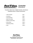
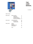
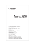
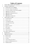
INSTALLATION and OPERATING
INSTRUCTIONS
Controller Unit ESP-MC
Introduction
Welcome to Rain Bird! Thank you for purchasing your new, state-of-the-art Rain Bird
controller. For more than six decades, Rain Bird has led the irrigation industry in meeting all of your water management needs by providing the highest quality products and
services available. Your new Rain Bird controller is designed to give you a lifetime of
on-site watering control.
1
The ESP-MC Controller
The Extra Simple Programming-MAXICOM Compatible series (ESP-MC) controller is a
stand-alone controller appropriate for residential or commercial use. Its easy-to-use
built-in computer offers four programs for up to 40 watering stations. The ESP-MC can
also be upgraded to function as a satellite controller that is part of the MAXICOM irrigation system.
For more information about using your controller with the MAXICOM system, see the
ESP-SAT Installation and Operating Instructions manual that comes with the ESP-SAT
and with the MAXICOM interface board (MIB) for the ESP-MC.
Special Features
The ESP-MC is available as a wall-mount (WM) model in 8, 12, 16, 24, 32, or 40 station capability. For information about pedestals, contact your Rain Bird distributor. All
ESP-MC models have the following special features:
• Anti-rust, corrosion-resistant design
• Four independent programs
• Cycle + Soak feature for water conservation and erosion control
• Program and time keeping during power outage
• Diagnostic circuit breaker that identifies a station with a short circuit
• Convenient Test Program
• Rain Delay from 1 to 99 days
• 365-day calendar with various scheduling options for watering cycles
• Option to set any day of the month as a non-watering day
• Cycle and fault indicator lights
• Easy-to-read liquid crystal display
• Optional moisture sensors that suspend watering when the soil is wet
• Universal remote-ready connections
• True independent day cycles by program
• Programmable program overlap
• Station timing from one minute to 12 hours
Packing List
Please check to make sure that you have all the items on the list. If any item is missing
or damaged, contact your Rain Bird distributor.
•1
•1
•2
•1
•1
•1
•1
Pre-assembled Controller in Wall Cabinet
Bag of Mounting Hardware
Keys
9-Volt Rechargeable Battery
Installation and Operating Instructions Manual
Mounting Template
Three-year Warranty Card
2
Chapter 1: Installation
This section of the manual explains how to mount your new ESP-MC controller on the
wall and how to connect the wiring.
Mounting the Controller
Before You Begin
Important: Before installing your controller, make sure that the area around you is
free from dirt and dust and that your hands and arms are clean. This will avoid contamination of the controller’s internal parts.
Warning! Do not let water or other liquids come in contact with any part inside the
metal cabinet.
Choosing a Location
When choosing the best location to install your wall-mount controller, please consider
the following:
Warning! This controller must be installed in compliance with local electrical codes.
ü Select an area, protected from vandalism, where the user can easily reach the controller. We recommend placing the controller in a utility room.
ü Select a location that has access to 120 volt AC electrical power (or the proper
electrical supply voltage outside the United States).
ü Choose a flat, stable, vertical surface, where you can mount the controller. Allow
sufficient conduit clearance for the electrical connections at the bottom of the metal
cabinet.
ü Allow 14” (35.9 cm) minimum clearance for the hinged cabinet door to swing fully to
the left.
What You Will Need
Before you begin installation, you will need the following tools:
ü
ü
ü
ü
ü
ü
ü
ü
ü
ü
Phillips Head Screwdriver
Slotted Head Screwdriver
Slotted Thin Blade Screwdriver
Wire Strippers
Lineman’s Pliers
Needlenose Pliers
Tape Measure
Marking Pencil
Electric Drill (or Hammer Drill if installing in masonry or concrete wall)
Nut Driver
3
Typical Wall-mount Installation
14” (36 cm)
minimum
11-1/4”
(28.8 cm)
Cabinet is
6-5/8” (17 cm)
11-3/8”
(28.2 cm)
To Fuse
Box
120 Volt AC
Wiring in Conduit
Wall
Floor
Valve Wiring in Conduit
4
Locate for
easy access
and for
comfortable
Chapter 1: Installation (Continued)
Removing the Controller’s Faceplate
In order to mount the controller, you must first remove the faceplate. To do so:
1. Remove the controller cabinet door from its two hinges by opening the door then
holding the bottom of the door and sliding up.
2. Pull out gently on the two white plastic snap latches on the right side of the faceplate, then swing the panel open.
3. Disconnect the two-wire harness from the terminal board by pressing the latch away
from the connector and pulling the connector away from the terminal board. Disconnect the wide gray ribbon cable by grasping the wide sides of the connector and
gently pulling the connector away from the terminal board.
4. Remove the faceplate from its hinges by pushing up gently on the panel until the
lower hinge comes up out of its hole. Slide the faceplate down and away to clear
the upper hinge from its hole. Set the faceplate aside.
5. Remove the white foam block from inside the controller. Remove the 9-volt battery
from the foam block.
Disconnecting ribbon wire
Step 1
Step 2
Disconnecting two-wire harness
Mounting the Controller on the Wall
Pick up the metal cabinet. Using a thin blade screwdriver, push out the three largest
plastic plugs at the back of the cabinet. The three new holes should form an up-side
down triangle.
1.Place the mounting template onto your mounting surface, then drill the holes.
2.Mount the controller cabinet with the mounting hardware supplied.
Note: The mounting materials and specific screws you need will vary according to the
kind of mounting surface (i.e. wood, cement, masonry, drywall, etc.).
(See illustrations on the following page.)
5
The illustrations below demonstrate Mounting the Controller.
Remove the faceplate from hinges
Three plastic plugs
Connecting the Controller
There are three types of connections you must make to your ESP-MC controller:
• connections to the field valves,
• grounding connections, and
• connections to the main power source.
You may also want to connect an optional sensor, which prevents watering during
rainfall or when the soil is moist.
This section of the manual contains instructions for all four types of connections.
Note: If you are installing an ESP-SAT controller, see the ESP-SAT Installation and
Operating Instructions Manual for information about connecting the controller to the
cluster control unit.
Important: All wiring must be installed and connected in accordance with local codes.
Connections to the Field Valves
Each valve that is controlled by the ESP-MC must have its own wire that is connected
to a numbered station terminal on the controller’s terminal strip. Each station terminal
is capable of operating two valves.
Important: The wires you use to connect the controller to the field valves must be approved for underground use. See the Rain Bird catalog for exact wire specifications.
Important: Do not install the valve wires in the same conduit as the wires to the main
power source.
6
To connect the valve wires:
1. Feed each valve wire up through the large hole on the bottom of the controller cabinet.
2. Strip 1/2” (1.3 cm) from the end of the valve wire. Insert the wire into the appropriate
station terminal. If the wire does not enter securely into the hole, press down on the
orange lever as you insert the wire.
Note: Each station has two holes (one above the other) because each station is capable of operating two valves.
3.Repeat for all used stations.
4.Attach the valve common wire to one of the two common terminals in the same way.
5. If your system includes a master valve or a 24 volt pump start relay, connect the
wire from that device to the MV (master valve) terminal on the controller the same
way you connected the other wires.
Note: MV2 (master valve 2) is enabled when any station operates. MV1 (master valve
Insertion of the Valve Wire:
Personal Wiring Notes:
_______________________________________________________________________________________________________
_______________________________________________________________________________________________________
_______________________________________________________________________________________________________
_______________________________________________________________________________________________________
_______________________________________________________________________________________________________
_______________________________________________________________________________________________________
_______________________________________________________________________________________________________
7
Grounding Connections
The ESP-MC is equipped with built-in electrical surge protection. For this system to
function, the earth ground terminal on the controller must be connected to a ground
rod that is driven into the earth.
Important: Use a #10 (6 mm) or #8 (10 mm) bare wire to connect the controller to the
ground-rod. Use a standard copper clad, 5/8" (1.6 cm) diameter, 8 ' (0.6 m) long rod.
To connect the ground wire,
1. Feed the ground wire up through the large hole at the bottom of the controller cabinet (the same hole used for the valve wires).
2.Loosen the screw on the copper earth ground terminal and place the ground wire
into the terminal. Tighten the screw so that the ground wire is secure.
Insertion of the Ground Wire:
Connections to the Main Power Source
The three main power input wires for the standard 117 volt, 60 Hz/AC transformer are
black, white, and green. The international version 230 volt, 50 Hz wires are black,
white, and green and yellow. These wires exit the controller through the smaller hole
at the bottom of the controller cabinet.
Important: The wires that connect the controller to the main power source must be installed in a conduit other than the one that contains the field wires.
Location of Junction Box:
8
To connect the power input wires to the main power source,
1. Connect a junction box to the transformer nipple. To do this, place the junction box
on the nipple, then thread the washer on. Twist it to tighten.
2. If you have the standard 117 volt, 60 Hz model, use wire nuts to connect the black
wire to the power source hot wire, the white wire to the common wire, and the green
wire to the ground wire.
OR
If you have a 230 volt, 50 Hz model, use wire nuts to connect the black wire to the
power source hot wire, and the white to the power source common wire. Connect
the green and yellow wire to the ground wire.
3.Close the junction box.
4.Install a conduit for the wires from the power source to the junction box.
Main Power Wire Connections:
Connections to an Optional Sensor
The ESP-MC controller allows you to connect an optional sensor. The ESP-MC works
with any open or closed switch sensor such as the Rain Bird Raincheck.
Important: The wires you use to connect the controller to the sensor must be approved for underground use. See the Rain Bird catalog for exact wire specifications.
Important: The sensor wires should be installed in a conduit other than the one that
contains the wires to the main power source.
To connect the sensor’s wires to the controller:
1.Remove the yellow jumper wire between the two sensor terminals.
2. Strip 1/2” (1.3 cm) from the end of the sensor wires. Insert one wire to each of the
sensor terminal holes. If the wire does not enter securely into the hole, press down
on the orange lever as you insert the wire.
9
Connecting the sensor’s wires to the controller (Continued)
3. Route the wires out of the controller through the large hole at the bottom of the controller cabinet
4.Connect the other end of the wires to the sensor’s valve common terminals or wires.
5.Follow the sensor’s directions for placing and connecting the sensor’s probes and
for setting the shutoff level, if appropriate.
Sensor Wire Connection (Step 1):
Putting the Controller Back Together
Congratulations! You have completed the mounting and wiring of your new ESP-MC
controller. To put the controller back together:
1. Replace the controller’s face plate by slipping it into the hinges.
2. Plug the two-wire connector and the ribbon cable connector back into the terminal
board.
3. Detach the recharging clip from its retainer at the back of the face plate. Snap the
recharging clip onto the 9 volt battery supplied. Then push the battery into the battery holder.
The ESP-MC fully charges the nickel metal hydride, 9 volt battery in about 48 hours
and continues to charge the battery whenever the controller is supplied with power.
The 9 volt battery provides power for keeping track of what cycle is in progress
when there is a power outage. The 9 volt battery also allows the controller to be
programmed when the face plate is detached from the cabinet. This feature lets the
installer walk a site while setting watering times and schedules.
Note: The ESP-MC also has a built-in lithium battery that provides for non-volatile
program memory.
Warning! Do not use an alkaline battery in the controller; alkaline batteries can cause
an explosion.
4.Re-attach the controller door to its hinges.
10
Chapter 2: Programming & Operation
Using the buttons and dial on the controller's faceplate, you can set up the ESP-MC to
operate automatically. You can also run the controller manually without making
changes in the programs you have set.
This section will guide you through the use of the controller's buttons and dial and will
give you step-by-step instructions for setting up the four programs to suit your needs,
as well as instructions for operating the controller manually.
Familiarizing Yourself with the Controller’s Faceplate
Before beginning to program or operate your controller, take a moment to familiarize
yourself with the controller’s faceplate. The following information contains a short description of each of the buttons and indicators.
WATERING SUSPENDED BY SENSOR
This light is on when watering has been suspended by a sensor.
SENSOR OFF/ACTIVE
If you want the sensor to be active, set the switch to ACTIVE. If you wish to override
the sensor or there is no sensor connected to the controller, set the switch to OFF.
p / ON
Press to turn a setting on or to advance the setting in the display.
q / OFF
Press to turn a setting off or to decrease the setting in the display.
PGM
Press to change the program indicator in the display. The indicator cycles through
programs A, B, C, and D.
MAN START/ADV.
Press to advance to the next setting in the display or to start an operation.
FAULT RESET
Press to clear the fault reading from the display. Press this button after you have fixed
the short circuit indicated by the diagnostic fault indicator in the display.
STAND ALONE/MAXICOM
If you want your controller to function as a stand-alone unit, set this switch to STAND
ALONE. If you want it to function as a satellite connected to the MAXICOM system, set
this switch to MAXICOM.
PUMP/MV STATUS
This light is on when the Master Valve 1 (MV1) circuit is enabled for the active station.
STATION STATUS
This light is on when a valve is active.
LINKED TO MAXICOM
This light is on when the STAND ALONE/MAXICOM switch is in the MAXICOM position and the controller is physically linked to the MAXICOM system.
11
Buttons and indicators (Continued)
EVEN DAY CYCLE
This light is on when the controller’s active program is set to water on even days of the
month.
ODD DAY CYCLE
This light is on when the controller’s active program is set to water on odd days of the
month.
CYCLICAL DAY CYCLE
This light is on when the controller’s active program is set to water in a cycle with a
specified number of days.
CUSTOM DAY CYCLE
This light is on when the controller’s active program is set to water on specific days of
the week.
AUTO
Set the dial here to run the controller automatically on the programs you set.
STATION WATERING TIME
Set the dial here to set the length of an individual station’s watering time.
WATERING START TIME
Set the dial here to set a program’s watering start times. Eight start times are available
for each program.
MV PUMP START
Set the dial here to enable or disable Master Valve 1 (MV1) for a particular station.
PROGRAM OVERLAP
Set the dial here to set programs to either stack or overlap. The default for all programs is stack.
TIME/CALENDAR
Set the dial here to set the time and calendar.
EVENT DAY OFF
Set the dial here to set optional day(s) off within the month.
RAIN DELAY
Set the dial here to delay watering for a specified number of days.
MON — SUN
Set the dial to the day of the week to turn that day off or on when setting a custom program cycle.
CUSTOM
Set the dial here to set a program cycle to water on specific days of the week.
CYCLICAL
Set the dial here to set a program cycle to water at specific intervals such as every
day, every second day, every third day, etc.
ODD DAYS
12
Buttons and indicators (Continued)
EVEN DAYS
Set the dial here to set a program cycle that waters on even days of the month.
WATER BUDGET
Set the dial here to set the water budget percentage for a program. 100% is the default.
CYCLE + SOAK
Set the dial here to break a station’s watering time into intervals to conserve water and
prevent erosion.
TEST PROGRAM
Set the dial here to set and start a test program cycle for all stations.
MANUAL WATERING
Set the dial here to water a station manually.
OFF
Set the dial here to shut the controller and its valves down, such as during the winter
months.
Programming the Controller
This section of the manual contains instructions for programming your ESP-MC controller. The controller comes from the factory without a pre-set default program.
Before you begin programming, it is a good idea to chart your watering schedule on a
piece of paper, taking into account the schedule for all stations and how often you
want to repeat the schedule.
Setting the Clock and Calendar
In order to program the controller, you must first set the controller’s internal clock and
1. Rotate the dial to TIME/CALENDAR. The hour
digits in the display flash, indicating that they
are ready to be set.
2. Use the arrow keys to set the hour to the current time. If you have a 60 Hz model, as you
pass 12:00 the am/pm designation changes.
Note: The 60 Hz model displays time in the 12
hour am/pm mode. The 50 Hz model displays
time in the 24 hour military mode.
3. Press MAN START/ADV. The minute digits
flash, indicating that they are ready to be set.
13
AM
4.
Use the arrow keys to set the minutes to the
current time.
5.
Press MAN START/ADV.
A new display appears with the day, month
and year. The month is flashing, indicating
that it is ready to be set.
6.
Use the arrow keys and the MAN START/
ADV key to set the month, day, and year the
same way you set the hour and minutes.
7.
Press MAN START/ADV to return to the time
of day display. The hour continues to flash
as long as the dial is left at TIME/CALENDAR.
DAY
PM
8.
Return the dial to AUTO. The display shows
the day of the week and time of day.
Setting Up a Program
There are four program settings available with the ESP-MC: A, B, C, and D. You can
set each program to operate according to your specifications. When you set up a program, you:
• select the program,
• choose a cycle setting for the program, and
• assign stations and set the station’s watering durations and start times.
Note: It is easier to select a program and program it completely. Jumping from program to program can be confusing.
Step one: Selecting a program
1.
Press PGM to cycle through the available
programs. The program indicator on the far
left side of the display changes.
A
PGM
Step two: Selecting the cycle
Each program can operate in one of four cycle modes:
• CUSTOM waters on the days of the week you select
• CYCLICAL waters according to a cycle with a specified number of days.
• ODD waters only on odd days of the month.
• EVEN waters only on even days of the month.
Note: All programs default to the custom cycle.
14
To set a custom cycle:
1.
Rotate the dial to CUSTOM. The display
shows the program and CUSTOM. The display shows USED if the program is active
and using a different cycle mode. If so, you
can override the previous setting.
2.
If the program you want is not displayed,
press PGM until it is.
3.
Press ON. The display shows CUSTOM and
the custom light on the faceplate illuminates.
4.
Rotate the dial to the first day of the week
and use the ON and OFF keys to turn the
day on or off. The display shows the day and
the ON/OFF setting.
5.
A
PGM
DAY
A
PGM
Repeat step 4 for all the days of the week
you want to change.
Return the dial to AUTO. The controller returns to the time of day display and waters
on the days you have specified.
To set a cyclical cycle:
6.
1.
Rotate the dial to CYCLICAL. The display
shows the number of days remaining and the
number of days in the cycle. The number of
days in the cycle is flashing, indicating that it
is ready to be set. The display shows USED
if the program is active and using a different
cycle mode. If this is the case, you can override the previous setting.
2.
If the program you want is not displayed,
press PGM until it is.
3.
Press ON. The cyclical display shows and
the cyclical light on the faceplate illuminates.
4.
Use the arrow keys to set the number of
days in the cycle. For example, if you set a
3-day cycle, the controller skips two days
and waters on the third day.
5.
Press MAN START/ADV to toggle to the left
side of the display. The number of days remaining in the cycle flashes, indicating that it
is ready to be set.
6.
Use the arrow keys to set the number of
days remaining before the next watering day.
This tells the controller where today is in the
cycle you have just set.
15
A
PGM
DAYS REMAINING
DAY CYCLE
Setting a cyclical cycle: (Continued)
7.
Return the dial to AUTO. The controller returns to the time of day display and waters
on the days you have specified.
To set an odd or even cycle:
1.
Rotate the dial to ODD DAYS or EVEN
DAYS. The display shows the program and
ODD or EVEN. The display shows USED if
the program is active and using a different
cycle mode. If this is the case, you can override the previous setting.
2.
If the program you want is not displayed,
press PGM until it is.
3.
Press ON. The display shows either ODD or
EVEN and the corresponding light on the
faceplate illuminates.
4.
Return the dial to AUTO. The controller returns to the time of day display and waters
on the days you have specified.
A
PGM
Note: The 31st day of the month defaults to ON,
so if you do not want to water on the 31st, you
must set that day to OFF.
Step three:
Setting the length of a station’s watering time
Within the program you are setting, you can set
the length of a station’s watering time from 0 minutes to 12 hours. Set the time in one-minute increments for up to two hours; set it in 10-minute
increments from two hours to 12 hours.
To set the length of a station’s watering time,
1.
2.
Rotate the dial to STATION WATERING
TIME. The display shows the program, the
station number, and the length of watering
time. The station number is flashing, indicating that it is ready to be set. If the station is
included in any other program, the controller
will let you know by replacing the length of
watering time with USED.
If the program you want is not displayed,
press PGM until it is.
16
A
PGM
STATION
WATER TIME
3.
Use the arrow keys to display the station
number you wish to set.
4.
Press MAN START/ADV to toggle to the right
side of the display. The length of watering
time flashes, indicating that it is ready to be
set.
5.
Use the arrow keys to set the length of time.
If USED is displayed, you can still set the
length of time. (You can include the same
station in different programs and give that
station different lengths of watering time.)
6.
Return the dial to AUTO. The display shows
to the time of day.
Step four: Setting watering start times
For each program, you may assign up to eight
start times per day, available on the quarter hour.
To do so:
1.
Rotate the dial to WATERING START TIME.
The display shows the program, the number
of the start time, and the start time. The number of the start time is flashing, indicating
that it is ready to be set.
2.
If the program you want is not displayed,
press PGM until it is.
3.
Use the arrow keys to select one of the eight
start times.
4.
Press MAN START/ADV to toggle to the right
side of the display. The start time flashes, indicating that it is ready to be set.
5.
Use the arrow keys to select a start time.
Start times are available in fifteen minute intervals, with an OFF setting available between the 11:45 pm and 12:00 am options on
the 60 Hz model (and between 23:45 and
24:00 on the 50 Hz model).
17
A
PGM
AM
Note: Start times are displayed in chronological
order. If a start time is deleted from the order by
setting it to OFF, all later start times are automatically moved down one start time number. When
a start time is added to any start time number,
the controller automatically reorganizes the times
so that times appear in chronological order. This
reorganizing only occurs after the dial has been
moved off the WATERING START TIMES position.
6.
If you want to set additional start times, press
MAN START/ADV to toggle back to the left
side of the display and the next available
start time number. Set the next start time in
the same fashion as the first.
7.
Return the dial to AUTO. The controller returns to the time of day.
Step five:
Setting programs to stack or overlap
You can set a program to stack (run one at a
time) or overlap (run simultaneously). The ESPMC can run up to nine valves simultaneously.
The default setting is to stack all programs. To
set programs to stack or overlap:
1.
Rotate the dial to PROGRAM OVERLAP.
The display shows the program, and STACK
or OVERLAP.
2.
If the program you want is not displayed,
press PGM until it is.
3.
Use the arrow keys to set the program to either STACK or OVERLAP.
4.
Return the dial to AUTO. The controller returns to the time of day display.
Step six: Setting the MV/PUMP start
The ESP-MC has two master valve terminals on
its circuit board. MV2 (master valve 2) is enabled
when any station operates. MV1 (master valve 1)
can be enabled or disabled for each individual
station.
18
A
PGM
To set MV1 for a station:
1.
Rotate the dial to MV PUMP START. The
display shows the station number and MV
ON or OFF. The station number is flashing,
indicating that it is ready to be set.
2.
Use the arrow keys to select the station number.
3.
Press MAN START/ADV to toggle to the right
side of the display. The ON or OFF flashes,
indicating that it is ready to be set.
4.
Press either the ON or OFF key.
5.
If you want to set another station, press MAN
START/ADV to toggle back to the left side of
the display to continue setting stations.
6.
When you are finished setting stations, return the dial to AUTO. The controller returns
to the time of day.
A
PGM
STATION
Setting Rain Delay
The ESP-MC allows you to delay watering for a
specified number of days. The Rain Delay setting
affects all programs. To set a Rain Delay:
RAIN DELAY
1.
Rotate the dial to RAIN DELAY. The display
shows RAIN DELAY and the number of days
until the next cycle
2.
Use the arrow keys to set the number of
days to the next cycle.
3.
Return the dial to AUTO. The controller returns to the time of day display and will delay
watering for the number of days you have
specified.
Note: To cancel a Rain Delay, reset the number
of days to 0.
19
DAY
Setting Cycle + Soak
The Cycle + Soak feature is designed to conserve water that might puddle in tight soils such
as clay, or end up as runoff on slopes. Cycle +
Soak lets you break up the total watering time of
a station into shorter cycles with a soak time between cycles. You set the maximum watering
time length and the minimum soak time. This
setting affects all programs in which the station is
included.
For example, if you want to water a station for a
total of 20 minutes, but runoff begins to occur after 5 minutes, you can set the station for 5minute maximum cycles, and a minimum of 25
minutes between cycles. While the station is in
soak mode, the controller operates other stations
in the program.
Note: If there is nothing left for the controller to
do but wait until a soak time elapses, the display
shows SOAK.
Note: The Test program does not respond to Cycle and Soak settings.
To set Cycle + Soak:
1.
Rotate the dial to CYCLE + SOAK. The display shows the station number, the length of
time to water, and the length of time to soak.
The station number is flashing, indicating
that it is ready to be set.
2.
Use the arrow keys to select the station.
3.
Press MAN START/ADV. The length of time
to water flashes, indicating that it is ready to
be set.
4.
Use the arrow keys to set the maximum
length of time to water from 1 to 60 minutes.
5.
Press MAN START/ADV. The length of time
to soak flashes, indicating that it is ready to
be set.
6.
Use the arrow keys to set the minimum
length of time to soak for from 1 to 60 minutes.
20
STATION
WATER TIME
STATION
WATER TIME
7.
If you want to set Cycle and Soak for another
station, press MAN START/ ADV again.
8.
When you have finished setting Cycle and
Soak, return the dial to AUTO. The controller
returns to the time of day.
Setting the Water Budget
The water budget feature allows you to increase
or decrease a program’s watering time in increments of 1% without having to reset the timing for
each station in the program. You can set the
budget for 0% to 300%. You can use the 0% setting to shut a program down temporarily. To set
the water budget:
1.
Rotate the dial to WATER BUDGET. The
display shows the program and the water
budget percentage.
2.
Press PGM until the program you want is
displayed.
3.
Use the arrow keys to set the percentage.
4.
Return the dial to AUTO. The controller returns to the time of day display. The default
percentage for all programs is 100%. When
the water budget for a program is set to other
than 100%, WATER BUDGET will show in
the display whenever that program is selected.
WATER BUDGET PERCENT
A
PGM
Setting Event Day Off
The Event Day Off feature allows you to omit
temporarily a calendar day or days from the watering cycle. After a calendar day passes, that
day returns to the default setting. The default for
all days is ON. If the 31st is set to OFF, it remains off until it is set to ON. This is to accommodate odd day watering cycles which do not allow watering on the 31st and 1st. To set a day
off:
1.
Rotate the dial to EVENT DAY OFF. The display shows the day of the month on the left,
and the ON or the OFF setting on the right.
The day of the month is flashing, indicating
that it is ready to be set.
21
DAY
2.
Use the arrow keys to set the day of the
month you wish to change.
3.
Press MAN START/ADV to toggle to the right
side of the display. The ON/OFF setting
flashes, indicating that it is ready to be set.
4.
If you are setting the day to on press ON; if
you are setting the day to off, press OFF.
5.
Return the dial to AUTO. When a day off arrives, the display shows NON (for nonwatering day) and the controller does not allow watering.
Operating the Controller
Once you have programmed the ESP-MC, operating the controller is easy. You may choose to
operate it completely automatically or to operate
it manually from time to time. When you operate
the ESP-MC manually, you do not disturb any of
the programmed instructions.
Operating Automatically
To operate the controller automatically:
1.
Rotate the dial to AUTO. The controller runs
each of the programs as you have specified.
Operating Manually
There are a number of functions you can perform
manually. Each one is described in this section.
Operating a program or programs manually
You can select, start, and manually advance programs for semi-automatic operation. To do so,
1.
Rotate the dial to AUTO. The display shows
the day of the week and the time of day.
2.
Press PGM until the program you wish to operate is displayed.
3.
Press MAN START/ADV to start the selected
program. You must press MAN START/ADV
before PGM disappears.
22
DAY
PM
4.
If you want to operate more than one program, press PGM to select another program
and press MAN START/ADV again. The second program runs when the first is complete.
You can stack all four programs in this way.
Operating a station or stations manually
You can initiate one-time operation of a single
station or a combination of stations. If you run
more than one station, they will run in the order
in which they were selected. To operate one station or multiple stations:
1.
Rotate the dial to MANUAL WATER. The
display shows the program, the station number, and any watering time remaining on that
station.
2.
Press PGM until the program you want is
displayed.
3.
Use the arrow keys to select the station you
want to operate.
4.
Press MAN START/ADV to start the selected
station.
5.
If you want to operate more than one station,
repeat steps 2 through 4.
6.
Return the dial to AUTO. The controller returns to the time of day display and the stations operate in the sequence they were selected. After the stations are finished watering, the controller returns to the automatic
mode.
Note: When you operate a station manually, you
cannot change the amount of time the station will
water. You must water for the amount of time already programmed.
23
A
PGM
STATION
WATER TIME REMAINING
Using the test program
The test program allows you to run a test cycle
for all the stations on a particular program. It also
lets you decide how long the test will last.To set
and then start a test program:
1.
Rotate the dial to TEST PROGRAM. The display shows the program, TEST, and the
length of time to test.
2.
Press PGM until the program you want to
test is displayed.
3.
Use the arrow keys to set the length of time
to test each station for from 1 to 99 minutes.
4.
Press MAN START/ADV to start the test.
The test time flashes and the controller runs
the test program immediately, suspending
any work in progress.
5.
If you want to add other programs to the test,
with the dial set to TEST PROGRAM, press
PGM to select the program. Then press MAN
START/ADV to stack the new program after
the first one. You can stack four programs.
Note: To cancel the test on all programs, rotate
the dial to OFF.
6.
Rotate the dial back to AUTO to return to
normal programming and operation.
Using the Sensor Option
The ESP-MC allows you to connect a sensor that
can disable watering. When a sensor is connected to the ESP-MC and it suspends watering,
the sensor light on the front panel illuminates. To
enable the sensor:
1.
Set the sensor switch to ACTIVE. The controller operates as usual until the sensor suspends watering and the controller display
shows SUSPENDED BY SENSOR.
24
A
PGM
Using the Diagnostic Circuit Breaker
The ESP-MC is equipped with a circuit overload protection system. This system
causes the controller to skip over a station that has an electrical short circuit, rather
than blow a fuse which would shut down the entire system.
When the controller tries to start a station that has a short circuit, the electronic circuit
breaker senses the short circuit and skips that station. The controller skips to the next
station, but flashes the skipped station number and FAULT in the display.
Once you have corrected the problem, push the FAULT RESET button to clear the
flashing fault indicator.
Note: The diagnostic circuit breaker allows detection on all valves, including the master valve.
Appendix
Scheduling Chart
Before you begin programming, it is a good idea to chart your watering schedule, taking into account the schedule for all stations and how often you want to repeat the
schedule. A sample schedule appears below.
25
Glossary
Circuit board
One of the etched, copper clad sheets of insulating material onto which electronic
components and terminals are assembled. Controllers contain circuit boards.
Controller
A device that sends a 24 VAC power signal to the field solenoid valves.
CPU board
The central processing unit circuit board inside the controller.
Default setting
The start-up settings for the controller. The default settings cannot be changed.
ESP-MC
Extra Simple Programming — MAXICOM Compatible series, an 8, 12, 16, 24, 32, or
40 independent station controller that is a stand-alone unit, but is upgradable to a
satellite controller linked to MAXICOM.
GPM
Gallons per minute.
Hardwire
Communication cable used to transmit data between devices.
Liquid crystal display (LCD)
The illuminated display used on the faceplate of most controllers.
Manual
Requires user input, rather than being automatically performed by the PC program.
Master valve (MV)
An electrically operated valve located on a system’s main line that controls the flow of
water to all other electric and manual valves downstream of it.
Master valve circuit
An electrical circuit located on many controllers used to control a master valve. Regardless of what station is on at the controller, the master valve circuit produces voltage to control the master valve. When all of the stations on the controller are off, the
master valve circuit turns off.
Monitor
To observe conditions in and around the irrigation system and send the information to
the different components in the system for appropriate action.
Satellite
A controller in the field capable of communicating with the Cluster Control Unit (CCU).
Satellite controller
Same as satellite.
Sensor system
An optional addition to the controller that disables watering. Examples are the Rain
Bird Aquamiser, Intellisense, Rain Check, and Rain/Freeze Check.
Site
A single, remote irrigated area controlled by a CCU. For example, one park is a site in
26
Soil infiltration rate
The rate at which soils accept water.
Solenoid
A portion of a field valve that receives a 24 VAC electrical current from the controller.
Station schedule
The watering schedule for one of the stations controlled by the controller.
Valve
A manual or electrically operated device used to control flow of water in an irrigation
system.
Water budget
A feature available in some controllers and central control systems allowing adjustment of water application times without reprogramming each station or irrigation
schedule.
Watering cycle
MAXICOM Central Control System
1.Central
Computer
Central Computer
2.Computer
data path
options
Trunk
Cellular
Phone
3.CCU
6.Stations
Point to point
Radio
CCU
4.Satellite
data path
options
5.Field
Devices
Hardwire/
Short-haul
CCU
Two-wire Path (TW)
Satellite
Controller
Valve
Valve
MAXILink Radio (LINK/R)
Satellite
Controller
Decoder
Sensor
Switch
or
7.Weather
Station
Weather Station
27
Valve
Valve
Switch
Service Information
In the unlikely event this equipment should malfunction, all repairs should be performed by an authorized Rain Bird MAXICOM Authorized Service Center.
For information on MAXICOM Authorized Service Centers, contact Rain Bird at:
Rain Bird Sales, Inc.
Customer Support Center
6640 S. Bonney Ave.
Tucson, AZ 85706
1-800-RAIN BIRD
(520) 434-6289 FAX
RAIN
BIRD
PREFERRED BY PROFESSIONALS WORLDWIDE
28