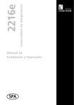
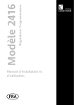
1
REMIO/TPO/ENG.A5
6/11/00
8:42
Page 1
REMIO
Communicating interface for the
TE range of power units
TPO Version: Time Proportioning Output
Communications protocols
Modbus®
Profibus-DP
DeviceNet™
User Manual
© Copyright Eurotherm Automation 1998
All rights reserved. All reproduction or transmission in any form
or using any procedure (electronic or mechanical,including
photocopying or recording) without written authorisation from
EUROTHERM is strictly prohibited.
Part No. HA 175874 ENG - Issue 2.2 - Printed in France 10/2000
i
REMIO/TPO/ENG.A5
6/11/00
8:42
Page 2
CONTENTS
Relevant European Directives
Chapter 1 Identifying The Interface . . . . . . . . .1-1
Chapter 2 Wiring . . . . . . . . . . . . . . . . . . . . . . . . .2-1
Chapter 3 Digital Communications . . . . . . . . . .3-1
Chapter 4 Configuration . . . . . . . . . . . . . . . . . . .4-1
Chapter 5 Operation . . . . . . . . . . . . . . . . . . . . . .5-1
ii
REMIO/TPO User Manuel
REMIO/TPO/ENG.A5
6/11/00
8:42
Page 3
RELEVANT EUROPEAN DIRECTIVES
SAFETY
REMIO products are not affected by the European Low Voltage Directive of 73/23/EEC of
19/2/73 (amended by the Directive 93/68/EEC of 22/7/93).
ELECTROMAGNETIC COMPATIBILITY (EMC)
(For industrial environments only, must not be used in domestic environments)
Eurotherm certifies that REMIO products, installed and used in compliance with this User
Manual, meet the following EMC test standards and enable the system which incorporates them
to comply with the EMC Directive, as far as the REMIO products are concerned.
EMC test standards
Immunity
Emission
Generic standard:
Test standards:
EN50082-2
EN 61000-4-2, EN 61000-4-4, EN 61000-4-3,
EN 61000-4-6, ENV 50204
Generic standard: EN 50081-2
Radiated: EN 55011 Class A
EMC Guide
In order to help you reduce the effects of electromagnetic interference depending on the product
installation, Eurotherm can supply you with the 'Electromagnetic Compatibility' Installation Guide
(part no. HA 025464 ENG).
This guide lists the rules generally applicable for EMC.
VALIDATION BY INDEPENDENT BODY
Eurotherm has validated the compliance of REMIO products with EMC test standards through
product design and laboratory testing.
REMIO/TPO User Manuel
iii
REMIO/TPO/ENG.A5
6/11/00
8:42
Page 4
Personnel
The installation, configuration, commissioning and maintenance of the REMIO
interface must only be carried out by personnel qualified and trained to work
with low voltage electrical equipment in an industrial environment.
Independent alarm
Given the safety regulations concerning personnel and property, and the value of the
equipment controlled by REMIO and the power units, we recommend the use of
independent safety devices (alarms), which should be tested regularly.
Eurotherm can supply various types of alarm device for this purpose.
Further information
For any further information, or if in doubt, please contact Eurotherm Controls where
qualified staff are available to advise or assist you with the commissioning of your
installation.
iv
REMIO/TPO User Manuel
REMIO/TPO/ENG.A5
6/11/00
8:42
Page 5
Identifying the unit
Chapter 1
IDENTIFYING THE REMIO INTERFACE
Contents
Page
General introduction.................................................................................1-2
Front panel of unit....................................................................................1-4
Technical specification...............................................................................1-7
Product code............................................................................................1-9
Example of product code........................................................................1-10
Identification label..................................................................................1-10
REMIO/TPO User Manuel
1-1
REMIO/TPO/ENG.A5
6/11/00
8:42
Page 6
Identifying the unit
Chapter 1 IDENTIFYING THE INTERFACE
GENERAL INTRODUCTION
The REMIO communications interface is designed to control several power units from the
TE range via the digital communications bus.
This User Manual describes the use of the TPO version of REMIO interfaces, with three
communications protocols:
Modbus®, Profibus-DP, DeviceNet™
The REMIO/TPO interface receives setpoints via the communications bus and transmits them
to the power units which it controls, in the form of a modulated logic output signal.
REMIO is a modular product, comprising:
• a Base Module and
• two Optional Modules (Expansion Modules).
The Base Module pr ovides communications bus and power supply connections and the
necessary configurations.
In the TPO version, each module (the Base Module as well as the Expansion Modules)
comprises 16 outputs, designed to transmit the setpoints received by the communications bus
to the power units in the form of a logic output signal with dual-mode time proportioning
(TPO).
The maximum output count for the REMIO is 48.
REMIO TPO modules allow the use of two power unit firing modes, depending on the power
supply used:
• Fast cycling with a 24Vdc power supply
• Advanced Single-cycle with a 24Vac supply.
The LEDs on the REMIO front panel show the state of the communications bus and of the
module power supply.
REMIO is mounted on a symmetrical DIN rail.
Detailed operation of the communications bus is described in the following manuals:
• REMIO/Modbus® Communications Manual
(part no. HA 175814 ENG)
• REMIO/Profibus-DP Communications Manual
(part no. HA 176078 ENG)
• REMIO/DeviceNet™ Communications Manual
(part no. HA 176272 ENG)
Operation of the power units controlled is described in the User Manuals:
• TE10S/DC (part no. HA174780 ENG)
• TE10S/PLF (part no. HA174784 ENG)
• TE200S
(part no. HA175921 ENG)
• TE300
(part no. HA175437 ENG)
1-2
REMIO/TPO User Manuel
REMIO/TPO/ENG.A5
6/11/00
8:42
Page 7
Identifying the unit
Figure 1-1 Overview of REMIO/TPO Base Module (Modbus® protocol)
REMIO/TPO User Manuel
1-3
REMIO/TPO/ENG.A5
6/11/00
8:42
Page 8
Identifying the unit
FRONT PANEL OF UNIT
The following diagrams show:
• the front panels of the REMIO/TPO unit in various physical configurations
- without optional modules: Base Module version
- with optional modules (maximum configuration)
• the front panel labels which correspond to each protocol.
Figure 1-2 Front panel of REMIO/TPO (Profibus-DP protocol) in Base Module version
1-4
REMIO/TPO User Manuel
REMIO/TPO/ENG.A5
6/11/00
8:42
Page 9
Identifying the unit
Figure 1-3A REMIO/TPO Base Module label in Modbus® protocol
Figure 1-3B REMIO/TPO Base Module label in DeviceNet™ protocol
Figure 1-3C REMIO/TPO Base Module label in Profibus-DP protocol
REMIO/TPO User Manuel
1-5
REMIO/TPO/ENG.A5
6/11/00
8:42
Page 10
Identifying the unit
Figure 1-4 Front panel of REMIO/TPO (Modbus® protocol) in maximum configuration
(48 outputs)
1-6
REMIO/TPO User Manuel
REMIO/TPO/ENG.A5
6/11/00
8:42
Page 11
Identifying the unit
TECHNICAL SPECIFICATION
The REMIO communications interface is designed to drive various thyristor power
units controlling resistive industrial loads and short-wave infrared elements.
Hardware configuration
Base Module
Expansions 1 or 2
2 ports each with 8 outputs providing dual-mode time
proportioning logic output signals (TPO).
- Configuration mini-switches
- Power supply connector
- Communications bus connector
2 ports each with 8 outputs providing dual-mode time
proportioning logic output signals (TPO).
Port specification
TPO outputs
Common excitation potential
Resolution
Connectors
Voltage 20V, modulated
Time proportioning from 0 to 100%
Maximum current limited to 6.5mA
Possible to connect two solid state relay (SSR) inputs
from the TE range in series on each TPO output
For all TPO outputs a common +20Vdc supply is
available on each port.
8 bits (0.4%)
Plug-in, M3 screws
Communications
Communications protocol
Bus
Transmission baud rate
Modbus or Profibus-DP or DeviceNet™
(specify when ordering)
2-wire
Standard RS485 (Modbus® or
Profibus-DP) or CAN Bus
(DeviceNet™)
Modbus:
9.6k or 19.2kbaud (configurable)
Profibus-DP:
auto Baud rate detection up to
1.5Mbaud
DeviceNet™:
125k, 250k or 500kbaud
(configurable)
Diagnostics
Communications
LED indication
State of communications bus
State of REMIO and of TPO outputs
Bus state, REMIO state (DeviceNet)
Module power supply
Power supply
Voltage
Consumption
REMIO/TPO User Manuel
24Vdc non-polarised (-15%, +25%) or
24Vac (-15%, +10%), 47 - 63 Hz
Depends on number of outputs used (20VA max)
1-7
REMIO/TPO/ENG.A5
6/11/00
8:42
Page 12
Identifying the unit
Thyristor firing
General
All base module and optional module outputs
are modulated in the same way:
Burst-firing or Intelligent Single-cycle
By type of supply volta ge
DC supply voltage (24Vdc): Burst-firing
Number of firing or non-firing cycles at 50%
setpoint: 8 cycles
AC supply voltage (24Vac): Intelligent Single-cycle
Firing or non-firing by a complete number of
half-cycles
DC component absent
Firing starts and ends at zero voltage
Selection
Firing modes
Switching
Environment
Operating temperature
Storage temperature
Power supply circuit protection
External wiring
Operating atmosphere
Humidity
Pollution
0°C to +45°C at 2000m max. altitude
-10°C to +70°C
External 2A fuse
To be carried out in accordance with Standard IEC 364
Non-explosive, non-corrosive & non-conductive
RH: 5% to 95%, non-condensing and non-streaming
Pollution degree 2 permissible, defined by IEC 664
Physical dimensions
Dimensions (mm)
Mass (kg)
Height: 115 (122: including connectors)
Depth: 92.5
Width: Base module = 87.5
One Optional Module = 17.5
Maximum configuration = 122.5
0.9 (maximum configuration)
Warning!
EUROTHERM has made every effort to ensure that the specification g iven in this manual is as accurate and up to
the minute as possible. Ho wever, in order to maintain our 'leading edge',it may be necessary to make certain
changes or omissions to our specification.
We cannot be held responsible for any dama ge to persons or property or for any financial loss or costs arising
from this.
1-8
REMIO/TPO User Manuel
REMIO/TPO/ENG.A5
6/11/00
8:42
Page 13
Identifying the unit
PRODUCT CODE
REMIO / Base Module / Exp.1 / Exp.2 / Protocol / Transmission rate / Manual // 00
Base Module
Code
16 dual-mode* time-proportioned outputs
TP
Expansion Module 1
Code
Expansion 1 provides
(16 dual-mode* time-proportioned outputs)
Without Expansion 1
TP
-
Expansion Module 2
Code
Expansion 2 provides
(16 dual-mode* time-proportioned outputs)
Without Expansion 1 or 2
TP
-
Communications protocol
Code
Modbus®
Profibus-DP
DeviceNet™
MOP
PFP
DNP
Transmission rate
Code
Modbus® :
96
192
AUTO
125
250
500
Profibus-DP :
DeviceNet™ :
9.6kbaud
19.2kbaud
(auto Baud rate detection)
125kbaud
250kbaud
500kbaud
Manual language
Code
French
English
FRA
ENG
*) The firing mode of TPO module outputs is determined by the power supply type:
24Vac = Advanced Single-cycle; 24Vdc = Fast Cycling
REMIO/TPO User Manuel
1-9
REMIO/TPO/ENG.A5
6/11/00
8:42
Page 14
Identifying the unit
EXAMPLE OF PRODUCT CODE
Example 1
Number of TE10S solid state relays (SSRs) controlled by REMIO : 15
(15 < 16 = without Expansion Modules)
Communications used:
Modbus® at 9.6kbaud
Firing mode:
Advanced Single-cycle
User Manual:
English
Code:
REMIO / TP / - / - / MOP / 96 / ENG // 00
Power supply : 24Vac
Example 2
Number of TE10S solid state relays controlled by REMIO : 40
(2 x 16 = 32 < 40 < 3 x 16 = 48 fi 2 Expansion Modules)
Communications used:
Profibus-DP
Firing mode:
Fast Cycling
User Manual:
French
Code:
REMIO / TP / TP / TP / PFP / AUTO / FRA // 00
Power supply : 24Vdc
IDENTIFICATION LABEL
An identification label gives all the necessary information on REMIO characteristics, as
shipped from the factor y. The identification label is located on the left side of the unit.
Figure 1-5 Example of REMIO identification label (corresponds to coding example No. 1)
Warning!
Following any re-configuration on the part of the
user, there is no guarantee that the unit will
correspond to the label information.
1-10
REMIO/TPO User Manuel
REMIO/TPO/ENG.A5
6/11/00
8:42
Page 15
Wiring
Chapter 2
WIRING
Contents
Page
Installation - safety . . . . . . . . . . . . . . . . . . . . . . . . . . . . . . . . . . . . . . . .2-2
Wiring – safety . . . . . . . . . . . . . . . . . . . . . . . . . . . . . . . . . . . . . . . . . .2-2
Terminal block labelling . . . . . . . . . . . . . . . . . . . . . . . . . . . . . . . . . . . .2-3
Control . . . . . . . . . . . . . . . . . . . . . . . . . . . . . . . . . . . . . . . . . . . . .2-3
Power supply . . . . . . . . . . . . . . . . . . . . . . . . . . . . . . . . . . . . . . . .2-9
Communications bus . . . . . . . . . . . . . . . . . . . . . . . . . . . . . . . . . .2-10
Screening example . . . . . . . . . . . . . . . . . . . . . . . . . . . . . . . . . . . . . .2-12
Wiring example of REMIO/ TE assembly . . . . . . . . . . . . . . . . . . . . . . .2-13
REMIO/TPO User Manuel
2-1
REMIO/TPO/ENG.A5
6/11/00
8:42
Page 16
Wiring
Chapter 2 WIRING
INSTALLATION - SAFETY
Danger!
REMIO units must be installed by qualified personnel trained to work with low
voltage electrical equipment in an industrial environment.
Units must be installed in fan-cooled electrical cabinets, to ensure that
condensation and pollution are excluded.
The cabinet must be closed and bonded to the protective earth in accordance with
Standards NFC 15-100, IEC 364 or cur rent national Standards.
It is recommended that a fan-failure detection device or a thermal safety cut-out
should be fitted in the cabinet.
Warning!
REMIO units are designed to be DIN-rail mounted, with the heatsink positioned
vertically, with no obstructions abo ve or below which could inhibit or impede
airflow.
Leave a minimum g ap of 2cm between two units placed side by side.
The temperature of the heatsink may reach 85°C. Avoid all contact, even
occasional, with the heatsink when the unit is operational.
The heatsink remains hot for around 15 minutes after the unit has been switched
off.
WIRING – SAFETY
Danger!
REMIO wiring must be car ried out by trained personnel who are qualified to work
in a low voltage industrial environment.
It is the user’s responsibility to wire and protect the installation in accordance with
current professional Standards.
Before any connection or disconnection, ensure that the power supply cables are
isolated from voltage sources.
Warning!
The REMIO earthing screw, labelled:
must be connected to the reference ground plane of the electrical cabinet.
To ensure correct grounding of the REMIO unit, in accordance with the European
Directive 'Electromagnetic Compatibility' make sure that the ground link of the
unit is properly bonded to the reference ground plane (panel or bulkhead).
Failing this, it is necessary to add a ground connection at most 10cms long
between the earth connection and the reference ground plane.
2-2
REMIO/TPO User Manuel
REMIO/TPO/ENG.A5
6/11/00
8:42
Page 17
Wiring
TERMINAL BLOCK LABELLING
The REMIO communications interface comprises the following terminal blocks:
• control terminal blocks (2 terminal blocks of 6 terminals for each port)
• power supply terminal block
• communications bus terminal block.
The connectors are plug-in.
The terminals on the control and communications bus terminal blocks accept conductors up to
a maximum of 1.5mm2.
The terminals on the power supply terminal block accept conductors up to a maximum of 2.5mm2.
Control
Control terminal block
Each control port consists of two terminal blocks (two plug-in connectors).
Each 6-terminal control terminal block (see Figures 2-1 to 2-4) comprises 4 TPO outputs and
2 'common +20Vdc' terminals (terminal numbers 1, 6 or 7, 12).
Module type
Port
numbers
Terminal
numbers
TPO output
numbers
Base module
1
1
2
2
2 to 5
8 to 11
2 to 5
8 to 11
1 to 4
5 to 8
9 to 12
13 to 16
1st Optional module
3
3
4
4
2 to 5
8 to 11
2 to 5
8 to 11
17 to 20
21 to 24
25 to 28
29 to 32
2nd Optional module
5
5
6
6
2 to 5
8 to 11
2 to 5
8 to 11
33 to 36
37 to 40
41 to 44
45 to 48
All types
1 to 6
1, 6, 7 & 12
User voltage +20Vdc
Table 2-1 Terminal function of control terminal blocks
Reminder : the maximum current of a TPO output is 6.5mA
REMIO/TPO User Manuel
2-3
REMIO/TPO/ENG.A5
6/11/00
8:42
Page 18
Wiring
Figure 2-1 Labelling on Base Module control terminals (upper terminal blocks)
2-4
REMIO/TPO User Manuel
REMIO/TPO/ENG.A5
6/11/00
8:42
Page 19
Wiring
Figure 2-2 Labelling on Base Module control terminals (lower terminal blocks)
REMIO/TPO User Manuel
2-5
REMIO/TPO/ENG.A5
6/11/00
8:42
Page 20
Wiring
Figure 2-3 Labelling on control terminals (2 Expansion Modules, upper terminal blocks)
2-6
REMIO/TPO User Manuel
REMIO/TPO/ENG.A5
6/11/00
8:42
Page 21
Wiring
Figure 2-4 Labelling on control terminals (2 Expansion Modules, lower terminal blocks)
REMIO/TPO User Manuel
2-7
REMIO/TPO/ENG.A5
6/11/00
8:42
Page 22
Wiring
Control wiring
REMIO TPO outputs must be connected to DC inputs (DC current) on thyristor power units.
The following diagram shows an example of control wiring for two power units:
two Eurotherm TE10S solid state relays (SSRs).
Power cabling is not shown in this diagram (for wiring of power unit supply and load cables,
see the appropriate User Manuals).
Figure 2-5 Example of control wiring for TE10S power units
(REMIO port 2 outputs 7 & 8)
2-8
REMIO/TPO User Manuel
REMIO/TPO/ENG.A5
6/11/00
8:42
Page 23
Wiring
Power supply
The power supply terminal block (terminals 21 & 22) is located on top of the unit.
The connector is of the plug-in type.
The voltage is:
24Vdc non-polarised (-15%, +25%) or
24Vac (-15%, +10%).
Reminder: The type of power supply defines operation in Fast cycling (24Vdc) or in
Advanced Single-cycle (24Vac).
Figure 2-6 REMIO power supply terminal block (view from above)
Warning!
A 2Amp fuse must be provided for power supply protection
REMIO/TPO User Manuel
2-9
REMIO/TPO/ENG.A5
6/11/00
8:42
Page 24
Wiring
Communications bus
Communications bus terminal block
The communications bus terminal block is located underneath the unit.
This terminal block has: • 6 terminals, numbered 61 to 66 for Modbus® and Profibus-DP
protocols
• 5 terminals, numbered 1 to 5 for DeviceNet™ protocol
Terminal
Number
61
62
63
64
65
66
Terminal labelling, depending on protocol
Modbus®
Profibus-DP
Rx-/TxRx+/Tx+
Not used
Rx+/Tx+
Rx-/TxNot used
(B)
(A)
(0V)
(A)
(B)
Not connected
B
A
0V
A
B
+5V
Table 2-2 Labelling on communications bus terminals in Modbus® and Profibus-DP
protocols
Important!
• In Profibus-DP protocol, by convention the potential of the A terminals is
greater than that of the B terminals when the RS485 line is in an active state
• In Modbus® and Profibus-DP protocols:
terminals 61 & 65 are internally interconnected;
terminals 62 & 64 are internally interconnected
Terminal
Number
1
2
3
4
5
Terminal labelling, depending on DeviceNet™ protocol
VCAN_L
Drain (not connected)
CAN_H
V+
(B)
(A)
(0V)
(A)
(B)
Table 2-3 Labelling on communications bus terminals in DeviceNet™ protocol
Communications bus wiring
In order to guarantee operational reliability of the digital communications link (without
data corruption due to noise or line reflection) connections should be made using screened,
twisted pairs.
The screen should be connected to the ground at both ends in accordance with the wiring
diagrams (see Figures 2-8 & 2-9).
2-10
REMIO/TPO User Manuel
REMIO/TPO/ENG.A5
6/11/00
8:42
Page 25
Wiring
Figure 2-7 Communications bus terminal block for various protocols
REMIO/TPO User Manuel
2-11
REMIO/TPO/ENG.A5
6/11/00
8:42
Page 26
Wiring
SCREENING EXAMPLE
Control and communications bus cable screens should be connected to ground at both ends, in
the shortest possible way.
A screen grounding screw is provided for this purpose on the REMIO.
Important!
The ground return screw of the unit should be connected to the ground plane via the
shortest possible link.
Figure 2-8 Screen grounding example for control and communications conductors
2-12
REMIO/TPO User Manuel
REMIO/TPO/ENG.A5
6/11/00
8:42
Page 27
Wiring
WIRING EXAMPLE OF REMIO/TE ASSEMBLY
Wiring of the REMIO interface and power unit assembly comprises:
• REMIO ground wiring, labelled with the symbol
• power supply wiring
• communications bus connection
• power unit control wiring.
In order to guarantee cor rect EMC performance of the power units controlled by the REMIO,
REMIO outputs and the po wer unit inputs should be wired using screened cables.
Control and communications bus ca ble screens must be connected to the REMIO ground as
shown in Figure 2-8.
Figure 2-9 gives a wiring example for an assemb ly of REMIO and TE range power units.
TE unit power wiring is not shown in Figure 2-9.
For power wiring, see the User Manuals for the TE range.
REMIO/TPO User Manuel
2-13
REMIO/TPO/ENG.A5
6/11/00
8:42
Page 28
Wiring
Figure 2-9 Wiring example of power unit assembly from the TE range (divided
into three zones), controlled by the REMIO / TPO Base Module.
Note : TE300 operation is in Logic Mode only
2-14
REMIO/TPO User Manuel
REMIO/TPO/ENG.A5
6/11/00
8:42
Page 29
Communication
Chapter 3
DIGITAL COMMUNICATIONS
Contents
Page
General introduction.................................................................................3-2
Modbus® protocol...................................................................................3-3
Addressing........................................................................................3-4
Profibus-DP protocol.................................................................................3-5
State Diagram....................................................................................3-7
Devicenet™ protocol...............................................................................3-10
Addressing......................................................................................3-12
State diagram for operation..............................................................3-13
REMIO/TPO User Manuel
3-1
REMIO/TPO/ENG.A5
6/11/00
8:42
Page 30
Communication
Chapter 3 DIGITAL COMMUNICATIONS
GENERAL INTRODUCTION
REMIO interfaces are fitted with digital communications as standard.
This performs four main functions:
• configuring the communications protocol parameter s
• configuring the REMIO interface address on the bus
• controlling the state of the REMIO interface
• monitoring all the oper ating parameters.
This digital link is available for the following data transfer physical layer standards:
• RS485 for Profibus-DP or Modbus® communications protocols
• CAN for DeviceNet™ protocol.
The communications bus is electrically isolated from any other inputs or outputs.
The choice of protocol is made when ordering the unit and cannot be re-configured by
the user.
Message transfer is of the ‘Master/Slave’type.
The REMIO interface always operates in ‘Slave’ mode, with the monitoring system or
supervisor as ‘Master’.
Any exchange includes a request from the 'Master' and a response from the 'Slave'.
Figure 3-1 Data transfer organisation
3-2
REMIO/TPO User Manuel
REMIO/TPO/ENG.A5
6/11/00
8:42
Page 31
Communication
THE MODBUS® PROTOCOL
The Modbus® protocol is a binary type serial communications protocol (or RTU).
Important : A detailed description of how Modbus® protocol operates is given in the
manual 'REMIO: Modbus® Communications Manual',
part no. HA 175814 ENG
The transmission frame is in binary characters.
Character format: 1 start-bit – 8 data bits – 1 stop bit
There is no parity bit
Transmission rates:
9.6 or 19.2 kbaud,
depending on the mini-switch configuration provided
Modbus® protocol controls the request and response cycle between the Master and the
Slaves. Each exchange comprises two messages, except in broadcast mode when the response
is not transmitted.
The frame structure is identical for the request and the response:
• Slave address (1 byte) : specifies the Slave concerned on the communications bus
• function code (1 byte) : indicates the operation to be carried out
• data (n bytes) : group of parameters necessary for the function
• CRC -16 error check (2 bytes) : cyclic redundancy check
The error response frame structure comprises:
• Slave address (1 byte)
• function code +128 (1byte)
• error code (1 byte)
• CRC – 16 error check (2 bytes) : cyclic redundancy check.
Error codes
Error code (in decimal)
1
2
3
4
5
6
7
8
9
10
Error type
Function forbidden
Data address prohibited
Data value outside limits
Peripheral failure
ACK (positive acknowledging signal)
Not used (reserved)
NACK (negative acknowledging signal)
Write operation not possible
No data request
Too many data requests
Table 3-1 Meaning of Modbus® error codes
REMIO/TPO User Manuel
3-3
REMIO/TPO/ENG.A5
6/11/00
8:42
Page 32
Communication
Addressing
To communicate with REMIO, Modbus® protocol uses:
• the REMIO interface device address (address on the bus used)
• the TPO output addresses of each port.
Important!
As shipped from the factory, the REMIO default device address is configured to
32 (decimal).
This address may be re-configured by the user via the digital link.
In normal operation, addresses 1 to 247 may be used for the device address.
Important!
Make sure that there is only one unit at each device address.
The REMIO address is located at internal address 100, in the internal parameter list.
The values of the TPO output parameters are from 0 to 255 (00HEX to FFHEX), which
constrains the data value at each of these addresses to one byte (8 bits).
The addresses are accessible in read and write. The contents of all TPO output addresses
can be modified by broadcast, except the REMIO device address.
The 'TPO output' parameters are located from address 11 to 58 in the parameter list.
Parameter
TPO outputs
Module
Port
Output No.
Base Module
Port 1
1 to 4
5 to 8
2 to 5
8 to 11
from 11 to 14
from 15 to 18
Port 2
9 to 12
13 to 16
2 to 5
8 to 11
from 19 to 22
from 23 to 26
Port 3
17 to 20
21 to 24
2 to 5
8 to 11
from 27 to 30
from 31 to 34
Port 4
25 to 28
29 to 32
2 to 5
8 to 11
from 35 to 38
from 39 to 42
Port 5
33 to 36
37 to 40
2 to 5
8 to 11
from 43 to 46
from 47 to 50
Port 6
41 to 44
45 to 48
2 to 5
8 to 11
from 51 to 54
from 55 to 58
1st Optional
Module
2nd Optional
Module
Terminal No.
Internal address
(decimal)
Table 3-2 'TPO output' parameter addresses in Modbus® protocol
3-4
REMIO/TPO User Manuel
REMIO/TPO/ENG.A5
6/11/00
8:42
Page 33
Communication
PROFIBUS-DP PROTOCOL
Specifications for Profibus-DP
Process Field Bus Decentralised Periphery
communications protocol are defined in Standards:
EN 50170 / DIN 19245 / Part 3.
Important!
A detailed description of Profibus-DP operation is given in the manual
'REMIO: Profibus-DP Communications Manual,
part no. HA 176078 ENG
The transmission frame is in binary characters, with even parity.
Character format : 1 start-bit – 8 data bits – 1 parity bit – 1 stop bit
Transmission rate
The following transmission rates are available:
9.6 kbaud
19.2 kbaud
93.75 kbaud
187.5 kbaud
500 kbaud
1500 kbaud
with auto Baud rate detection.
REMIO/TPO User Manuel
3-5
REMIO/TPO/ENG.A5
6/11/00
8:42
Page 34
Communication
Addressing
The device address (address of the REMIO on the bus used) is set by configuration using the
Profibus-DP function Set_Slave_Address via the link Master, provided that the REMIO is in
the parameterisation wait phase (WPRM).
Important!
As shipped from the factory, the REMIO default device address is configured as
32 (decimal).
This address may be reconfigured by the user via the digital link.
In normal operation, the following addresses can be used: from 4 to 125
Important!
Make sure that there is only one unit assigned to each device address.
Addresses 0 to 3 are generally reserved for the Master.
Address 126 is not accepted by REMIO .
Address 127 is reserved for broadcast to comply with the Profibus Standard.
The TPO output parameter values are from 0 to 255 (00HEX to FFHEX) which constrains the
data value at each of these addresses to one byte (8 bits), with a 0.4% resolution.
The TPO output parameters are accessible at the following addresses:
Parameter
TPO outputs
Module
Port
Output No.
Base Module
Port 1
1 to 4
5 to 8
2 to 5
8 to 11
from 6 to 9
from 10 to 13
Port 2
9 to 12
13 to 16
2 to 5
8 to 11
from 14 to 17
from 18 to 21
Port 3
17 to 20
21 to 24
2 to 5
8 to 11
from 22 to 25
from 26 to 29
Port 4
25 to 28
29 to 32
2 to 5
8 to 11
from 30 to 33
from 34 to 37
Port 5
33 to 36
37 to 40
2 to 5
8 to 11
from 38 to 41
from 42 to 45
Port 6
41 to 44
45 to 48
2 to 5
8 to 11
from 46 to 49
from 50 to 53
1st Optional
Module
2nd Optional
Module
Terminal No.
Internal address
(decimal)
Table 3-3 'TPO output' parameter decimal addresses in Profibus-DP protocol
3-6
REMIO/TPO User Manuel
REMIO/TPO/ENG.A5
6/11/00
8:42
Page 35
Communication
State diagram
The state diagram illustrating data transfer via the Read/Write process comprises four states
(see Figure 3-2):
• powering up
• waiting for parameterisation
• waiting for configuration
• transfer of parameter data.
Powering up
After each power-up, the unit enters a two sequence wait phase:
• Parameterisation then
• Configuration.
Parameterisation
This is the wait phase for the parameterisation message (WPRM).
In this phase, reading the configuration (Get_Cfg) is allowed.
A diagnostic request (Slave_Diag) is permitted.
The Parameterisation frame (Set_Prm) contains the following data:
• Parameterisation of the system (PNO identification, acceptance of synchronisation
modes, 'Watchdog' time…)
• Parameterisation of the data (the parameters designated by the Master to be
accessible in cyclic read).
In addition, as described in the par agraph 'Addressing', in the WPRM phase one may change
the REMIO interface address via the Set_Slave_Address function.
Any other type of message will be rejected during the Parameterisation wait phase.
Important!
REMIO parameterisation is fixed and unique for all units
Configuration
This is the wait phase for the configuration message (WCFG).
The configuration message specifies the structure of the Input and Output Buffer.
Both Parameterisation (Set_Prm) and the diagnostic request (Slave_Diag) are allowed.
Any other type of message will be rejected during the configuration wait phase.
In any particular installation, the REMIO interface can only receive a change in configur ation
(Check_Cfg) from the Master which has set the parameters.
REMIO/TPO User Manuel
3-7
REMIO/TPO/ENG.A5
6/11/00
8:42
Page 36
Communication
Figure 3-2 State diagram of Read/Write process in Profibus-DP protocol.
3-8
REMIO/TPO User Manuel
REMIO/TPO/ENG.A5
6/11/00
8:42
Page 37
Communication
Data transfer
If Parameterisation and Configuration have been accepted, the data transfer phase (DXCHG)
is reached and the REMIO interface is ready to transfer data to the Master which has
configured and parameterised it.
Functions which are permitted during the DXCHG phase are as follows:
• Diagnostic (Slave_Diag)
• Parameterisation and Configuration:
- Configuration read (Get_Cfg)
- Configuration check (Check_Cfg)
- Parameterisation (Set_Prm)
• Process data transfer:
- Request and Response (Data_Exchange)
- Multiple data read (Read_Input)
- Re-read of outputs (Read_Output)
• Control of transmission modes (Global_Control).
REMIO/TPO User Manuel
3-9
REMIO/TPO/ENG.A5
6/11/00
8:42
Page 38
Communication
THE DEVICENET™ PROTOCOL
The DeviceNet™ protocol is a serial communications protocol designed for communications
between simple industrial devices and their monitoring or control units.
Important!
A detailed description of DeviceNet™ protocol operation is given in the Manual
'REMIO: DeviceNet™ Communications Manual',
part no. HA 176272 ENG.
All REMIO operating and communications variables are considered as
'DeviceNet™ Objects'.
The REMIO interface is in the set of components called
'Group 2 Only Pre-defined Master/Slave Devices'
according to the DeviceNet™ 2.0 specification.
All the DeviceNet™ Objects and their attributes are accessible by the
'Explicit Messaging Connection'
according to the rules set by the Specification.
REMIO TPO outputs appear in the form of Objects called
'REMIO Variables'
A global transfer of REMIO TPO variables is possible via the
'Poll I/O Connection'
(Fragmentation supported).
Transmission rates
In DeviceNet™ protocol, the transmission rate is configurable via the mini-switches (see
Chapter 4, Configuration):
125 kbaud
250 kbaud
500 kbaud.
3-10
REMIO/TPO User Manuel
REMIO/TPO/ENG.A5
6/11/00
8:42
Page 39
Communication
Error codes
As soon as the Slave detects an error in the Master's request, an error code is used in
the response frame.
The code for 'General Error Service' is 14HEX
Error codes
(in HEX)
2
8
9
0B
0C
0E
0F
10
11
13
14
15
16
18
19
1F
20
Error type
Resource unavailable
Service not supported
Invalid attribute value (data value outside definition)
Already in requested mode (state)
Object state conflict
Attribute not modifiable
Privilege violation (access refused)
Device state conflict
(Reply) data too large
Insufficient data
Attribute not supported (not authorised)
Too much data
Object does not exist
No stored attribute data
Storage failure
Vendor specific error
Invalid parameter
Table 3-4 Meaning of DeviceNet™ error codes
REMIO/TPO User Manuel
3-11
REMIO/TPO/ENG.A5
6/11/00
8:42
Page 40
Communication
Addressing
The ‘MAC ID’ device address (REMIO address on the bus used) is set at configuration time
via the communications bus using the ‘Explicit Messaging Connection’ of
the ‘Object Device_Net™’.
Important!
As shipped from the factory, the REMIO default device address is configured
as 32 (decimal).
This address may be reconfigured by the user via the digital link.
In normal operation, device addresses from 0 to 63 may be used.
Important!
Make sure that there is only one unit assigned to each device address.
The 'REMIO Variables' corresponding to the TPO Outputs on the REMIO interface ar e
members of the set ' DeviceNet™ USINT', able to be manipulated by DeviceNet™ protocol
access services 'GET_Attribute_Single' & 'SET_Attribute_Single'.
REMIO Variables
TPO outputs
Port
Output No.
Base Module
Port 1
1 to 4
5 to 8
2 to 5
8 to 11
from 7 to 10
from 11 to 14
Port 2
9 to 12
13 to 16
2 to 5
8 to 11
from 15 to 18
from 19 to 22
Port 3
17 to 20
21 to 24
2 to 5
8 to 11
from 23 to 26
from 27 to 30
Port 4
25 to 28
29 to 32
2 to 5
8 to 11
from 31 to 34
from 35 to 38
Port 5
33 to 36
37 to 40
2 to 5
8 to 11
from 39 to 42
from 43 to 46
Port 6
41 to 44
45 to 48
2 to 5
8 to 11
from 47 to 50
from 51 to 54
1st Optional
Module
2nd Optional
Module
Terminal No.
Identifier
Module
(decimal)
Table 3-5 Identification of 'TPO output REMIO variables' in DeviceNet™ protocol
Permissible values for 'TPO output REMIO variables' range from:
0 to 255 (decimal)
(00HEX to FFHEX)
which constrains the data value at each of these addresses to one byte (8 bits).
3-12
REMIO/TPO User Manuel
REMIO/TPO/ENG.A5
6/11/00
8:42
Page 41
Communication
State diagram for operation
The REMIO interface state dia gram comprises four states (see Figure 3-3):
• powering up
• auto test
• waiting for configuration (if necessary)
• data transfer of REMIO DeviceNet™ variables.
Powering up
After each power-up, the unit enters an Initialisation phase.
Auto test
After initialisation, if all the internal resources and the stored configuration are valid,
the REMIO interface enters a state which allows communications to take place.
If this is not the case , the REMIO interface can adopt:
• a state of waiting for configuration (if necessary) or
• operation shut down in the case of a non-recoverable error.
Configuration
The configuration necessary for oper ation of the DeviceNet‘ REMIO interface is described
in the manual 'REMIO: DeviceNet‘ Communications Manual', part no. HA176272 ENG.
Operation
This is the normal state of the REMIO interface, in which it is ready to transfer data to
the link Master.
Operation shut down
In the event of a non-recoverable fault, the REMIO interface changes to a non-active state,
from which only the sequence of:
• switching off, then
• switching on
can reset the state , once the fault has been rectified.
Examples of non-recoverable faults:
• the unit configured to an address already assigned
to another unit on the same bus
• internal operating problem.
REMIO/TPO User Manuel
3-13
REMIO/TPO/ENG.A5
6/11/00
8:42
Page 42
Communication
Figure 3-3 Operating state diagram for REMIO in DeviceNet™ protocol
3-14
REMIO/TPO User Manuel
REMIO/TPO/ENG.A5
6/11/00
8:42
Page 43
Configuration
Chapter 4
CONFIGURATION
Contents
Page
General introduction.................................................................................4-2
Transmission rate......................................................................................4-4
Termination resistors.................................................................................4-5
Modbus® & Profibus-DP protocol........................................................4-5
Devicenet™ protocol...........................................................................4-6
REMIO/TPO User Manuel
4-1
REMIO/TPO/ENG.A5
6/11/00
8:42
Page 44
Configuration
Chapter 4 CONFIGURATION
GENERAL INTRODUCTION
The REMIO interface is configured using the SW1 mini-switches located on the top of the
unit.
Viewed from above, the ON position is shown to the left of the switches
(front panel of product facing you).
The SW1 mini-switches determine the transmission rate and the communications bus
termination resistors.
Mini-switch
Function according to protocol
Modbus®
Profibus-DP
DeviceNet™
SW1.1
Port configuration
as outputs*
Port configuration
as outputs*
Port configuration
as outputs*
SW1.2
Transmission rate
Not used
Transmission rate
SW1.3
Bus termination/
polarisation
Bus termination/
polarisation
Transmission rate
SW1.4
Bus termination/
polarisation
Bus termination/
polarisation
Not used
Table 4-1 Function of configuration mini-switches
*) As shipped from the factory, the position of SW1.1 is ON
Important!
In the REMIO TPO version,
the position of SW1.1 must always be ON.
4-2
REMIO/TPO User Manuel
REMIO/TPO/ENG.A5
6/11/00
8:42
Page 45
Configuration
Figure 4-1 Layout of configuration mini-switches
SW1 mini-switch positions:
ON = the mini-switch is to the left (direction of arrow)
OFF = the mini-switch is to the right
(view from above, front panel towards you)
REMIO/TPO User Manuel
4-3
REMIO/TPO/ENG.A5
6/11/00
8:42
Page 46
Configuration
TRANSMISSION RATE
The transmission rate is configured by:
• the SW1.2 mini-switch for Modbus® protocol
• the SW1.2 & SW1.3 mini-switches for DeviceNet™ protocol.
In Profibus-DP protocol, the transmission rate is defined by the link Master;
REMIO baud rate setting is automatic and does not require any configuration to the bus.
Protocol
Transmission
rate
(kbaud)
Mini-switch position
SW1.2
SW1.3
Used for bus
termination
configuration
OFF
OFF
ON
Used for bus
termination
configuration
Modbus®
9.6
19.2
OFF
ON
DeviceNet™
125
250
500
up to 1500
OFF
ON
OFF
Not used: auto
selection
Profibus-DP
Table 4-2 Transmission rate configuration
4-4
REMIO/TPO User Manuel
REMIO/TPO/ENG.A5
6/11/00
8:42
Page 47
Configuration
TERMINATION RESISTORS
Modbus® & Profibus-DP protocols
The communications bus must be fitted with termination resistors at each end:
• a line impedance matching resistor
• two RS485 bus polarisation resistors.
Mini-switches SW1.3 & SW1.4, located on the top of the REMIO interface, allow internal
resistors to be connected at the end of the communications bus.
Important!
Only the last unit on the communications bus should be
fitted with impedance matching resistors.
If the last unit on the bus is the REMIO, its mini-switches
SW1.3 & SW1.4 should be in the ON position.
For all other REMIO units on the same communications bus,
mini-switches SW1.3 & SW1.4 should be in the OFF position.
The positions of SW1.3 & SW1.4 should always match.
As shipped from the factory, mini-switches SW1.3 & SW1.4 are OFF.
The matching resistor value depends on the characteristic impedance of the line
(120Ω to 220Ω). The REMIO matching resistor is 220Ω.
The polarisation resistors are 390Ω connected to both power rails.
Figure 4-2 Termination resistor configuration diagram (Modbus® and Profibus-DP)
REMIO/TPO User Manuel
4-5
REMIO/TPO/ENG.A5
6/11/00
8:42
Page 48
Configuration
DeviceNet™ protocol
The communications bus must be fitted with a line impedance matching resistor at each end.
The CAN bus used in DeviceNet™ protocol does not require polarisation resistors,
because bus operation is defined by impedance.
Mini-switch SW1.4, located on the top of the unit, allows an internal resistor to be connected
at the end of the communications bus.
Important!
Only the last unit on the communications bus should be fitted with
an impedance matching resistor.
The position of the mini-switch SW1.4 does not matter.
The matching resistor value depends on the characteristic impedance of the CAN bus.
The REMIO matching resistor is 120Ω in the DeviceNet™ protocol.
4-6
REMIO/TPO User Manuel
REMIO/TPO/ENG.A5
6/11/00
8:42
Page 49
Operation
Chapter 5
OPERATION
Contents
Page
Thyristor firing modes . . . . . . . . . . . . . . . . . . . . . . . . . . . . . . . . . . . . .5-2
‘Fast cycling’ mode . . . . . . . . . . . . . . . . . . . . . . . . . . . . . . . . . . . . . . .5-3
'Advanced single-cycle' mode . . . . . . . . . . . . . . . . . . . . . . . . . . . . . . . .5-5
LED operation . . . . . . . . . . . . . . . . . . . . . . . . . . . . . . . . . . . . . . . . . . .5-8
MODBUS® and PROFIBUS-DP protocols . . . . . . . . . . . . . . . . . . . . .5-8
DEVICENET™ protocol . . . . . . . . . . . . . . . . . . . . . . . . . . . . . . . . . .5-9
REMIO/TPO User Manuel
5-1
REMIO/TPO/ENG.A5
6/11/00
8:42
Page 50
Operation
Chapter 5 OPERATION
THYRISTOR FIRING MODES
General introduction
The TPO version of the REMIO communications interface has two thyristor firing modes for
the power units controlled (SSRs) :
• Fast cycling
• Advanced Single-cycle
The firing mode is selected by means of the REMIO power supply feed.
A DC voltage supply (24Vdc -15%, +25%) sets thyristor firing in '8-cycle'
Fast cycling mode (see next page)
An AC voltage supply (24Vac -15%, +10%) sets thyristor firing in
Advanced Single-cycle mode (see page 5-5).
5-2
REMIO/TPO User Manuel
REMIO/TPO/ENG.A5
6/11/00
8:42
Page 51
Operation
‘FAST CYCLING’ MODE
Fast cycling mode is a duty cycle mode which consists of supplying a series of
complete mains voltage cycles to the load.
Figure 5-1 ‘Fast cycling’ mode
(TF - firing time; T NF - non-firing time; T M - modulation time)
Thyristor firing and non-firing are synchronised with the mains and, for a resistive load,
are performed at zero voltage.
This type of firing eliminates steep rates of voltage applied to the load, minimises
interference to the mains supply and , above all, avoids generating radio frequency interference
(RFI).
In ‘Fast cycling’ mode, the power delivered to the load depends on the firing time TF and the
non-firing time TNF.
The load power is proportional to the firing rate (τ) which is defined by the ratio of the firing
time TF to the modulation time TM = TF + TNF
The firing rate (or duty cycle) is expressed by the following ratio:
τ =
TF
TF + TNF
=
TF
TM
The power delivered to the load can be expressed by:
P = τ . PMAX
Where PMAX represents the load power for full thyristor firing.
REMIO/TPO User Manuel
5-3
REMIO/TPO/ENG.A5
6/11/00
8:42
Page 52
Operation
The modulation time in ‘Fast cycling’mode is variable according to the power setpoint.
•
At 50% of maximum setpoint (τ = 50%), modulation time comprises:
- 8 firing cycles
- 8 non-firing cycles.
•
For a zone less than 50% of maximum setpoint (t < 50%):
- firing time remains constant at 8 mains cycles
- non-firing time increases and, as a consequence,
- modulation time increases also.
•
For a zone greater than 50% of maximum setpoint (t > 50%):
- non-firing time remains constant at 8 mains cycles
- firing time increases and, as a consequence,
- modulation time increases also.
As a result of this type of modulation, REMIO offers precision control which adapts to each
setpoint zone.
Figure 5-2 Modulation time as a function of power in 'Fast cycling'
5-4
REMIO/TPO User Manuel
REMIO/TPO/ENG.A5
6/11/00
8:42
Page 53
Operation
'ADVANCED SINGLE-CYCLE' MODE
The Fast cycling mode with a single firing or non-firing cycle is called ‘Single-cycle’(or
‘Standard Single-cycle’).
In 'Standard Single-cycle', the unit of thyristor firing or non-firing is one mains cycle.
In order to minimise power fluctuations during modulation time, the ‘Advanced Single-cycle’
thyristor firing mode uses half-cycle units for firing or non-firing.
• For τ = 50%, firing and non-firing times each correspond
to one mains cycle (see Figure 5-3).
• For setpoints less than or greater than 50%, firing and
non-firing times are calculated to within one half-cycle.
This firing mode considerably reduces modulation time
compared to the firing mode by complete cycles.
Control performance is enhanced and fluctuations in
the controlled power are reduced as a consequence
of more rapid modulation.
'Advanced Single-cycle' firing mode reduces flickering in short-wave infrared elements and
thus minimises resulting visual nuisance.
To avoid the DC component, the control system adjusts the number of positive and negative
half-cycles.
Figure 5-3 'Single-cycle' and 'Advanced Single-cycle' firing modes with τ = 50% (TF = TNF)
REMIO/TPO User Manuel
5-5
REMIO/TPO/ENG.A5
6/11/00
8:42
Page 54
Operation
Figure 5-4 shows a firing example with a 33% firing rate in 'Standard Single-cycle' and
'Advanced Single-cycle' modes.
As for any firing zone less than 50% of the maximum setpoint ( τ < 50%):
• for 'Standard Single-cycle', firing time is fixed at one mains cycle
• for 'Advanced Single-cycle', firing time is fixed at one mains half-cycle.
Setpoint changes cause variation in firing time. This has the effect of varying the modulation
period.
As the figure below illustrates, 'Advanced Single-cycle' firing mode considerably reduces
modulation time compared to firing by complete cycles. Control performance is enhanced
as a result of more rapid modulation.
Figure 5-4 'Single-cycle' and 'Advanced Single-cycle' firing modes with τ = 33% (TNF = 2TF)
5-6
REMIO/TPO User Manuel
REMIO/TPO/ENG.A5
6/11/00
8:42
Page 55
Operation
Figure 5-5 shows a firing example with a 66%
firing rate in 'Standard Single-cycle' and 'Advanced Single-cycle' modes.
As for any firing zone greater than 50% of the maximum setpoint ( τ > 50%):
• for 'Standard Single-cycle', non-firing time is fixed at one mains cycle
• for 'Advanced Single-cycle', non-firing time is fixed at one mains half-cycle.
Setpoint changes cause variation in firing time. This has the effect of varying the modulation
period, as mains half-cycles are the unit of firing or non-firing in 'Advanced Single-cycle'
mode.
As the figure below illustrates, 'Advanced Single-cycle' mode considerably reduces
modulation time compared to firing by complete cycles. Control performance is enhanced
as a result of more rapid modulation.
Figure 5-5 'Single-cycle' and 'Advanced Single-cycle' firing modes with τ = 66% (TF = 2TNF)
REMIO/TPO User Manuel
5-7
REMIO/TPO/ENG.A5
6/11/00
8:42
Page 56
Operation
LED OPERATION
The REMIO has diagnostic LEDs on the front panel.
The Base Module comprises:
• two LEDs indicating the communications state and
• one LED indicating whether the power supply is present.
The green 'ON' power supply LED on each module is lit if this module (base
module as well as the optional module) is supplied with power.
The green 'ON' LED is not lit if the module power supply is cut.
Modbus® and Profibus-DP protocols
Two LEDs are used to diagnose the state of the communications bus:
• the green LED labelled ‘Data Exchg’
• the red LED labelled ‘No comms’.
Data Exchg
(Green)
LED Operation
No comms
(Red)
Diagnostics
On
Off
Normal data transfer
The communications bus is active and
duration of the parameter 'Time_out' has
not elapsed since the last communications
frame.
Off
On
Communications disrupted
Bus inactive or duration of the parameter
'Time_out' has elapsed.
Off
Off
No power supply
The REMIO is not communicating
Table 5-1 Diagnostics in Modbus® and Profibus-DP protocols by REMIO front panel LEDs
5-8
REMIO/TPO User Manuel
REMIO/TPO/ENG.A5
6/11/00
8:42
Page 57
Operation
DeviceNet™ protocol
Two bi-coloured LEDs are used to diagnose the state of the REMIO and the communications bus:
• the green/red LED labelled ‘Network Status’ indicates the communications bus state.
• the green/red LED labelled ‘Module Status’ indicates the REMIO state.
The LEDs operate independently of one another.
LED
LED labelling and function
operation
‘Module Status’
REMIO diagnostics
‘Network Status’
Comms bus diagnostics
OFF
REMIO not supplied
REMIO not supplied
Green - Red - Green
Start up auto test
Start up auto test
Flashing green
REMIO in wait mode:
configuration absent,
incomplete or incorrect
Communications OK,
REMIO not assigned to a Master
Flashing red
Auto recoverable fault
Time Out elapsed
Red on
REMIO out of service
Communications problem
Table 5-2 Diagnostics in DeviceNet‘ protocol by 'Module Status' and 'Network Status' LEDs
REMIO/TPO User Manuel
5-9
REMIO/TPO/ENG.A5
6/11/00
8:42
Page 58
EUROTHERM LIMITED
http://www.eurotherm.co.uk
UK SALES OFFICE
Eurotherm Limited
Faraday Close, Durrington
Worthing
West Sussex BN13 3PL
Telephone
Sales: (01903) 695888
Technical: (01903) 695777
Fax:
(01903) 695666
Sales and support in over 30 countries worldwide
For countries not listed overleaf, enquiries/orders to:
Eurotherm Limited
Export Dept.,
Faraday Close, Durrington, Worthing
West Sussex, BN13 3PL
Telephone (01903) 268500
Fax (01903) 265982