1
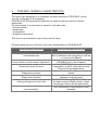
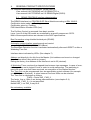
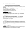
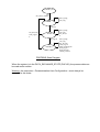
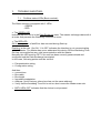
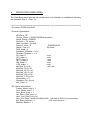
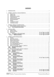
CONTENTS 1. INTRODUCTION:.....................................................................................................................2 2. PROFIBUS: GENERAL CHARACTERISTICS:....................................................................3 3. GENERAL PRODUCT SPECIFICATIONS...........................................................................4 3.1. REMIO PROFIBUS Interface characteristics:...............................................................4 4. INSTALLATION:........................................................................................................................5 4.1. Address setting:................................................................................................................5 4.2. Connections:......................................................................................................................6 4.2.1. Connections on basic module:...............................................................................6 4.2.1.1. Profibus connector:.............................................................................................6 5. PROFIBUS USER INFORMATION........................................................................................7 5.1. Principle: Data Transfer description / State Diagram................................................7 5.2. Slave diagnostic:...............................................................................................................9 5.2.1. Description of diag bytes in the first part of the diag field:..................................9 5.2.2. Description of diag bytes in the second part of the diag field: (user diag field): command word.......................................................................................................10 5.3. Configuration:..................................................................................................................11 5.4. Parametrisation:..............................................................................................................13 5.5. Global control:..................................................................................................................13 5.6. Access to the DI/DO ports and TPO channels:.........................................................14 5.6.1. Digital input/output (DI/DO) Ports:.........................................................................14 5.6.2. Time proportioning outputs (TPO):.......................................................................15 5.7. Other services:.................................................................................................................15 6. PERFORMANCES:................................................................................................................16 7. TROUBLE SHOOTING:.........................................................................................................17 7.1. Profibus status LEDs (basic module):.......................................................................17 7.2. Input / Output status LEDs:...........................................................................................18 7.2.1. Digital Input /Output modules (DI/DO modules):...............................................18 7.2.2. Time Proportioning Output module (TPO modules):........................................18 8. DEVICE DATA BASE (DDB):................................................................................................19 REMIO : PROFIBUS-DP Communications Interface Part N° HA 176078 ENG - Issue 2.0 - 07/2000 Communications Manual INTRODUCTION: 1. This manual describes Profibus communications implementation in REMIO/TPO and REMIO/Digital (DI/DO) TE series interfaces. Concerning any detail about these units or their functionnal operation, please refer to: - HA175874ENG iss.2 manual for REMIO/TPO interface - HA175726ENG iss.2.0 manual for REMIO/Digital (DI/DO) interface. Following documents have been used for these specifications: • Standard DIN 19245 / Part 1: PROFIBUS. - Data transmission technique, - Medium access methods and transmission protocols, - Service interface to the application layer, - Management. • Standard DIN 19245 / Part 3: PROFIBUS DP. - Process Fieldbus: Decentralised Periphery. • Standard ISO/IEC 8802-2: Information processing systems. - Logical Link Control. • Standard ISO/IEC 8802-4: Information processing systems. • Token passing bus access method and physical layer specifications. • Standard CEI 1131-3: programmable controllers programming Languages • Siemens SPC3 User Description. Version V1.0c - 12/1995. 2. PROFIBUS: GENERAL CHARACTERISTICS: The goal of this paragraph is to remember the basic principle of PROFIBUS, issued from the 1100 pages of the standard. PROFIBUS DP (Decentralised Peripherals) is made for the fast control of remote input/output. For this purpose, it is necessary to transmit in the same way: - Process values. - Parameters. - Configuration. - Diagnostics and faults. This kind of communication require fast reaction times. Following table gives an overview of the main characteristics of PROFIBUS DP. Requested characteristics Fast reaction time mono-master or multi-master Operations Simple and cheap Protocol Diagnostic functions Simple user Interface Existing Wiring and Tools Used Inter-operability PROFIBUS DP characteristics More than 1000 Input/Output Exchanges with 32 different units connected on the link in 10ms.(at 12 MBaud) Hybrid access to the medium following PROFIBUS part 1.specifications All the PROFIBUS functionalities are integrated in an ASIC which can be used alone for simple applications. Diagnostic function shared by masters and slaves. Basic set of parameters and configurations defined on the user level. PROFIBUS FMS and PROFIBUS DP share the same simple RS485 medium. Same technology used for all the applications. PNO certification of conformance to the standard. 3. GENERAL PRODUCT SPECIFICATIONS For complete specification information, please refer to: -User manual HA175874ENG iss.2.0 REMIO/TPO or -User manual HA175726ENG iss.2.0 REMIO/Digital (DI/DO). 3.1. REMIO PROFIBUS Interface characteristics: The REMIO Interface is a PROFIBUS-DP Slave Module according to DIN 19245-3. Certification tests made by: Pending Certification given by: Pending PNO Identification Number:1659 (hex) The Profibus Control is assumed from basic module. Layer 1 and 2 of the OSI model are controlled by a specific component: SPC3. Most of these specifications are relevant to the ASIC specifications. Bus Connection using shielded twisted pair (RS485). Automatic communication speed search and control 9.6/19.2/93.75/187.5/500/1500 KBaud. The BaudRate Detection function is activated automatically after each RESET or after a Watchdog Time Out. Interface status indicated by LEDs. (See chapter 7) Address set directly by the link from the Master (Unit address can be set or changed from the bus without any switch or jumper). Exiting the factory, the address of the interface is set to 32 (decimal). A Watchdog Timer monitors the elapsed time between two messages. In case of error, all the ports are set to logical 0 level in order to avoid malfunction. The watchdog is reset with each error free frame received, on recognition of the Station Number. The Time Out can be programmed from an appropriate control software (for example comET 200 from Siemens). A value between 2ms and 650s can be selected. The Time Out is calculated as follows: T(WD) = Factor*WD_1*WD_2 The factor 1ms or 10ms is set during parametrisation (see chapter 5.4). Setting WD_1*WD_2 =1 is not permitted. Neither WD_1 nor WD_2 may be 0. No redundancy available. 4. INSTALLATION: 4.1. Address setting: Before to start a DP system, it must be assigned an unmatched address to each station. For this purpose, the initial address (factory setting) is fixed at 32 (decimal). The slave address can ONLY BE SET BY THE LINK. This address is stored in a non-volatile memory and: • must be changed by the user before connecting the unit to the link. OR • The address setting must be made with only one slave at the address 32 at a time on the link. To be reminded: - address 127 reserved for broadcasting (defined in the standard). - address 125 reserved for remote configuration by Type 2 master for the first Start-up. Only addresses 0 to 124 can be used in normal operation with a type 1 Master (defined in the standard). Nota: As possible, do not use address 00 which is, generally, reserved for SIEMENS master. In the same way, addresses 0,1,2,3 are reserved for Simatic S7 from SIEMENS. 4.2. Connections: 4.2.1. Connections on basic module: 4.2.1.1. Profibus connector: The 6-pins connector on the bottom of the unit is used to connect the shielded twisted pair of the bus. RX-/TXRX+/TX+ 61 62 63 64 65 The connections number 61 and 65 are internally connected together, as well as the connections number 62 and 64. The communication electronics is insulated from the Control electronics. The earth terminal is accessible near the communication connector, at the bottom of the unit, for shielding purposes. Wiring and shielding information are given in the REMIO User Manuals (HA175874ENG for REMIO TPO and HA175726ENG for REMIO DI/DO). . It must be particularly paid attention to line impedance, to impedance adaptation of the link, maximal length, etc.... The bus terminal resistors can be put in or out circuit by means of the 2 switches intended for this purpose at the top of the unit. Note that only the last unit on the bus must have the Impedance adaptation resistors fit. SW1.3, SW1.4 bus termination resistors selection ON 1 2 3 4 More than 32 stations can not be used without any repeater. 5. PROFIBUS USER INFORMATION 5.1. Principle: Data Transfer description / State Diagram According to the standard DIN 19245-3, the Interface receive parametrisation data and configuration data. These 2 exchange types are required during the Start-up phase of the system. The device can reach the DATA_EXCHANGE STATE only when the 2 sequences: PARAMETRISATION and CONFIGURATION are completed. At Start-up, the device enters in a waiting phase. The STATE diagram is produced here after. (described in the standard DIN 19245-3). In this diagram, it will be found the following states: - POWER_ON: The system is powered. An Initialisation phase is started. Nota: Address change is supported on these units (SET_SLAVE_ADD supported). A Set_Slave_Address change is accepted only in the Power_On State. - WPRM = Wait_Parameters. The unit is waiting for System Parametrisation Message. ( PNO Identification, synchronisation and freeze mode acceptation,...) and for Data Parametrisation Message (which data are effectively available for read access). In this state , a Diagnostic demand is also accepted. Any other type of message is rejected in this State. - WCFG =Wait_Configuration. This kind of message specifies the number of data accessible to the input and output ports and possibilities of read and write for different parameters,.... In this State, the Unit is waiting for a Configuration message or Parametrisation message or Diagnostic message . Any other type of message is rejected in this State. - DXCHG = Data_Exchange. When the parametrisation and the configuration have been accepted, then the slave is ready for the Data Exchange with the Master which has parametrised and configured it, or with another master in the condition stated in the DP standard. POWER_ON init Set_Slave_Address Slave_Diag Get_Cfg WPRM Set_Prm,o k Set_Prm,nok Chk_Cfg,no k WCFG Chk_Cfg,ok DXCHG Slave_Diag Get_Cfg Set_Prm,o k Slave_Diag Get_Cfg Set_Prm,ok Chk_Cfg,ok Data_Exchange,ok Read_Input Read_Output Global_Control PROFIBUS State Diagram When the system is in the DATA_EXCHANGE_STATE (DXCHG), the process data can be read and/or written. Warning: the sequence « Parametrisation then Configuration » must always be executed in this order. 5.2. Slave diagnostic: The Diag can be read in any State of the State Machine. 5.2.1. Description of diag bytes in the first part of the diag field: This first six byte part of the Diag message is described in the chapter 8-3-1 of the Profibus DP standard MSB 7 • 6 LSB 5 4 3 2 1 0 BYTE 00: STATION STATUS 1 Bit 7: Master_Lock (Set by the DP Master). Bit 6: Prm_Fault Last Parameter Frame was faulty. Bit 5: Invalid Slave Response (Set by the DP Master). Bit 4: Not Supported Function requested not supported from this DP slave. Bit 3: Ext_Diag A Diag. Entry exists in the Slave specific Diag area (Ext_Diag_Data). Bit 2: Cfg Fault The last received configuration data from the DP-Master are different from these which the DP-Slave has determined ( see Check_Cfg ). Bit 1: Station Not Ready This Station is not yet ready for data transfer. Bit 0: Station Non Existent (Set by the DP Master). • BYTE 01: STATION STATUS 2 Bit 7: Deactivated (Set by the DP Master). Bit 6: (not used) Bit 5: Sync Mode This station has received the Sync control command. Bit 4: Freeze Mode This station has received the Freeze control command. Bit 3: WD On Set as soon as the WatchDog control has been activated. Bit 2:always set. Bit 1: Stat Diag Set as soon as an external communication fault has been detected ( in this case, the Diag LEDs. Indicate an external fault. See chap. 7 ). The DP-Master shall fetch diagnostic informations until this bit is reset again. Bit 0: Prm Req This station shall be re-parametrised and re-configured (This bit has priority on bit 1). • BYTE 02: STATION STATUS 3 Not used. • BYTE 03: MASTER ADD Address of the master which has parametrised this station. • BYTES 04/05: IDENT NUMBER PNO Ident number (2 octets). 5.2.2. Description of diag bytes in the second part of the diag field: (user diag field): command word The User Diag field begins at the address 6 of the Diag field. The unit sends diagnostics data to the master in this field. This field comprises 3 bytes. Diagnostic data are transferred only after a change of the pending data. One exception to this is the freeze mode. Important: if freeze mode is activated, the diagnostic data is also frozen. A frame is thus sent to the master with no change in diagnostic data until a further « freeze » command. • BYTE 06: Diag Header. This byte shows the total number of bytes in the external Diag Field comprising itself. This byte has always the value 03. • BYTE 07/08: Command Word. (CWh,CWl) Shows the actual configuration of the Unit as follows: Byte bit bit bit bit 7 6 5 4 07 0 0 0 08 0 0 0 bit 3 0= 0 SW1.1OFF 1= SW1.1 ON 0 0 bit 2 1 = second TPO optional module fit 0 bit 1 bit 0 Designation 1 = first 1 = TPO basic CWh TPO module (HIGH) optional 0 = DI/DO module basic module fit 0 = Input CWl 0 direct (LOW) 1= Input inverted 5.3. Configuration: The Configuration frame is provided by the Master indicating the configuration of the Input and Output Buffers. The unit expects 1,2,3 or 4 code bytes following the hardware configuration of the unit. These bytes are : • BYTE 1: = 0x35 indicating that the 6 ports of the unit are Read in the Input Buffer and Written in the Output Buffer. The 6 ports are read and written in the following order in both Input and Output Buffers. Offset 0 1 2 3 4 5 Port Port1 Port3 Port5 Port2 Port4 Port6 Direction OUTPUT OUTPUT OUTPUT INPUT / OUTPUT INPUT / OUTPUT INPUT / OUTPUT • BYTE 2: = none or 0x3F none if the unit is not TPO type. 3F if the unit is TPO type. The first 16 channels are read and written in the following order in both Input and Output Buffers. Offset 0 1 2 3 4 5 6 7 8 9 10 11 12 13 14 15 Channel 1 2 3 4 5 6 7 8 9 10 11 12 13 14 15 16 Direction OUTPUT OUTPUT OUTPUT OUTPUT OUTPUT OUTPUT OUTPUT OUTPUT OUTPUT OUTPUT OUTPUT OUTPUT OUTPUT OUTPUT OUTPUT OUTPUT • BYTE 3: = none or 0x3F none if less than 32 TPO output unit. 3F for at least 32 TPO output unit. The next 16 channels are read and written in the same order in both Input and Output Buffers • BYTE 4: = none or 0x3F none if less than 48 TPO output unit. 3F for 48 TPO output unit. The last 16 channels are read and written in the same order in both Input and Output Buffers 5.4. Parametrisation: The Master transfers parameter assignment data to the unit. 4 bytes of user parameter data must be sent to the unit in addition to the 7 normal parameter bytes. • BYTE 7: User_Def_PRM1 Byte 7 bit 7 bit 6 0 0 bit 5 0 bit 4 0 bit 3 0 bit 2 WD_Base Only Bit 2 defines the Watchdog time base 1L--->1ms bit 1 0 bit 0 0 designation User_Def_PRM1 0L--->10ms. • BYTES 8/9 : set to 0x00 • BYTE 10 : set to 0x00 or 0x01 (relevant of DI/DO products only) 0x00 ===> Bottom ports are read in direct logic. 0x01 ===> Bottom ports are read in inverted logic. Note: Bytes number 8 and 9 are used for production configuration purpose. 5.5. Global control: The unit supports SYNC and FREEZE modes. Note: if freeze mode is activated, the Diagnostic data is also frozen. A frame is thus sent to the master with no change in diagnostic data until a further « freeze » command. 5.6. Access to the DI/DO ports and TPO channels: The REMIO interface may contain up to 3 output ports, 3 Input/output ports (each being of eight bits)or 48 TPO channels. 5.6.1. Digital input/output (DI/DO) Ports: The 6 Ports are always present in the Input and Output buffer even if they are not used. (e.g. REMIO TPO interface). The 6 ports are read and written in the following order in both Input and Output Buffers. Absolute Address 0 1 2 3 4 5 Port Port1 Port3 Port5 Port2 Port4 Port6 If SW1.1 =ON: The 6 ports are configured as output and can be written in the Output Buffer. Note: attempting to write a TPO port has no effect. If SW1.1 =OFF: Output ports1,3,5 can be written in the Output Buffer at the addresses 0,1,2. Input ports 2,4,6 can be read in the Input Buffer at the addresses 3,4,5. Note: attempting to write an input port in the Output Buffer has no effect. Warning: The unit must be powered off in order to change SW1.1 position. Change of SW1.1 position during operation is not permitted. 5.6.2. Time proportioning outputs (TPO): The TPO channels are present in the Input and Output Buffer only if the unit is equipped with the corresponding modules. Basic module: absolute addresses 6 to 21. First optional module: absolute addresses 22 to 37. Second optional module: absolute addresses 38 to 53. 5.7. Other services: The unit supports following services: Set_Slave_Address Read_Inputs Read_Output Get_Config 6. PERFORMANCES: The system reaction time is described by the standard (see part 3 chap. 7 pages 3334). At 1.5Mbaud, following performances can be considered: One REMIO Interface unit can drive 32 TE units in less than 50µs. 32 REMIO Interface units can be accepted without repeater. Then up to 1000*TE units can be set ON or OFF in less than 2ms.(depending on the global configuration of the system). In any case, more than 1000 digital input thyristor units updated in less than 10ms at 1.5Mbaud. Example: On a full REMIO/TPO configuration the time measured for 108 variables exchanged (6 ports read and write and 48 TPO read and write) is 937 microseconds @ 1.5MBaud. 7. TROUBLE SHOOTING: 7.1. Profibus status LEDs (Basic module): The Basic module is equipped with 2 LEDs. - GREEN - RED • The GREEN LED indicates that the unit is in the Data Exchange state. The master exchanges data with it at a rate that prevents the Watchdog Time-Out to occur. • The RED LED ON in steady state: a fatal Error has occurred during Start-up. Flashing: at the rate 1.2s ON / 1.2s OFF indicates the Interface is not communicating with the Master. The Master has never addressed this device OR the Watchdog TimeOut has occurred before any valid communication with the Master. Normally this LED must be OFF if the unit has been correctly parametrised and configured and the Data Exchange has started. In this case, following points must be verified: ⇒ Parametrisation string. ⇒ Configuration string. And then: ⇒ connections ⇒ Bus cable ⇒ Bus length ⇒ Impedance adaptation ⇒ Address (Verify that any other slave has not the same address). ⇒ Verify that the watchdog Time-Out is not too short versus the Master scan rate. • BOTH LEDs OFF indicates that the device is not powered. 7.2. Input / Output status LEDs: 7.2.1. Digital Input /Output modules (DI/DO modules): Each module is equipped with 2 LEDs. - GREEN - ORANGE The GREEN LED indicates that all is in order with the corresponding module. (power supply and internal connections). The ORANGE LED is lit when the bi-directional Input /Output Ports at the bottom of the unit are configured as INPUT. 7.2.2. Time Proportioning Output module (TPO modules): The GREEN LED indicates that all is in order with the corresponding module. (power supply and internal connections). 8. DEVICE DATA BASE (DDB): The Data-Base which permits the configuration of the Master is established following the standard (Part 3 - chap. 13). ;++++++++++++++++++++++++++++++++++++++++++++++++++++++++++++++++++ ; File name: EURO1659.GSD ; General Informations: #Profibus_DP Vendor_Name = “EUROTHERM Automation” Model_Name = “REMIO” Revision = “TE series” Ident_Number = 0x1659 Protocol_Ident = 0 ; PROFIBUS DP Station_Type = 0 ; DP-slave FMS_supp = 0 Hardware_Release = “V1.0” Software_Release = “1.0” 9.6_supp = 1 ; auto 19.2_supp = 1 ; auto 93.75_supp = 1 ; auto 187.5_supp = 1 ; auto 500_supp = 1 ; auto 1.5M_supp = 1 ; auto MaxTsdr_9.6 = 60 ; unit = tbit MaxTsdr_19.2 = 60 MaxTsdr_93.75 = 60 MaxTsdr_187.5 = 60 MaxTsdr_500 = 100 MaxTsdr_1.5M = 150 Redundancy = 0 Repeater_Ctrl_Sig =0 24V_Pins = 0 ; DP_Slave Informations: Freeze_Mode_supp = 1 Sync_Mode_supp = 1 Auto_Baud_supp = 1 Set_Slave_Add_supp = 1 User_Prm_Data_Len =04 User_Prm_Data = 0x00,0x00,0x00,0x00 ;last byte to 0x01 for inverted logic Min_Slave_Intervall = 1 ; 100 micro-second Modular_Station = 1 Max_Module = 4 Max_Input_Len = 54 Max_output_Len = 54 Max_Data_Len = 108 Module = "REMIO BASE" 0x35 ;mandatory 1 module Endmodule Module = "REMIO TPO" 0x3f ;optional 0 to 3 modules Endmodule ;++++++++++++++++++++++++++++++++++++++++++++++++++++++++++++++++++