1
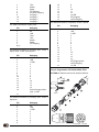
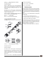
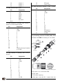
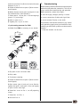
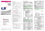
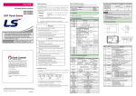
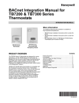
Benutzerinformation
MH../MV../SV..
Winkelkodierer
führen unverzüglich zum Verfall der Garantie:
• Zerlegen oder Öffnen des Gebers (soweit dies
nicht in dieser Benutzerinformation beschrieben
wird).
• Schläge auf das Gehäuse und die Welle beschädigen den Geber bzw. innere Teile und sind nicht
zulässig.
• Mechanische Bearbeitung der Welle, des Flansches oder Gehäuses (Bohren, Fräsen, usw.). Hierdurch kann es zu schweren Beschädigungen der
inneren Teile des Gebers kommen.
MH58
• Unzulässige axiale oder radiale Belastung der
Welle.
MV58
SV58
• Unsachgemäße Befestigung des Gebers.
Was Sie nicht tun sollten
DEUTSCH
1. Gewährleistungshinweise
• Lesen Sie vor der Montage und der Inbetriebnahme dieses Dokument sorgfältig durch. Beachten Sie
zu Ihrer eigenen Sicherheit und der Betriebssicherheit alle Warnungen und Hinweise.
• Ihr Produkt hat unser Werk in geprüftem und
betriebsbereitem Zustand verlassen. Für den Betrieb gelten die angegeben Spezifikationen und die
Angaben auf dem Typenschild als Bedingung.
• Garantieansprüche gelten nur für Produkte der
Firma SIKO GmbH. Bei dem Einsatz in Verbindung
mit Fremdprodukten besteht für das Gesamtsystem
kein Garantieanspruch.
4. Mechanische Montage
• Reparaturen dürfen nur im Werk vorgenommen
werden. Für weitere Fragen steht Ihnen die Firma
SIKO GmbH gerne zur Verfügung.
Die Montage darf nur gemäß der angegebenen IPSchutzart vorgenommen werden. Das System muss
ggfs. zusätzlich gegen schädliche Umwelteinflüsse,
wie z.B. Spritzwasser, Staub, Schläge, Temperatur
geschützt werden.
2. Identifikation
Anbau des Gebers
Das Typenschild zeigt den Gerätetyp mit Variantennummer. Die Lieferpapiere ordnen jeder Variantennummer eine detaillierte Bestellbezeichnung zu.
z.B.
MV58-0023
Varianten-Nr.
Geräte-Typ
3. Garantiehinweise
Gehen Sie sorgfältig mit dem Geber um. Es handelt
sich um ein Präzisionsmessgerät. Folgende Punkte
MH../MV../SV..
Datum 24.03.2005
• Bei Vollwellengebern erfolgt die Befestigung durch
Gewindebohrungen an der Stirnfläche des Gebers
oder durch Klemmung am Flansch. Die mechanische
Verbindung der Antriebswelle erfolgt am besten mit
einer Ausgleichskupplung (z.B. AK18).
• Bei Hohlwellengebern erfolgt die Befestigung
vorzugsweise über eine Drehmomentabstützung, die
es ermöglicht, geringe Fertigungstoleranzen auszugleichen. Montieren Sie den Geber auf jeden Fall
verspannungsfrei.
Art.Nr. 81286
Änd.Stand 106/05
1
• Kräfte dürfen nicht durch das Gehäuse übertragen werden. Sie dürfen ausschließlich an der Welle
des Geräts wirken.
6. Elektrischer Anschluss
• Beachten Sie die maximalen axialen und radialen
Wellenbelastungen.
• Achten Sie auf geringen Wellen- und Winkelversatz. Bei nicht korrekter axialer oder winkliger
Stellung zwischen Welle und Flansch entstehen
Spannungen im Lager, die über erhöhte Erwärmung
bis zur Zerstörung der Lager führen können.
• Wenn durch den Ausfall oder eine Fehlfunktion
des Gebers eine Gefährdung von Mensch oder eine
Beschädigung von Betriebseinrichtungen nicht
auszuschließen ist, so muss dies durch geeignete
Sicherheitsmaßnahmen wie Schutzvorrichtungen
oder Endschalter usw. verhindert werden, bzw.
muss das Gerät außer Betrieb gesetzt und gegen
unbeabsichtigtes Einschalten gesichert werden.
5. Funktionen
Erforderliche Maßnahmen:
Vor/Rück-Eingang zur Zählrichtungsumschaltung
(nur für MH58, MV58) :
Standardmäßig geben die absoluten Drehgeber bei
Drehung der Welle im Uhrzeigersinn (cw) mit Blick
auf die Welle aufsteigende Kodewerte aus. Bei
drehung im Gegenuhrzeigersinn (ccw) stehen entspr. fallende Kodewerte am Ausgang an. Solange ein
entsprechendes Signal (high) am V/R-Eingang ansteht, wird diese Charakteristik umgedreht. Bei
Drehung der Welle im Uhrzeigersinn werden fallende
Kodewerte, bei Drehung der Welle im Gegenuhrzeigersinn steigende Kodewerte ausgegeben.
Sicherheitshinweise :
• Anschlussverbindungen dürfen nicht unter
Spannung geschlossen oder gelöst werden!!
• Litzen sind mit Aderendhülsen zu versehen.
• Nur geschirmtes Kabel verwenden. Den Kabelschirm beidseitig auflegen. Litzenquerschnitt der
Leitungen min. 0,14 mm2, max. 0,5 mm2. Alle nicht
benötigten Enden sauber isolieren, um Kurzschlüsse zu vermeiden.
• Die Verdrahtung von Abschirmung und Masse
(0V) muss sternförmig und großflächig erfolgen. Der
Anschluss der Abschirmung an den Potentialausgleich muss großflächig (niederimpedant) erfolgen.
Die Ansprechzeit beträgt:
- bei 5-30VDC Versorgungsspannung 10ms
• Vor dem Einschalten sind alle Leitungsanschlüsse
und Steckverbindungen zu überprüfen.
SET-Eingang :
• Um CE-Konformität zu erreichen, ist eine EMVgerechte Installation Vorraussetzung.
Dieser Eingang dient zur Justage (Nullung) des
Drehgebers. Durch einen entsprechenden Steuerimpuls (high) auf diesen Eingang kann der aktuelle
Positionswert als neue 0-Position im Drehgeber
gespeichert werden.
• Bei Problemen durch Erdschleifen ist die Schutzerde (PE) auf der Geberseite aufzutrennen. Der
Geber sollte hierbei gegenüber dem Antrieb elektrisch isoliert angebaut werden.
Anmerkung: Vor dem Aktivieren des SET-Eingangs,
nach dem Anlegen der Versorgungsspannung an den
Geber, muss mit dem V/R-Eingang eindeutig eine
Zählrichtung (cw oder ccw) vorgegeben sein!
Die Ansprechzeit beträgt:
- bei 5-30VDC Versorgungsspannung 10ms (MH/MV58);
- bei 10-30VDC Versorgungsspannung 2ms (SV58).
LATCH-Eingang (nur bei SV58) :
Dieser Eingang dient dazu, den aktuellen Positionswert "einzufrieren". Solange dieser Eingang aktiv
(high) ist, steht der Positionswert am Parallelausgang statisch an.
Die Ansprechzeit beträgt:
- bei 10-30VDC Versorgungsspannung 200µs.
2
MH../MV../SV..
Datum 24.03.2005
Hinweise zur Störsicherheit
• Alle Anschlüsse sind gegen äußere Störeinflüsse
geschützt. Der Einsatzort ist aber so zu wählen,
dass induktive oder kapazitive Störungen nicht
auf den Geber oder deren Anschlussleitungen
einwirken können! Durch geeignete Kabelführung
und Verdrahtung können Störeinflüsse (z.B. von
Schaltnetzteilen, Motoren, getakteten Reglern oder
Schützen) vermindert werden.
• Das System muss in möglichst großem Abstand
von Leitungen eingebaut werden, die mit Störungen belastet sind; ggfs. sind zusätzliche Maßnahmen wie Schirmbleche oder metallisierte Gehäuse vorzusehen. Leitungsführungen parallel zu Energieleitungen vermeiden.
• Schützspulen müssen mit Funkenlöschgliedern
beschaltet sein.
Art.Nr. 81286
Änd.Stand 106/05
Spannungsversorgung
Die Spannungswerte sind abhängig von der Geräteausführung und sind den Lieferpapieren und dem
Typenschild zu entnehmen.
z.B.
5...30 VDC (MH58, MV58)
10...30 VDC (SV58)
braungrün
weißgelb
gelbbraun
12
13
Drehrichtungsumkehr
oder 14 LSB
Für SV58 Schnittstelle P1 (Parallel); max. 13 Bit, 2
Optionen.
6.1 Anschlussart E1
Farbe
Belegung
Für MV58, MH58.
weiß
braun
grün
gelb
grau
rosa
blau
rot
schwarz
violett
graurosa
rotblau
weißgrün
braungrün
weißgelb
gelbbraun
weißgrau
0V
+UB
1 MSB
2
3
4
5
6
7
8
9
10
11
12
13 LSB
SET-Eingang
LATCH-Eingang
Farbe
Belegung
weiß
braun
grün
gelb
grau
rosa
blau
rot
schwarz
violett
graurosa
rotblau
0V
+UB
Takt+
TaktDaten+
DatenSET-Eingang
Vor/Rück-Eingang
Ausgang 1
Ausgang 2
Ausgang 3
Ausgang 4
Für SV58 Schnittstelle S6/04 (SSI).
Farbe
Belegung
weiß
braun
grün
gelb
grau
rosa
blau
rot
schwarz
violett
graurosa
rotblau
0V
+UB
Takt+
TaktDaten+
DatenSET-Eingang
-----------
Für SV58 Schnittstelle P1 (Parallel); max. 13 Bit +
1 Option oder 14 Bit ohne Option.
Farbe
Belegung
weiß
braun
grün
gelb
grau
rosa
blau
rot
schwarz
violett
graurosa
rotblau
weißgrün
0V
+UB
1 MSB
2
3
4
5
6
7
8
9
10
11
MH../MV../SV..
Datum 24.03.2005
Für SV58 Schnittstelle P1 (Parallel); 14 Bit, 2
Optionen.
Farbe
Belegung
weiß
braun
grün
gelb
grau
rosa
blau
rot
schwarz
violett
graurosa
rotblau
weißgrün
braungrün
weißgelb
gelbbraun
weißgrau
graubraun
0V
+UB
1 MSB
2
3
4
5
6
7
8
9
10
11
12
13
SET-Eingang
LATCH-Eingang
14 LSB
6.2 Anschlussart E2
Für MV58, MH58.
Pin
Belegung
1
2
3
0V
+UB
Takt+
Art.Nr. 81286
Änd.Stand 106/05
3
4
5
6
7
8
9
10
11
12
TaktDaten+
DatenSET-Eingang
Vor/Rück-Eingang
Ausgang 1
Ausgang 2
Ausgang 3
Ausgang 4
Für SV58 Schnittstelle S6/04 (SSI).
Pin
Belegung
1
2
3
4
5
6
7
8-12
0V
+UB
Takt+
TaktDaten+
DatenSET-Eingang
---
Für SV58 Schnittstelle P1 (Parallel); max. 13 Bit, 1
Option oder 14 Bit ohne Option..
Pin
Belegung
1
2
3
4
5
6
7
8
9
10
11
12
13
14
15
16
0V
+UB
1 MSB
2
3
4
5
6
7
8
9
10
11
12
13
Drehrichtungsumkehr
oder 14 LSB
---
17
10
11
12
13
14
15
16
17
8
9
10
11
12
13 LSB
SET-Eingang
LATCH-Eingang
Für SV58 Schnittstelle P1 (Parallel); 14 Bit, 1 Option.
Pin
Belegung
1
2
3
4
5
6
7
8
9
10
11
12
13
14
15
16
0V
+UB
1 MSB
2
3
4
5
6
7
8
9
10
11
12
13
SET-Eingang oder
LATCH-Eingang
14 LSB
17
12-pol. Gegenstecker für MV58, MH58, SV58
Bei SIKO als Zubehör unter Art.Nr. 81935 erhältlich.
Schirm
Für SV58 Schnittstelle P1 (Parallel); max. 13 Bit, 2
Optionen.
4
Pin
Belegung
1
2
3
4
5
6
7
8
9
0V
+UB
1 MSB
2
3
4
5
6
7
MH../MV../SV..
Ansichtseite = Lötseite
Datum 24.03.2005
Art.Nr. 81286
Änd.Stand 106/05
1. Pos. 1 ... 3 über Kabelmantel schieben.
der Schirm abschneiden.
2. Kabel abisolieren.
7. Pos. 5 in Pos. 1 einschieben.
3. Schirm umlegen.
4. Pos. 4 über die Folie bzw. Baumwollgeflecht,
jedoch unter das Schirmgeflecht schieben. Schirmgeflecht bündig mit Außendurchmesser Pos. 4 abschneiden.
5. Litzen an Pos. 6 löten (entspr. Anschlussplan).
6. Distanzhülse Pos. 5 aufweiten und über Litzen
stülpen, zusammendrücken.
7. Pos. 5+6 in Pos. 7 einführen. Schlitz und Nut von
Pos. 6+7 müssen deckungsgleich sein.
8. Pos. 2 ... 4 aufschieben.
9. Pos. 1 auf Anschlag festschrauben.
8. Pos. 6 aufschrauben.
7. Inbetriebnahme
Bitte beachten Sie die Hinweise auf ordnungsgemäßen mechanischen und elektrischen Anschluss. Nur
dann sind die Voraussetzungen für eine problemlose Inbetriebnahme und einwandfreien Betrieb gegeben.
Prüfen Sie vor der Inbetriebnahme insbesondere
nochmals auf:
• korrekte Polung der Betriebsspannung.
• korrekten Anschluss des Kabels und der Signale.
• festen Sitz des Gebers und der Welle.
17-pol. Gegenstecker für SV58
Bei SIKO als Zubehör unter Art.Nr. 81294 erhältlich.
Die Betriebsspannung des Gebers muss gemeinsam
mit der der Folgeelektronik (z.B. Steuerung) eingeschaltet werden, um Latchup-Effekte an den Ausgängen des Gebers zu vermeiden.
--> Nehmen Sie den Geber elektrisch in Betrieb.
Schirm
Schirm
Ansichtseite = Lötseite
1. Pos. 4 ... 6 über Kabelmantel schieben.
2. Kabel abisolieren.
3. Schirm umlegen.
4. Litzen an Pos. 2 löten (entspr. Anschlussplan).
5. Abstandhülse Pos. 3 aufweiten und über Litzen
stülpen, zusammendrücken und auf Pos. 2 stecken.
Schlitz und Nut (Pos. 2 und 3) müssen deckungsgleich sein.
6. Pos. 2+3+4 in Pos. 1 einschieben, überstehenMH../MV../SV..
Datum 24.03.2005
Art.Nr. 81286
Änd.Stand 106/05
5
6
MH../MV../SV..
Datum 24.03.2005
Art.Nr. 81286
Änd.Stand 106/05
User Information
MH../MV../SV..
Absolute Encoder
precision device.
Especially do not:
• disassemble or open the encoder (unless stipulated in this brochure).
• knock the housing and the shaft, because this
will damage the encoder or internal parts.
• machine (bore, mill ...) flange or shaft. This
could lead to severe damage inside the encoder.
MH58
• exceed the values for the maximum axial and
radial shaft load.
• mount the encoder incorrectly.
MV58
SV58
Otherwise manufacturer's warranty will be invalidated!
NEVER ...
ENGLISH
1. Warranty information
• In order to carry out installation correctly, we
strongly recommend this document is read very
carefully. This will ensure your own safety and the
operating reliability of the device.
• Your device has been quality controlled, tested
and is ready for use. Please observe all warnings and
information which are marked either directly on the
device or specified in this document.
• Warranty can only be claimed for components
supplied by SIKO GmbH. If the system is used
together with other products, there is no warranty
for the complete system.
• Repairs should be carried out only at our works.
If any information is missing or unclear, please
contact the SIKO sales staff.
2. Identification
Please check the particular type of unit and type
number from the identification plate. Type number
and the corresponding version are indicated in the
delivery documentation.
e.g.
MV58-0023
version number
type of unit
4. Installation
For mounting, the degree of protection specified
must be observed. If necessary, protect the unit
against environmental influences such as sprayed
water, dust, knocks, extreme temperatures.
Mounting of the encoder
• In the case of solid shaft encoders fastening is
done by tapped holes on the encoder or by clamping on the flange. For linking solid shaft and
driving shaft, a flexible shaft coupling should be
used (e.g. AK18).
• In the case of hollow shaft encoders fastening is
preferably done via a torque brace, which enables
compensation of minor production tolerances.
Ensure that the encoder is mounted without strain.
3. Warranty information
• Forces must not be transmitted via the housing,
but only via the shaft.
Please handle the encoder carefully as it is a high-
• Do not exceed the values for the maximum axial
MH../MV../SV..
Datum 24.03.2005
Art.Nr. 81286
Änd.Stand 106/05
7
and radial shaft load.
• Ensure accurate shaft alignment. If shaft and
flange are not correctly aligned, strain on the
bearings will result, which will overheat and be
irreparably damaged.
5. Functions
the device must be disabled and secured against
accidental switching on.
Necessary measures:
• Switch power off before any plug is inserted
or removed!!
• Provide stranded wires with ferrules.
Forward/backward input for count direction
switch-over (only for MH58, MV58) :
By default, absolute rotary encoders output ascending code values when the shaft rotates clockwise
(cw) as you look on the shaft. Ac-cordingly, descending code values come up on the output with
counter-clockwise (ccw) rotation. This characteristic is reversed as long as a corresponding signal
(high) is on the F/B input. Descending code values
are output with clockwise shaft rotation, and
ascending code values are output with counterclockwise rotation.
The response time is:
- 10ms with 5-30VDC supply voltage
SET input :
This input serves for adjustment (zeroing) of the
rotary encoder. By means of a corresponding trigger
pulse (high) on this input, the current position
value can be saved as the new 0 position of the
rotary encoder.
Note: Prior to activating the SET input, after
switching on the power supply to the encoder, the
counting direction (cw or ccw) must be definitely
specified with the F/B input!
The response time is:
- 10ms with 5-30VDC supply voltage (MH/MV58);
- 2 ms with 10-30VDC supply voltage (SV58).
LATCH input (only with SV58) :
This input serves for "freezing in" the current
position value. The position value on the parallel
output is static as long as this input is active
(high).
The response time is:
- 200µs with 10-30VDC supply voltage.
6. Electrical connection
• Only screened cable should be used. Wire cross
section is to be at least 0,14 mm2, max. 0,5 mm2.
To prevent short-circuits, neatly insulate the end
of all strands which are not required.
• Wiring to screen and to ground (0V) must be via
a good earth point having a large surface area for
minimum impedance.
• Check all lines and connections before switching
on the equipment.
• In order to obtain CE-Conformity, EMC installation conformity should be observed.
• In case of earth loop problems, the protection
earth of the encoder side has to be removed. On this
occasion, the encoder should be placed electrically
isolated opposite the actuation.
Interference and distortion
• All connections are protected against the effects
of interference. The location should be selected
to ensure that no capacitive or inductive interferences can affect the encoder or the connection lines! Suitable wiring layout and choice of
cable can minimise the effects of interference (eg.
interference caused by SMPS, motors, cyclic controls and contactors).
• The unit should be positioned well away from
cables with interference; if necessary a protective
screen or metal housing must be provided. The
running of wiring parallel to the mains supply
should be avoided.
• Contactor coils must be linked with spark suppression.
Power supply
Operating voltage depends on execution and is
indicated in the delivery documentation or on the
identification plate.
e.g.
Safety precautions :
5...30 VDC (MH58, MV58)
10...30 VDC (SV58)
• If personal injury or damage to equipment is
possible should the encoder fail or malfunction, this
must be prevented by suitable safety precautions
such as protective devices or limit switches, etc., or
8
MH../MV../SV..
Datum 24.03.2005
Art.Nr. 81286
Änd.Stand 106/05
6.1 Connection type E1
For SV58 interface P1 (Parallel); max. 13 Bit, 2
options.
For MV58, MH58.
Color
white
brown
green
yellow
grey
pink
blue
red
black
violet
greypink
redblue
Designation
Color
Designation
0V
+UB
Cycle+
CycleData+
DataSET input
forward/backward input
output 1
output 2
output 3
output 4
white
brown
green
yellow
grey
pink
blue
red
black
violet
greypink
redblue
whitegreen
browngreen
whiteyellow
yellowbrown
whitegrey
0V
+UB
1 MSB
2
3
4
5
6
7
8
9
10
11
12
13 LSB
SET input
LATCH input
For SV58 interface S6/04 (SSI).
Color
Designation
white
brown
green
yellow
grey
pink
blue
red
black
violet
greypink
redblue
0V
+UB
Cycle+
CycleData+
DataSET input
-----------
For SV58 interface P1 (Parallel); max. 13 Bit + 1
option or 14 Bit without option.
Color
Designation
white
brown
green
yellow
grey
pink
blue
red
black
violet
greypink
redblue
whitegreen
browngreen
whiteyellow
yellowbrown
0V
+UB
1 MSB
2
3
4
5
6
7
8
9
10
11
12
13
reversion of sense of rotation
or 14 LSB
MH../MV../SV..
Datum 24.03.2005
For SV58 interface P1 (Parallel); 14 Bit, 2 options.
Color
Designation
white
brown
green
yellow
grey
pink
blue
red
black
violet
greypink
redblue
whitegreen
browngreen
whiteyellow
yellowbrown
whitegrey
greybrown
0V
+UB
1 MSB
2
3
4
5
6
7
8
9
10
11
12
13
SET input
LATCH input
14 LSB
6.2 Connection type E2
For MV58, MH58.
Pin
Designation
1
2
3
4
5
6
7
8
9
0V
+UB
Cycle+
CycleData+
DataSET input
forward/backward input
output 1
Art.Nr. 81286
Änd.Stand 106/05
9
10
11
12
output 2
output 3
output 4
For SV58 interface S6/04 (SSI).
Pin
Designation
1
2
3
4
5
6
7
8-12
0V
+UB
Cycle+
CycleData+
DataSET input
---
For SV58 interface P1 (Parallel); max. 13 Bit + 1
option or 14 Bit without option.
Pin
Designation
1
2
3
4
5
6
7
8
9
10
11
12
13
14
15
16
0V
+UB
1 MSB
2
3
4
5
6
7
8
9
10
11
12
13
reversion of sense of rotation
or 14 LSB
---
17
16
17
SET input
LATCH input
For SV58 interface P1 (Parallel); 14 Bit, 1 option.
Pin
Designation
1
2
3
4
5
6
7
8
9
10
11
12
13
14
15
16
0V
+UB
1 MSB
2
3
4
5
6
7
8
9
10
11
12
13
SET input or
LATCH input
14 LSB
17
12-pole mating connector for MV58, MH58, SV58
Available from SIKO as accessory art. no. 81935.
screening
For SV58 interface P1 (Parallel); max. 13 Bit, 2
options.
10
Pin
Designation
1
2
3
4
5
6
7
8
9
10
11
12
13
14
15
0V
+UB
1 MSB
2
3
4
5
6
7
8
9
10
11
12
13 LSB
MH../MV../SV..
viewing side = soldering side
1. Slip parts 1 to 3 over outer cable.
2. Strip cable.
3. Turn down screening.
4. Slide part 4 over the foil / cotton cloth, but
Datum 24.03.2005
Art.Nr. 81286
Änd.Stand 106/05
under the wire cloth. Cut flush wire cloth with outer
diameter of pos. 4.
7. Commissioning
5. Solder stranded wires at part 6 (follow connection diagram).
Please carefully read the information on the encoder's
mechanical and electrical connection. This will ensure a trouble free commissioning and operation.
6. Widen distance sleeve (part 5) and push it over
the stranded wires; then squeeze it.
Before operation, please check again:
7. Insert parts 5 + 6 into part 7. Slot and keyways
(parts 6 + 7) must align.
• correct connection of cable and signal lines
8. Slide on parts 2 to 4.
• that the supply voltage's polarity is correct.
• secure encoder fixation on the shaft.
9. Tighten part 1 up to its limit.
17-pole mating connector for SV58
Available from SIKO as accessory art. no. 81294.
The encoder's and follower electronic's (eg. control
unit) operating supply must be switched on simultaneoulsy to avoid latch-up effects on the encoder's
outputs.
--> Now the encoder can be used.
screening
screening
viewing side = soldering side
1. Slip parts 4 to 6 over outer cable.
2. Strip cable.
3. Turn down screening.
4. Solder stranded wires at part 2 (follow connection diagram).
5. Open spacer (part 3) and put it over ferrules,
squeeze and push it onto part 2. Slot and keyway
of parts 2 and 3 must align.
6. Insert Pos. 2+3+4 in Pos. 1, cut off projecting
screen.
7. Insert Pos. 5 in Pos. 1.
8. Screw on Pos. 6.
MH../MV../SV..
Datum 24.03.2005
Art.Nr. 81286
Änd.Stand 106/05
11
SIKO GmbH
Werk / Factory:
Weihermattenweg 2
79256 Buchenbach-Unteribental
Postanschrift / Postal address:
Postfach 1106
79195 Kirchzarten
Telefon / Phone
Telefax / Fax
eMail
Internet
12
MH../MV../SV..
Datum 24.03.2005
Art.Nr. 81286
+49 07661 394-0
+49 07661 394-388
[email protected]
www.siko.de
Änd.Stand 106/05