1
OPM01PI021
April 2001
3SPACE®
ISOTRAK II®
USER'S MANUAL
2001 Edition, Rev. A
OPM01PI021
April 2001
Copyright © 2000 by Polhemus Incorporated
Colchester, Vermont U.S.A.
All rights reserved. No part of this publication may be reproduced, stored in a retrieval system, or
transmitted, in any form or by any means, mechanical, photocopying, recording or otherwise,
without the prior written permission of Polhemus Incorporated. No patent liability is assumed
with respect to the use of the information contained herein. While every precaution has been taken
in the preparation of this book, Polhemus Incorporated assumes no responsibility for errors or
omissions. Neither is any liability assumed for damages resulting from use of the information
contained herein.
3SPACE® and ISOTRAK II® are registered trademarks of Polhemus Incorporated.
FCC Statement
This equipment has been tested and found to comply with the limits for a Class A digital device,
pursuant to part 15 of the FCC Rules. These limits are designed to provide reasonable protection
against interference when the equipment is operated in a commercial environment. This
equipment generates, uses, and can radiate radio frequency energy and, if not installed and used in
accordance with the instruction manual, may cause interference to radio communications.
Operation of this equipment in a residential area is likely to cause interference in which case the
user will be required to correct the interference at his own expense.
EC-Declaration of Incorporation
This product conforms to the following European Community Directives:
89/336/EEC AS AMENDED BY 92/31/EEC, 73/23/EEC LOW VOLTAGE AS AMENDED
BY 93/68/EEC
The following standards were used to verify compliance with the Directives:
EN50081-2, EN50082-1, EN60950, *EN55022
* NOTE: This product complies with the Class A requirements of EN55022.
OPM01PI021
April 2001
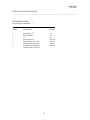
Table of Contents
1.0 GETTING STARTED ...............................................................................................................................1
COMPLETE ISOTRAK II SYSTEM ..................................................................................................................1
TRANSMITTER CONNECTION ...........................................................................................................................2
RECEIVER CONNECTION .................................................................................................................................2
MOUNTING TRANSMITTER AND RECEIVER ON 2X4 .........................................................................................3
POWER CONNECTOR .......................................................................................................................................3
DC POWER CABLE INSERTION ........................................................................................................................4
DEFAULT I/O SELECT DIP SWITCH SETTINGS ..................................................................................................5
RS-232 CABLE CONNECTION..........................................................................................................................5
ISOTRAK II DATA RECORD ..........................................................................................................................6
CONTACTING POLHEMUS CUSTOMER SERVICE ..............................................................................8
ISOTRAK II COMMANDS INDEX ..............................................................................................................9
2.0 TECHNICAL OVERVIEW ....................................................................................................................10
3.0 SPECIFICATION ....................................................................................................................................11
POSITION COVERAGE ....................................................................................................................................11
ANGULAR COVERAGE ...................................................................................................................................11
STATIC ACCURACY .......................................................................................................................................11
RESOLUTION .................................................................................................................................................11
LATENCY ......................................................................................................................................................11
OUTPUT ........................................................................................................................................................11
UPDATE RATE ...............................................................................................................................................11
CARRIER FREQUENCY ...................................................................................................................................12
INTERFACE....................................................................................................................................................12
OPERATING ENVIRONMENT ..........................................................................................................................12
OPERATING TEMPERATURE ..........................................................................................................................12
PHYSICAL CHARACTERISTICS........................................................................................................................12
POWER REQUIREMENTS ................................................................................................................................13
4.0 COMPONENT DESCRIPTION .............................................................................................................14
4.1 SEU .......................................................................................................................................................14
4.2 TRANSMITTER PORT ..............................................................................................................................16
4.3 RECEIVER PORTS (2)..............................................................................................................................16
4.4 POWER INDICATOR ................................................................................................................................16
4.5 I/O SELECT SWITCH ...............................................................................................................................16
4.6 EXTERNAL SYNC I/O .............................................................................................................................18
4.7 RS-232 I/O ............................................................................................................................................18
4.8 POWER INPUT RECEPTACLE ....................................................................................................................19
4.9 TRANSMITTER........................................................................................................................................19
4.10 RECEIVER(S) ........................................................................................................................................21
4.11 STYLUS ................................................................................................................................................21
4.12 3BALL ................................................................................................................................................21
4.20 MINI RECEIVER ....................................................................................................................................25
OPM01PI021
April 2001
5.0 SYSTEM OPERATION ..........................................................................................................................26
5.1 I/O CONSIDERATIONS .............................................................................................................................26
RS-232 CABLE CONNECTIONS ......................................................................................................................26
5.2 POWERING UP ISOTRAK II ..................................................................................................................26
5.3 CONFIGURATION CHANGES ....................................................................................................................27
5.4 SYNCHRONIZATION ................................................................................................................................27
5.5 INTERNAL SYNC.....................................................................................................................................28
5.6 EXTERNAL SYNC ...................................................................................................................................28
5.7 MULTIPLE SYSTEMS SYNCHRONIZATION ...............................................................................................28
5.8 OUTPUT CONSIDERATIONS .....................................................................................................................29
6.0 SYSTEM COMMANDS .........................................................................................................................32
6.1 COMMAND FORMAT NOTATION AND CONVENTION ...............................................................................32
6.2 COMMAND FORMAT NOTES ...................................................................................................................33
6.3 COMMAND/OUTPUT LISTING .................................................................................................................33
ALIGNMENT REFERENCE FRAME A .................................................................................................34
RESET ALIGNMENT REFERENCE FRAME R ....................................................................................37
BORESIGHT
B ....................................................................................................................................38
B .................................................................................................................................39
UNBORESIGHT
CONTINUOUS PRINT OUTPUT C .......................................................................................................40
DISABLE CONTINUOUS PRINTING C.................................................................................................41
ENABLE DIGITIZER MODE Y ............................................................................................................42
ENABLE “RUN” DIGITIZER MODE E .................................................................................................43
ENABLE “POINT” DIGITIZER MODE E ..............................................................................................44
SET TRACK DIGITIZER MODE I ........................................................................................................45
ENABLE ASCII OUTPUT FORMAT F .................................................................................................46
ENABLE BINARY OUTPUT FORMAT F ..............................................................................................47
HEMISPHERE OF OPERATION H .......................................................................................................48
DEFINE INCREMENT I ........................................................................................................................51
12 .................................................................................................................................................................52
ENABLE QUIET MODE K ....................................................................................................................53
THE SYSTEM WILL NOW BE IN “QUIET MODE.”...............................................................................................53
DISABLE QUIET MODE M...................................................................................................................56
DEFINE TIP OFFSETS N ......................................................................................................................57
OUTPUT DATA LIST O ........................................................................................................................58
1
OUTPUT ITEM N A2..........................................................................................................................59
CARRIAGE RETURN, LINE FEED A2 .....................................................................................................59
2
SYSTEM DATA RECORD, ASCII FORMAT ...........................................................................................60
SYSTEM DATA RECORD, BINARY FORMAT ......................................................................................61
SINGLE DATA RECORD OUTPUT P ...................................................................................................62
SYSTEM STATUS RECORD S .............................................................................................................64
ENGLISH CONVERSION UNITS U ......................................................................................................69
METRIC CONVERSION UNITS U ........................................................................................................70
POSITION OPERATIONAL ENVELOPE V...........................................................................................71
ATTITUDE FILTER PARAMETERS V ..................................................................................................73
POSITION FILTER PARAMETERS X ...................................................................................................76
REINITIALIZE SYSTEM CTRL Y .........................................................................................................79
COMPATIBILITY MODE CTRL D ........................................................................................................80
END TRACK MODE CTRL E .................................................................................................................81
SUSPEND DATA TRANSMISSION CTRL S .........................................................................................82
RESUME DATA TRANSMISSION CTRL Q ..........................................................................................83
6.4 ERROR CODES AND TROUBLE SHOOTING...............................................................................................84
7.0 LIMITED WARRANTY AND LIMITATION OF LIABILITY .........................................................85
OPM01PI021
April 2001
8.0 INDEMNITY AGAINST PATENT INFRINGEMENT........................................................................87
GLOSSARY ....................................................................................................................................................89
APPENDIX A: STANDARD/OPTIONAL ITEMS .......................................................................................
APPENDIX B: ‘ACCURACY AND RESOLUTION’ WHITE PAPER ......................................................
APPENDIX C: ‘LATENCY’ WHITE PAPER ..............................................................................................
APPENDIX D: CABLE DIAGRAMS ............................................................................................................
INDEX .................................................................................................................................................................
OPM01PI021
April 2001
1.0 Getting Started
Congratulations on buying the finest low-cost 3D tracker system available! This section of the
user manual has been provided to help get your project under way as quickly as possible.
There are two ways to get started with your ISOTRAK II system, as with any new system. You
could "wing it," which involves a great deal of assumptions based on either previous experience
and/or visual inspection, and hope for the best. Alternatively, you could sit down and read the
whole manual, line-by-line, and then start. What we provide here is a middle ground to cover the
basics to get you going quickly. However, this approach does not preclude using the manual as a
precise guide, reference and final arbiter.
NOTE: This approach assumes a single receiver, use of the RS-232 serial port at 9600 Baud
communicating with a Windows 95/98/NT PC, and use of the Microsoft Windows program
HYPERTERMINAL.EXE.
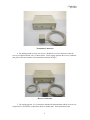
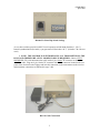
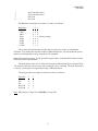
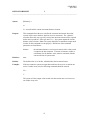
1. Unpack the ISOTRAK II SEU, transmitter, receiver(s), and power supply.
Complete ISOTRAK II System
2. Set up the system close to your host computer and away from large metal objects like file
cabinets, metal desks, etc. and away from the floor and walls.
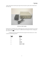
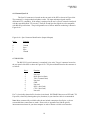
3. Identify the transmitter (the two-inch gray cube) and insert the transmitter connector into
the transmitter receptacle, being careful to firmly engage it. Using your fingers or a small, flat
blade screwdriver, lock the connector by tightening the two retaining screws.
1
OPM01PI021
April 2001
Transmitter Connection
4. For getting started, use only one receiver. Identify the receiver and insert it into the
receiver receptacle labeled “one” as shown below. Firmly engage and lock the receiver connector
into place in the same manner as the transmitter connector in Step 3.
Receiver Connection
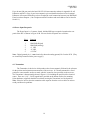
5. For testing purposes, it is convenient to mount both the transmitter and the receiver on a
single block of wood (2X4 or equivalent) about 16 inches apart. Exact placement of the
2
OPM01PI021
April 2001
transmitter and receiver is not important for this test; just make sure the cables of both devices are
not routed together and they come off opposite ends of the 2X4.
Mounting Transmitter and Receiver on 2x4
6. Identify the five pin "DIN" type power input connector on the back panel of the
electronics unit.
Power Connector
With the separate Power supply ("brick") UNPLUGGED from the outlet of the wall, plug the
3
OPM01PI021
April 2001
"brick's" DIN connector into the power-input connector on the rear panel of the electronics unit
and firmly seat.
DC Power Cable Insertion
Identify the power ON/OFF rocker switch located on the rear panel of the electronics unit. Ensure
this switch is in the OFF position (logic "0", DOWN) before inserting the "brick's" wall plug into
the 110/220 VAC outlet.
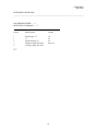
7. Identify the I/O Select Switch located on the rear panel of the electronics unit. Set the
switches to the following positions:
Switch
1
2
3
4
5
6
7
8
Position
UP
UP
DOWN
UP
DOWN
DOWN
DON’T CARE
DON’T CARE
4
OPM01PI021
April 2001
Default I/O Select Dip Switch Settings
As set, these switches provide for RS-232 serial operation at 9600 baud (Switches 1, 2 & 3),
Internal synchronization (Switch 4), sync generator off (Switches 6 & 7). (Switches 7 & 8 are not
used.)
8. NOTE: THE ISOTRAK II SYSTEM BEHAVES AS A TRANSMITTER ON THE
RS-232 AND THEREFORE A NULL MODEM CABLE IS REQUIRED. Obtain a NULL
MODEM RS-232 serial interconnection cable with a 9 pin, female "D" connector on the tracker
end of the cable. Plug one 9 pin, female "D" connector into the I/O connector located on the rear
panel of the electronics unit. Engage and lock this connection in the same manner as the receiver
and transmitter connections as indicated in steps 3 & 4.
RS-232 Cable Connection
5
OPM01PI021
April 2001
9. Most PC hosts have a 9 pin, male "D" type connector for Com 1. If you are using Com
1, plug the remaining end of the cable into the Com 1 port of the host PC, engage, and lock as
before. If your host computer has a 25 pin "D" connector for the RS-232 port, you will need a 9 to
25 pin "D" connector adapter with the proper genders. Note that this adapter must not
compromise the NULL MODEM sense of your cable.
10. Open a serial connection using the Windows program HyperTerminal. The steps are as
follows:
• Click Start, point to Programs, Accessories, and click HyperTerminal
• Double-click the Hyperterminal.exe icon
• Enter a session name, choose an icon, and click OK
• In the “Connect using” field, select Com 1 or Com 2 (depending on the tracker
connection) and click OK
In
• the “Bits per second” field, select 9600
• In the “Data bits” field, select 8 (default)
• In the “Parity” field, select None (default)
• In the “Stop bits” field, select 1 (default)
• In the “Flow control” field, select None and click OK
11. At this point, you may turn on the ISOTRAK II using the power switch located on the
back panel of the SEU. Note the “power on” indicator located on the front panel of the electronics
unit. It should immediately turn on (without flashing) to a steady-on state thereby indicating that
the system is ready to operate.
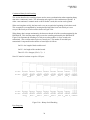
12. You may now use the HyperTerminal Program to exercise the system. After sending an
upper case “P” command to the system, the six-degree-of-freedom output data will be sent to the
host. The data consists of a header (0s, where s equals the station number) and six columns of data
as follows: (Note: these values represent an arbitrary placement of the receiver and transmitter.)
1
01
2
3
4
5
6
7
16.08 -0.38 0.71 3.05 1.12 -0.67
ISOTRAK II Data Record
Column Function
1
2
3
4
5
6
7
01 Header (not shown above)
X position in inches
Y position in inches
Z position in inches
Azimuth attitude in degrees
Elevation attitude in degrees
Roll attitude in degrees
Because you have locked the receiver in one position relative to the transmitter (Step 5), the data
output will not change regardless of the number of data samples you take.
6
OPM01PI021
April 2001
13. Remove the receiver, move it approximately six inches toward the transmitter, secure it
in place, and take a data point. The value of the X position data will decrease by approximately
six inches. The Y and Z values will remain roughly the same as the original data. If you left the
attitude of the receiver approximately the same, as it was when you started, then the attitude data
will be approximately the same also.
14. Again, remove the receiver and without moving its position, try twisting it in azimuth
(in the same plane as the 2 x 4) approximately 45 degrees and lock it down with tape. Now take
another data point by pressing “P”. The first four columns will be approximately as they were in
Step 13, but the Azimuth data in column 5 will have changed by approximately 45 degrees.
15. Experiment with the system as shown in Step 14 to demonstrate that it measures the
position and orientation (six-degrees-of-freedom) of the receiver with respect to the transmitter.
16. If the system fails to produce six-degree-of-freedom data, carefully go over the above
procedure in a systematic fashion, checking connections and switch settings especially. When all
else fails, call us.
7
OPM01PI021
April 2001
Contacting Polhemus Customer Service
If problems are encountered with the ISOTRAK II system or if you are having difficulty
understanding how the commands work, help is just a telephone call away. Call Polhemus at (800)
357-4777 and select “2” for Customer Service and then “1” Technical Support. Polhemus is open
Monday through Friday, 8:00 AM to 5:00 PM, Eastern Standard Time. For the most part, our
customer service engineers are usually able to solve problems over the telephone and get you back
into the fast lane right away. Help is also available on our web page at www.polhemus.com.
Simply double-click Technical Support, then click [email protected] to send us an email
describing the problem or question.
If a problem requires repair of your system, the customer service engineer will issue a Return
Merchandise Authorization (RMA) number so you can return the system to the factory. Please
retain and use the original shipping container, if possible, to avoid transportation damages (for
which you or your shipper would be liable). Please do not return any equipment without first
obtaining an RMA number. If your system is still under warranty, Polhemus will repair it free of
charge according to the provisions of the warranty as stated in the warranty section of this
document. The proper return address is:
Polhemus Incorporated
40 Hercules Drive
Colchester, VT 05446
Attention RMA #____
Telephone (From w/in the U.S.):
Telephone (From outside the U.S.):
Fax #:
8
(800) 357-4777
(802) 655-3159
(802) 655-1439
OPM01PI021
April 2001
ISOTRAK II Commands Index
Cmnd
Ltr
ISOTRAK II Command Title
Brief Description
Page
A
B
b
C
c
E
e
F
f
H
I
i
K
l
m
N
O
P
r
R
S
t
T
U
u
V
v
x
Y
Ctrl D
Ctrl E
Ctrl Q
Ctrl S
Ctrl Y
Defines reference frame and origin
Sets AER to zero
Removes new reference set by B
Enables continuous data output
Disables continuous data output
Enables Digitizer “Point” Mode
EnablesDigitizer “Run” Mode
Enables ASCII output format
Enables binary output format
Defines operating side of transmitter
Control output by receiver movement
Enables Digitizer Track Mode
Enables input signal averaging
Turns a receiver station off or on
Disables input signal averaging
Modifies stylus tip offsets
Selects Items for output in data record
Requests a single data output record
Modifies transmitter mounting frame
Clears previous alignment data
Requests a system status record
Extended Commands Toggle Switch
Tracker as opposed to Digitizer mode
Sets XYZ measurements to inches
Sets XYZ measurements to centimeters
Sets XYZ operational envelope
Modifies AER filter parameters
Modifies the XYZ filter parameters
Enables Stylus Tip Calibration
Converts output of switch functionality
Disables Digitizer Track Mode
Allows data to be transmitted
Restricts data from being transmitted
Invokes start up as if power was cycled
34
38
39
40
41
44
43
46
47
48
51
45
53
54
56
57
58
62
63
37
64
67
68
69
70
71
73
76
42
80
81
83
82
79
Alignment Reference Frame
Boresight
Unboresight
Continuous Print Output
Disable Continuous Printing
Digitizer “Point” Mode
Digitizer “Run” Mode
Enable ASCII Output Format
Enable Binary Formatted Output
Hemisphere of Operation
Define Increment
Track Mode
Enable Quiet Mode
Active Station State
Disable Quiet Mode
Define Tip Offsets
Define Output List
Single Record Transmission
Transmitter Mounting Frame
Reset Alignment
System Status
Extended Commands
Enable Tracker Mode
Set Unit Inches
Metric Conversion Units
Position Operational Envelope
Attitude Filter Parameters
Position Filter Parameters
Enable Digitizer Mode
Compatibility Mode
End Track Mode
Resume Data Transmission
Suspend Data Transmission
Re-initialize System
9
OPM01PI021
April 2001
2.0 TECHNICAL OVERVIEW
The ISOTRAK II tracking system uses electro-magnetic fields to determine the position and
orientation of a remote object. The technology is based on generating near field, low frequency
magnetic field vectors from a single assembly of three concentric, stationary antennas called a
transmitter, and detecting the field vectors with a single assembly of three concentric, remote
sensing antennas called a receiver. The sensed signals are input to a mathematical algorithm that
computes the receiver's position and orientation relative to the transmitter.
The ISOTRAK II consists of a System Electronics Unit (SEU), one or two receivers, a
single transmitter, a power supply and a power cord. The system operates at a carrier frequency of
8.013 kHz. The ISOTRAK II interfaces to the host computer via RS-232 serial communication. A
single receiver may be operated at the fastest update rate (60 Hz), or two receivers at one half this
rate (30 Hz). Of course, the unit must be set to output at a high enough baud rate to receive data at
these update rates. Mixed rates are not permitted meaning that all active receivers operate at the
same update rate, i.e. one cannot be operated faster than the other. Active receivers are selected by
physical receiver cable connections and software configuration commands.
Additionally, the ISOTRAK II may be used with a stylus or a 3BALL device instead of a
standard package receiver. Tip offsets are automatically calculated for the stylus and no special
commands are required for this mode of operation. Switch functionality is provided with both the
stylus and 3BALL device. The stylus and 3BALL must be used in the Receiver Port labeled
“one.”
10
OPM01PI021
April 2001
3.0 SPECIFICATION
Position Coverage
The system will provide the specified accuracy when the receivers are located within 30" (76 cm.)
of the transmitter. Operation with separations up to 60" (152.4 cm) is possible with reduced
accuracy.
Angular Coverage
The receivers are all-attitude.
Static Accuracy
0.10" (0.24 cm) RMS for the X,Y,or Z receiver position, and 0.75° RMS for azimuth, elevation, or
roll receiver orientation.
Resolution
0.0015 inches/inch of range (0.0038 cms/cm of range), and .1°.
Latency
20 milliseconds unfiltered and 40 milliseconds filtered, from center of receiver measurement
period to beginning of transfer from output port.
Output
Software selectable. Cartesian coordinates of position and Euler orientation angles are standard.
English or metric units and ASCII or binary outputs also are selectable.
Update Rate
One receiver:
60 updates/second
Two receivers: 30 updates/second
11
OPM01PI021
April 2001
Carrier Frequency
The ISOTRAK II carrier frequencies is 8013 Hz
Interface
RS-232C serial port with software selectable baud rates of 1200, 2400, 4800, 9600, 19200, 38400,
57600, 115200, ASCII or Binary formats. The factory default setting is 9600 baud, ASCII format.
Operating Environment
Large metallic objects, such as desks or cabinets, located near the transmitter or receivers may
adversely affect the performance of the system. Many walls, floors, and ceilings also contain
significant amounts of metal.
Operating Temperature
10°C to 40°C at a relative humidity of 10% to 95% non-condensing.
Physical Characteristics
SEU: Width 11.38" (28.91 cm.), length 11.06" (28.90 cm.), height 3.63" (9.22 cm.), weight 5.0 lb.
(2.26 Kg.).
Transmitter: Width 2.15" (5.5 cm.), length 2.15" (5.5 cm.), height 2.3" (5.8 cm.), weight 0.6 lb.
(0.27 Kg.) excluding attached cable. The Transmitter may be purchased with either 10' or 20'
cables.
Receiver: Width 1.1" (2.83 cm.), length 0.90" (2.29 cm.), height 0.60" (1.52 cm.), weight 0.6 oz.
(17.0 gm.) excluding attached cable. Receivers may be purchased with either 10' or 20' cables.
Stylus: Length 7.00" (17.78 cm.) including tip, or the shorter version Stylus, length 3.5” (6.04
cm), maximum barrel diameter 0.75" (1.9 cm.), handle diameter 0.375" (0.95 cm.), tip length 0.8"
(2.03 cm.), tip diameter 0.156" (0.4 cm.), weight 2.5 oz. (28.3 gm.) excluding attached cable.
Either stylus may be purchased with either 10' or 20' cables.
3BALL: A standard receiver mounted in an official #3 billiard ball fitted with an integral switch.
The 3BALL has a standard 10' cable.
12
OPM01PI021
April 2001
Power Requirements
International Power Sources Supply: Input power is 85-264 VAC, 47-440 Hz, and single phase at
30 watts.
13
OPM01PI021
April 2001
4.0 COMPONENT DESCRIPTION
4.1 SEU
The SEU is a stand-alone unit that may be located anywhere that is convenient to the work
area, AC power and the host computer. It contains the required input and output connectors and
controls to support up to four receivers, a single transmitter and the RS-232 output port. Receiver
Input(s), Transmitter Input, I/O Cables, I/O Select Switch, External Sync I/O, Video Sync Input,
and Power Input connections are located on the SEU as shown in Figure 4.1A and Figure 4.1B.
Figure 4.1A ISOTRAK II SEU, Front View
14
OPM01PI021
April 2001
Figure 4.1B ISOTRAK II SEU, Rear View
15
OPM01PI021
April 2001
4.2 Transmitter Port
The single Transmitter receptacle port is a 15 pin, male "D" type connector located on the
front of the SEU as shown in Figure 4.1A. The transmitter should be connected to the SEU before
the unit is powered on and disconnected after the unit is powered off. Caution: Do not disconnect
the transmitter while the ISOTRAK II SEU is powered on. Also, do not power on the SEU
without a transmitter connected. When routing cables, please be sure the transmitter cable is
routed separately from the receiver cables.
4.3 Receiver Ports (2)
The two Receiver receptacle ports are 15 pin, female “D” type connectors located on the
front of the SEU as shown in Figure 4.1A. The receiver(s) should be connected to the SEU before
the unit is powered on and disconnected after the unit is powered off. It is permissible to
disconnect and re-connect receivers while the SEU is powered on, however, it is necessary to send
the Ctrl Y reset command after doing so. This will allow the receiver’s precise characterization
matrix to be loaded into the ISOTRAK II memory. Again, rout the receiver cables separately from
the transmitter cable.
4.4 Power Indicator
A green LED power on indicator is located on the front of the SEU as shown in Figure
4.1A. Upon power up, the indicator will immediately turn to a steady-on mode indicating that the
system is ready for operation.
4.5 I/O Select Switch
The I/O Select Switch is an 8 position switch located on the rear panel of the SEU as shown
in Figure 4.1B, Rear View and is only read on power up or system re-initialization (Ctrl Y
command). The purpose of these switches is to select the I/O baud rate and the synchronization
mode to be used. The switch positions and their corresponding functions are as follows:
Note: UP position is a logic "1" and DOWN is a logic "0".
Switch
Position
1
2
3
4
Function
Baud rate select
Baud rate select
Baud rate select
Sync Mode: Internal = “1” Up
External = “0” Down
16
OPM01PI021
April 2001
5
6
7
8
Sync Generator Select
Sync Generator Select
Not Used
Not Used
The Baud rate select logic for switches 1, 2 and 3 is as follows:
Baud Rate
1200
2400
4800
9600
19200
38400
57600
115200
1
0
1
0
1
0
1
0
1
2
0
0
1
1
0
0
1
1
3
0
0
0
0 (factory setting)
1
1
1
1
The system reads the baud rate switches only on power up or system re-initialization.
Therefore, if you change the switches to obtain a different baud rate, you must restart the system
either by recycling the power or by using the Ctrl Y command.
Note: High baud rates such as 115.2K generally require a short, well-made RS-232 cable in order
to achieve error-free performance.
The Sync Mode (switch 4) is to allow the selection of either Internal Sync or External Sync.
The switch is read only on power-up or after sending the Ctrl Y command. The Sync Generator is
a “built in” 30 Hz square wave generator having a differential driver.
The sync generator select logic for switches 5 and 6 is as follows:
Sync Gen
5
6
Off
On
Not Used
Not Used
0
1
1
0
0
1
0
1
Note: UP position is a logic "1" and DOWN is a logic "0".
17
OPM01PI021
April 2001
4.6 External Sync I/O
The Sync I/O connector is located on the rear panel of the SEU as shown in Figure 4.6A.
The connector is a single modular telephone socket. All input and output signals must be
differential TTL compatible. If the output is employed in the user’s system, it must be interfaced
with the same differential TTL circuitry. The Sync In and Sync Out signals are also compatible
with RS-422 specifications. The pin assignments are as follows and their numbering is shown in
Figure 4.6A:
Figure 4.6A. Sync Connector Identification (Input & Output)
Pin #
Function
4
3
2
1
Ground
Sync /
Sync
Ground
4.7 RS-232 I/O
The RS-232 I/O serial connector is a standard, 9 pin, male, "D type" connector located on
the rear panel of the SEU as shown in Figure 4.1B. The pinout identification for this connector is
as follows:
Pin #
1
2
3
4
5
6
7
8
9
Function
Not used
RxD (Receive Data)
TxD (Transmit Data)
Not used
GND
Not used
RTS* (Not Used)
CTS* (Not Used)
Not used
Pin 7 is electrically shorted to Pin 8 on the circuit board. ISOTRAK II does not use RTS and CTS.
If possible, electrically shorting these pins (functions) in your interface cable is recommended.
Note: Many commercially available cables do not include connections for all pins, so do not
assume that these connections are made. Please refer to Appendix D to find the specific
interconnection scheme for your host computer in order to obtain a reliable serial interface.
18
OPM01PI021
April 2001
If you do not find your particular host's RS-232 I/O interconnection scheme in Appendix D, call
Polhemus and FAX a copy of your host computer's pin out identification from its user's manual.
Polhemus will respond with advice on how to make the serial connection between your ISOTRAK
II and your host computer. (Our Telephone and FAX numbers and email address can be found in
Section 1.)
4.8 Power Input Receptacle
The Power Input is a 5 contact, female, shielded DIN type receptacle located on the rear
panel of the SEU as shown in Figure 4.1B. Pin outs for this receptacle are as follows:
Pin #
1
2
3
4
5
Function
GROUND (Digital)
GROUND (Analog)
+5 VDC
-15 VDC
+15 VDC
Note: Digital ground, pin 1, is not electrically shorted to analog ground, Pin 2 on the PCB. (They
are electrically connected in the power supply.)
4.9 Transmitter
The Transmitter is the device which produces the electro-magnetic field and is the reference
for the position and orientation measurements of the receivers. It is usually mounted in a fixed
position to a non-metallic surface or stand, which is located in close proximity to the receivers.
The Transmitter is dimensionally shown in Figure 4.13A including the position of the electrical
center. There are 4, 1/4" - 20 NC tapped holes provided on the bottom surface for mounting.
Nylon hardware (supplied) should be used when locating the Transmitter in a fixed position.
Note: Please be sure to route the transmitter cable separate from the receiver cables in order to
avoid possible noise problems.
19
OPM01PI021
April 2001
Figure 4.13A Transmitter Dimensions (In Inches)
Figure 4.13B Transmitter
20
OPM01PI021
April 2001
4.10 Receiver(s)
The receiver is the smaller device whose position and orientation is measured relative to the
Transmitter. The Receiver is dimensionally shown in Figure 4.14A including the position of the
electrical center. The Receiver package provides 2 mounting holes for #4 nylon screws (supplied)
in the event that Receiver mounting is required.
Note: Nylon hardware is only required when the hardware will be in direct contact with the
transmitter or receiver. A testing surface where the devices will be used (a table for example),
could have small metal hardware like screws, nuts, and bolts which probably would not affect the
accuracy of the system. Again, please be sure to route the receiver cables separate from the
transmitter cable.
4.11 Stylus
The stylus is a pen shaped device with a receiver coil assembly built inside and a push
button switch mounted on the handle to effect data output. The Position measurements are relative
to the tip of the stylus, due to a precise factory calibration. The Stylus is dimensionally shown in
Figure 4.15A and may be used in any of the receiver ports. The stylus functions as a receiver with
the electrical center offset from the tip of the stylus via software. Single or Continuous output
records may be obtained as a function of the integral switch. See Section 6.5 for operation with a
stylus.
4.12 3BALL
The 3BALL is a #3 billiard ball with a receiver coil assembly built inside and an integral
push button switch to effect data output. The 3BALL is shown in Figure 4.16A. It may be used in
the same manner as a stylus where single or continuous data output records may be obtained as a
function of the switch. The data are referenced to the center of the ball. Like the stylus, the
3BALL may be used in any of the receiver ports. See section 6.5 for operation with the 3BALL
device.
21
OPM01PI021
April 2001
Figure 4.14A Receiver Dimensions (In Inches)
Figure 4.14B Receiver
22
OPM01PI021
April 2001
Figure 4.15A Stylus Dimensions (In Inches)
23
OPM01PI021
April 2001
Figure 4.15B Stylus
24
OPM01PI021
April 2001
Figure 4.16A. 3BALL
4.20 Mini Receiver
The Mini Receiver is an optional device; 10-12 mm in size, whose position and orientation is
measured relative to the transmitter, like all receivers. Because of its small size, its maximum
range from the transmitter is reduced to 35%-40% that of a standard receiver.
25
OPM01PI021
April 2001
5.0 SYSTEM OPERATION
5.1 I/O Considerations
RS-232 The RS-232 is the most commonly used port both in binary and ASCII formats because of
its commonality and the fact that it supports high baud rates. The RS-232 port should be used
where host to ISOTRAK II physical separation distances are no greater than 50 feet and baud rates
can be kept low. (Higher baud rates will require shorter cable lengths for reliable operation.)
There are two modes of operation with the RS-232; with Hardware Handshake (HH) and without
HH.
Ensure that your RS-232 cable connects the ISOTRAK II TRANSMIT data pin (pin 3) to
the HOST'S RECEIVE data pin and that the ISOTRAK II RECEIVE data pin (pin 2) is
connected to the HOST'S TRANSMIT data pin. Also ensure that the RS-232 cable connects the
ISOTRAK II GROUND (pin 5) to the HOST'S GROUND pin. Note that the host computer’s
ground pin may be designated as "Signal Ground" or some other comparable phrase. In addition to
proper cable connections, the I/O select switch must be set correctly, according to the host
communication software. See diagram below for RS-232 cable connections without hardware
handshaking:
RS-232 Cable Connections
ISOTRAK II
HOST
Transmit (pin 3) ---------------------------------------------- Receive
Receive (pin 2) ------------------------------------------------ Transmit
Ground (pin 5) ------------------------------------------------- Ground
Note: The EIA standard RS-232C recommends that the maximum length of the interface cable
should be less than 50 feet. Shielded cable is also recommended, in order to avoid possible
interference.
The RS-232 interface of the ISOTRAK II uses the following protocols:
•
•
•
•
•
Start Bits:
Data Bits:
Parity:
Stop Bits:
Baud Rate:
1
8
None
1
Selectable
5.2 Powering Up ISOTRAK II
To power-up your ISOTRAK II system, first ensure that the power switch on the back panel
26
OPM01PI021
April 2001
of the ISOTRAK II is in the “off” position and the power supply brick is not plugged into the AC
wall outlet. Then connect the power cable from the power supply to the DIN power connector on
the rear panel of the ISOTRAK II. Connect the power cord to the power supply brick and plug it
into the AC wall outlet. Configure the dip switch settings on the I/O select switch. Plug in
transmitter, receivers and RS-232 cable and turn the power switch to the ON position. On power
up, the power indicator will immediately turn to a "steady-on" state, which indicates that the
system is operational.
Important Note: Do not connect or disconnect the power cable to the ISOTRAK II
electronics unit while it is powered on or while the power supply brick is energized. Internal
component damage could result.
Initial Power Up Procedure
•
•
•
•
•
•
•
Verify ISOTRAK II power switch is off
Verify power supply brick is not energized (not plugged into the wall outlet).
Connect the power cable from the brick to the power connector on rear panel of ISOTRAK II
Plug the power supply brick into the AC wall outlet
Configure the I/O select dip switches
Plug in the transmitter, receiver(s), and RS-232 cable
Turn on the ISOTRAK II power switch
5.3 Configuration Changes
Although receivers can be connected or disconnected while the unit is powered on, it is not
normal operating practice. However if it is necessary to do this, it is important to either cycle the
system power or send the Ctrl Y reset command. This allows the device characterization data for
the receiver to be read and applied to future measurements. Normal system accuracy cannot be
achieved unless the receiver characterization data has been read properly.
Important note: Do not connect or disconnect the transmitter while the ISOTRAK II system is
powered on.
5.4 Synchronization
Synchronization defines and controls the precise time that an ISOTRAK II system
measurement cycle will start and thereby controls the tracking output from an application system
point of view. The ISOTRAK II system has two distinct synchronization modes that are controlled
by switch 4 of the I/O select switches: Internal sync and External sync.
27
OPM01PI021
April 2001
5.5 Internal Sync
Internal synchronization is the normal operating mode for the ISOTRAK II system. Switch
4 of the I/O select switches should always be set to on (logic “1”or “up” position) unless an
external sync pulse is provided. In the Internal Sync mode, each measurement cycle of the
ISOTRAK II system starts immediately after the previous cycle ends. In internal sync mode, the
system performs one measurement cycle every 16.67 milliseconds and any external sync signal is
ignored.
5.6 External Sync
The external sync mode is invoked by turning switch 4 of the I/O select switches off (logic
“0” or “down” position). The External Sync mode allows the user to define when the ISOTRAK II
system measurement cycle will start, by means of a user supplied external sync pulse. This mode
may be used to synchronize other peripheral instrumentation to the ISOTRAK II data collection
cycle or to slow the ISOTRAK II to a known and desired rate. To initiate the External Sync mode
an external signal must be input to the SYNC IN port. In the external sync mode, the ISOTRAK II
waits for an external sync signal in order to perform a single measurement cycle.
Note: Perform this function with the position and attitude filters off until the sync condition is
established.
In external sync mode, the ISOTRAK II system will perform one and only one measurement cycle
for each external sync input that transitions from the inactive state to the active state. The external
sync signal requirements are as follows:
•
Driver – Differential, from a 26LS31 or similar.
•
Input – To ISOTRAK II sync I/O connector that has an LM339 differential receiver.
•
Minimum Pulse Width – 100 microseconds
•
Maximum Rep Rate – 16.67 milliseconds.
•
Inactive State – Between 0 and 0.4 volts.
•
Active State – Between 2.4 and 5.0 volts.
5.7 Multiple Systems Synchronization
When using more than one ISOTRAK II in the same area, it is important to sync the units
together so that they will not interfere with each other and produce noisy data. When they are
synced together, the ISOTRAK II systems are operated on a time-shared basis where the maximum
update rate is 30 Hz per system when each system has a single receiver connected. Follow the
procedure below to establish this condition:
28
OPM01PI021
April 2001
•
The I/O select switches of the first ISOTRAK II system should be set as follows: Switch 4 in
the “down” position (to select external sync), switches 5 and 6 in the “up” position (to enable
the 30 Hz square wave sync generator, the external sync signal that will be supplied to the
second unit.)
•
The I/O select switches of the second ISOTRAK II system should be set as follows: Switch 4
in the “down” position (to select external sync), switches 5 and 6 in the “down” position (to
disable the 30 Hz square wave sync generator on that unit).
•
Connect the two units together using a standard, four conductor modular telephone cable.
(The cable plugs into each unit’s Sync I/O connector.)
5.8 Output Considerations
Most applications of the ISOTRAK II system involve using its data output to manipulate
some type of computer graphics in real time. In this condition, it is extremely important to allow
the data to be utilized as quickly as possible and to avoid latency or lag. Lag is defined as the
interval of time between requesting a tracker data point and receiving it into the host computer.
Factors that could increase the lag are as follows:
•
•
•
•
Baud Rate
Output Record Length
Filtering
Data Format (binary is more efficient than ASCII)
The ISOTRAK II baud rate should be set to the highest setting that is compatible with the
host computer and the communication software. Although the ISOTRAK II system runs at 60 Hz,
it may appear that it is running slower if the output is constrained by a slow baud rate. The
ISOTRAK II is capable of running at speeds of up to 115,200 as selected by the I/O Select
Switches on the back panel.
The ISOTRAK II default output record contains measurements for X, Y, Z in inches and
Azimuth, Elevation, and Roll in degrees. This output format can be changed to Direction Cosines
with “O” command (see section 6). Although the ISOTRAK II offers different combinations of
output selections, it is best to keep the output record length constrained only to the data that is
needed. Excessive data in the output record can slow down the transmission and not allow the
system to output data to the host at the maximum update rate.
The ISOTRAK II contains an adaptive filter that is designed to control noise in the data
output. The filter can be applied to Position or Orientation or both and can be activated with
“simple” commands that select “low”, “medium”, or “heavy” filtering. It should be noted that the
effect that is seen in the data may have or appear to have a slower dynamic response with medium
or heavy filtering selected.
When using the ISOTRAK II binary format, there are two import factors that should be
considered: Serial encoding and byte swapping.
29
OPM01PI021
April 2001
Continuous Binary Serial Encoding
This section describes the encoding scheme used to ensure synchronization when outputting binary
data in the “continuous” mode. This information only applies to this combination of options. If
either “non-continuous” transmit mode or ASCII format is used, this section can be ignored.
When receiving data serially, the host needs a way to recognize the beginning of each data record.
This recognition is accomplished by insuring that the high order bit of each 8 bit byte is zero
except in the first byte of each record as shown in Figure 5.8A.
When binary data is output continuously, the host must decode all of the records transmitted by the
ISOTRAK II. This decoding must simply reverse the encoding performed by the ISOTRAK II.
Figure 5.8A illustrates the encoding of a 14-byte record to produce a 16-byte record to be
transmitted. (The overflow makes up the two extra bytes.) The number of encoded bytes
transmitted is computed from the number of actual bytes as follows:
Let LD = the length of the decoded record.
Let LE = the length of the encoded record.
Then LE = LD + Integer( (LD-1) / 7) + 1.
Note: LE must be less than or equal to 125 bytes.
Decoded:
Encoded:
Decoded:
Encoded:
+----------------------------------------------------------------------------+
|
+-----------------------------------------------------------------+|
|
|
+------------------------------------------------------+||
|
|
|
+-------------------------------------------+|||
|
|
|
|
+--------------------------------+||||
|
|
|
|
|
+---------------------+|||||
|
|
|
|
|
|
+----------+||||||
|
|
|
|
|
|
|
|||||||
bbbbbbbb bbbbbbbb bbbbbbbb bbbbbbbb bbbbbbbb bbbbbbbb bbbbbbbb
|||||||
|||||||
|||||||
|||||||
|||||||
|||||||
|||||||
|||||||
|||||||
1bbbbbbb 0bbbbbbb 0bbbbbbb 0bbbbbbb 0bbbbbbb 0bbbbbbb 0bbbbbbb 0bbbbbbb
BYTE 1
BYTE 2
BYTE 3
BYTE 4
BYTE 5
BYTE 6
BYTE 7
OVERFLOW
|
Header
|
X
|
Y
|
Z
+----------------------------------------------------------------------------+
|
+-----------------------------------------------------------------+|
|
|
+------------------------------------------------------+||
|
|
|
+-------------------------------------------+|||
|
|
|
|
+--------------------------------+||||
|
|
|
|
|
+---------------------+|||||
|
|
|
|
|
|
+----------+||||||
|
|
|
|
|
|
|
|||||||
bbbbbbbb bbbbbbbb bbbbbbbb bbbbbbbb bbbbbbbb bbbbbbbb bbbbbbbb
|||||||
|||||||
|||||||
|||||||
|||||||
|||||||
|||||||
|||||||
|||||||
1bbbbbbb 0bbbbbbb 0bbbbbbb 0bbbbbbb 0bbbbbbb 0bbbbbbb 0bbbbbbb 0bbbbbbb
BYTE 8
BYTE 9
BYTE 10
BYTE 11
BYTE 12
BYTE 13
BYTE 14 OVERFLOW
Z
|
Az
|
El
|
Rl
|
Figure 5.8A – Binary Serial Encoding
Byte Swapping
30
OPM01PI021
April 2001
Byte swapping refers to the manner in which the microprocessor chips handle the 16-bit integer
values when transferring between their internal memory and main memory. Many common
microprocessors “swap” the two bytes of a 16-bit integer when transferring it. In other words,
when sending it to main memory, the low order byte is stored first, then the high order byte. This
order is expected when the processor reads back a 16-bit integer from main memory to its internal
memory.
Therefore, if the host utilizes a processor that employs this byte swapping technique, binary data
received from the ISOTRAK II is immediately usable as 16-bit integers (after decoding as
described in Serial Encoding.) However, if the host processor does not swap the high and low
bytes automatically, the binary data must be swapped by the host to match the expectations of the
ISOTRAK II as follows:
16-Bit Integer
High Byte Low Byte
As Transmitted
Low Byte High Byte
31
OPM01PI021
April 2001
6.0 System Commands
There are two classes of system commands: one class for configuring the state of the
system, and the other for controlling its operation. The commands are presented in functional,
alphabetical order. Where applicable, examples of the command in use will be given. All
commands are input on the RS-232 serial port and consist of ASCII characters. Additionally,
format notations and conventions for commands and outputs are presented first.
6.1 Command Format Notation and Convention
Use the following format notation to enter commands:
[]
Items shown inside square brackets are optional. To include optional items, type only the
information inside the brackets. Do not type the brackets.
<>
Represents an ASCII carriage return or “enter”. Whenever shown this value must be
present to terminate the command sequence.
...
An ellipsis indicates that you can repeat an item.
,
A comma represents a delimiter in a list of optional parameters. The comma must be
present for those parameters which are omitted except for the case of trailing commas. For
example,
Qs,p1,,,p4<>
is the proper command format when omitting parameters p2 and p3. Commas following the
parameter p4 are not required if parameters p5 and p6 are omitted.
|
A vertical bar means either/or. Choose one of the separated items and type it as part of the
command. For example,
ON|OFF
indicates that you should enter either ON or OFF, but not both. Do not enter the vertical
bar.
32
OPM01PI021
April 2001
6.2 Command Format Notes
(1)
All commands and alphabetic parameters are case sensitive. They must be entered in upper
or lower case as defined in the syntax.
(2)
For those commands involving an optional list of parameters, if some of the parameter
values are omitted the current system retained value of that parameter is used in its place.
(3)
The RELATIVES field contains a list of those commands which provide related
information to the system. For example, the unboresight command “b” is a relative to the
boresight command “B”.
(4)
The term station is a transmitter-receiver pair. The two receivers paired with the one
available transmitter are assigned station numbers one and two.
(5)
A numeric floating point value will be accepted by the machine if any of the following
formats are used. For example: 3.0 may be specified as:
3
3.
3.0 or
3.0 E+00
See each command's format for generally accepted accuracy range.
(6)
The notation R(Sxx.xxxB) represents the ASCII output format for the specific data element,
where:
R
S
X
.
B
H
is the repeat count and what follows in parenthesis is repeated R times
is the sign byte, either +, -, or space (for +)
is a decimal digit (0...9)
is a decimal point
is a blank
is a hexadecimal digit (0...F)
Example: A format 3(Sx.xxxxB), would be output as:
-1.1111 2.2222 -3.3333
(7)
For discussion purposes, all “Examples” assume only 1 receiver is used, connected to the
station 1 receptacle.
6.3 Command/Output Listing
See pages that follow.
33
OPM01PI021
April 2001
ALIGNMENT REFERENCE FRAME
A1
_______________________________________________________________________________
Syntax:
A1,[Ox],[Oy],[Oz],[Xx],[Xy],[Xz],[Yx],[Yy],[Yz]<>
or
A1<> to read back the current alignment
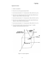
Purpose:
The alignment command does two things. It defines a reference frame to which all
position and orientation output data is referred. In addition, it creates a new
origin point where the X, Y, Z measurements would equal 0,0,0 if the receiver
were placed there. See figure 6.3A. An example of where this command would
be useful is a sloped test surface that the user wanted referenced to the transmitter.
This would obtain congruence between the ISOTRAK II and the axes of the
sloped surface.
NOTE: This command operates incrementally. If the command is entered and the
user then changes his/her mind, the 'R' command must be used to reset the
alignment reference frame BEFORE the command is re-entered. This is
ESPECIALLY IMPORTANT to remember if the user makes an error and wants to
correct the erroneous input because the new alignment would be additive to the
mistake. The command parameters are:
Ox,Oy,Oz
the Cartesian coordinates of the origin of the new reference frame.
Xx,Xy,Xz
the coordinates of the second point defining the positive direction
of the X-axis of the new reference frame.
Yx,Yy,Yz
the coordinates of a third point that is in the positive Y direction
from the X-axis.
Relatives:
R
Range:
No Range Restriction Enforced
Default:
The transmitter reference frame is the default alignment reference frame.
(0,0,0,166.32,0,0,0,166.32,0) in centimeters
Example:
To perform an alignment, follow the steps listed below:
34
OPM01PI021
April 2001
Alignment Procedure
1. Send the command R1<>
2. Place the receiver at the proposed origin location
3. Press P and write down the X, Y, Z measurements (These will be Ox, Oy, Oz)
4. Move the receiver along the proposed X axis from the origin defined in step 2
and place it about 24 inches in front of this origin.
5. Press P and write down the X, Y, Z measurements (These will be Xx, Xy, Xz)
6. Move the receiver along the proposed Y-axis from the origin defined in step 2
and place it about 24 inches from the transmitter.
7. Press P and write down the X, Y, Z measurements (These will be Yx, Yy, Yz)
8. Using all of the data that has been written down in steps 1-7, send the
command A1,Ox,Oy,Oz,Xx,Xy,Xz,Yx,Yy,Yz<>
Figure 6.3A System Alignment
35
OPM01PI021
April 2001
ALIGNMENT REFERENCE FRAME
_______________________________________________________________________________
SUB-RECORD IDENTIFIER .... A
INITIATING COMMAND ....... A
byte(s) Identification
Format
1
1
1
21
21
21
2
_____
68
A1
A1
A1
3(Sxxx.xx)
3(Sxxx.xx)
3(Sxxx.xx)
Record type, "2"
“1”
"A"
Origin coordinates
Positive X-axis coordinates
Positive Y-axis coordinates
Carriage return, line feed
36
OPM01PI021
April 2001
RESET ALIGNMENT REFERENCE FRAME
R
_______________________________________________________________________________
Syntax:
R1<>
Purpose:
This command resets the alignment reference frame for the specified station to the
station reference frame. It provides an easy way to re-align the reference frame to
the factory default values or the transmitter’s own reference frame.
Relatives:
A
Example:
Any time the alignment command (A1...) used, it is best to send the reset
alignment command (R1<>) first. That way, there is no risk of building one
alignment on top of another. See Standard Alignment Procedure listed under
Alignment Reference Frame.
37
OPM01PI021
April 2001
BORESIGHT
B
_______________________________________________________________________________
Syntax:
Bstation<>
Purpose:
This command causes the tracking receiver to be electronically aligned in
orientation with the user system coordinates. This results in azimuth, elevation
and roll outputs equal to 0,0,0 at the current orientation. The tracker then
produces outputs relative to this reference. Any receiver orientation can be
designated as the zero orientation point. The command parameter is defined as:
station
the number of the station to be boresighted.
Relatives:
b
Default:
The zero orientation condition occurs when the receiver orientation corresponds to
the transmitter orientation.
Example:
The receiver may be mounted on a person’s head to measure where it is pointing.
When the user’s head is looking at a given object, he may want the system angular
outputs to be zero. The user can designate this receiver orientation as the zero
orientation by sending the boresight command:
B1<>
This results in azimuth, elevation, and roll outputs of zero at this orientation. As
the user’s head moves away from the boresight point, the orientation angles are
still measured relative to the transmitter, with the zero points shifted to the point
where the boresight occurred.
Note:
Do not use this command when using a stylus with the ISOTRAK II. The
boresight command will nullify the tip calculations and induce errors in the
X, Y, Z measurements.
38
OPM01PI021
April 2001
UNBORESIGHT
b
_______________________________________________________________________________
Syntax:
bstation<>
Purpose:
This command removes the current boresight. The system boresight rotation
matrix is reset to the identity matrix for the specified station. The command
parameter is defined as:
station the number of the station to be boresighted.
Relatives:
B
Example:
If the user issued the Boresight command while the receiver was at a particular
orientation and then later decided that it would be best not to use a Boresight, or
there was a need to see what the system reads without the Boresight, then the
Unboresight command could be used as follows:
b1<>
(P, the command to request a single data record, could then be used to read the
default orientation angles.)
39
OPM01PI021
April 2001
CONTINUOUS PRINT OUTPUT
C
_______________________________________________________________________________
Syntax:
C
Description:
Output transmit mode refers to whether the system automatically transmits data
records to the host (continuous mode), or the host must request data records by
sending a command to the system each time (non-continuous mode).
Purpose:
This command enables the continuous print output mode. When the system is in
continuous mode, the data points from all stations are requested automatically and
are scrolled one after the other in a continuous “stream”. If more than one station
is enabled, then the data from each station will be displayed in numerical order
(station 1 first, station 2 second.)
Relatives:
c, P
Default:
Continuous output mode is disabled.
Example:
If the system is being used in an application where a fast update rate is critical,
(driving real-time computer graphics, like an animated character for example) then
the continuous output configuration should be enabled. To enable continuous
output mode, send the command as follows:
C
Data from the ISOTRAK II will now scroll continuously across the serial port to
the host computer.
40
OPM01PI021
April 2001
DISABLE CONTINUOUS PRINTING
c
_______________________________________________________________________________
Syntax:
c
Purpose:
This command disables the continuous print output mode. After sending this
command, the continuous data stream from the ISOTRAK II to the host computer
will stop.
Relatives:
C, P
Default:
Continuous output mode is disabled
Example:
If the system is set to continuous output mode with the “C” command, the user
may wish to stop the data stream to adjust other system parameters. This can be
accomplished by sending the command:
c
The continuous data output mode will be disabled and the data stream will stop.
41
OPM01PI021
April 2001
ENABLE DIGITIZER MODE
Y
_______________________________________________________________________________
Syntax:
Y
Purpose:
This command converts the ISOTRAK II from “tracker” mode of operation to
“digitizer” mode when a stylus is being used in lieu of a receiver. Digitized data
from the receiver coil assembly in the stylus is then translated to the stylus tip.
This command is a toggle, so repetition of the command converts the system back
to tracker mode of operation.
Default:
System default is “tracker” mode
Relatives:
C, e, E, i
Example:
If the user wanted to receive data every time the stylus button was activated, the
following commands must be sent:
1. Send the Y command to enable “digitizer” mode. (Assuming the system was
previously in “tracker” mode.)
2. Send the E command to enable “point” mode.
3. Send the Ctrl D command to enable “compatibility” mode.
4. Send the C command to set continuous output mode.
The system will now output a data record each time the stylus button is pressed.
42
OPM01PI021
April 2001
ENABLE “RUN” DIGITIZER MODE
e
_______________________________________________________________________________
Syntax:
e
Purpose:
This command allows the user to put the ISOTRAK II into “run” digitizer mode.
Before sending the command, the system must first be in the digitizer mode.
Default:
System default is “tracker” mode
Relatives:
C, E, i, Y
Example:
The user may wish to configure the system to digitizer mode, but begin receiving
continuous data as soon as the C command is sent. To do this, the following
commands must be sent:
1. Send the Y command to enable “digitizer” mode. (Assuming the system was
previously in “tracker” mode.)
2. Send the e command to enable “run digitizer” mode.
3. Send the C command to enable continuous output mode.
The system will now automatically begin transmitting data records to the host,
without having to press the stylus button.
43
OPM01PI021
April 2001
ENABLE “POINT” DIGITIZER MODE
E
_______________________________________________________________________________
Syntax:
E
Purpose:
This command allows the user to put the ISOTRAK II into “point” digitizer mode.
In this mode, the system will send data to the host each time the stylus button is
pressed.
Default:
System default is “tracker” mode
Relatives:
C, e, i, Y
Example:
If the user wanted to receive data every time the stylus button was activated, the
following commands must be sent:
1. Send the Y command to enable “digitizer” mode. (Assuming the system was
previously in “tracker” mode.)
2. Send the E command to enable “point” mode.
3. Send the Ctrl D command to enable “compatibility” mode.
4. Send the C command to set continuous output mode.
The system will now output a data record each time the stylus button is pressed.
44
OPM01PI021
April 2001
SET TRACK DIGITIZER MODE
i
_______________________________________________________________________________
Syntax:
i
Purpose:
This command allows the user to put the ISOTRAK II into “track” digitizer mode.
The track mode is identical to the run mode except that the stylus or 3Ball switch
must be pressed once to initiate data transmission (track on). Thereafter, any
activation of the stylus or 3Ball switch may be used to alternately suspend (track
off) and resume (track on) data collection.
Default:
System default is “tracker” mode
Relatives:
C, e, E, Ctrl E, Y
Example:
The user may wish to be able to start and stop a continuous stream of data by
pressing the stylus button. To do so, the following commands should be sent:
1. Send the Y command to enable “digitizer” mode. (Assuming the system was
previously in “tracker” mode.)
2. Send the i command to enable “track digitizer” mode.
3. Send the Ctrl D command to enable compatibility mode.
4. Send the C command to enable continuous output mode.
The user will now be able to press the stylus button once to start the continuous
data stream and press the stylus button again to stop the continuous data stream
and so on.
45
OPM01PI021
April 2001
ENABLE ASCII OUTPUT FORMAT
F
_______________________________________________________________________________
Syntax:
F
Purpose:
This command enables the ASCII output data format. ASCII format means that
the data is generally human readable, while binary format is generally computer
readable. Regardless of output data format selected, all input data (commands) to
the ISOTRAK II system must be in ASCII format.
Relatives:
f
Default:
The default output data format is ASCII
Example:
If a software application is written to receive binary data from the ISOTRAK II
system and there was a requirement to take it off line temporarily to do visual
checks, the user would enable the ASCII output data format in order to be able to
easily read the ISOTRAK II data on the PC monitor. To do so, the following
command should be sent:
F
The system will now be in ASCII output data format and can be read by the user.
46
OPM01PI021
April 2001
ENABLE BINARY OUTPUT FORMAT
f
_______________________________________________________________________________
Syntax:
f
Purpose:
This command enables the binary output data format. Binary format is generally
computer readable while ASCII format is human readable.
Relatives:
F
Default:
The default output data format is ASCII.
Example:
The user may wish to write a software application for the ISOTRAK II where a
fast update rate is crucial. In order to reduce data packet size, the ISOTRAK II
could be set to output in binary instead of ASCII. This can be accomplished with
the command:
f
The ISOTRAK II will now output binary data.
47
OPM01PI021
April 2001
HEMISPHERE OF OPERATION
H
_______________________________________________________________________________
Syntax:
Hstation,[p1],[p2],[p3]<>
or
H<> to read back the current hemisphere selection
Description:
Because of the symmetry of the magnetic fields generated by the transmitter, there
are two mathematical solutions to each set of receiver data processed. Therefore,
only half of the total spatial sphere surrounding the transmitter is practically used
at any one time without experiencing an ambiguity (usually sign flips) in the X, Y,
Z measurements. This half sphere is referred to as the current hemisphere. The
chosen hemisphere is defined by an LOS (line-of-sight) vector from the transmitter
through a point at the zenith of the hemisphere, and is specified by the LOS
direction cosines.
Purpose:
Since the receiver(s) can only operate in one hemisphere at a time relative to the
transmitter, it is necessary to tell the ISOTRAK II system which side of the
transmitter they will be on, for each station. Identification of command
parameters is as follows.
station
the number of the station whose operational hemisphere is to be
modified.
p1
the x-component of a vector pointing in the direction of the
operational hemisphere.
p2
the y-component of a vector pointing in the direction of the
operational hemisphere.
p3
the z-component of a vector pointing in the direction of the
operational hemisphere.
Relatives:
None
Default:
The default hemisphere value is: 1,0,0 which is positive X or “forward”
hemisphere.
Example:
The user may decide to mount the transmitter above the test area in order to be
able to move the receiver to the positive and negative sides of X and the positive
and negative sides of Y. (Note: since the default hemisphere value is “forward”,
the user cannot move the receiver to the negative X side of the transmitter,
because the signs will flip and it will appear as if the X measurement never goes
negative.) If the transmitter is positioned above the test area, the positive Z or
“lower” hemisphere should be selected. This can be accomplished with the
48
OPM01PI021
April 2001
following command:
H1,0,0,1<>
Station one of the ISOTRAK II will now be set for the positive Z or “lower”
hemisphere.
Although the hemisphere vector is not limited to 1s and Os, the following table of
hemisphere commands may be useful:
Forward Hemisphere (+X)
H1,1,0,0<>
Back Hemisphere (-X)
H1,-1,0,0<>
Right Hemisphere (+Y)H1,0,1,0<>
Left Hemisphere (-Y)
H1,0,-1,0<>
Lower Hemisphere (+Z)
H1,0,0,1<>
Upper Hemisphere (-Z)
H1,0,0,-1<>
Figure 6.3B Hemisphere Vector
(Zenith represents the hemisphere vector)
49
OPM01PI021
April 2001
HEMISPHERE OF OPERATION
_______________________________________________________________________________
RECORD IDENTIFIER ........ H
INITIATING COMMAND ....... H
byte(s)
Identification
Format
1
1
1
7
7
7
2
____
26
Record type, "2"
Station number
"H"
Vector x-component
Vector y-component
Vector z-component
Carriage return, line feed
A1
A1
A1
Sxx.xxx
Sxx.xxx
Sxx.xxx
50
OPM01PI021
April 2001
DEFINE INCREMENT
I
_______________________________________________________________________________
Syntax:
I[distance]<>
or
I<> to read back the current increment distance selection.
Purpose:
This command allows the user to define the increment and control when data
records will be sent to the host, based on receiver movement. The “distance”
selection allows the user to specify exactly how much movement will be required
before data is produced. If the user enters ‘l<>’, the system outputs the current
distance value selection. Note: The system should be in continuous output mode
in order for this command to work properly. Definitions of the command
parameters are listed below:
distance
the minimum distance a receiver must move before a data record
is output to the host computer. The units of measure (inches or
centimeters) for the distance value, must be consistent with the
current selection of system units.
Relatives:
none
Default:
The default value is 0.0 inches, which disables the increment feature.
Example:
If the user wants the system to output data each time the receiver on station one
moves 2 inches in any axis, the following command should be entered:
I2<>
C
The system will now output a data record each time station one receiver moves
two inches in any axis.
51
OPM01PI021
April 2001
INCREMENT DEFINITION
_______________________________________________________________________________
RECORD IDENTIFIER ........ I
INITIATING COMMAND ....... I
byte(s)
Identification
Format
1
1
1
7
2
____
12
Record type, "2"
“1”
Sub-record type "I"
Distance required to move
Carriage return, line feed
A1
A1
A1
Sxxx.xx
52
OPM01PI021
April 2001
ENABLE QUIET MODE
K
_______________________________________________________________________________
Syntax:
K
Purpose:
This command allows the user to enable input signal averaging called “quiet
mode.”
Relatives:
m
Default:
Quiet mode is disabled
Example:
The user can initiate data averaging on all input signals so the system will output
position and orientation information based on averaged input data. The following
command would be sent:
K
The system will now be in “quiet mode.”
53
OPM01PI021
April 2001
ACTIVE STATION STATE
l
_______________________________________________________________________________
Syntax:
lstation<>
or
l<> to retrieve the current station status
Description:
A station is defined as a transmitter-receiver pair. The two receivers paired with
the one transmitter are assigned station numbers one and two. Although stations
are enabled simply by plugging the receivers into the ports on the ISOTRAK II
SEU, the stations can then be disabled (or enabled again) by using a software
toggle command. When a station is enabled, data records for that receiver will be
transmitted from that station. If the station is disabled, no data records from that
station will be transmitted.
Purpose:
The purpose of this command is to allow the host to toggle a station “on” or “off”
in software, depending on the current state of that station. The command
parameters are identified as follows:
Station
1 or 2
Relatives:
none
Default:
The default condition depends on the number of receivers that are currently
connected to the ISOTRAK II SEU. The default condition of a station that has a
receiver connected to it is “on”. The default condition of a station that does not
have a receiver connected to it is “off”.
Example:
A user could connect two receivers to an ISOTRAK II and then collect a data
point from one receiver at a time, after disabling the other receiver. To do so, the
following commands would be sent:
1.
2.
3.
4.
5.
6.
7.
8.
9.
Send the command l2<> to toggle station 2 off.
Press P to collect data from station 1 only.
Send the command l2<> to toggle station 2 on.
Send the command l1<> to toggle station 1 off.
Press P to collect data from station 2 only.
Send the command l1<> to toggle station 1 on.
Send the command l2<> to toggle station 2 off.
Press P to collect data from station 1 only.
Go to step 3 to continue collecting more data.
54
OPM01PI021
April 2001
At any time, the user could send the command l<> to retrieve the current station
status from the ISOTRAK II to find out which station or stations are active.
•
•
•
If both stations were active, sending l<> would yield 11000000
If only station one was active, sending l<> would yield 10000000
If only station two was active, sending l<> would yield 01000000
55
OPM01PI021
April 2001
DISABLE QUIET MODE
m
_______________________________________________________________________________
Syntax:
m
Purpose:
This command allows the user to disable input signal averaging (quiet mode) and
return the system to “normal mode.”
Relatives:
K
Default:
Quiet mode is disabled
Example:
If the system is in quiet mode, the user can deactivate data averaging on all input
signals so the system will be in “normal mode.” The following command would
be sent:
m
The system will now be in normal mode.
56
OPM01PI021
April 2001
DEFINE TIP OFFSETS
N
_______________________________________________________________________________
Syntax:
N,xoff,yoff,zoff<>
or
N<> to read back the current tip offsets
Description:
Each stylus has been factory calibrated with custom tip offsets. This is the offset
of the receiver from the tip of the stylus. The tip offsets allow the tip to act as the
measurement reference instead of the receiver coil inside the handle.
Purpose:
This command allows the user to override the factory defaults for the stylus tip
offsets. In order for this command to work, the system must first be in “Digitizer”
mode (see Y command.) Although changing the tip offsets is not recommended,
the ability to do so is available. The command parameters are listed below:
xoff
x-direction tip offset
yoff
y-direction tip offset
zoff
z-direction tip offset
Relatives:
None
Default:
Factory default tip offsets are read from the PROM inside the stylus connector on
power-up. As a result, the “N” command can only override the factory defaults
during the current operational session.
Example:
If the user created a special stylus tip attachment that extended exactly one inch
from the end of the stylus, an adjustment to the tip offsets would have to be made.
To do so, the following steps should be taken.
1. Set the ISOTRAK II to Digitizer mode by sending the command “Y”.
2. Verify that the ISOTRAK II system is in “inches” units by sending the “U”
command.
3. Read the factory tip offsets from the PROM in the connector by sending the
command N<>. (A typical factory tip offset might be 2.523, 0.004, 0.03.)
4. To add one inch to the factory calibration, type N,3.523,0.004,0.03<>
5. To verify that the tip offset was entered correctly, type N<> to read it back.
57
OPM01PI021
April 2001
OUTPUT DATA LIST
O
_______________________________________________________________________________
Syntax:
O[code#],[code#],...,[code#]<>
Description:
The output list refers to the subset of data items to be included in a data record.
Any combination of up to 32 data items that total less than or equal to 254 bytes is
permissible.
Purpose:
This command allows the user to define the list of variables to be output to the
host computer for the specified station. Any combination of up to 32 data items
that total less than or equal 254 bytes is permissible. The allowable values of the
parameters are:
Code# Data Item
0
1
2
3
4
5
6
7
8
9
10
11
ASCII space character
ASCII carriage return, line feed pair
x,y,z Cartesian coordinates of position
relative movement, x,y,z Cartesian coordinates of position; i.e., the
difference in position from the last output. This item should only be
selected if the specified station's Increment is = 0.0. See the "I" command.
azimuth, elevation, roll Euler orientation angles
x-axis direction cosines
y-axis direction cosines
z-axis direction cosines
x-axis receiver data (factory use only)
y-axis receiver data (factory use only)
z-axis receiver data (factory use only)
orientation quaternion
Relatives:
none
Default:
02,4,1<>; i.e., the three Cartesian coordinates, the three Euler orientation angles,
carriage return, and line feed for stations 1 and 2.
Example:
The user may decide to use X, Y, Z direction cosines instead of the default output
format. In order to do so, the following command should be sent:
O5,6,7,1<>
The output data for station will now be displayed as X, Y, Z direction cosines.
58
OPM01PI021
April 2001
OUTPUT ITEM LIST
_______________________________________________________________________________
RECORD IDENTIFIER ........ O
INITIATING COMMAND ....... O
byte(s)
Identification
Format
1
1
1
1
1
1
1
.
.
.
1
2
Record type, "2"
Station number
Sub-record type "O"
Output item 1
Output item 2
Output item 3
Output item 4
.
.
.
Output item N
Carriage return, line feed
A1
A1
A1
A2
A2
A2
A2
A2
A2
59
OPM01PI021
April 2001
SYSTEM DATA RECORD, ASCII FORMAT
_______________________________________________________________________________
INITIATING COMMANDS ..... P or in continuous mode
Item
Identification
Format
1
2
3
Record type, “0” or System Error Code
Station Number
Blank
A1
A1
A1
ASCII space character
Carriage return, line feed
X,Y,Z position Cartesian Coordinates
Relative X,Y,Z Cartesian Coordinates
Az, El, Roll Euler orientation angles
X-axis Direction Cosines
Y-axis Direction Cosines
Z-axis Direction Cosine
Orientation Quaternion (Q0-Q3)
A1
A2
3(Sxxx.xx)
3(Sxxx.xx)
3(Sxxx.xx)
3(Sx.xxxx)
3(Sx.xxxx)
3(Sx.xxxx)
4(Sx.xxxx)
Data Items:
0
1
2
3
4
5
6
7
11
The system data record contents are specified by the user using the "O" command and may vary
from configuration to configuration. Therefore, the specific location of a data item in the output
record is not determined until the record contents are defined.
60
OPM01PI021
April 2001
SYSTEM DATA RECORD, BINARY FORMAT
_______________________________________________________________________________
RECORD IDENTIFIER ....... none
INITIATING COMMANDS ..... P or in continuous mode
Data Items
Identification
Length
0
1
2
3
4
5
6
7
11
ASCII space character
Carriage return, line feed
X,Y,Z position Cartesian Coordinates
Relative X,Y,Z Cartesian Coordinates
Az, El, Roll Euler orientation angles
X-axis Direction Cosines
Y-axis Direction Cosines
Z-axis Direction Cosine
Orientation Quaternion (Q0-Q3)
A1
A2
6
6
6
6
6
6
61
6
OPM01PI021
April 2001
SINGLE DATA RECORD OUTPUT
P
_______________________________________________________________________________
Syntax:
P
Description:
Output transmit mode refers to whether the system automatically transmits data
records to the host (continuous output mode), or the host must request data records
by sending a command to the system each time (non-continuous output mode).
Purpose:
In non-continuous output mode, this command requests a single data record to be
transmitted to the host. If two stations are enabled, then data from each active
station will be displayed in numerical order (station 1 first, station 2 second) that
is, a complete cycle of active stations will be output.)
Relatives:
C, c
Default:
Continuous output mode is disabled
Example:
If the system is being used in an application where data is only needed a certain
number of times, then the single data record output should be used. To request a
single data record from the system, send the command as follows:
P
One data record from the ISOTRAK II system will be sent across the serial port to
the host computer.
62
OPM01PI021
April 2001
TRANSMITTER MOUNTING FRAME
r
_______________________________________________________________________________
Syntax:
r1,r,[A],[E],[R]<>
or
r1,r<> to read back the current transmitter mounting frame
Purpose:
This command allows the user to modify the mounting frame coordinates of the
transmitter relative to the receivers. It is basically a non-physical rotation of the
transmitter and becomes the new orientation reference for the receiver’s
measurements. The command parameters are as follows:
A
azimuth mounting frame angle
E
elevation mounting frame angle
R
roll mounting frame angle
Relatives:
None
Default:
0,0,0
Example:
If there was a requirement to mount the transmitter upside down, (more
mechanically feasible) then the following command should be used:
t (to enable extended configuration mode)
r1,r,0,0,180<> (to apply a 180 degree rotation in roll)
The orientation measurements for both receivers will now look as if the
transmitter had not been mounted upside down.
63
OPM01PI021
April 2001
SYSTEM STATUS RECORD
S
_______________________________________________________________________________
Syntax:
S
Description:
Status refers to the capability to determine information about the system that is not
available from other commands. This command allows the operator to verify
communication, determine system configuration, check for BIT errors, determine
the firmware version number and read system identification information.
Purpose:
This command allows the operator to request a status record from the ISOTRAK II
system.
Relatives:
None
Default:
N/A
Example:
Sending the “S” command to the system will yield an output similar to the
following:
21S208 0
•
•
•
•
•
•
•
0 4 0
The fact that the status record was received verifies communication
2 is the record type
1 is the station number
S is the command to retrieve a status record
208 is the hex code for system configuration (see following page for
explanation)
0 0 are the BIT error codes (it would be a number other than 0 if there was a
system error to report)
4.0 is the firmware version number
Note: The station listed is chosen by the ISOTRAK II, depending on when the
“S” command is sent during the cycle. The user may have to issue this command
several times in order to get the status data for a particular station.
64
OPM01PI021
April 2001
SYSTEM STATUS
_______________________________________________________________________________
RECORD IDENTIFIER ........ S
INITIATING COMMAND ....... S
____________________________
Length
Identification
Format
1 byte
1
1
3
3
6
6
32
2
____
55
Record type, "2"
Station number
"S"
System flags (config. code)
Bit Error
Bit Error
Software Version Number
Blank
Carriage Return, Line Feed
A1
A1
A1
H3
I3
I6
I6
A32
A2
Bit #
Meaning of System Flags (configuration code)
0
1
2
3
4
5
7,6
Output Format
Units
Compensation
Transmit Mode
Configuration
Extended Config.
Digitizer Mode
Example 1:
Send the “S” command to the ISOTRAK II
The system responds with 21S208 0 0 4 0
Convert to 208 to binary format: =11010000
Read the number from right to left and convert it using the table above:
Bit 0=0 (ASCII)
Bit 1=0 (Inches)
Bit 2=0 (Compensation is off)
Bit 3=0 (Non-continuous)
Bit 4=1 (Tracker mode)
Bit 5=0 (Extended configuration is off)
Bit 6=1
Bit 7=1 (Digitizer mode is off)
0=ASCII,1=Binary
0=Inches, 1=Centimeters
0=Off, 1=On
0=Non-Continuous, 1=Continuous
1=Tracker
0=Off, 1=On
11=Off
00=Point
01=Run
10=Track
65
OPM01PI021
April 2001
Example 2:
Send the “Y” command to the ISOTRAK II
Send the “i” command to the ISOTRAK II
Send the “S” command to the ISOTRAK II
The system responds with 21S128 0 0 4 0
Convert 128 to binary format: = 10000000
Read the number from right to left and convert it using the table
Bit 0=0 (ASCII)
Bit 1=0 (Inches)
Bit 2=0 (Compensation is off)
Bit 3=0 (Non-continuous)
Bit 4=0 (Digitizer mode)
Bit 5=0 (Extended configuration is off)
Bit 6=0
Bit 7=1 (“Track” Digitizer mode is enabled)
66
OPM01PI021
April 2001
EXTENDED CONFIGURATON
t
_______________________________________________________________________________
Syntax:
t
Purpose:
This command allows the user to toggle extended configuration on or off. With
the ISOTRAK II system, certain commands are accessible only with the extended
configuration enabled. Extended commands include filter settings (“x” and “v”
commands) and transmitter mounting frame (“r” command).
Relatives:
None
Default:
Extended configuration off
Example:
If the user wanted to adjust the filter settings, extended configuration would have
to be enabled first by sending the following command:
t
(See “x” and “v” commands for information on adjusting filter settings.)
Extended configuration is now enabled. Because it is a toggle command, sending
the “t” command again would disable extended configuration.
67
OPM01PI021
April 2001
TRACKER COMMANDS
T
_______________________________________________________________________________
Syntax:
T
Purpose:
This command allows the user to turn tracker configuration on (if the system was
previously in “digitizer” mode). In “tracker” mode, the tip calibration offset for
the stylus are no longer activated
Relatives:
Y
Default:
Tracker mode on
Example:
If the system was in “digitizer mode”, the user could send the following command
to switch to “tracker mode”:
T
The system is now in tracker mode
68
OPM01PI021
April 2001
ENGLISH CONVERSION UNITS
U
_______________________________________________________________________________
Syntax:
U
Description:
Input/output units is a reference to the distance unit assumed by the system when
interpreting input and generating output data.
Purpose:
This command sets the distance unit to English (or inches.) Subsequent input and
output lengths will be interpreted as inches.
Relatives:
u
Default:
The system default units is inches.
Example:
Assuming the system units had already been changed to centimeters (with the “u”
command), the following command could be sent to change back to inches:
U
The system will now output data in inches and interpret input data in inches.
69
OPM01PI021
April 2001
METRIC CONVERSION UNITS
u
_______________________________________________________________________________
Syntax:
u
Purpose:
This command sets the distance unit to metric (or centimeters.) Subsequent input
and output lengths will be interpreted as centimeters.
Relatives:
U
Default:
The system default units is centimeters.
Example:
If the operator wanted the system to output its measurements in centimeters, the
following command should be sent:
u
The system will now output data in centimeters.
70
OPM01PI021
April 2001
POSITION OPERATIONAL ENVELOPE V
_______________________________________________________________________________
Syntax:
Vs,[xmax],[ymax],[zmax],[xmin],[ymin],[zmin]<>
or
Vs<> to read back the current limits
Description:
The position operational envelope is an area defined by X, Y, Z minimum and
maximum limits. It provides the user with a means of specifying the location of
the limits and notifies the user when the limits have been exceeded.
Purpose:
This command establishes the position operational envelope limits. If the X, Y, Z
output measurements are outside the limits defined by this command, the system
will produce a BIT error "x". The specific parameters are:
s
the number of the station whose position limits is to be returned or
established.
xmax
the maximum x-coordinate for the position operational envelope.
ymax
the maximum y-coordinate for the position operational envelope.
zmax
the maximum z-coordinate for the position operational envelope.
xmin
the minimum x-coordinate for the position operational envelope.
ymin
the minimum y-coordinate for the position operational envelope.
zmin
the minimum z-coordinate for the position operational envelope.
Relatives:
Q
Default:
65.48 65.48 65.48 –65.48 –65.48 –65.48
166.32 166.32 166.32 –166.32 –166.32 –166.32 (in centimeters)
Example:
A user could reduce the position operation envelope to specific dimensions by
sending the following command:
V1,10,20,30,0,-20,-15<>
This would yield the following operation envelope:
X = 0 to +10
Y = -20 to +20
Z = -15 to + 30
71
OPM01PI021
April 2001
POSITION OPERATIONAL ENVELOPE
_______________________________________________________________________________
RECORD IDENTIFIER ........ V
INITIATING COMMAND ....... V
byte(s)
Identification
Format
1
1
1
7
7
7
7
7
7
2
Record type, "2"
Station number
"V"
Maximum X-coordinate value
Maximum Y-coordinate value
Maximum Z-coordinate value
Minimum X-coordinate value
Minimum Y-coordinate value
Minimum Z-coordinate value
Carriage return, line feed
A1
A1
A1
Sxxx.xx
Sxxx.xx
Sxxx.xx
Sxxx.xx
Sxxx.xx
Sxxx.xx
72
OPM01PI021
April 2001
ATTITUDE FILTER PARAMETERS
v
_______________________________________________________________________________
Syntax:
v[F],[FLOW],[FHIGH],[FACTOR]<>
or
v[n]<> Macro filter command
or
v<> to return the current filter values selected
Purpose:
This command establishes the sensitivity, boundary, and transition control
parameters for the adaptive filter that operates on the attitude outputs of the
tracking system. The user can adjust the parameters of this command to fine-tune
the overall dynamic response of the tracker. Note: It is an extended command, so
the user must enable extended commands before using this command. (See “t”
command.)
F
a scalar value that establishes the sensitivity of the filter to dynamic
input conditions by specifying the proportion of new input data to
recent average data that is to be used in updating the floating filter
parameter/ variable.
Allowable range of values: 0 < F < 1
FLOW
a scalar value that specifies the maximum allowable filtering to be
applied to the outputs during periods of relatively static input
conditions. Setting this value to 1.0 disables the filter completely.
Allowable range of values: 0 < FLOW < FHIGH or 1.0 to disable filter
FHIGH
a scalar value that specifies the minimum allowable filtering to be
applied to the outputs during periods of highly dynamic input
conditions.
Allowable range of values: FLOW < FHIGH < 1
FACTOR a scalar value that specifies the maximum allowable transition rate
from minimum filtering (for highly dynamic input conditions) to
maximum filtering (for relatively static input conditions) by
proportionately limiting the decay to the low filter limit whenever the
input conditions effect a transition to a narrower bandwidth.
73
OPM01PI021
April 2001
Allowable range of values: 0 < FACTOR < 1
When the form of the command is v,1<> the attitude filter is disabled. This is the
system default configuration.
Relatives:
none
Default:
The default mode for all filter parameters is ON. Although these parameters are a
function of the user's particular environment, the following default settings are a
good starting point for determining optimum filtering in your particular
environment.
F
Set to 0.2
FLOW
Set to 0.2
FHIGH
Set to 0.96
FACTOR Set to 0.96
Example:
The settings listed above are the default settings. To turn off filtering, send the
following commands to the system:
t (to enable extended commands)
v0,1,0,0<> (to turn off filtering)
To turn the filters back on to the default value, cycle the power or send the
following command:
v.2,.2,.95,.95<> (to select medium filtering)
All active stations will now have filtering applied to the attitude measurements.
74
OPM01PI021
April 2001
ATTITUDE FILTER PARAMETERS
_______________________________________________________________________________
RECORD IDENTIFIER ........ v
INITIATING COMMAND ....... v
byte(s)
Identification
Format
1
1
1
7
7
7
7
2
Record type, "2"
Station number
"v"
Filter sensitivity
Floating filter low value
Floating filter high value
Transition rate maximum
Carriage return, line feed
A1
A1
A1
bSx.xxx
bSx.xxx
bSx.xxx
bSx.xxx
75
OPM01PI021
April 2001
POSITION FILTER PARAMETERS
x
_______________________________________________________________________________
Syntax:
x[F],[FLOW],[FHIGH],[FACTOR]<>
or
x[n]<> Macro filter command
Purpose:
This command establishes the sensitivity, boundary, and transition control
parameters for the adaptive filter that operates on the position outputs of the
tracking system. The user can adjust these parameters to fine-tune the overall
dynamic response of the system. Note: It is an extended command, so the user
must enable extended commands before using this command. (See “t” command.)
F
a scalar value that establishes the sensitivity of the filter to dynamic
input conditions by specifying the proportion of new input data to
recent average data that is to be used in updating the floating filter
parameter/ variable
Allowable range of values: 0 < F < 1
FLOW
a scalar value that specifies the maximum allowable filtering to be
applied to the outputs during periods of relatively static input
conditions. Setting this value to 1.0 disables the filter completely.
Allowable range of values: 0 < FLOW < FHIGH or 1.0 to disable
FHIGH
a scalar value that specifies the minimum allowable filtering to be
applied to the outputs during periods of highly dynamic input
conditions.
Allowable range of values: FLOW < FHIGH < 1
FACTOR a scalar value that specifies the maximum allowable transition rate
from minimum filtering (for highly dynamic input conditions) to
maximum filtering (for relatively static input conditions) by
proportionately limiting the decay to the low filter limit whenever the
input conditions effect a transition to a narrower bandwidth.
Allowable range of values: 0 < FACTOR < 1
76
OPM01PI021
April 2001
When the form of the command is x,1<> the position filter is disabled. This is the
system default configuration.
The filter is a single-pole low-pass type with an adaptive pole location (i.e., a
floating filter "parameter/variable"). The pole location is constrained within the
boundary values FLOW and FHIGH but is continuously self-adaptive between
these limits as a function of the sensitivity parameter F and the sensed (ambient
noise plus translational rate) input conditions. For input "rate" conditions that fall
within the adaptive range, the adaptive feature varies the pole location between the
FLOW and FHIGH limits so as to minimize the output resolution for static inputs
while minimizing the output lag for dynamic inputs. Whenever the input
conditions cause the filter to make a transition to a narrower bandwidth (i.e.,
increased filtering), the transition rate of the pole location is constrained to a
maximum allowable rate by the parameter FACTOR. If all of the optional
parameters are omitted, the current value of each parameter is returned to the
caller as an output record of type "x".
Relatives:
none
Default:
The default mode for all filter parameters is ON. Although these parameters are a
function of the user's particular environment, the following default settings are a
good starting point for determining optimum filtering in your particular
environment.
F
Set to 0.2
FLOW
Set to 0.2
FHIGH
Set to 0.96
FACTOR Set to 0.96
Example:
The settings listed above are the default settings. To turn off filtering, send the
following commands to the system:
t (to turn on extended commands)
x0,1,0,0<> (to turn off filtering)
To turn the filters back on to the default value, cycle the power or send the
following command:
x.2,.2,.95,.95<> (to turn on medium filtering)
All active stations will now have filtering applied to the attitude measurements.
77
OPM01PI021
April 2001
POSITION FILTER PARAMETERS
_______________________________________________________________________________
RECORD IDENTIFIER ........ x
INITIATING COMMAND ....... x
byte(s)
Identification
Format
1
1
1
7
7
7
7
2
Record type, "2"
Station number
"v"
Filter sensitivity
Floating filter low value
Floating filter high value
Transition rate maximum
Carriage return, line feed
A1
A1
A1
bSx.xxx
bSx.xxx
bSx.xxx
bSx.xxx
78
OPM01PI021
April 2001
REINITIALIZE SYSTEM
Ctrl Y
_______________________________________________________________________________
Syntax:
Ctrl Y
Purpose:
Reinitializes the entire system to the power up state. The user should allow
sufficient time for the system to run through its self test and initialization (wait for
the green light to stop flashing) before attempting to send the system additional
commands.
Relatives:
None
Default:
N/A
Example:
If the user had changed several configuration parameters and wanted to get the
system back to its original, factory default condition, the following command
should be sent:
Ctrl Y
The system will now be in its original factory default condition. The Ctrl Y
simulates turning the system power off, then back on again.
79
OPM01PI021
April 2001
COMPATIBILITY MODE
Ctrl D
_______________________________________________________________________________
Syntax:
Ctrl D
Purpose:
Compatibility mode refers to compatibility with the previous ISOTRAK design. It
allows the user to enable specific uses of the digitizer “point” mode and digitizer
“track” mode.
Relatives:
E, i
Default:
Disabled
Example:
See examples for “E” and “i” command sets using the Ctrl D command.
80
OPM01PI021
April 2001
END TRACK MODE
Ctrl E
_______________________________________________________________________________
Syntax:
Ctrl E
Purpose:
This command allows the user to disable digitizer “track” mode.
Relatives:
i
Default:
N/A
Example:
If the user had previously enabled digitizer track mode (see example for “i”
command) the system would be in a mode where pressing the stylus button would
start the continuous stream of data. The user could then stop the continuous
stream of data by pressing the stylus button again, or by sending the following
command:
Ctrl E
Restarting the continuous stream of data would be accomplished by pressing the
stylus button again.
81
OPM01PI021
April 2001
SUSPEND DATA TRANSMISSION
Ctrl S
_______________________________________________________________________________
Syntax:
Ctrl S
Purpose:
This command suspends data transmission to the host device until a subsequent
Ctrl Q is received. If a previous Ctrl S command has been issued, without an
intervening Ctrl Q, this command will have no effect.
Relatives:
Ctrl Q
Default:
N/A
Example:
If the ISOTRAK II system had been issued the “C” command to output data
continuously the following command could be used to suspend or temporarily stop
the data transmission:
Ctrl S
The data stream will stop scrolling and will not begin again until a Ctrl Q is
issued.
82
OPM01PI021
April 2001
RESUME DATA TRANSMISSION
Ctrl Q
_______________________________________________________________________________
Syntax:
Ctrl Q
Purpose:
Resumes data transmission to the host device following suspension of
transmission by a Ctrl S command. If a previous Ctrl Q command has been issued,
without an intervening Ctrl S, this command will have no effect.
Relatives:
Ctrl S
Default:
N/A
Example:
If the ISOTRAK II system had been issued the “C” command to output data
continuously and then the Ctrl S command had been used to suspend or
temporarily stop the data transmission, the following command could be used to
start the data again:
Ctrl Q
The continuous data stream will now resume.
83
OPM01PI021
April 2001
6.4 Error Codes and Trouble Shooting
•
Error codes A-Z are generally hardware failures
•
Error codes a-z are generally software failures (with the exception of “d”)
Symptom
ISOTRAK II Won't Communicate
Possible Solution
Check Dipswitch Settings
Check RS-232 Cable
Check Communication Program Settings
Check PC COM Port
Return SEU for Repair
BIT Error A – EPROM Checksum Firmware may need Replacing, Return SEU for Repair
Error
BIT Error C – RAM Test Error
Return SEU for Repair
BIT Error S – Self-Calibration
Error
Return SEU for Repair
BIT Error U – Transmitter or
Receiver Error
PROM Failure or Broken Wire, Return Transmitter or Receiver
for Repair
BIT Error V – Transmitter or
Receiver Error
Bad Connection to SEU, or
Broken Wire, Return Transmitter or Receiver for Repair
BIT Error d – Receiver Error
Broken Wire, Return Receiver for Repair
BIT Error e – Out of Envelope
Error
Move Receiver Closer to Transmitter or Specify a Larger
Envelope (See “V” Command)
84
OPM01PI021
April 2001
7.0 LIMITED WARRANTY AND LIMITATION OF LIABILITY
7.1
Polhemus Incorporated warrants that the Systems shall be free from defects in material and
workmanship for a period of one year from the date ownership of the System passed from PI to
Buyer. PI shall, upon notification within the warranty period, correct such defects by repair or
replacement with a like serviceable item at PI's option. This warranty shall be considered void if
the System is operated other than in accordance with the instructions in PI's User Manual or is
damaged by accident or mishandling. Parts or material, which are clearly expendable or subject to
normal wear beyond usefulness within the warranty period such as lamps, fuses, etc., are not
covered by this warranty.
7.2
In the event any System or portion thereof is defective, Buyer shall, within the warranty
period, notify PI in writing of the nature of the defect, remove the defective parts and, at the
direction of PI, ship such parts to PI. Upon determination by PI that the parts or Systems are
defective and covered by the warranty set forth above, PI, at its option shall repair or replace the
same without cost to Buyer. Buyer shall pay all charges for transportation and delivery costs to
PI's factory for defective parts where directed to be sent to PI, and PI shall pay for transportation
costs to Buyer's facility only for warranty replacement parts and Systems. Removed parts covered
by claims under this warranty shall become the property of PI.
7.3
In the event that allegedly defective parts are found not to be defective, or not covered by
warranty, Buyer agrees that PI may invoice Buyer for all reasonable expenses incurred in
inspecting, testing, repairing and returning the Systems and that Buyer will pay such costs on being
invoiced therefor. Buyer shall bear the risk of loss or damage during transit in all cases.
7.4
Any repaired or replaced part or System shall be warranted for the remaining period of the
original warranty or thirty (30) days, whichever is longer.
7.5
Warranties shall not apply to any Systems which have been:
(a)
(b)
(c)
repaired or altered other than by PI, except when so authorized in writing by PI.
used in an unauthorized or improper manner, or without following normal operating
procedures; or
improperly maintained and where such activities in PI's sole judgement, have adversely
affected the Systems. Neither shall warranties apply in the case of damage through
accidents or acts of nature such as flood, earthquake, lightning, tornado, typhoon,
power surge or failure, environmental extremes or other external causes.
85
OPM01PI021
April 2001
7.6
PI DOES NOT WARRANT AND SPECIFICALLY DISCLAIMS THE WARRANTY OF
MERCHANTABILITY OF THE PRODUCTS OR THE WARRANTY OF FITNESS OF THE
PRODUCTS FOR ANY PARTICULAR PURPOSE. PI MAKES NO WARRANTIES, EXPRESS
OR IMPLIED, EXCEPT OF TITLE AND AGAINST PATENT INFRINGEMENT, OTHER
THAN THOSE SPECIFICALLY SET FORTH HEREIN.
7.7
IN NO EVENT SHALL PI BE LIABLE UNDER ANY CIRCUMSTANCES FOR SPECIAL
INCIDENTAL OR CONSEQUENTIAL DAMAGES, INCLUDING, BUT NOT LIMITED TO
LOSS OF PROFITS OR REVENUE. WITHOUT LIMITING THE FOREGOING PI'S
MAXIMUM LIABILITY FOR DAMAGES FOR ANY CAUSE WHATSOEVER, EXCLUSIVE
OF CLAIMS FOR PATENT INFRINGEMENT AND REGARDLESS OF THE FORM OF THE
ACTION (INCLUDING BUT NOT LIMITED TO CONTRACT NEGLIGENCE OR STRICT
LIABILITY) SHALL BE LIMITED TO BUYER'S ACTUAL DIRECT DAMAGES, NOT TO
EXCEED THE PRICE OF THE GOODS UPON WHICH SUCH LIABILITY IS BASED.
86
OPM01PI021
April 2001
8.0 INDEMNITY AGAINST PATENT INFRINGEMENT
Polhemus Incorporated (PI) shall have the right at its own expense, to defend or at its option
to settle, any claim, suit or proceeding brought against Buyer on the issue of infringement of any
United States patent by any product, or any part thereof, supplied by PI to Buyer under this
Agreement. PI shall pay, subject to the limitations hereinafter set forth in this paragraph, any final
judgment entered against Buyer on such issue in any such suit or proceeding defended by PI. PI at
its sole option shall be relieved of the foregoing obligations unless Buyer notified PI promptly in
writing of any such claim, suit or proceedings, and at PI's expense, gave PI proper and full
information and assistance to settle and/or defend any such claim, suit or proceeding. If the
product, or any part thereof, furnished by PI to Buyer becomes, or in the opinion of PI may
become, the subject of any claim, suit or proceeding for infringement of any United States patent,
or in the event of an adjudication that such product or part infringes any United States patent, or if
the use, lease or sale of such product or part is enjoined, PI may, at its option and its expense: (a)
procure for Buyer the right under such patent to use, lease or sell, as appropriate, such product or
part, or (b) replace such product or part, or (c) modify such product, or part, or (d) remove such
product or part and refund the aggregate payments and transportation costs paid therefore by the
Buyer less a reasonable sum for use, damage and obsolescence. PI shall have no liability for any
infringement arising from: (i) the combination of such product or part with any other product or
part whether or not furnished to Buyer by PI, or (ii) the modification of such product or part unless
such modification was made by PI, or (iii) the use of such product or part in practicing any
process, or (iv) the furnishing to Buyer of any information, data, service or application assistance.
Buyer shall hold PI harmless against any expense, judgment or loss for infringement of any United
States patents or trademarks which results from PI's compliance with Buyer's designs,
specifications or instructions. PI shall not be liable for any costs or expense incurred without PI's
written authorization and in no event shall PI's total liability to Buyer under, or as a result of
compliance with, the provisions of this paragraph exceed the aggregate sum paid to PI by Buyer
for the allegedly infringing product or part, exclusive of any refund under option (4) above. The
foregoing states the entire liability of PI, and the exclusive remedy of Buyer, with respect to any
actual or alleged patent infringement by such product or part.
87
OPM01PI021
April 2001
88
OPM01PI021
April 2001
GLOSSARY
Alignment
Obtaining congruence between the axes of the tracker and the axes of the
application. For active technologies, this is often the same as aligning the
active element from which all measurements are referenced. Alignment in
an active system is not the same as a boresight operation, which concerns
only the receiver. Only in passive systems, alignment and boresight can be
identical.
Alignment Frame
The reference frame in which the position and orientation of the receiver
is measured. The default alignment frame is the transmitter frame.
ASCII
American national Standard Code for Information Interchange defines a
certain 8-bit code for display and control characters.
Attitude Matrix
A three-by-three matrix containing the direction cosines of the receiver's x
axis in column one, the direction cosines of the receiver's y axis in column
two, and the direction cosines of the receiver's z axis in column three. The
order of the 3SPACE Euler angle rotation sequence is azimuth, elevation,
and roll.
X Direction Cosines
Y Direction Cosines
Z Direction Cosines
CA*CE
CA*SE*SR - SA*CR
CA*SE*CR + SA*SR
SA*CE
CA*CR + SA*SE*SR
SA*SE*CR – CA*SR
-SE
CE*SR
CE*CR
where:
CA = Cos (azimuth)
CE = Cos (elevation)
CR = Cos (roll)
SA = Sin (azimuth)
SE = Sin (elevation)
SR = Sin (roll)
89
OPM01PI021
April 2001
Azimuth
The coordinate of orientation tracking in the horizontal plane where an
increase in the angle is clockwise when viewed from above. Azimuth is a
rotation around the “Z” or vertical axis. The term “yaw” is often
substituted for azimuth, especially in the context of flight.
Baud Rate
The signaling rate on a serial line. For example, to convey an 8-bit byte
normally requires at least two additional bit times, a start bit and a stop bit
so that synchronization is possible without a separate clocking line. For
example, such an arrangement implies for a 9600 baud rate conveyance of
data at a 9600*8/10 = 7680 bit rate.
Benign Environment
A tracking environment free of the need for special calibration or
compensation brought on by the unique features of a particular installation
and its environment (e.g. high light levels for optical tracking, high sound
levels for sonic tracking, high metallic distortion for magnetic tracking). If
not otherwise noted, all measurements and statements pertaining to tracker
performance shall be regarded as occurring in such a benign environment.
BIT
Built-In Test features monitoring the status and health of the tracking system
as well as flagging of certain preset conditions monitored by the tracking
system software. Not to be confused with bit, a contraction of binary digit.
Boresight
Any procedure that rotates the receiver frame so as to precisely align the
receiver to the designated reference frame.
In a 3SPACE system context, the term usually refers to the system
software routine that, on command, performs a coordinate rotation, which
effectively aligns the receiver frame to a predefined boresight reference
orientation.
Note that the boresight routine accomplishes the boresight orientation of
the receiver regardless of the receiver's physical orientation at the instant
of boresight initiation. So, for applications that require the orientation
tracking of the body (or body member) to which the receiver is attached, a
prerequisite to initiating the boresight function is a physical orientation of
the body to be tracked to the boresight reference orientation.
bps
Bits per second. Not to be confused with the signaling, or baud, rate, which
is always equal to or higher than the bit rate. (See baud rate.)
Compensation Data
A set of invariable data that allows the 3SPACE to compensate for fixed
distortions of the magnetic field due to the surrounding environment. The
compensation data generally results from an application-specific distortion
90
OPM01PI021
April 2001
mapping procedure.
Direction Cosines
The cosines of the angles between the receiver's x, y, z-axes and the X, Y,
Z axes of the measurement reference (alignment) frame.
EEPROM
Electronically Erasable Programmable Read Only Memory. Memory that
can be altered by the 3SPACE, but is not lost when the power is OFF.
User default data is stored here, as well as the system identification data.
Elevation
Coordinate of orientation tracking in the vertical plane where an increase in
the angle is upward from the horizontal. A term often substituted for
elevation, especially as it concerns flight, is pitch.
Factory Defaults
The values assigned to certain system variables by the factory. Stored in
PROM, they are used to reinitialize the variables if EEPROM is lost.
Format
The interchange coding used to present data. The 3SPACE outputs either
ASCII or BINARY data, but accepts only ASCII inputs from the host.
Hemisphere
Because of the inversion symmetry of the magnetic fields generated by the
transmitter, there are two possible mathematical solutions for the X, Y, Z,
position coordinates for each set of receiver data processed, and the
3SPACE is unable to determine which solution is the correct one without
additional information. Therefore, only half of the total spatial sphere
surrounding the transmitter can be utilized at any one time for
unambiguous position measurement.
The selected hemisphere is referred to as the "current hemisphere." It is
defined by an LOS (line-of-sight) vector from the transmitter through a
point at the zenith of the hemisphere, and is specified by the direction
cosines of the chosen LOS vector.
The orientation coordinates do not have a two-solution spherical
ambiguity and are therefore valid throughout the operating sphere
centered at the transmitter.
Host
Any device capable of supporting an RS-232C interface or the high speed
USB interface when available and capable of bi-directional data
transmission. Devices may range from a dumb terminal to a mainframe
computer.
91
OPM01PI021
April 2001
Increment
The minimum movement necessary to cause the 3SPACE to transmit a
record to the host.
I/O latency
The interval of time needed by the host computer to transfer tracker data
from the tracking system into the host application.
Lag
The total time from motion data sample capture to host inputting where the
data are ready for application use.
Line of Sight (LOS)
1) The orientation angle of the tracker receiver. 2) In active tracker systems,
the angle between the source of stimulation and the tracker receiver. 3) Not
obscured or blocked from view, such as a clear line of sight for optical uses.
LSB
Least significant bit.
LSD
Least significant digit.
MSB
Most significant bit.
Motion Box
The volume in which motion tracking is guaranteed to perform as
prescribed. Although this 3D volume usually is cubicle in nature, many of
the tracking technologies known as active are dependent on a source of
stimulation (e.g., magnetic field, light transmitter) which actually performs
equally well at a constant radius from the source so that the "box" actually
might be better described as spherical or hemispherical.
Orientation Angles
The azimuth, elevation, and roll angles that define the current orientation
of the receiver coordinate frame with respect to the designated reference
frame.
The Euler angle coordinates that are output by the 3SPACE as one
measure of receiver orientation are graphically defined in Figure A1.
In Figure A1, the x,y,z and X, Y, Z tri-axis arrays represent independent,
three-dimensional orthogonal coordinate frames. The x,y,z triad
represents the receiver frame in its current orientation state. The X,Y,Z
triad represents the reference frame against which the relative orientation
of the receiver frame is measured. By definition then, the X,Y,Z frame
also represents the zero-orientation reference state of the receiver frame.
The 3SPACE Euler angles, azimuth, elevation and roll, are designated ψ,
92
OPM01PI021
April 2001
θ, and φ in Figure A1. These angles represent an azimuth-primary
sequence of frame rotations that define the current orientation of the
receiver with respect to its zero-orientation state. The defining rotation
sequence is an azimuth rotation followed by an elevation rotation followed
by a roll rotation.
The azimuth angle ψ is defined in Figure A1 as a rotation of the X and Y
reference axes about the Z reference axis. Note that the transition axes
labeled X' and Y' represent the orientation of the X and Y axes after the
azimuth rotation.
The elevation angle θ is defined as a rotation of the Z reference axis and
the X' transition axis about the Y' transition axis. Note that the transition
axis labeled Z' represents the orientation of the Z reference axis after the
elevation rotation. Note also that the current x-axis of the current receiver
frame represents the orientation of the X' transition axis after the elevation
rotation.
Lastly, the roll angle φ is defined as a rotation of the Y' and Z' transition
axes about the x-axis of the receiver frame. Note that the y and z-axes of
the current receiver frame represent the orientation of the Y' and Z'
transition axes after the roll rotation.
Note also that in the example of Figure A1, the azimuth, elevation and roll
rotations are positive, negative and positive respectively.
X, Y, Z = Alignment (Reference)
Frame
X, Y, Z = Rotated Stylus or
Receiver Coordinate Frame
Ψ = Azimuth
Θ = Elevation
φ = Roll
Figure A1. 3Space Euler Angles
Output List
A list of the data items included in a data record.
93
OPM01PI021
April 2001
P&O
Acronym for position and orientation, the six pieces of data needed to fully
describe tracking of an object in 3D space. Some tracking devices, by virtue
of their principle of operation, can produce only position or only orientation
whereas others can produce both P & O (although the user usually can opt
for only those parameters desired).
Pitch
Same as elevation.
Quaternion
A four-parameter quantity representing a vector and a scalar. The
quaternion q = q0 + i q1 + j q2 + k q3 can be used to represent the receiver's
orientation without the need for trigonometric functions. The attitude
matrix output from the 3SPACE can be equivalently represented by the
following matrix using quaternions:
X Directional
Cosines
q 2 + q2 - q 2 - q 2
1
2
3
0
2( q 3 q0 + q1 q 2 )
2( q1 q 3 - q0 q 2 )
Y Directional
Cosines
Z Directional
Cosines
2( q1 q 2 - q0 q 3 )
2
2
2
2
q0 - q1 + q 2 - q 3
2( q1 q0 + q 3 q 2 )
2( q1 q 3 + q0 q 2 )
2( q 2 q 3 - q0 q1 )
2
2
2
2
q0 - q1 - q 2 + q 3
Receiver
The receiver measures the low-frequency magnetic field generated by the
transmitter. The receiver is used to track both the position and orientation
of the object to which it is attached, relative to the measurement reference
frame.
Roll
Coordinate of orientation tracking about the azimuth-elevation axis where
an increase of the angle is clockwise as viewed from behind or in the same
direction as the object is facing.
Sensor
Same as Receiver.
Station
The transmitter-receiver pair. Up to four receivers are permitted, yielding
a possible four stations.
Stylus
A pencil-shaped housing for the receiver with an integral switch and used
by the operator to indicate and/or select points to be digitized.
94
OPM01PI021
April 2001
Sync
Shorthand for synchronization. For example, sync signal.
System ID Data
Thirty-two characters of ASCII data (hardware serial number, etc.) stored
in EEPROM containing information identifying the system. See “X”
command.
Tracker Alignment
The process whereby the tracking system coordinate reference is brought
into coincidence, either physically or mathematically, with other coordinates
of the environment.
Tracker Calibration
The process whereby the tracking system is made to operate accurately in
the installed environment to produce tracking data throughout the motion
box.
Tracker Latency
The interval of time between when tracker measurement data were collected
and when the P&O result is formatted ready for transfer to the host
computer. In some systems, namely active trackers, there is a timer interval
when the active element is illuminating the environment when the data are
collected after which the P&O computation can be done. Hence, this
definition is intended to correspond to the center point of data collection
time so that tracker latency is straightforward and understandable as stated.
Other tracking systems (e.g., inertial) may produce raw data continuously or
nearly continuously. Tracker latency in this case reduces to the computation
time for producing the answer ready for transfer to the host computer.
Tracker Response
The interval of time between a request to the tracking system to collect a
data point and when that data is available for input from the tracker.
Transmitter
The transmitter generates the low-frequency magnetic field measured by
the receiver. The transmitter's X, Y, and Z-axes are the default
measurement reference frame.
Units
The unit of assumed distance. The 3SPACE allows either inches or
centimeters.
Update Rate
The rate at which motion-tracking data can be made available from the
tracking system.
Useful Range
The maximum distance at which the resolution and noise performance of the
tracking system can be realized.
95
OPM01PI021
April 2001
User Defaults
The values assigned to certain system variables by the user. Stored in
EEPROM, the system receives these variable values at power-up.
XYZ or X, Y, Z
The Cartesian coordinates of position tracking where normally +X is in the
forward direction; +Y is in the right hand direction and +Z is upward.
XYZAER
The output string of date reporting the position, XYZ, and orientation, AER
- azimuth, elevation and roll, of the tracking receiver.
Yaw
Same as azimuth.
<>
Used in text to indicate the “Enter” key.
96
OPM01PI021
April 2001
APPENDIX A: STANDARD/OPTIONAL ITEMS
ISOTRAK II HARDWARE
The ISOTRAK II system consists of the following standard and optional items:
Standard Items
1. System Electronics Unit (SEU)
4A0323-03
2. Power Supply Brick
1C0034
3. 110V Power Cord
17500B-BLK
4. Standard Transmitter w/ 10' cable
3A0369-07
5. Standard Receiver w/ 10' cable
4A0314-01
6. ISOTRAK II User Manual Kit
OPM00PI003
Optional Items
1. Mini Receiver w/ 20’ cable
4A0394-06
2. Stylus w/ 10’ or 20’ cable
4A0318-01/-02
3. Short Handle Stylus w/ 10’ or 20’ cable
4A0318-03/-04
4. Round Tip Stylus w/ 10’ or 20’ cable
4A0318-06/-05
5. 3Ball w/ 10’ cable
4A0314-05
6. 220V Power Cord
17850
7. Synchronization cable
xxx
Note: Because the ISOTRAK II is a diverse system and is used in many different types of
applications, special options are often created for specific applications. Please contact Polhemus
for more information.
A1
OPM00PI002
June 2000
APPENDIX B: ‘ACCURACY AND RESOLUTION’ WHITE PAPER
ACCURACY AND RESOLUTION IN ELECTROMAGNETIC
SIX-DEGREE-OF-FREEDOM MEASUREMENT SYSTEMS
APB 8500-001A
INTRODUCTION
The classical definitions of resolution and accuracy as articulated by Cook and Rabinowicz
in "Physical Measurement and Analysis," Addison-Wesley Publishing Company, 1963, are:
Resolution: the smallest amount of the quantity being measured that the instrument will
detect.
Accuracy: the fractional error in making a measurement.
Clearly, confusion over these issues in light of the burgeoning need to measure both the
position and orientation of a freely movable object in space with respect to a fixed reference, can
lead to inconclusive results and lost effort in application measurements.
From the outset of electromagnetic six degree-of-freedom measurement technology,
regardless of the application, the subjects of accuracy and resolution have been confusing in light
of claims by competing technologies and product manufacturers. This Application Note attempts
to clarify accuracy and resolution and to illustrate their total applicability to the classical
definitions.
THEORY OF OPERATION
The position of a point in space may be fully described by its relationship to any fixed and
convenient three axis (x, y, z) coordinate system. Orientation means direction in relationship to
that position and may be fully described by three parameters or angles known as azimuth (yaw),
elevation (pitch), and roll.
A typical Polhemus system consists of a fixed magnetic-dipole transmitting antenna called a
transmitter; a freely movable magnetic-dipole receiving antenna called a receiver; and associated
electronics as shown in Figure B1. Both the transmitter and receiver antennas consist of three
mutually orthogonal loops (coils). The loop diameters are kept very small compared to the
distance separating the transmitter and receiver so that each loop may be regarded as a point or
infinitesimal dipole. Exciting a loop antenna produces a field consisting of a far-field component
and a near or induction-field component. The far-field intensity is a function of loop size and
excitation frequency and decreases with the inverse of the distance (1/r). The induction-field or
"quasi-static" field component intensity is not frequency dependent and decreases by the inverse
3
cube of the distance (1/r ). The quasi-static field is not detectable at long distances; in fact, its
strength dominates at short distances and the far-field is negligible.
B1
OPM00PI002
June 2000
Figure B1. Position and Orientation Measurement
System Block Diagram.
B2
OPM00PI002
June 2000
In the system shown in Figure B1, each loop of the transmitter antenna is in turn excited
with a driving signal identical in frequency and phase. Each excitation produces a single axis
transmitter dipole. The transmitter excitation is a pattern of three states. Exciting the transmitter
results in an output at the receiver of a set of three linearly independent vectors. The three output
(receiver) vectors contain sufficient information to determine the position and orientation of the
receiver relative to the transmitter. Essentially nine measurements are available to solve for the six
unknowns of x, y, z for position and azimuth (yaw), elevation (pitch), and roll for orientation.
DEFINITIONS
For resolution and accuracy considerations, the electromagnetic instruments are treated as
"black boxes" thereby focusing on the performance of the instruments and negating the process of
solution from the definitions.
A key element for determining resolution and accuracy from a "black box" point of view is
the system's signal-to-noise (S/N) ratio. First, consider the black box system shown in Figure B2.
The Magnetic Linkage is the magnetic field or B field which is a vector quantity derived from the
vector sum of the radial and tangential field components for a magnetic dipole. It contains both
the magnetic moment vector m and the inverse cube of the range factors given by the quantity
K/ r 3 .
B3
OPM00PI002
June 2000
Figure B2. Black Box System
B4
OPM00PI002
June 2000
There are three sensing coils and three magnetic moments with the resultant matrix = M expressed
by M = [m1m2m3]. Position and orientation are described by the voltages induced in the three
receiver loops according to their sensitivity and orientation and given by the matrix quantity S =
[s1s2s3]. Coupling between the Magnetic Linkage and Position and Orientation sensitivity
produces nine voltages giving rise to the input voltage matrix expressed as:
Coupled through the
1
V = 3 St K M
Magnetic Linkage is a noise
r
quantity Ni, which is composed of
incidental link noise plus atmospheric noise. Additionally, system noise, generated as a function
of the black box electronics is given by Nb. System noise (Nb) is the sum of quantization, shot and
thermal noise and is referred to the input of the black box. These noise quantities are algebraically
added to the voltage equation for the input to the black box and expressed as:
V=
1
r
3
t
S K M + Ni + N b
B5
OPM00PI002
June 2000
SIGNAL-TO-NOISE (S/N) RATIO
At the output of the black box, the signal (S) portion of the S/N ratio is the value of any
given position and orientation of the receiver. It could be considered as the input equation stated
above, minus the noise components, times the transfer function of the "black box." The noise
portion (N) is the noise components of the input equation times the "black box" transfer function
and is observed as the deviation in the output parameters about the given position and orientation.
Therefore, determining the S/N ratio from a "black box" perspective involves the use of a precise
mechanical positioning instrument with a precision gimbal. Using surveyed (precisely known)
attitude coordinates (azimuth, elevation and roll), a statistically valid number of measurement
samples are taken at each attitude. For each attitude the mean vector sum of these samples yields
the signal (S) component and the vector sum of the one sigma values of the deviation yields the
noise (N) component. The S/N ratio may be expressed as a unitless number or in db, that is, 20
log10 S/N.
RESOLUTION
Resolution for electromagnetic six degree-of-freedom measurement instruments is generally
specified as angular resolution and translational resolution.
ANGULAR RESOLUTION
Considering that the receiver is an all-attitude (360 degree) device, the angular resolution is
calculated by dividing 360 degrees by the S/N ratio thus yielding its value in degrees.
TRANSLATIONAL RESOLUTION
The translational or positional resolution is a function of the S/N ratio and range. Being a
positional function, there are three orthogonal vectors whose vector sum multiplied by any given
range number yields the required translational resolution as shown in Figure B3. One vector is
defined along the axis of the range and is therefore a function of the inverse cube of the range.
The remaining two orthogonal vectors (a & b) are a function of the tangent of the angle derived by
dividing 180 degrees by the S/N ratio. Unlike angular resolution which uses 360 degrees divided
by the S/N ratio, 180 degrees is used for these translational resolution component vectors because
with an electromagnetic system there are two possible solutions to the six degree-of-freedom
measurement problem. This two solution possibility constitutes a potential system ambiguity.
Obviously for a position measurement, only one solution is permitted and valid. The units for
translational resolution are either English (inches) or metric (cm.).
B6
OPM00PI002
June 2000
Figure B3. Translational Resolution.
B7
OPM00PI002
June 2000
ACCURACY
The accuracy of electromagnetic six degree-of-freedom measurement instruments is a
function of the error involved in making measurements and is therefore expressed in statistical
error terminology. It should be noted here that the use of statistical error terminology is the reason
the accuracy of such instruments is generally specified in degrees RMS for attitude (orientation)
and in inches or centimeters RMS for position. As with resolution, accuracy will be considered
here from the point of view of the instruments as "black boxes." When treating the instruments as
"black boxes," all classic error terms such as linearity, repeatability, hysteresis and drift are
included.
One factor to be considered with any of the electromagnetic instruments is range or field-ofregard. All instruments have a practical operating range for which accuracy is specified.
Operation beyond that range will degrade accuracy as a function of the degradation of the system's
S/N ratio. Additionally, all electromagnetic six degree-of-freedom systems are affected somewhat
by the metallic environment in which they operate. As this is clearly an uncontrollable function of
the environment from the manufacturer's viewpoint, accuracy is generally specified and/or should
be determined in a metallically clean environment.
The accuracy specified by manufacturers of electromagnetic six degree-of-freedom
instruments is called "Static Accuracy" as the measurements are made with both the transmitter
and receiver in a fixed and surveyed attitude and position condition within a specified motion box
or field-of-regard.
POSITIONAL STATIC ACCURACY
The positional Static Accuracy may be determined by measuring the vector positions ("X",
"Y", "Z") of a receiver positioned in a statistically valid number of fixed and known locations
throughout a specified motion box using a precise mechanical positioning instrument with a
precision gimbal. The X, Y, and Z error terms are recorded and the RMS values calculated for
each term. These resulting error values (one of "X", one for "Y", and one for "Z") are the system's
positional Static Accuracy at each given point within the specified motion box. Obviously, an
overall positional Static Accuracy for "X", "Y", and "Z" may be obtained by calculating the RMS
value for all positional Static Accuracy points taken within the specified field-of-regard.
ORIENTATIONAL STATIC ACCURACY
Whereas a similar exercise is required to determine the orientational Static Accuracy, a
clear understanding of the orientation parameters is necessary to understand the meaning of the
specification and how it is measured. The electromagnetic instruments all measure and output six
degree-of-freedom data in different optional formats including Cartesian coordinates of position
and Euler angles and/or direction cosines as orientation parameters. The azimuth, elevation, and
roll (yaw, pitch, and roll) angles are the more intuitive of the orientation parameters of the receiver
and are measured with respect to the alignment (or fixed transmitter) reference frame.
Euler angles are defined as the sequence of angles (azimuth, elevation, and roll) that define
the orientation of the receiver with respect to the X, Y, Z alignment reference frame. Azimuth is a
B8
OPM00PI002
June 2000
rotation of the receiver's x axis projection in the X Y reference plane about the Z reference axis.
Elevation is a rotation of the receiver's x axis about the Y reference axis. Roll is a rotation of the
receiver's y (or z) axis about its x axis.
In order to measure the orientation Static Accuracy in the same manner that the positional
accuracy was obtained, the aforementioned precise gimbal test fixture is required to allow input of
precise and simultaneously different attitudes. As with the positional measurements, azimuth,
elevation, and roll measurements of the receiver are taken in a statistically valid number of known
attitudes in fixed and known locations throughout the same specified motion box as used for the
positional measurements. The azimuth, elevation, and roll error terms are recorded and the RMS
values calculated for each term. The resulting error values (one for azimuth, one for elevation, and
one for roll) are the instrument's orientational Static Accuracy. As for the positional Static
Accuracy, the overall orientational Static Accuracy for azimuth, elevation, and roll may be
obtained by calculating the RMS value for all orientational Static Accuracy points taken within the
specified field-of-regard.
CONCLUSION
It can be seen from the above discussions that accuracy and resolution for electromagnetic,
six-degree-of-freedom instruments conform to the classical definitions of these terms. Accuracy is
indeed the fractional error obtained in making a measurement and Resolution is the granularity of
the measurement or the smallest amount of the quantity being measured that the instrument will
detect. It can also be seen that numerical values of accuracy and resolution may be obtained from
careful and precise measurements of the system's output data with respect to surveyed and known
receiver positions and orientations.
B9
OPM00PI002
June 2000
APPENDIX C: ‘LATENCY’ WHITE PAPER
TECHNICAL NOTE
Latency - 3SPACE® ISOTRAK II®
H. R. Jones
INTRODUCTION
ANSI/IEEE Std 100-1977 defines latent period as "The time elapsing between the
application of a stimulus and the first indication of a response". The definition excludes the time
required to transmit the response. It is in this context that we define the latent periods (1) between
the application of a synchronization pulse and a response, and (2) between the application of
receiver motion and a response. The "response" for both cases occurs when the receiver
coordinate solution is made ready for output, and, as noted above, does not include the time
required to transmit the coordinates over the interface in use (e.g. RS-232, MIL-STD-1553, IEEE488, etc).
Polhemus 3SPACE ISOTRAK II magnetic six-degree-of-freedom measurement systems
emanate low frequency magnetic fields from a stationary transmitting antenna and sense them with
a movable receiving antenna. The received magnetic field samples are subjected to analog and
digital processes, and are ultimately solved for the receiver's position and orientation coordinates.
The solutions are formatted in varied ways according to user selections, then output over various
types of interfaces depending on the product.
The ISOTRAK II system's latent period is due to the time required to sample the magnetic
fields, solve for the receiver coordinates, and make the solutions available for output. However,
from the user's point of view, the latent period may appear longer than this due to delays in the
interface or in the user's computer, or due to (incorrectly) configured ISOTRAK II filters which
can make the response appear to occur later. These topics are discussed in the following
paragraphs.
SYNC-TO-OUTPUT LATENT PERIOD
1
Application of an external synchronization pulse initiates magnetic field sampling, a period
that lasts about 3.5 ms. It goes beyond the scope of this note to explain the sampling process in
more detail, so let it suffice that nine magnetic field samples are taken per cycle time. The samples
are then solved for receiver coordinates, a period that requires another 2 ms. The solution is then
1
If external synchronization and continuous print are not implemented, the environment is being run
asynchronously and the latent period cannot be defined precisely.
C1
OPM00PI002
June 2000
placed in an output buffer and is made ready for transmission over the interface in use. The total
"sync-to-output" latent period is the sum of field sampling and coordinate solution periods, or 5.5
ms, and is independent of update rate.
EFFECTIVE LATENT PERIOD
"Sync-to-output" latency is important for reasons of interface timing; however, it does not
quantify the effective latent period between receiver motion and output coordinate values. This
period is important to helmet display or virtual reality applications since dynamic errors between
the actual and computed coordinates can be very noticeable to the eye.
To discuss effective latent period let the beginning of the magnetic field sampling be at t=0;
let the end of sampling be at t=τ; and let the time that the solution appears in the output buffer be
t=T. The computed solution for a receiver moving at constant velocity will correspond to where
the receiver was at t=τ/2, the midpoint of the sampling period; hence, the effective latency is T τ/2, or 3.75 ms.
OTHER FACTORS
Although the time to transmit data is not included in the definition of latent period, a
knowledge of how to compute these delays is needed to properly align in time the receipt of
tracker solution with the actual event. For example, the factory default ASCII output record x-y-zaz-el-rl is composed of 47 bytes (3 status bytes, 6 data words each 7 bytes long, and a CR LF
terminator) and at 115.2 kBaud requires a transmission time of 4 ms (recall that there is one start
bit and one stop bit per 8 bit data byte). The tracker's sync-to-output latent period plus transmit
time for this example is 9.5 ms, and the effective latent period plus transmit time is 5.8 ms.
It is very important to note that if the transmit time exceeds the tracker cycle time (8.33 ms),
which could happen if the baud rate is too slow or if the record length is too long, it becomes
necessary for the tracker to periodically discard solutions to prevent output buffer overflow. This
would make it appear as though the tracker was not tracking continuously or was dropping data.
This interface problem is most noticeable in multiple receiver operation as the tracker is designed
to maintain constant order of receiver processing. If the interface just missed a given receiver in
the list of multiple receivers, the tracker will output nothing until this receiver is again processed.
Another common problem is the RS232 communications XON/XOFF protocol. If the user's
computer cannot assimilate the tracker's output fast enough, the computer can transmit an XOFF
signal to the tracker commanding it to stop transmitting. When the user's computer has finally
assimilated the data it has accumulated, it transmits an XON command and the tracker once again
begins transmitting coordinate data. During the XOFF period the tracker's output buffer is
continually discarding solutions to prevent buffer overflow, thus many data sets are never
transmitted. Toggling of XON/XOFF in the user's computer could be happening without the user's
knowledge and could again make it appear that tracker sync-to-output latent period was varying
from 5.5 ms to many times this, and periodically dropping data. The RS232 lines should be
monitored if this problem is suspected.
A third problem is asynchronous interfacing, and a particularly annoying example of such
an interface is MIL-STD-1553 as this bus is not only asynchronous but often very slow (e.g. 25
Hz). Asynchronous interfaces guarantee that on the average the apparent latent period will be
C2
OPM00PI002
June 2000
increased by one half the tracker cycle time. For a slow 25 Hz bus rate, the sync-to-output latent
period would vary from 5.5 ms to 13.8 ms. Another example is a unsynchronized computer
issuing single record print commands at random times in the tracker's cycle.
FILTER RESPONSE (LAG)
ISOTRAK II has optional filters that are intended to smooth the receiver's calculated
position and orientation in mechanically or magnetically noisy environments. The degree of
filtering is user selectable from very heavy to none at all, or the degree of filtering can be
automatically selected in real time by the tracker as it adapts to "noise". Filtering can introduce
lag in response; the sync-to-output latent period remains unchanged (recall that latent period is
defined as "a first indication" and not a final settled response), but the data that is output may not
correspond to where the receiver was recently.
To help understand the response of the optional filters, the filter algorithm is described and
analyzed in the following paragraphs.
ISOTRAK II coordinate filters are exponential filters as described by the following
equation.
< x >k = αx + (1 - α ) < x >k -1
(1)
In this equation "x" is the unsmoothed receiver coordinate measured at time "k"; it may be a
coordinate of position or orientation. The variable "<x>k" is the filter output at discrete time "k"
and "<x>k-1" is the smoothed value at time "k-1". The filter parameter "α" controls the degree of
filtering and must be within the range 0 < α < 1. Small values of α produce heavy filtering; large
values produce light filtering; in the limit as α → 0 the filter output never changes; and in the limit
as α → 1 the output exactly follows the input. The filter parameter α can be set to a specific value
through system commands, or a range of values can be specified which allows the system to
choose its own optimum value automatically adapting to environmental noise.
Equation (2) expresses the steady state filter response for zero acceleration in receiver
coordinates and for a constant filter parameter α. In the derivation of the equation, the coordinate
"x" is assumed to be of the general form "x = vt", where "v" represents a constant velocity (in
either position or orientation), "t" is time, and "∆t" is the tracker's cycle time (the inverse of update
rate).
1 -α
< x >k = x -
v ∆t
α
(2)
Equation (2) can be reformulated to express the filter time delay for a constant rate of change ("v")
in input.
C3
OPM00PI002
June 2000
x - < x >k 1 - α
=
∆t
v
α
(3)
Equation (3) may be interpreted as the error in degrees per "v" degrees/second in orientation input,
or the error in inches per "v" inches/second of translation. Note that in either case the units are in
seconds.
As an example, suppose that the update rate of the tracker is 120 Hz, thus ∆t = 1/120
second. Suppose also that the receiver is slewing in azimuth at 90 degrees per second and that α is
a constant 0.95, a value that can be attained by either fixing both the upper and lower limits of α to
0.95, or by setting just the upper limit to 0.95 and letting the adaptive filter push α to this
maximum limit which is what would happen for slew rates of this magnitude. The filter lag for
this example is calculated to be 0.44 ms. The correct interpretation of this figure is that the
receiver coordinates output at t=5.5 ms correspond to where the receiver was at t = τ/2 - 0.44 ms =
2.2 ms; this would increase apparent latency to T - τ/2 + 0.43 ms = 4.2 ms.
The next example demonstrates what can happen when the filter constant is set too low
producing extremely heavy filtering. Suppose α is set to 0.05 and all other conditions are the same
as in the above example. In this case the filter lag calculates to 158 ms, and the interpretation is
that the coordinates output at t=5.5 ms corresponds to where the receiver was at t = τ/2 - 158 ms;
this yields an apparent latent period of T-τ/2+158 = 162 ms. Obviously, low filter settings must be
avoided if any reasonable dynamic response is desired.
RECAPPING
This technical note has discussed the latency in the application of a PI 3SPACE®
ISOTRAK II product. As pointed out, sync-to-output and effective latencies are measures of
tracker throughput and cannot be changed, while apparent latency and filter response are
controlled to a degree by the interface and application environment. To derive best performance
the ISOTRAK II product should be synchronized and data records should be reduced to the
minimum required. Also, use the fastest baud rates available, consider the use of binary formats,
and use the continuous print mode.
C4
OPM00PI002
June 2000
APPENDIX D: CABLE DIAGRAMS
RS-232 Cable Diagram
•
IBM (PC) Compatible Computer
• SGI O2, Onyx 2, or Octane
To PC
D-Type Connector
9-Pin Female
Pin #
To ISOTRAK II
D-Type Conn.
9-Pin Female
Identification
Pin #
1
DCD (Signal Detector)
2 --Receive Data -------------------------------------------------------Transmit Data--3 --Transmit Data --------------------------------------------------------Receive Data-4
DTR (DTE Ready)
5 ------------------------------------ Signal Ground---------------------------------------6
DSR (DCE Ready)
7
RTS (Request to Send)
8
CTS (Clear to Send)
9
RI (Ring Indicator)
C5
3
2
8
5
7
OPM00PI002
June 2000
RS-232 Cable Diagram
•
IBM (PC) Compatible Computer
To PC
D-Type Connector
25-Pin Female
Pin #
To ISOTRAK II
D-Type Conn.
9-Pin Female
Identification
1
Shield
2 --Transmit Data -------------------------------------------------------Receive Data-3 --Receive Data -------------------------------------------------------Transmit Data-4
RTS (Request to Send)
5
CTS (Clear to Send)
6
DSR (DCE Ready)
7 ----------------------------------- Signal Ground---------------------------------------8
DCD (Received Line Signal Detector)
9
Reserved
10
Reserved
11
Not Used
12
SCF/CI
13
Secondary CTS
14
Secondary TD
15
Transmitter Signal Element Timing
16
Secondary RD
17
Receiver Signal Element Timing
18
Local Loopback
19
Secondary RTS
20
DTR (DTE Ready)
21
Remote Loopback/Signal Quality
22
Detector RI (Ring Indicator)
23
Data Signal Rate Selector
24
Transmit Signal Element Timing
25
Test Mode
Pin #
2
3
7
5
8
OPM00PI002
June 2000
RS-232 Cable Diagram
•
SGI Indigo2, Indigo, Onyx, Iris
To PC
Circular Connector
DIN-8
Pin #
To ISOTRAK II
D-Type Conn.
9-Pin Female
Identification
1
DTR (DTE Ready)
2
CTS (Clear to Send)
3 --Transmit Data --------------------------------------------------------Receive Data-4 ------------------------------------ Signal Ground---------------------------------------5 --Receive Data --------------------------------------------------------Transmit Data-6
RTS (Request to Send)
7
DCD (Received Line Signal Detector)
8
Ground
Pin #
2
5
3
OPM00PI002
June 2000
RS-232 Cable Diagram
•
SGI VTX, Onyx, Personal Iris
To PC
Circular Connector
DIN-8
Pin #
To ISOTRAK II
D-Type Conn.
9-Pin Female
Identification
Pin #
2 --Transmit Data--------------------------------------------------------Receive Data-2
3 --Receive Data----------------------------------------------------------Transmit Data- 3
4
RTS (Request to Send)
5
CTS (Clear to Send)
6
Not Used
7 ------------------------------------ Ground------------------------------------------------ 5
8
DCD (Received Line Signal Detector)
9
DTR (DTE Ready)
OPM00PI002
June 2000
3BALL ........................................................ 10, 21
determine system configuration..........................64
determine the firmware version number .............64
DIN ......................................................................3
Direction cosines ................................................11
Direction Cosines..............................................91
DISABLE CONTINUOUS PRINTING ............41
distance unit .......................................................69
A
E
Accuracy.............................................................. 1
ACCURACY ....................................................... 8
ACTIVE STATION STATE ........... 53, 54, 56, 63
Alignment ......................................................... 89
alignment command .......................................... 34
Alignment Frame ............................................. 89
ALIGNMENT REFERENCE FRAME ............. 34
Angular Coverage.............................................. 11
ANGULAR RESOLUTION................................ 6
ASCII .......................................................... 11, 89
ASCII FORMAT ............................................... 60
ATTITUDE FILTER PARAMETERS ............. 73
Attitude Matrix................................................ 89
Azimuth ............................................................ 90
EEPROM ..........................................................91
EFFECTIVE LATENT PERIOD.........................2
electro-magnetic .................................................10
Elevation............................................................91
ENABLE ASCII OUTPUT FORMAT ..............46
ENABLE BINARY OUTPUT FORMAT .........47
English .........................................................11, 69
ENGLISH CONVERSION UNITS ...................69
envelope limits ...................................................71
Euler ...................................................................11
External Sync .....................................................28
External Sync I/O .........................................14, 18
INDEX
3
B
Baud Rate ......................................................... 90
Benign Environment ........................................ 90
binary................................................................. 11
BIT .................................................................... 90
Boresight .......................................................... 90
BORESIGHT .................................................... 38
bps ..................................................................... 90
BUILT-IN-TEST INFORMATION ......... 67, 68
C
Carrier Frequency .............................................. 12
Cartesian coordinates .................................. 11, 58
centimeters ........................................................ 70
Command Format Notes .................................... 33
Command/Output Listing .................................. 33
Compensation Data ......................................... 90
COMPONENT DESCRIPTION ....................... 14
concentric .......................................................... 10
Configuration Changes ...................................... 27
CONTINUOUS PRINT OUTPUT.................... 40
D
defective parts ................................................... 85
defects in material ............................................. 85
DEFINE INCREMENT .................................... 51
DEFINE STYLUS BUTTON FUNCTION42, 43,
44, 45
DEFINE TIP OFFSETS .................................... 57
F
F .........................................................................73
FACTOR ............................................................73
Factory Defaults ...............................................91
Fastrak Commands Index .....................................9
Fastrak Data Record .............................................6
FASTRAK HARDWARE .................................1
FHIGH ...............................................................73
FILTER RESPONSE (LAG) ...............................3
FLOW ................................................................73
Format...............................................................91
Frequency Select Module ...................................18
Frequency Select Modules (FSM .......................12
H
hemisphere .........................................................48
Hemisphere .......................................................91
HEMISPHERE OF OPERATION .....................48
Host ...................................................................91
I
I/O Cables ..........................................................14
I/O Considerations .............................................26
I/O latency .........................................................92
I/O Select Dip Switch Settings .............................5
I/O Select Switch..........................................14, 16
IEEE FLOATING-POINT FORMAT ...............61
inches .................................................................69
Increment ..........................................................92
infringement .......................................................87
Initial Power Up Procedure ................................27
OPM00PI002
June 2000
Interface............................................................. 12
Internal Sync...................................................... 28
L
Lag .................................................................... 92
Latency .............................................................. 11
LIMITED WARRANTY .................................. 85
Line of Sight (LOS) .......................................... 92
LOS (line-of-sight) ............................................ 48
LSB ................................................................... 92
LSD ................................................................... 92
M
Magnetic Linkage ................................................ 3
metric........................................................... 11, 70
METRIC CONVERSION UNITS .................... 70
Mini Receiver .................................................... 25
Motion Box ....................................................... 92
MSB .................................................................. 92
Multiple Systems Synchronization .................... 28
N
non-continuous output mode ............................. 62
NULL MODEM .................................................. 5
O
Operating Environment ..................................... 12
Operating Temperature...................................... 12
Optional Items ................................................... 1
Optional RS-422 I/O ......................................... 19
orientation angles .............................................. 58
Orientation Angles .......................................... 92
ORIENTATIONAL STATIC ACCURACY ....... 8
Output ................................................................ 11
Output Considerations ....................................... 29
OUTPUT DATA LIST...................................... 58
Output List ....................................................... 94
P
P & O ................................................................ 94
Parity select ....................................................... 17
PATENT INFRINGEMENT............................. 87
PCB ................................................................... 18
Physical Characteristics ..................................... 12
Pitch .................................................................. 94
Position Coverage ............................................. 11
POSITION FILTER PARAMETERS ............... 76
POSITION OPERATIONAL ENVELOPE ...... 71
POSITIONAL STATIC ACCURACY................ 8
Power Indicator ................................................. 16
Power Input ....................................................... 14
Power Requirements .......................................... 13
power up ............................................................ 17
Powering Up FASTRAK ................................... 26
PROM ................................................................57
Q
Quaternion ........................................................94
quaternions .........................................................11
R
receiver...............................................................10
Receiver.............................................................94
Receiver Connection ............................................2
Receiver Input(s) ................................................14
Receiver Ports (4) ..............................................16
Receiver(s) .........................................................21
REINITIALIZE SYSTEM .................................79
RESET ALIGNMENT REFERENCE FRAME 37
Resolution ......................................................11, 1
RESOLUTION ....................................................6
RESUME DATA TRANSMISSION .....80, 81, 83
Roll ....................................................................94
RS-232 ...............................................................26
RS-232 I/O .........................................................18
S
Sensor ................................................................94
SIGNAL-TO-NOISE (S/N) RATIO ....................6
SINGLE DATA RECORD OUTPUT................62
SPECIFICATION ..............................................11
Standard Alignment Procedure ......................35
Standard Items ...................................................1
Static Accuracy ..................................................11
station .................................................................54
Station ...............................................................94
stylus ..................................................................10
Stylus............................................................21, 94
stylus tip .............................................................57
Sync ...................................................................95
Sync In ...............................................................18
Sync Out.............................................................18
Synchronization..................................................27
SYNC-TO-OUTPUT LATENT PERIOD ...........1
System Commands .............................................32
System ID Data .................................................95
SYSTEM OPERATION ....................................26
system re-initialization .......................................17
SYSTEM STATUS RECORD ...........................64
T
THEORY OF OPERATION ................................1
tip .......................................................................57
tip offsets ...........................................................57
Tracker Alignment............................................95
Tracker Calibration ..........................................95
Tracker Latency................................................95
Tracker Response .............................................95
OPM00PI002
June 2000
TRANSLATIONAL RESOLUTION .................. 6
transmitter.......................................................... 10
Transmitter .................................................. 19, 95
Transmitter Connection ....................................... 2
Transmitter Input ............................................... 14
Transmitter Port................................................. 16
TTL compatible ................................................. 18
U
UNBORESIGHT ............................................... 39
Units.................................................................. 95
Update Rate ................................................. 11, 95
Useful Range..................................................... 95
User Defaults.................................................... 96
V
verify communication ........................................ 64
Video Sync Input ............................................... 14
W
workmanship ..................................................... 85
X
XYZ or X, Y, Z ................................................ 96
XYZAER .......................................................... 96
Y
Yaw ................................................................... 96
Z
zero orientation.................................................. 38