1
LAYOUT
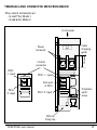
TERMINALS AND CONNECTOR SEEN FROM FRONT PANEL
Power terminals:
1 and 3: controlled phase
2 and 4: direct phase
Nominal
voltage and
current
2
1
240 V / 25 A
EUROTHERM
TE10S PDSIO
ε
Red LED:
fault detected
Green LED:
control signal
present
FAULT
1 2
7
3 4
5
3
4
Plug-in
control
connector
Control terminals:
PDSIO Mode 1:
5: Signal +
7: 0 V
PDSIO Mode 2:
5: Signal +
6: 0 V
Protective
earth
Example showing PDSIO Mode 1 front panel
14
TE10S/PDSIO User Manual