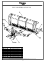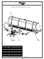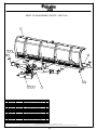
1
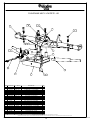
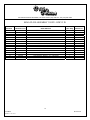
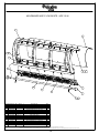
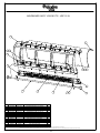
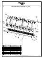
212 North Evans Road Evansdale, Iowa 50707 Phone (319) 236-7977; Fax (319) 236-7980
Owners Manual
J - PLOWS
Unit Serial Number: ________________
Record the MODEL and SERIAL NUMBER of equipment for parts ordering information.
PURCHASED FROM:
DATE:
MODEL:
SERIAL NUMBER:
212 North Evans Road Evansdale, Iowa 50707 Phone (319) 236-7977; Fax (319) 236-7980
WARRANTY POLICY
Viking Cives, USA warrants products of its manufacture against defects in workmanship and material for a period of one year, from the
date of shipment to the customer. In consequence of this warranty, any component part or parts of such products proving defective within the above
specified time will be repaired or replaced F.O.B. factory. Providing such parts are returned, transportation prepaid, to the factory and found
defective by Viking Cives, USA.
This warranty will not apply to any product which has been repaired or altered outside of Viking Cives, USA factory in any way, so as in
Viking Cives, USA judgement, to affect its stability or reliability, nor which has been subject to misuse or accident.
The obligations of Viking Cives, USA under this warranty are limited to the replacement of defective parts. Such obligations are
exclusive and in lieu of all other remedies, warranties, guarantees of liabilities, expressed or implied, with respect to each product delivered,
hereunder, arising by law or otherwise (including without limitation any obligation or liability by Viking Cives, USA arising from negligence or
with respect to fitness, merchantability, loss of use, revenue, or profit, or consequential damages or injuries).
This limited warranty shall not be extended, altered, or varied except by a written instrument signed by Viking Cives, USA.
Viking Cives, USA assumes no responsibility for engines, electrical equipment or any other equipment and accessories not manufactured
by Viking Cives, USA beyond the warranty of the manufacturer of such equipment of accessories.
All warranty work done on Viking Cives, USA equipment must have prior authorization from Viking Cives, USA along with a “Return
Goods Authorization” number. All labor and parts issued by user for Viking Cives, USA warranty without an authorization number and a signed
authorization warranty form will be at the users own cost.
ORDERING PARTS
Delays and errors can be eliminated when ordering instructions are followed correctly.
1.
Place orders direct with Viking-Cives Group/nearest dealer.
2.
State Company name, address, and postal/zip code.
3.
Give the exact model and serial number of the equipment/unit (stamped on the unit identification plate.)
4.
Furnish part number, description and quantities required. Note: An alpha designation in the Item ID column indicates a sub-component
for that parent item. When placing parts orders reference the parent item to receive a complete assembly. Individual items can be
ordered separately if required by ordering the alpha designated item number.
5.
Print or type order clearly.
6.
Give specific shipping instructions.
VIKING-CIVES (USA) – RR2, Box 36-1/2; Harrisville, New York 13648; (315) 543-2321, (315) 543-2366 Fax
VIKING-CIVES (USA) Midwest Division – 212 North Evans Road; Evansdale, Iowa 50707; (319) 236-7977, (319) 236-7980 Fax
VIKING-CIVES LTD. – RR4, Box 1120; Mount Forest, Ontario, Canada N0G 2L0; (519) 323-4433, (519) 323-4608 Fax
2
jplow092105
FORM 1-1.121.152-1
Revision 05
212 North Evans Road Evansdale, Iowa 50707 Phone (319) 236-7977; Fax (319) 236-7980
WARRANTY REQUEST PROCEDURE
All repairs considered for warranty that are performed outside of Viking Cives, USA; require prior written authorization from Viking
Cives, USA. Failure to obtain written warranty authorization prior to repairs may result in the rejection of the warranty claim. To obtain
warranty consideration one must provide all required Viking Cives, USA with unit information including date of manufacture and serial
numbers. In most cases this information is easily obtained from the “Shipped Unit Tag” (located in most cases inside the driver’s side door)
and/or individual unit serial tag.
(A) To obtain Parts Warranty Consideration:
(1) Contact Viking Cives, USA customer service to obtain a Return Goods Authorization (RGA) number. Any product
arriving at Viking Cives, USA without a RGA number will be rejected and returned to the sender at his or her own
expense.
(2) Goods are to be shipped prepaid to Viking Cives, USA in Evansdale, Iowa. All items should be clearly marked with
the appropriate RGA number.
(3) When a replacement item is shipped to replace a defective part for warranty consideration the following additional steps
will occur:
a) An invoice will be generated for the value of the replacement item(s).
b) The defective part(s) must be returned (prepaid) to Viking Cives, USA.
c) Upon receiving the defective part(s) Viking Cives, USA will issue and process a Discrepant Material Report
(DMR). Once the evaluation of the DMR report is complete and the parts are deemed warranty, a credit will
be issued against the outstanding invoice. If the part(s) are deemed Non-warranty the invoice will
remain outstanding to be paid to Viking Cives, USA. Any part(s) to be returned to the customer will be at
his or her own expense.
(B) To obtain Labor Parts Repair Warranty Consideration:
In the event that repairs are required outside of Viking Cives, USA facility that may be considered for warranty the following steps
must occur. Notification of Viking Cives, USA customer service must take place prior to the start of any repairs.
(1) Contact Viking Cives, USA customer service to obtain a Warranty Claim Form (WCF) and warranty authorization
number.
(2) Fill out all required WCF information and fax or mail the completed form to Viking Cives, USA, attention Customer
Service Department.
(3) Once the WCF report has been reviewed warranty authorization will be granted or denied. NOTE: Viking Cives, USA
warranty labor rates will apply unless specifically determined otherwise. Any part(s) involved in a WCF request
must follow the Parts Warranty Consideration procedures.
For Customer Service and/or Parts requests please contact:
Craig LaRue – ([email protected])
Ph. (319) 236-7977; Fax (319) 236-7980
3
jplow092105
FORM 1-1.121.152-1
Revision 05
212 North Evans Road Evansdale, Iowa 50707 Phone (319) 236-7977; Fax (319) 236-7980
TABLE OF CONTENTS
DESCRIPTION
WARRANTY/ORDERING INFORMATION
WARRANTY REQUEST PROCEDURE
INTRODUCTION
PERIODIC MAINTENANCE INSPECTION
DAILY INSPECTION AND LUBRICATION
GENERAL OPERATING INSTRUCTIONS
REGISTRATION/WARRANTY/SAFETY
INSTALLATION
OPERATION
MAINTENANCE
PAGE NO
2
3
5
5
5
6
7
8
9
10
PARTS
PUSHFRAME ASSEMBLY PARTS
12
DRAWING OF PUSHFRAME ASSEMBLY
3910 PLOW ASSEMBLY
DRAWING OF 3910 PLOW ASSEMBLY
3911 PLOW ASSEMBLY
DRAWING OF 3911 PLOW ASSEMBLY
3912 PLOW ASSEMBLY
DRAWING OF 3912 PLOW ASSEMBLY
3910 MOLDBOARD ASSEMBLY
DRAWING OF 3910 MOLDBAORD ASMBLY
3911 MOLDBAORD ASSEMBLY
DRAWING OF 3911 MOLDBOARD ASMBLY
3912 MOLDBOARD ASSEMBLY
DRAWING OF 3912 MOLDBOARD ASMBLY
13
14
15
16
17
18
19
20
21
22
23
24
25
4
jplow092105
FORM 1-1.121.152-1
Revision 05
212 North Evans Road Evansdale, Iowa 50707 Phone (319) 236-7977; Fax (319) 236-7980
INTRODUCTION
This instruction/parts manual has operation and maintenance information for the Viking-Cives (insert equipment Type).
It has been prepared to familiarize you with the design features of the unit, and to instruct you in its proper operation and
maintenance.
Read this manual carefully before you operate and/or service your (insert equipment Type). Remember that you’re
working with heavy equipment that can injure you or someone else. You can help lessen the chance of injury by following the
procedures in this manual, carefully.
DANGER: If incorrectly used, this equipment can cause severe injury. Your chance of injury can be greatly reduced
by following all caution/warning decal notifications. All decals must be kept clean and complete. Replace any decals that are
unreadable. Decals may be purchased directly from Viking-Cives Group and/or the nearest authorized dealer. All Operator/Service
people should review this manual carefully and become familiar with its contents. If anyone else beside you operates or services
this equipment, make sure they read this manual and are instructed to follow the safety procedures related to this
equipment.
PERIODIC MAINTENANCE INSPECTION
DAILY INSPECTION AND LUBRICATION
Daily inspection along with periodic preventive maintenance will reduce the chance of any major repairs and down time
during equipment use.
1.
2.
3.
4.
5.
6.
7.
8.
Check the fluid level in the hydraulic oil reservoir. If the sight indicates low oil level, add the appropriate amount of the
specified hydraulic fluid. Cold Weather Operation: All equipment is designed to operate with hydraulic oil minimally
warm. During cold weather conditions, it is recommended that the truck be run at idle with the pump engaged and
circulating the oil through the system before operating equipment.
Grease all required components:
- All plow harness sheave nipples.
- All pump drive shaft nipples.
- Front and Rear tower sheave swivel blocks.
- Wing extension arm nipples.
- Front and Rear tower guide tracks.
- All front harness pivot points.
Check all components for loose and/or missing fasteners, if required tighten and/or replace.
Visually inspect all battery terminals and electrical connections, wires, switches, etc. for signs of corrosion, wear, loose
and/or broken connections, etc. At the beginning of each shift review all lighting accessories to ensure proper working
conditions, immediately replace any broken or non-functioning bulbs and/or lenses.
Visually inspect all hydraulic connections and hoses for cracks and/or leaks.
Check all cables, chains and sheaves for excessive wear or damage.
Visually inspect plow and wing units. Check cutting edges and wear shoes. If cutting edge has excessive wear remove and
rotate, or if required replace. CAUTION: Do not allow cutting edge to wear down to mounting angle. Any wear to the
mounting angle may affect the operation and safety of the equipment. Replacement is costly.
At the beginning of each shift visually inspect all caution and warning decals. All decals should be complete and legible.
If decals are not legible, clean them. If cleaning the decals does not make them legible, install new decals.
5
jplow092105
FORM 1-1.121.152-1
Revision 05
212 North Evans Road Evansdale, Iowa 50707 Phone (319) 236-7977; Fax (319) 236-7980
GENERAL OPERATING INSTRUCTIONS
1.
2.
3.
The operator should familiarize himself with all equipment prior to operation. The in cabs controls are placed at a
comfortable reach of the operator, with an allowable amount of adjustment. If necessary, the controls can be adjusted for
either driver or passenger use.
Before putting any equipment into use, check for any worn, damaged or loose components, if necessary repair or replace.
Listen for any unusual sounds, if necessary repair and/or replace worn or damaged parts.
Before operating any equipment be sure to read and fully understand all caution and safety warnings. Familiarize yourself
and others with all caution/warning labels and their locations. Make sure all labels are complete and legible. Replace any
labels that have become unreadable and/or missing. Replacement labels can be purchased directly from Viking-Cives
Group and/or the nearest authorized dealer.
6
jplow092105
FORM 1-1.121.152-1
Revision 05
212 North Evans Road Evansdale, Iowa 50707 Phone (319) 236-7977; Fax (319) 236-7980
REGISTRATION OF EQUIPMENT AND WARRANTY INFORMATION
Report any damage to equipment at once to Viking Cives, USA. You should also register your equipment with Viking
Cives, USA, by filing out a warranty certificate and registration card and returning them to Viking Cives, USA. The warranty
period becomes effective upon date of delivery of equipment unless other arrangements have been made with a Distributor or
Viking Cives, USA. The information required to register the equipment may be found on the serial number tag secured to the
equipment.
A WORD ABOUT SAFETY:
The equipment described in this manual is normally being operated in adverse winter conditions with bad weather, snow and ice. Due
to these adverse operating conditions it is important that you the operator use good safety practices at all time to protect yourself, coworkers and others when using the equipment.
It is not practical or possible to warn you about all the hazards associated with the operation and maintenance of this equipment. You
should always use your own good judgment supplemented with the information found on the safety decals, instructions in this manual,
your employer’s safety programs, safety codes, local, state/provincial, and federal laws, rules and regulations.
When operating/performing maintenance on this equipment, trouble shooting equipment operations and loading or unloading the
sanders/spreaders with material observe & obey all safety decals on the equipment and warnings listed in the manual. Failure to do
this could result in serious injury or death to you or others.
Remember at all times that as the operator you are responsible for the safe operation of this equipment and responsible for the safety
of others. Good safety practices not only protect you but also protect the people around you.
7
jplow092105
FORM 1-1.121.152-1
Revision 05
212 North Evans Road Evansdale, Iowa 50707 Phone (319) 236-7977; Fax (319) 236-7980
INSTALLATION
TO CONNECT UNIT TO PRIME MOVER
During the initial installation of the plow to the vehicle, some adjustments will be necessary to insure proper operation of the
plow and trip mechanisms. NOTE: When plow is being raised, lowered or reversed – stand clear!
1.
2.
Set plow unit on level surface with the moldboard in the bulldoze position; adjust drive height to approximately 21” as
shown in figure 1.
Drive the prime mover into position. Connect the plow drive frame to the vehicle push harness. NEVER stand
between the prime mover and the plow drive frame when the vehicle is being moved into position. Before
connecting the drive frame to the push harness, shut the vehicle engine down and make sure that the auxiliary brake is
engaged.
TO CONNECT HYDRAULICS FOR REVERSING CYLINDERS
Connect the hydraulic hoses leading from the cushion valve located on the plow drive frame to the quick disconnect couplers
located on the prime mover. NOTE: Normally one hose will have a male quick disconnect hose end and the other will have a female
quick disconnect hose end. This prevents the hoses from being coupled incorrectly. Also when the hoses are disconnected from the
prime mover this allows for them to be coupled together to prevent contamination from entering into the hydraulic system.
NOTE: Plow lift and power reverse functions should be thoroughly tested BEFORE operating the plow in a working
situation.
8
jplow092105
FORM 1-1.121.152-1
Revision 05
212 North Evans Road Evansdale, Iowa 50707 Phone (319) 236-7977; Fax (319) 236-7980
OPERATION
When all conditions of installation have been met, the plow is ready to operate. NOTE: Always lift the plow before
reversing. The levers for controlling the plow lift and reverse functions are located in the cab of the prime mover.
TO LIFT THE PLOW
The plow lift lever activates a three-position valve. Normally to raise the plow, pull the plow lift lever. When you release
the lever the valve will return to a neutral hold position and the plow will remain in that position. To lower the plow, push the plow
lift lever. When you release the lever, the valve will return to a neutral hold position. NOTE: For plows with this lift valve
arrangement, it is necessary to hold the plow lift lever in the down position for a few moments while plowing to allow the plow to
seek its lowest level. After this has been accomplished you can release the lever and the plow will be properly set to follow the
contour of the plowing surface. However, some units are equipped with a three-position plow lift valve with a detent in the down
position. This valve will lock in a float position when the plow is lowered. The plow will then automatically seek its lowest level
allowing it to follow the contour of the plowing surface.
TO REVERSE THE PLOW
Normally the plow reverse lever activates a three-position valve. If you push or pull this lever, the plow will reverse to the
right or left accordingly. When you release the lever the valve will shift to a neutral hold position. Therefore, you have an infinite
variety of plowing angle at your disposal.
TO ADJUST THE ATTACK ANGLE:
The cutting edge angle is preset a 105° (± 5°) when the plow is driven at 19” (± 1”).
NEVER stand between the vehicle and the drive frame when
the vehicle is being moved into position. Before connecting the
drive frame to the push frame, shut the engine down and make
sure that the auxiliary brake is engaged.
TO INSTALL THE LIFT CHAIN
With the plow lift arm fully collapsed, put a few links of the lift chain “A” through the grab link on the push frame lift arm.
Leave some slack to allow plow to follow contour of road, but also insure adequate carrying height with the lifting device ram
extended. The plow drive frame should be parallel (level) with the ground in the carry position.
CAUTION! Do not take too short grab on the lift chain. Damage can occur (grab link can bend or chain can break) if the stroke of
the lift ram exceeds the travel length of the chain. When properly positioned, the tree “legs” of chain will be taut with the front chain
being slightly tighter.
9
jplow092105
FORM 1-1.121.152-1
Revision 05
212 North Evans Road Evansdale, Iowa 50707 Phone (319) 236-7977; Fax (319) 236-7980
MAINTENANCE
In preparation for the snowplowing season and after every eight (8) hours of operation, a visual equipment inspection must
be performed. Look for any damaged components, bends, cracked welds, hydraulic leaks, etc. Inspect all fasteners; tighten any that
have loosened and replace any that are damaged. Check all hydraulic hoses for cuts, cracks and/or leaks. Check plow lift cable(s) for
loose clamps and frays. Immediately replace frayed cables. On plows with push frame mounted shoes, check all shoe mounting
bolts for tightness and/or proper adjustment. Correct shoe height setup is critical for plow operation and performance.
Periodically during plowing, stop to inspect plow cutting edges and moldboard/push frame shoes for wear. At the first sign
of excessive wear, discard and replace with new parts.
When the plow is disconnected from the prime mover, be sure to couple the hydraulic hoses together, to prevent damage to the quick
disconnect hose ends and to help prevent the introduction of foreign material into the hydraulic system.
TO REMOVE A TORSION SPRING
Lay the plow on its face. Loosen the spring tension bolts. Hold the spring in a slightly compressed state. Remove the nut,
washer and spring keeper assembly from all the springs. The springs will now be in a completely free, or unloaded state.
Remove the curb shoe from the end of the plow by unbolting it from the tubing (the pivot for the trip edge). Slide the tubing
out of the plow. As it passes through each spring, remove the spring. This can be done by slightly twisting and rotating the spring on
the bias while removing it. It will come out between the moldboard backer angle and the trip edge backer angle.
LUBRICATION SCHEDULE
After every 8 hours of operation, the following points must be lubricated:
1.
2.
3.
MAIN PIVOT PIN – Apply Texaco Marfax heavy duty #2 (or equal) with grease gun to fitting at pivot pin.
CASTER TUBE ASSEMBLY – Apply Texaco heavy duty #2 (or equal) with a grease gun to all fittings. There are (2)
grease fittings located on each caster assembly.
CASTER ADJUSTMENT ROD – Apply SAE #30 oil with an oil can to all friction points.
10
jplow092105
FORM 1-1.121.152-1
Revision 05
212 North Evans Road Evansdale, Iowa 50707 Phone (319) 236-7977; Fax (319) 236-7980
11
jplow092105
FORM 1-1.121.152-1
Revision 05
212 North Evans Road Evansdale, Iowa 50707 Phone (319) 236-7977; Fax (319) 236-7980
PUSHFRAME ASS'Y VCM PRTE-HD
ITEM ID
1
2
3
4
5
6
7
8
9
10
11
12
13
14
15
16
17
18
19
20
21
22
ITEM NO
202100909
202100923
20540302
201501206
202100942
202101077
202101078
202100938
20530031
81023C-V
281028
215367
281066
3SK3610
3SK3495
281007B
3SK3811
3SK3497
281014A
3SK3661
233626
280577
DESCRIPTION
RAM REVERSE A-FRAME WELD’T
RAM REVERSE TRUSS FRAME WELD’T
CYLINDER SA 3.5 X 16.125 FRINK
HOSE KIT FRK TE-HDP
A-FRAME RETAINER PLT
BRACE BAR
SHIM PLATE
PIN 1.250 DIA X 5.500 WELD’T
VALUE CUSHION DXV-50-2000
BOLT HEX 1 ¼ X 6 UNC ZINC
BOLT HEX 1 ¼ X 3 UNC ZINC
BOLT HEX ¾ X 3 ½ UNC ZINC
BOLT HEX ¾ X 3 UNC ZINC
BOLT HEX ½ X 1 ¼ UNC ZINC
BOLT HEX 5/16 X 2 ½ UNC ZINC
NUT HEX TOPLOCK 1 ¼” UNC ZINC
NUT HEX TOPLOCK ¾” UNC ZINC
NUT HEX TOPLOCK 5/16” UNC ZINC
LOCKWASHER SPLIT 1 ¼ ZINC
FLATWASHER SAE ½ ZINC
LOCKWASHER SPLIT ½ ZINC
GREASE FITTING 1/8 NPT STR
QTY REQ
1
1
2
1
1
1
1
2
1
2
1
2
2
2
2
2
4
2
1
2
2
1
OPTIONAL
12
jplow092105
FORM 1-1.121.152-1
Revision 05
212 NORTH EVANS ROAD, EVANSDALE, IOWA 50707 (319)236-7977 PH (319)236-7980 FX
PUSHFRAME ASS'Y VCM PRTE - HD
17
2
13
19
11
6
10
20
21
16
14
8
18
15
22
7
5
4
3
9
1
ITEM DRAWING NO. ALT. ITEM NO.
1
202100909
2
202100923
0051-4-140
3
20540302
0003-1-89
4
201501206
5
202100942
0051-5-265
6
202101077
103-7628
7
202101078
103-7629
8
202100938
0051-1-24
9
20530031
80244D
10
81023C-C
81023C
11
281028
12
215367
13
281066
14
3SK3610
15
3SK3495
16
281007B
80999D
17
3SK3811
18
3SK3497
HH-00340-017
19
281014A
81015B
20
3SK3661
21
233626
81080
22
280577
80577
DESCRIPTION
RAM REVERSE A-FRAME WELD'T
RAM REVERSE TRUSS FRAME WELD'T
CYLINDER SA 3.5 X 16.125 FRINK
HOSE KIT FRK TE-HDP
A-FRAME RETAINER PLT
BRACE BAR
SHIM PLATE
PIN 1.250 DIA X 5.500 WELD'T
VALVE CUSHION DXV-50-2000
BOLT HEX 1 1/4 X 6 UNC ZINC
BOLT HEX 1 1/4 X 3 UNC ZINC
BOLT HEX 3/4 X 3 1/2 UNC ZINC
BOLT HEX 3/4 X 3 UNC ZINC
BOLT HEX 1/2 X 2 UNC ZINC
BOLT HEX 5/16 X 2 1/2 UNC ZINC
NUT HEX TOPLOCK 1 1/4" UNC ZINC
NUT HEX TOPLOCK 3/4" UNC ZINC
NUT HEX TOPLOCK 5/16" UNC ZINC
LOCKWASHER SPLIT 1 1/4 ZINC
FLATWASHER SAE 1/2 ZINC
LOCKWASHER SPLIT 1/2 ZINC
GREASE FITTING 1/8 NPT STR
12
17
QTY
1
1
2
1
1
1
1
2
1
2
1
2
2
2
2
2
4
2
1
2
2
1
EQUIPMENT MAY NOT BE EXACTLY AS SHOWN. SOME COMPONENTS MAY BE OPTIONAL
TO MAINTAIN OUR ON-GOING PRODUCT AND DEVELOPMENT IMPROVEMENT PROGRAM, VIKING-CIVES RESERVES THE RIGHT TO CHANGE EQUIPMENT & SPECIFICATION WITHOUT NOTICE.
13
This Owner's Manual File is Contained Within
PUSH FRAME ASS'Y 202101002
212 North Evans Road Evansdale, Iowa 50707 Phone (319) 236-7977; Fax (319) 236-7980
S8260: PLOW ASSEMBLY 3910TE - HDP 12 IN
ITEM ID
1
2
3
4
5
6
7
8
9
10
11
12
13
14
15
16
DRAWING NO
202101002
202101022
280005E
3SK3410
200900211
281022A
2N81074C
2181010
237278
3SK3781
3SK3860
281013A
3SK3450
2002505
2002750
DESCRIPTION
PUSHFRAME ASS'Y VCL PRTE-HD
MOLDBOARD ASS'Y 3910TE-HDP 12 IN
CUTTING EDGE ¾ X 6 X 120
PIN 1” X 4”
BOLT DRILLED 1.500 X 3.813
BOLT HEX 1 X 4 ½ UNC ZINC
BOLT CARRIAGE 5/8 X 2 ½ UNC ZINC
NUT HEX SLOTTED 1 ½ UNC ZINC
NUT HEX TOPLOCK 1” UNC ZINC
NUT HEX TOPLOCKS 5/8” UNC ZINC
FLATWASHER USS 1 ½ ZINC
FLATWASHER SAE 1” ZINC
COTTER PIN ¼ X 2 ½ ZINC
RUBBER DEFLECTOR INSTL KIT – 10 FT
UQH SWIVEL WELD’T 30 ½ CENTERS
PUSHLUG SWIVEL WELD’T 30 ½ CENTERS
QTY REQ
1
1
1
4
1
2
12
1
2
12
1
4
5
*
*
*
OPTIONAL
14
09700052
FORM 1-1.121.152-1
Revision 05
212 NORTH EVANS ROAD, EVANSDALE, IOWA 50707 (319)236-7977 PH (319)236-7980 FX
S8260: PLOW ASSEMBLY 3910TE-HDP 12 IN
2
12
9
13
4
6
3
10
5
ITEM DRAWING NO. ALT. ITEM NO.
1
202101002
2
202101022
3
280005E
4
3SK3410
5
200900211
002751-2
6
281022A
81022
7
2N81074C
81105A
8
2181010
81010
9
237278
10
SK3781
11
3SK3860
12
281013A
81013A
13
80508A
3SK3450
14
15
2002505
16
2002750
8
11
13
7
1
DESCRIPTION
PUSHFRAME ASS'Y VCL PRTE-HD
MOLDBOARD ASS'Y 3910TE-HDP 12 IN
CUTTING EDGE 3/4 X 6 X 120
PIN 1" X 4"
BOLT DRILLED 1.500 X 3.813
BOLT HEX 1 X 4 1/2 UNC ZINC
BOLT CARRIAGE 5/8 X 2 1/2 UNC ZINC
NUT HEX SLOTTED 1 1/2 UNC ZINC
NUT HEX TOPLOCK 1" UNC ZINC
NUT HEX TOPLOCK 5/8" UNC ZINC
FLATWASHER USS 1 1/2 ZINC
FLATWASHER SAE 1" ZINC
COTTER PIN 1/4 X 2 1/2 ZINC
RUBBER DEFLECTOR INSTL KIT - 10 FT
UQH SWIVEL WELD'T 30 1/2 CENTERS
PUSHLUG SWIVEL WELD'T 30 1/2 CENTERS
QTY
1
1
1
4
1
2
12
1
2
12
1
4
5
*
*
*
EQUIPMENT MAY NOT BE EXACTLY AS SHOWN. SOME COMPONENTS MAY BE OPTIONAL
TO MAINTAIN OUR ON-GOING PRODUCT AND DEVELOPMENT IMPROVEMENT PROGRAM, VIKING-CIVES RESERVES THE RIGHT TO CHANGE EQUIPMENT & SPECIFICATION WITHOUT NOTICE.
21
This Owner's Manual File is Contained Within
3910 PLOW ASSEMBLY.idw
212 North Evans Road Evansdale, Iowa 50707 Phone (319) 236-7977; Fax (319) 236-7980
S8265: PLOW ASSEMBLY 3911TE - HDP 12 IN
ITEM ID
1
2
3
4
5
6
7
8
9
10
11
12
13
14
15
16
DRAWING NO
202101002
202101004
280028B
3SK3410
200900211
281022A
2N81074C
2181010
237278
3SK3781
3SK3860
281013A
3SK3450
2002505
2002750
DESCRIPTION
PUSHFRAME ASS'Y VCL PRTE-HD
MOLDBOARD ASS'Y VCL 3911TE-HDP 12IN
CUTTING EDGE ¾ X 6 X 132
PIN 1” X 4”
BOLT DRILLED 1.500 X 3.813
BOLT HEX 1 X 4 ½ UNC ZINC
BOLT CARRIAGE 5/8 X 2 ½ UNC ZINC
NUT HEX SLOTTED 1 ½ UNC ZINC
NUT HEX TOPLOCK 1” UNC ZINC
NUT HEX TOPLOCK 5/8” UNC ZINC
FLATWASHER USS 1 ½ ZINC
FLATWASHER SAE 1” ZINC
COTTER PIN ¼ X 2 ½ ZINC
RUBBER DEFLECTOR INSTL KIT – 11 FT
UQH SWIVEL WELD’T 30 ½ CENTERS
PUSHLUG SWIVEL WELD’T 30 ½ CENTERS
QTY REQ
1
1
1
4
1
2
13
1
2
13
1
4
5
*
*
*
OPTIONAL
16
jplow092105
FORM 1-1.121.152-1
Revision 05
212 NORTH EVANS ROAD, EVANSDALE, IOWA 50707 (319)236-7977 PH (319)236-7980 FX
S8265: PLOW ASSEMBLY 3911TE - HDP 12 IN
2
12
13
9
6
4
3
5
ITEM DRAWING NO. ALT. ITEM NO.
1
202101002
2
202101004
3
280028B
4
3SK3410
5
200900211
002751-2
6
281022A
81022
7
2N81074C
81105A
8
2181010
81010
9
237278
10
SK3781
11
3SK3860
12
281013A
81013A
13
80508A
3SK3450
14
15
2002505
16
2002750
8
11
13
10
1
DESCRIPTION
PUSHFRAME ASS'Y VCL PRTE-HD
MOLDBOARD ASS'Y VCL 3911TE-HDP 12IN
CUTTING EDGE 3/4 X 6 X 132
PIN 1" X 4"
BOLT DRILLED 1.500 X 3.813
BOLT HEX 1 X 4 1/2 UNC ZINC
BOLT CARRIAGE 5/8 X 2 1/2 UNC ZINC
NUT HEX SLOTTED 1 1/2 UNC ZINC
NUT HEX TOPLOCK 1" UNC ZINC
NUT HEX TOPLOCK 5/8" UNC ZINC
FLATWASHER USS 1 1/2 ZINC
FLATWASHER SAE 1" ZINC
COTTER PIN 1/4 X 2 1/2 ZINC
RUBBER DEFLECTOR INSTL KIT - 11 FT
UQH SWIVEL WELD'T 30 1/2 CENTERS
PUSHLUG SWIVEL WELD'T 30 1/2 CENTERS
7
QTY
1
1
1
4
1
2
13
1
2
13
1
4
5
*
*
*
EQUIPMENT MAY NOT BE EXACTLY AS SHOWN. SOME COMPONENTS MAY BE OPTIONAL
TO MAINTAIN OUR ON-GOING PRODUCT AND DEVELOPMENT IMPROVEMENT PROGRAM, VIKING-CIVES RESERVES THE RIGHT TO CHANGE EQUIPMENT & SPECIFICATION WITHOUT NOTICE.
23
This Owner's Manual File is Contained Within
3911 PLOW ASSEMBLY.idw
212 North Evans Road Evansdale, Iowa 50707 Phone (319) 236-7977; Fax (319) 236-7980
S8270: PLOW ASSEMBLY 3912TE - HDP 12 IN
ITEM ID
1
2
3
4
5
6
7
8
9
10
11
12
13
14
15
16
ITEM NO
202101002
202101016
280014b
3SK3410
200900211
281022A
2N81074C
2181010
237278
3SK3781
3SK3860
281013A
3SK3450
2002505
2002750
DESCRIPTION
PUSHFRAME ASS'Y VCL PRTE-HD
MOLDBOARD ASS'Y VCL 3912TE-HDP 12IN
CUTTING EDGE TP ¾ X 6 X 144
PIN 1” X 4”
BOLT DRILLED 1.500 X 3.813
BOLT HEX 1 X 4 ½ UNC ZINC
BOLT CARRIAGE 5/8 X 2 ½ UNC ZINC
NUT HEX SLOTTED 1 ½ UNC ZINC
NUT HEX TOPLOCK 1” UNC ZINC
NUT HEX TOPLLOCK 5/8” UNC ZINC
FLATWASHER USS 1 ½ ZINC
FLATWASHER SAE 1” ZINC
COTTER PIN ¼ X ½ ZINC
RUBBER DEFLECTOR INSTL KIT – 12 FT
UQH SWIVEL WELD’T 30 ½ CENTERS
PUSHLUG SWIVEL WELD’T 30 ½ CENTERS
QTY REQ
1
1
1
4
1
2
14
1
2
14
1
4
5
*
*
*
OPTIONAL
18
jplow092105
FORM 1-1.121.152-1
Revision 05
212 NORTH EVANS ROAD, EVANSDALE, IOWA 50707 (319)236-7977 PH (319)236-7980 FX
S8270: PLOW ASSEMBLY 3912TE - HDP 12 IN
2
12
13
9
6
3
4
10
5
ITEM DRAWING NO. ALT. ITEM NO.
1
202101002
2
202101016
3
280014B
4
3SK3410
5
200900211
002751-2
6
281022A
81022
7
2N81074C
81105A
8
2181010
81010
9
237278
10
SK3781
11
3SK3860
12
281013A
81013A
13
80508A
3SK3450
14
15
2002505
16
2002750
8
11
13
7
1
DESCRIPTION
PUSHFRAME ASS'Y VCL PRTE-HD
MOLDBOARD ASS'Y VCL 3912TE-HDP 12IN
CUTTING EDGE TP 3/4 X 6 X 144
PIN 1" X 4"
BOLT DRILLED 1.500 X 3.813
BOLT HEX 1 X 4 1/2 UNC ZINC
BOLT CARRIAGE 5/8 X 2 1/2 UNC ZINC
NUT HEX SLOTTED 1 1/2 UNC ZINC
NUT HEX TOPLOCK 1" UNC ZINC
NUT HEX TOPLOCK 5/8" UNC ZINC
FLATWASHER USS 1 1/2 ZINC
FLATWASHER SAE 1" ZINC
COTTER PIN 1/4 X 2 1/2 ZINC
RUBBER DEFLECTOR INSTL KIT - 12 FT
UQH SWIVEL WELD'T 30 1/2 CENTERS
PUSHLUG SWIVEL WELD'T 30 1/2 CENTERS
QTY
1
1
1
4
1
2
14
1
2
14
1
4
5
*
*
*
EQUIPMENT MAY NOT BE EXACTLY AS SHOWN. SOME COMPONENTS MAY BE OPTIONAL
TO MAINTAIN OUR ON-GOING PRODUCT AND DEVELOPMENT IMPROVEMENT PROGRAM, VIKING-CIVES RESERVES THE RIGHT TO CHANGE EQUIPMENT & SPECIFICATION WITHOUT NOTICE.
25
This Owner's Manual File is Contained Within
3912 PLOW ASSEMBLY.idw
212 North Evans Road Evansdale, Iowa 50707 Phone (319) 236-7977; Fax (319) 236-7980
MOLDBOARD ASS’Y VCM 3910TE - HDP 12 IN
ITEM ID
1
2
3
4
5
6
7
8
9
10
11
12
13
14
15
ITEM NO
202100952
202101019
202101023
202101024
202100966
20580038
202100989
202100969
202100957
3SK3722
3SK3711
221834
3SK3781
3SK3785
3SK3772
DESCRIPTION
MOLDBOARD WELD'T VCL 3910TE-HDP
TRIP EDGE WELD’T CTR 10/12FT 12IN
TRIP EDGE WELD’T RTH 10FT 12IN
TRIP EDGE WELD’T LTH 10FT 12IN
TRIP EDGE MTG TUBE 10FT TE-HD
SPRING TORSION FRINK 39 SERIES
TRIP SPRING RETAINER CLAMP
CURB SHOE WELD’T
MOLDBOARD SKIN POLY 3910TE-HDP
BOLT HEX 5/8 X 3 ½ UNC ZINC
BOLT HEX 5/8 X 3 UNC ZINC
BOLT CARRIAGE 5/8 X 2 UNC ZINC
NUT HEX TOPLOCK 5/8” UNC ZINC
NUT HEX 5/8 UNC ZINC
LOCKWASHER SPLIT 5/8 ZINC
QTY REQ
1
1
1
1
1
6
6
2
1
6
2
22
8
22
22
OPTIONAL
20
jplow092105
FORM 1-1.121.152-1
Revision 05
212 NORTH EVANS ROAD, EVANSDALE, IOWA 50707 (319)236-7977 PH (319)236-7980 FX
MOLDBOARD ASS'Y VCM 3910TE - HDP 12 IN
1
9
13
10
7
4
12
5
14
15
3
2
6
8
11
ITEM DRAWING NO. ALT. ITEM NO.
1
202100952
0051-4-95
2
202101019
3
202101023
4
202101024
5
202100966
6
20580038
0051-6-106
7
202100989
0051-5-525
8
202100969
0051-1-2
9
202100957
0051-5-216
10
3SK3722
11
3SK3711
12
221834
13
3SK3781
14
81069H
3SK3785
15
3SK3772
81070C
DESCRIPTION
MOLDBOARD WELD'T VCL 3910TE-HDP
TRIP EDGE WELD'T CTR 10/12FT 12IN
TRIP EDGE WELD'T RTH 10FT 12IN
TRIP EDGE WELD'T LTH 10FT 12IN
TRIP EDGE MTG TUBE 10FT TE-HD
SPRING TORSION FRINK 39 SERIES
TRIP SPRING RETAINER CLAMP
CURB SHOE WELD'T
MOLDBOARD SKIN POLY 3910TE-HDP
BOLT HEX 5/8 X 3 1/2 UNC ZINC
BOLT HEX 5/8 X 3 UNC ZINC
BOLT CARRIAGE 5/8 X 2 UNC ZINC
NUT HEX TOPLOCK 5/8" UNC ZINC
NUT HEX 5/8 UNC ZINC
LOCKWASHER SPLIT 5/8 ZINC
13
QTY
1
1
1
1
1
6
6
2
1
6
2
22
8
22
22
EQUIPMENT MAY NOT BE EXACTLY AS SHOWN. SOME COMPONENTS MAY BE OPTIONAL
TO MAINTAIN OUR ON-GOING PRODUCT AND DEVELOPMENT IMPROVEMENT PROGRAM, VIKING-CIVES RESERVES THE RIGHT TO CHANGE EQUIPMENT & SPECIFICATION WITHOUT NOTICE.
15
This Owner's Manual File is Contained Within
10' J-PLOW ASS'Y.idw
212 North Evans Road Evansdale, Iowa 50707 Phone (319) 236-7977; Fax (319) 236-7980
MOLDBOARD ASS’Y VCM 3911TE - HDP 12 IN
ITEM ID
1
2
3
4
5
6
7
8
9
10
11
12
13
14
15
ITEM NO
202100978
202100951
202100943
202100950
202100981
20580038
202100989
202100969
202100974
3SK3722
3SK3711
221834
3SK3781
3SK3785
3SK3772
DESCRIPTION
MOULDBOARD WELD'T 3911TE-HDP
TRIP EDGE WELD’T CTR 11FT 12IN
TRIP EDGE WELD’T RTH 11FT 12IN
TRIP EDGE WELD’T LTH 11FT 12IN
TRIP EDGE MTG TUBE 11FT TE-HD
SPRING TORSION FRINK 39 SERIES
TRIP SPRING RETAINER CLAMP
CURB SHOE WELD’T
MOLDBOARD SKIN POLY 3911TE-HDP
BOLT HEX 5/8 X 3 ½ UNC ZINC
BOLT HEX 5/8 X 3 UNC ZINC
BOLT CARRIAGE 5/8 X 2 UNC ZINC
NUT HEX TOPLOCK 5/8” UNC ZINC
NUT HEX 5/8 UNC ZINC
LOCKWASHER SPLIT 5/8 ZINC
QTY REQ
1
1
1
1
1
6
6
2
1
6
2
26
8
26
26
OPTIONAL
22
jplow092105
FORM 1-1.121.152-1
Revision 05
212 NORTH EVANS ROAD, EVANSDALE, IOWA 50707 (319)236-7977 PH (319)236-7980 FX
MOLDBOARD ASS'Y VCM 3911TE - HDP 12 IN
1
9
13
10
7
4
12
14
15
3
5
ITEM DRAWING NO. ALT. ITEM NO.
1
202100978
0051-4-89
2
202100951
0051-3-74
3
202100943
0051-3-73
4
202100950
0051-3-72
5
202100981
0051-5-32
6
20580038
0051-6-106
7
202100989
0051-5-525
8
202100969
0051-1-2
9
202100974
0051-5-171
10
3SK3722
11
3SK3711
12
221834
13
3SK3781
14
3SK3785
81069H
15
3SK3772
81070C
2
DESCRIPTION
MOULDBOARD WELD'T 3911TE-HDP
TRIP EDGE WELD'T CTR 11FT 12IN
TRIP EDGE WELD'T RTH 11FT 12IN
TRIP EDGE WELD'T LTH 11FT 12IN
TRIP EDGE MTG TUBE 11FT TE-HD
SPRING TORSION FRINK 39 SERIES
TRIP SPRING RETAINER CLAMP
CURB SHOE WELD'T
MOLDBOARD SKIN POLY 3911TE-HDP
BOLT HEX 5/8 X 3 1/2 UNC ZINC
BOLT HEX 5/8 X 3 UNC ZINC
BOLT CARRIAGE 5/8 X 2 UNC ZINC
NUT HEX TOPLOCK 5/8" UNC ZINC
NUT HEX 5/8 UNC ZINC
LOCKWASHER SPLIT 5/8 ZINC
6
13
11
8
QTY
1
1
1
1
1
6
6
2
1
6
2
26
8
26
26
EQUIPMENT MAY NOT BE EXACTLY AS SHOWN. SOME COMPONENTS MAY BE OPTIONAL
TO MAINTAIN OUR ON-GOING PRODUCT AND DEVELOPMENT IMPROVEMENT PROGRAM, VIKING-CIVES RESERVES THE RIGHT TO CHANGE EQUIPMENT & SPECIFICATION WITHOUT NOTICE.
17
This Owner's Manual File is Contained Within
11' J-PLOW ASS'Y.idw
212 North Evans Road Evansdale, Iowa 50707 Phone (319) 236-7977; Fax (319) 236-7980
MOLDBOARD ASS’Y VCM 3912TE - HDP 12 IN
ITEM ID
1
2
3
4
5
6
7
8
9
10
11
12
13
14
15
ITEM NO
202101005
202101019
202101018
202101020
202101017
20580038
202100989
202100969
202101015
3SK3722
3SK3711
221834
3SK3781
3SK3785
3SK3772
DESCRIPTION
MOLDBOARD WELD'T VCL 3912TE - HDP
TRIP EDGE WELD’T CTR 10/12FT 12IN
TRIP EDGE WELD’T RTH 12FT 12IN
TRIP EDGE WELD’T LTH 12FT 12IN
TRIP EDGE MTG TUBE 12FT TE-HD
SPRING TORSION FRINK 39 SERIES
TRIP SPRING RETAINER CLAMP
CURB SHOE WELD’T
MOLDBOARD SKIN POLY 3912TE-HDP
BOLT HEX 5/8 X 3 ½ UNC ZINC
BOLT HEX 5/8 X 3 UNC ZINC
BOLT CARRIAGE 5/8 X 2 UNC ZINC
NUT HEX TOPLOCK 5/8” UNC ZINC
NUT HEX 5/8 UNC ZINC
LOCKWASHER SPLIT 5/8 ZINC
QTY REQ
1
1
1
1
1
8
8
2
1
8
2
26
10
26
26
OPTIONAL
24
jplow092105
FORM 1-1.121.152-1
Revision 05
212 NORTH EVANS ROAD, EVANSDALE, IOWA 50707 (319)236-7977 PH (319)236-7980 FX
MOLDBOARD ASS'Y VCM 3912TE - HDP 12 IN
1
9
13
10
7
4
12
5
14
15
3
2
6
8
11
ITEM DRAWING NO. ALT. ITEM NO.
1
202101005
0051-4-96
2
202101019
3
202101018
4
202101020
5
202101017
6
20580038
0051-6-106
7
202100989
0051-5-525
8
202100969
0051-1-2
9
202101015
10
3SK3722
11
3SK3711
12
221834
13
SK3781
14
3SK3785
81069H
15
3SK3772
81070C
DESCRIPTION
MOLDBOARD WELD'T VCL 3912TE-HDP
TRIP EDGE WELD'T CTR 10/12FT 12IN
TRIP EDGE WELD'T RTH 12FT 12IN
TRIP EDGE WELD'T LTH 12FT 12IN
TRIP EDGE MTG TUBE 12 FT TE-HD
SPRING TORSION FRINK 39 SERIES
TRIP SPRING RETAINER CLAMP
CURB SHOE WELD'T
MOLDBOARD SKIN POLY 3912TE-HDP
BOLT HEX 5/8 X 3 1/2 UNC ZINC
BOLT HEX 5/8 X 3 UNC ZINC
BOLT CARRIAGE 5/8 X 2 UNC ZINC
NUT HEX TOPLOCK 5/8" UNC ZINC
NUT HEX 5/8 UNC ZINC
LOCKWASHER SPLIT 5/8 ZINC
13
QTY
1
1
1
1
1
8
8
2
1
8
2
26
10
26
26
EQUIPMENT MAY NOT BE EXACTLY AS SHOWN. SOME COMPONENTS MAY BE OPTIONAL
TO MAINTAIN OUR ON-GOING PRODUCT AND DEVELOPMENT IMPROVEMENT PROGRAM, VIKING-CIVES RESERVES THE RIGHT TO CHANGE EQUIPMENT & SPECIFICATION WITHOUT NOTICE.
19
This Owner's Manual File is Contained Within
12' J-PLOW ASS'Y.idw
212 North Evans Road Evansdale, Iowa 50707 Phone (319) 236-7977; Fax (319) 236-7980
Notes:
26
jplow092105
FORM 1-1.121.152-1
Revision 05