1
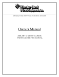
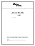
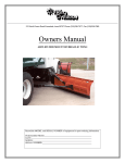
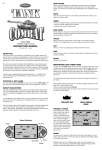
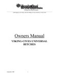
212 North Evans Road Evansdale, Iowa 50707 Phone (319) 236-7977 Fax (319) 236-7980
Owners Manual
DOUBLE FUNCTION PATROL WING
METRO 225
S7720
Unit Serial Number: ________________
212 North Evans Road Evansdale, Iowa 50707 Phone (319) 236-7977 Fax (319) 236-7980
WARRANTY POLICY
Viking Cives, USA warrants products of its manufacture against defects in workmanship and material for a period of one year, from the
date of shipment to the customer. In consequence of this warranty, any component part or parts of such products proving defective within the above
specified time will be repaired or replaced F.O.B. Factory. Providing such parts are returned, transportation prepaid, to the factory and found
defective by Viking Cives, USA.
This warranty will not apply to any product which has been repaired or altered outside of Viking Cives, USA factory in any way, so as in
Viking Cives, USA’s judgement, to affect its stability or reliability, nor which has been subject to misuse or accident.
The obligations of Viking Cives, USA under this warranty are limited to the replacement of defective parts. Such obligations are exclusive
and in lieu of all other remedies, warranties, guarantees of liabilities, expressed or implied, with respect to each product delivered. Here under,
arising by law or otherwise (including without limitation any obligation or liability by Viking Cives, USA arising from negligence or with respect to
fitness, merchantability, loss of use, revenue, or profit, or consequential damages or injuries).
This limited warranty shall not be extended, altered, or varied except by a written instrument signed by Viking Cives, USA.
Viking Cives, USA assumes no responsibility for engines, electrical equipment or any other equipment and accessories not manufactured
by Viking Cives, USA beyond the warranty of the manufacturer of such equipment of accessories.
All warranty work done on Viking Cives, USA equipment must have prior authorization from Viking Cives, USA along with a “Return
Goods Authorization” number. All labor and parts issued by user for Viking Cives, USA warranty without an authorization number and a signed
authorization warranty form will be at the users own cost.
ORDERING PARTS
Delays and errors can be eliminated when ordering instructions are followed correctly.
1.
Place orders direct with Viking-Cives/nearest dealer.
2.
State Company name, address, and postal/zip code.
3.
Give the exact model and serial number of the equipment/unit (stamped on the unit identification plate.)
4.
Furnish part number, description and quantities required.
5.
Print or type order clearly.
6.
Give specific shipping instructions.
VIKING-CIVES (USA) – RR2, Box 36-1/2; Harrisville, New York 13648; (315) 543-2321, (315) 543-2366 Fax
VIKING-CIVES (USA) Midwest Division – 212 North Evans Road; Evansdale, Iowa 50707; (319) 236-7977, (319) 236-7980 Fax
VIKING-CIVES LTD. – RR4, Box 1120; Mount Forest, Ontario, Canada N0G 2L0; (519) 323-4433, (519) 323-4608 Fax
2
MW225-3
REV DATE 2004
212 North Evans Road Evansdale, Iowa 50707 Phone (319) 236-7977 Fax (319) 236-7980
TABLE OF CONTENTS
DESCRIPTION
PAGE No.
Warranty policy / Ordering parts
Introduction
Periodic maintenance inspection
Daily inspection and lubrication
Operating instructions
Drawing of wing installation on truck
Drawing of dual arm MTG kit
Parts break down of wing installation on truck
Parts break down of dual arm MTG kit
Parts break down of DF patrol wing
Drawing of DF patrol wing
Drawing of mast assembly
Parts break down of mast assembly
Drawing of bracket assembly metro 3 point
Parts break down of bracket asb’y 3 point
Drawing of full trip hinge
Parts break down of full trip hinge
Drawing of upper arm assembly
Parts break down of upper arm assembly
Drawing of lower arm assembly
Parts break down of lower arm assembly
Installation & adjustment of hydraulic wing
Installation & adjustment of HD wing
Safety instructions
2
4
4
4
5
6
7
8
8
8
9
10
11
12
13
14
15
16
17
18
19
20
21
22
3
MW225-3
REV DATE 2004
212 North Evans Road Evansdale, Iowa 50707 Phone (319) 236-7977 Fax (319) 236-7980
INTRODUCTION
This instruction/parts manual has operation and maintenance information for the Viking-Cives (insert equipment Type). It
has been prepared to familiarize you with the design features of the unit, and to instruct you in its proper operation and maintenance.
Read this manual carefully before you operate or service your (insert equipment Type). Remember that you’re working
with heavy equipment that can injure you or someone else. You can help lessen the chance of injury by following the procedures in
this manual, carefully.
DANGER: If incorrectly used, this equipment can cause severe injury. Your chance of injury can be greatly reduced by
following all caution/warning decal notifications. All decals must be kept clean and complete. Replace any decals that are
unreadable. Decals may be purchased directly from Viking-Cives or you’re nearest authorized dealer. All Operator/Service people
should review this manual carefully and become familiar with its contents. If anyone else beside you operates or services this
equipment, make sure they read this manual and are instructed with to follow the safety procedures related to this equipment.
PERIODIC MAINTENANCE INSPECTION
DAILY INSPECTION AND LUBRICATION
Daily inspection along with periodic preventive maintenance will reduce the chance of any major repairs and down time
during equipment use.
1.
2.
3.
4.
5.
6.
7.
Check the fluid level in the hydraulic oil reservoir. If the sight indicates low oil level, add the appropriate amount of the
specified hydraulic fluid.
Grease all required components:
- All plow harness sheave nipples.
- All pump drive shaft nipples.
- Front and Rear tower sheave swivel blocks.
- Wing extension arm nipples.
- Front and Rear tower guide tracks.
- All front harness pivot points.
Check all components for loose and/or missing fasteners, if required tighten and/or replace.
Visually inspect all hydraulic connections and hoses for cracks and/or leaks.
Check all cables, chains and sheaves for excessive wear or damage.
Visually inspect plow and wing units. Check cutting edges and wear shoes. If cutting edge has excessive wear remove and
rotate or if required replace. CAUTION: Do not allow cutting edge to wear down to mounting angle. Any wear to the
mounting angle may affect the operation and safety of the equipment. Replacement is costly.
At the beginning of each shift visually inspect all caution and warning decals. All decals should be complete and legible. If
decals are not legible, clean them. If cleaning the decals does not make them legible, install new decals.
4
MW225-3
REV DATE 2004
212 North Evans Road Evansdale, Iowa 50707 Phone (319) 236-7977 Fax (319) 236-7980
OPERATING INSTRUCTIONS
1.
2.
3.
4.
5.
The operator should familiarize himself with all equipment prior to operation. The cab controls are placed at a comfortable
reach of the operator, with an allowable amount of adjustment. If necessary, the controls can be adjusted for either driver or
passenger use.
The in cab control levers are arranged from left to right as the operator sees the plows.
- First lever:
Front Plow (One-way, Reversible, etc.)
- Second lever: Front of Wing
- Third lever:
Rear of Wing
- Fourth lever: Wing Brace (Slider)
All levers are clearly marked as to the equipment/function they control.
To raise the plow or wing, pull back on the appropriate control level, to lower the plow or wing, push the control level
forward. NOTE: The in cab controls are proportional to the hydraulic valve, therefore the further the control lever is moved
the faster the plow or wing will raise or lower.
Before putting any equipment into use, check for any worn, damaged or loose components, if necessary repair or replace.
Listen for any unusual sounds, if necessary repair and/or replace worn or damaged parts.
Before operating any equipment make sure to read and fully understand all caution and safety warnings. Familiarize yourself
and others with all caution/warning labels and their locations. Make sure all labels are complete and legible. Replace any
labels that have become unreadable and/or missing. Replacement labels can be purchased directly from Viking-Cives or
you’re nearest authorized dealer.
5
MW225-3
REV DATE 2004
212 NORTH EVANS ROAD, EVANSDALE, IOWA 50707 (319)236-7977 PH (319)236-7980 FX
STANDARD 225 WING INSTALLATION ON TRUCK BODY
8
3
1
2
4
7
6
5
EQUIPMENT MAY NOT BE EXACTLY AS SHOWN. SOME COMPONENTS MAY BE OPTIONAL
TO MAINTAIN OUR ON-GOING PRODUCT AND DEVELOPMENT IMPROVEMENT PROGRAM, VIKING-CIVES RESERVES THE RIGHT TO CHANGE EQUIPMENT & SPECIFICATION WITHOUT NOTICE.
This Owner's Manual File is Contained Within
STANDARD METRO 225 WING I
212 NORTH EVANS ROAD, EVANSDALE, IOWA 50707 (319)236-7977 PH (319)236-7980 FX
225 DOUBLE FUNCTION PATROL WING
DUAL ARM MTG KIT
2
3
1
10'' - 12''
14'' - 16'' REF
16 REF
126''
EQUIPMENT MAY NOT BE EXACTLY AS SHOWN. SOME COMPONENTS MAY BE OPTIONAL
TO MAINTAIN OUR ON-GOING PRODUCT AND DEVELOPMENT IMPROVEMENT PROGRAM, VIKING-CIVES RESERVES THE RIGHT TO CHANGE EQUIPMENT & SPECIFICATION WITHOUT NOTICE.
This Owner's Manual File is Contained Within
225 DUAL ARM PATROL WING M
212 North Evans Road Evansdale, Iowa 50707 Phone (319) 236-7977 Fax (319) 236-7980
DOUBLE FUNCTION WING ON TRUCK
ITEM #
1
1
1
2
3
4
5
6
7
8
PART #
DESCRIPTION
QTY
OPTIONAL
201412008
201412007
201401095
200701926
2010011243
201001242
211201012
201201071
280156AC
201401070
WING MOLDBOARD WELDMENT – 8’ EDGE
1
1
1
1
1
1
1
1
1
1
*
*
*
WING MOLDBOARD WELDMENT – 9’ EDGE
WING MOLDBOARD WELDMENT – 10’ EDGE
FRONT MAST ASSEMBLY AH200
REAR SUPPORT WELDMENT 3 POINT
DETACH BRACKET WELDMENT METRO 3 POINT ARM
LOWER STAND OFF ARM
UPPER STAND OFF ARM FULL TRIP
3 X 14 7/8 DA CYLINDER
HINGE ASSEMBLY FULL TRIP
ITEM NUMBER 1 WILL DEPEND ON WHAT SIZE YOU DESIRE.
DOUBLE FUNCTION PATROL WING DUAL ARM MTG KIT
ITEM #
1
2
3
PART #
DESCRIPTION
QTY
200701926
201401070
201001242
FRONT MAST ASSEMBLY AH200
HINGE ASSMBLY FULL TRIP
DETACH BRACKET WELDMENT METRO 3 POINT ARM
1
1
1
OPTIONAL
DOUBLE FUNCTION PATROL WING
ITEM #
PART #
DESCRIPTION
QTY
OPTIONAL
1
1
1
2
3
201412008
201412007
201401095
201401102
201401098
WING MOLDBOARD WELDMENT – 8’ EDGE
WING MOLDBOARD WELDMENT – 9’ EDGE
WING MOLDBOARD WELDMENT – 10’ EDGE
DUAL ARM BRACKET WELDMENT
DUAL ARM BRACKET WELDMENT
1
1
1
1
1
*
*
*
ITEM NUMBER 1 WILL DEPEND ON WHAT SIZE YOU DESIRE.
WHEN ORDERING ITEMS 2 & 3 REFERANCE PART #201401100 (IT IS SOLD AS A SET).
8
MW225-3
REV DATE 2004
This Owner's Manual File is Contained Within MOLDBOARD 225 ASS'Y.idw
EQUIPMENT MAY NOT BE EXACTLY AS SHOWN. SOME COMPONENTS MAY BE OPTIONAL
TO MAINTAIN OUR ON-GOING PRODUCT AND DEVELOPMENT IMPROVEMENT PROGRAM, VIKING-CIVES RESERVES THE RIGHT TO CHANGE EQUIPMENT & SPECIFICATION WITHOUT NOTICE.
1
DOUBLE FUNCTION 225 PATROL WING
212 NORTH EVANS ROAD, EVANSDALE, IOWA 50707 (319)236-7977 PH (319)236-7980 FX
3
2
212 NORTH EVANS ROAD, EVANSDALE, IOWA 50707 (319)236-7977 PH (319)236-7980 FX
MW 225 FRONT MAST ASSEMBLY
7
10
14
14
2
3
5
15
13
9
4
1
12
15
6
11
8
EQUIPMENT MAY NOT BE EXACTLY AS SHOWN. SOME COMPONENTS MAY BE OPTIONAL
TO MAINTAIN OUR ON-GOING PRODUCT AND DEVELOPMENT IMPROVEMENT PROGRAM, VIKING-CIVES RESERVES THE RIGHT TO CHANGE EQUIPMENT & SPECIFICATION WITHOUT NOTICE.
This Owner's Manual File is Contained Within
200701926.idw
212 North Evans Road Evansdale, Iowa 50707 Phone (319) 236-7977 Fax (319) 236-7980
200701926: FRONT MAST ASSEMBLY AH200
ITEM #
PART #
DESCRIPTION
QTY
1
2
3
4
5
6
7
8
9
10
11
12
13
14
15
200701925
210703015
20540030
210705022
200900190
200900003
281022
3SK3698
3SK3585
281001B
3SK3781
3SK3591
281015A
281020C
280556
FRONT MAST WELDMENT M56 AH200 VCM
SLIDE WELDMENT FRONT MAST M54 AH200
CYLINDER 3 X 33 DA
CYLINDER CLAMP OUTER
PIN 1.250 DIA X 10.375
PIN 1.000 DIA X 2.563 UH TO CH 3.500 OA
BOLT HEX 1 X 7 1/2 UNC ZINC
BOLT HEX 5/8 X 1 1/2 UNC ZINC
BOLT HEX 3/8 X 1 1/2 UNC ZINC
NUT HEX ELASTIC 1 UNC ZINC
NUT HEX ELASTIC 5/8 UNC ZINC
NUT HEX ELASTIC 3/8 UNC ZINC
FLATWASHER 1 1/4 USS ZINC
FLATWASHER 1 USS ZINC
COTTER PIN 1/4 X 2 ZINC
1
1
1
1
1
1
1
1
2
1
1
2
1
1
2
11
MW225-3
REV DATE 2004
OPTIONAL
This Owner's Manual File is Contained Within BRACKET ASS'Y - DETACH M
1
6
5
3
EQUIPMENT MAY NOT BE EXACTLY AS SHOWN. SOME COMPONENTS MAY BE OPTIONAL
TO MAINTAIN OUR ON-GOING PRODUCT AND DEVELOPMENT IMPROVEMENT PROGRAM, VIKING-CIVES RESERVES THE RIGHT TO CHANGE EQUIPMENT & SPECIFICATION WITHOUT NOTICE.
4
BRACKET ASS'Y - DETACH METRO 3 POINT ARM
212 NORTH EVANS ROAD, EVANSDALE, IOWA 50707 (319)236-7977 PH (319)236-7980 FX
2
212 North Evans Road Evansdale, Iowa 50707 Phone (319) 236-7977 Fax (319) 236-7980
201001243: BRACKET ASS’Y – DETACH METRO 3 POINT ARM
ITEM #
PART #
DESCRIPTION
QTY
1
2
3
4
5
6
201001243
201001242
200900198
280536
20590023
200401587
REAR SUPPORT WELDMENT 3 POINT
DETACH BRACKET WELDMENT 3 POINT
PIN 1 DIA X 15 1/2 WELDMENT
COTTER HAIR PIN 3/16 X 3 3/4
CHAIN CLEVIS 3/8 SHACKLE RD SCREW PIN
CHAIN 3/8 X 38 LG
1
1
1
1
1
1
13
MW225-3
REV DATE 2004
ALT. PART #
280511
This Owner's Manual File is Contained Within 225 FULL TRIP HINGE.idw
5
1
6
2
EQUIPMENT MAY NOT BE EXACTLY AS SHOWN. SOME COMPONENTS MAY BE OPTIONAL
TO MAINTAIN OUR ON-GOING PRODUCT AND DEVELOPMENT IMPROVEMENT PROGRAM, VIKING-CIVES RESERVES THE RIGHT TO CHANGE EQUIPMENT & SPECIFICATION WITHOUT NOTICE.
7
MW 225 FULL TRIP HINGE
212 NORTH EVANS ROAD, EVANSDALE, IOWA 50707 (319)236-7977 PH (319)236-7980 FX
8
9
3
10
4
212 North Evans Road Evansdale, Iowa 50707 Phone (319) 236-7977 Fax (319) 236-7980
201401070: FULL TRIP HINGE
ITEM #
PART #
DESCRIPTION
QTY
1
2
3
4
5
6
7
8
9
10
201401074
201401071
200900221
200900003
200702037
20580013
20620016
3SK3785
280507
2HW13L-0360
HINGE BLOCK WELDMENT FULL TRIP
PIVOT BLOCK WELDMENT FULL TRIP
PIN 1.625 DIA X 8.788 WELDMENT
PIN 1.000 DIA X 2.563 WELDMENT
BOLT DRILLED 1.250 DIA X 5.000 UNC ZINC
SPRING TORSION RH TRIP HINGE 7” FRONT POST
U-BOLT TYPE 5/8
NUT HEX ELASTIC 5/8 UNC ZINC
COTTER PIN 3/4 X 3 ZINC
COTTER HAIR PIN 3/16 X 3 3/4 ZINC
1
1
1
1
1
1
1
2
1
1
15
MW225-3
REV DATE 2004
ALT. PART #
20P032A
20P148
280413
20M236
This Owner's Manual File is Contained Within 201201071.idw
3
5
9
6
8
2
11
10
12
1
EQUIPMENT MAY NOT BE EXACTLY AS SHOWN. SOME COMPONENTS MAY BE OPTIONAL
TO MAINTAIN OUR ON-GOING PRODUCT AND DEVELOPMENT IMPROVEMENT PROGRAM, VIKING-CIVES RESERVES THE RIGHT TO CHANGE EQUIPMENT & SPECIFICATION WITHOUT NOTICE.
7
FULL TRIP UPPER ARM ASS'Y - HYD
212 NORTH EVANS ROAD, EVANSDALE, IOWA 50707 (319)236-7977 PH (319)236-7980 FX
5
6
13
3
4
212 North Evans Road Evansdale, Iowa 50707 Phone (319) 236-7977 Fax (319) 236-7980
201201071: FULL TRIP UPPER ARM ASS’Y - HYD
ITEM #
PART #
DESCRIPTION
QTY
1
2
3
4
5
6
7
8
9
10
11
12
13
211203028
211203035
20017167-4
281028C
3SK3807
3SK3811
212401001
281070E
3SK3785
20P022
280518
211203008
280999D
INNER STAND OFF ARM WITH FAB BLOCK
UPPER OUTER ARM WELDMENT FULL TRIP
PIVOT BLOCK
BOLT HEX 1 1/4 X 5 1/2 NC HD GRADE 5 ZINC
BOLT 3/4 X 4 GRADE 8 ZINC
NUT HEX TOPLOCK 3/4 UNC ZINC
SPRING SUSPENSION
FLATWASHER HARDENED 5/8 ZINC
NUT HEX TOPLOCK 5/8 UNC GRADE 8 ZINC
PIN 5/8 X 4 YZ
PIN COTTER 3/16 X 1 1/2 ZINC
COLLAR SLIDING
NUT HEX ELASTIC 1 1/4 UNC ZINC
1
1
2
1
2
2
1
1
2
2
2
1
1
17
MW225-3
REV DATE 2004
OPTIONAL
This Owner's Manual File is Contained Within 211201012.idw
3
8
15
6
7
1
9
2
EQUIPMENT MAY NOT BE EXACTLY AS SHOWN. SOME COMPONENTS MAY BE OPTIONAL
TO MAINTAIN OUR ON-GOING PRODUCT AND DEVELOPMENT IMPROVEMENT PROGRAM, VIKING-CIVES RESERVES THE RIGHT TO CHANGE EQUIPMENT & SPECIFICATION WITHOUT NOTICE.
5
4
FULL TRIP LOWER ARM ASSEMBLY
212 NORTH EVANS ROAD, EVANSDALE, IOWA 50707 (319)236-7977 PH (319)236-7980 FX
6
7
3
212 North Evans Road Evansdale, Iowa 50707 Phone (319) 236-7977 Fax (319) 236-7980
211201012: FULL TRIP LOWER ARM ASS’Y
ITEM #
PART #
DESCRIPTION
QTY
1
2
3
4
5
6
7
8
9
10
211203038
211203037
2007167-4
280410
20P022
3SK3807
3SK3811
281023C
20P012
280999D
INNER STAND OFF ARM WITH FAB BLOCK HD
OTTER ARM LOWER WITH FAB BLOCK HD
PIVOT BLOCK
SPRING COMPRESSION WING BRACE
PIN 0.625 DIA X 4.000 WELD’T
BOLT HEX 3/4 X 4 UNC ZINC
NUT HEX ELASTIC 3/4 UNC ZINC
BOLT HEX 1 1/4 X 6 UNC ZINC
PIN 1.250 DIA X 4.000 WELD’T
NUT HEX ELASTIC 1 1/4 UNC ZINC
1
1
2
1
1
2
2
1
1
1
19
MW225-3
REV DATE 2004
ALT. PART #
200900086
June 25, 2003, revised 9/7/04, 11/1/04
INSTALLATION AND ADJUSTMENT
OF THE
VIKING HYDRAULIC WING
Step 1: Unit must be operational. Complete the entire
installation, including hydraulic system and controls.
Bolt pivot block adapters to standoff arms first (Fig. 1)
attach the standoff arms to the rear slide, mount the wing
then connect the cylinder as shown in Fig. 2.
Step 2: Using an overhead crane or other safe lifting device, raise the
rear of the wing to its folded position (Fig. 3), raise the front of the wing just
above the bottom of the front mast. Check for clearance around mirror and
exhaust shield.
Step 3: Extend the standoff arm cylinder to its maximum length. Make a mark
on outer arm around the outer end of the sliding collar.
Step 4: Lower the wing (Front and Rear) to the floor. Retract the stand off arm
cylinder completely (Fig. 2). Position the outer collar approx. 1/2 way over the
mark made in step 3. Tack outer collar on side away from sliding collar. Raise
wing, check for clearance if more clearance is needed, adjust outer collar.
Step 5: With the wing back on the floor and the outer collar correctly located,
weld 1/4 fillet around the outside (toward wing) edge of the outer collar (Fig. 2),
move the inner collar so that there is 9” between the collars as shown and
weld 1/4 fillet around both sides of the collar (Fig. 2)
Step 6: Position sliding collar approx. half way between inner and outer collars.
Make sure that the lugs on the sliding collar are pointing down. Place 1/2 x 3/4
flat bar between lugs on sliding collar and weld to inner and outer collars. This
prevents the sliding collar from rotating and damaging the cylinder.
June 26, 2003
INSTALLATION AND ADJUSTMENT OF THE
VIKING HEAVY DUTY WING
Viking heavy duty wings are furnished with a variety of attaching points to accommodate
a wide range of applications.
Beginning at the front of the wing (See Fig. 1), two (2) holes are provided for attaching to
the wing to the front hinge bolt. The hole you select for your particular application
should position the wing to provide a small overlap from the plow cutting edge to the
wing cutting edge. Care must be taken not to position the wing too far forward. The
wing should be able to operate through its entire range of motion without striking the
plow, even with the plow in the raised position.
NOTE: This condition can sometimes occur if the plow set-up is incorrect. Excessive
plow lift can reduce plow / wing clearance even if wing set-up is correct. Check the plow
set-up before making any corrections to the wing.
At the rear of the wing are a series of holes for attaching the stand-off arms (wing
braces). The stand-off arms must be attached to the rear mast slide (or patrol wing rear
support) first. The outer end of the arms are then attached to the 90° pivot block adapter
and positioned in the hole at the rear of the wing which places the arms at a 90° angle to
the wing (See Fig.2). The stand-off arms must be as square as possible to the wing to
permit smooth operation of all wing functions.
October 29, 2003
WING OPERATION
SAFETY INSTRUCTIONS
The Viking wing installed on this truck is equipped with full trip stand-off arms
and a full trip wing hinge.
The purpose of this equipment is to enable the wing to “trip” over and to absorb
the force of impacting with solid objects which may be struck by the cutting edge.
If the wing is to be used in it’s full trip mode remove the lock-out pins indicated
below in the full trip wing and the upper stand-off arms.
WARNING
Operating of the full trip wing should be done with both lock-out
pins either installed or taken out. If one lock-out pin is installed
and the other removed damage to the wing and possible injury
to the operator will likely occur.
The lock-out pins should be inserted when the wing is to be used for shelving
high snowbanks to prevent the wing from laying over due to the weight of the snow.
This condition would overstress the springs and cause premature weakening or failure.