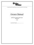
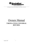
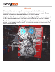
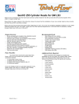
1
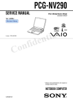
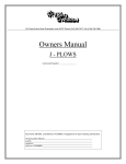
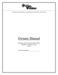
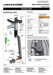
212 North Evans Road Evansdale, Iowa 50707 Phone (319)236-7977; Fax (319)236-7980
Owners Manual
AHW-025 MID MOUNT HYDRAULIC WING
Record the MODEL and SERIAL NUMBER of equipment for parts ordering information.
PURCHASED FROM:
DATE:
MODEL:
SERIAL NUMBER:
212 North Evans Road Evansdale, Iowa 50707 Phone (319)236-7977; Fax (319)236-7980
THIS PAGE LEFT BLANK
2
09700009
FORM 1-1.121.152-1
Revision 01
212 North Evans Road Evansdale, Iowa 50707 Phone (319)236-7977; Fax (319)236-7980
WARRANTY POLICY
Viking Cives, USA warrants products of its manufacture against defects in workmanship and material for a period of one year, from the
date of shipment to the customer. In consequence of this warranty, any component part or parts of such products proving defective within the above
specified time will be repaired or replaced F.O.B. factory. Providing such parts are returned, transportation prepaid, to the factory and found
defective by Viking Cives, USA.
This warranty will not apply to any product which has been repaired or altered outside of Viking Cives, USA factory in any way, so as in
Viking Cives, USA’s judgment, to affect its stability or reliability, nor which has been subject to misuse or accident.
The obligations of Viking Cives, USA under this warranty are limited to the replacement of defective parts. Such obligations are
exclusive and in lieu of all other remedies, warranties, guarantees of liabilities, expressed or implied, with respect to each product delivered,
hereunder, arising by law or otherwise (including without limitation any obligation or liability by Viking Cives, USA arising from negligence or
with respect to fitness, merchantability, loss of use, revenue, or profit, or consequential damages or injuries).
This limited warranty shall not be extended, altered, or varied except by a written instrument signed by Viking Cives, USA.
Viking Cives, USA assumes no responsibility for engines, electrical equipment or any other equipment and accessories not manufactured
by Viking Cives, USA beyond the warranty of the manufacturer of such equipment of accessories.
All warranty work done on Viking Cives, USA equipment must have prior authorization from Viking Cives, USA along with a
“Return Goods Authorization” number. All labor and parts issued by user for Viking Cives, USA warranty without an authorization number
and a signed authorization warranty form will be at the users own cost.
ORDERING PARTS
Delays and errors can be eliminated when ordering instructions are followed correctly.
1.
Place orders direct with Viking-Cives Group/nearest dealer.
2.
State Company name, address, and postal/zip code.
3.
Give the exact model and serial number of the equipment/unit (stamped on the unit identification plate.)
4.
Furnish part number, description and quantities required. Note: An alpha designation in the Item ID column indicates a sub-component
for that parent item. When placing parts orders reference the parent item to receive a complete assembly. Individual items can be
ordered separately if required by ordering the alpha designated item number.
5.
Print or type order clearly.
6.
Give specific shipping instructions.
VIKING-CIVES (USA) – RR2, Box 36-1/2; Harrisville, New York 13648; (315) 543-2321, (315) 543-2366 Fax
VIKING-CIVES (USA) Midwest Division – 212 North Evans Road; Evansdale, Iowa 50707; (319) 236-7977, (319) 236-7980 Fax
VIKING-CIVES LTD. – RR4, Box 1120; Mount Forest, Ontario, Canada N0G 2L0; (519) 323-4433, (519) 323-4608 Fax
3
09700009
FORM 1-1.121.152-1
Revision 01
212 North Evans Road Evansdale, Iowa 50707 Phone (319)236-7977; Fax (319)236-7980
WARRANTY REQUEST PROCEDURE
All repairs considered for warranty that are performed outside of Viking Cives, USA; require prior written authorization from Viking
Cives, USA. Failure to obtain written warranty authorization prior to repairs may result in the rejection of the warranty claim. To obtain
warranty consideration one must provide all required Viking Cives, USA with unit information including date of manufacture and serial
numbers. In most cases this information is easily obtained from the “Shipped Unit Tag” (located in most cases inside the driver’s side door)
and/or individual unit serial tag.
(A) To obtain Parts Warranty Consideration:
(1) Contact Viking Cives, USA customer service to obtain a Return Goods Authorization (RGA) number. Any product
arriving at Viking Cives, USA without a RGA number will be rejected and returned to the sender at his or her own
expense.
(2) Goods are to be shipped prepaid to Viking Cives, USA Evansdale, Iowa. All items should be clearly marked with the
appropriate RGA number.
(3) When a replacement item is shipped to replace a defective part for warranty consideration the following additional steps
will occur:
a) An invoice will be generated for the value of the replacement item(s).
b) The defective part(s) must be returned (prepaid) to Viking Cives, USA.
c) Upon receiving the defective part(s) Viking Cives, USA will issue and process a Discrepant Material Report
(DMR). Once the evaluation of the DMR report is complete and the parts are deemed warranty, a credit will
be issued against the outstanding invoice. If the part(s) are deemed Non-warranty the invoice will
remain outstanding to be paid to Viking Cives, USA. Any part(s) to be returned to the customer will be at
his or her own expense.
(B) To obtain Labor Parts Repair Warranty Consideration:
In the event that repairs are required outside of Viking Cives, USA facility that may be considered for warranty the following steps
must occur. Notification of Viking Cives, USA customer service must take place prior to the start of any repairs.
(1) Contact Viking Cives, USA customer service to obtain a Warranty Claim Form (WCF) and warranty authorization
number.
(2) Fill out all required WCF information and fax or mail the completed form to Viking Cives, USA, attention Customer
Service Department.
(3) Once the WCF report has been reviewed warranty authorization will be granted or denied. NOTE: Viking Cives, USA
warranty labor rates will apply unless specifically determined otherwise. Any part(s) involved in a WCF request
must follow the Parts Warranty Consideration procedures.
For Customer Service and/or Parts requests please contact:
([email protected]) are ([email protected])
Ph. (319) 236-7977; Fax (319) 236-7980
4
09700009
FORM 1-1.121.152-1
Revision 01
212 North Evans Road Evansdale, Iowa 50707 Phone (319)236-7977; Fax (319)236-7980
TABLE OF CONTENTS
DESCRIPTION/SECTION
PAGE NO
WARRANTY/ORDERING INFORMATION
WARRANTY REQUEST PROCEDURE
INTRODUCTION
REGISTRATION/ WARRANTY INFORMATION
SAFETY PRECAUTIONS/MESSAGES
INSTALLATION SEQUENCE & GUIDE LINES
3
4
6
8
8
10
PARTS
WING INSTALLATION
WING MOLDBOARD ASSEMBLY
WING POST ASSEMBLY
PUSH ARM ASSEMBLY
12
14
16
18
5
09700009
FORM 1-1.121.152-1
Revision 01
212 North Evans Road Evansdale, Iowa 50707 Phone (319)236-7977; Fax (319)236-7980
INTRODUCTION
This instruction/parts manual has operation and maintenance information for the Viking-Cives AHW-025 Mid Mount
Hydraulic Wing. It has been prepared to familiarize you with the design features of the unit, and to instruct you in its proper
operation and maintenance.
Read this manual carefully before you operate and/or service your AHW-025 Mid Mount Hydraulic Wing. Remember
that you’re working with heavy equipment that can injure you or someone else. You can help lessen the chance of injury by
following the procedures in this manual, carefully.
DANGER: If incorrectly used, this equipment can cause severe injury. Your chance of injury can be greatly reduced
by following all caution/warning decal notifications. All decals must be kept clean and complete. Replace any decals that are
unreadable. Decals may be purchased directly from Viking-Cives Group and/or the nearest authorized dealer. All Operator/Service
people should review this manual carefully and become familiar with its contents. If anyone else beside you operates or services
this equipment, make sure they read this manual and are instructed to follow the safety procedures related to this
equipment.
PERIODIC MAINTENANCE INSPECTION
DAILY INSPECTION AND LUBRICATION
Daily inspection along with periodic preventive maintenance will reduce the chance of any major repairs and down time
during equipment use.
1.
2.
3.
4.
5.
6.
7.
8.
Check the fluid level in the hydraulic oil reservoir. If the sight indicates low oil level, add the appropriate amount of the
specified hydraulic fluid. Cold Weather Operation: All equipment is designed to operate with hydraulic oil minimally
warm. During cold weather conditions, it is recommended that the truck be run at idle with the pump engaged and
circulating the oil through the system before operating equipment.
Grease all required components:
- All plow harness sheave nipples.
- All pump drive shaft nipples.
- Front and Rear tower sheave swivel blocks.
- Wing extension arm nipples.
- Front and Rear tower guide tracks.
- All front harness pivot points.
Check all components for loose and/or missing fasteners, if required tighten and/or replace.
Visually inspect all battery terminals and electrical connections, wires, switches, etc. for signs of corrosion, wear, loose
and/or broken connections, etc. At the beginning of each shift review all lighting accessories to ensure proper working
conditions, immediately replace any broken or non-functioning bulbs and/or lenses.
Visually inspect all hydraulic connections and hoses for cracks and/or leaks.
Check all cables, chains and sheaves for excessive wear or damage.
Visually inspect plow and wing units. Check cutting edges and wear shoes. If cutting edge has excessive wear remove and
rotate or if required replace. CAUTION: Do not allow cutting edge to wear down to mounting angle. Any wear to the
mounting angle may affect the operation and safety of the equipment. Replacement is costly.
At the beginning of each shift visually inspect all caution and warning decals. All decals should be complete and legible.
If decals are not legible, clean them. If cleaning the decals does not make them legible, install new decals.
6
09700009
FORM 1-1.121.152-1
Revision 01
212 North Evans Road Evansdale, Iowa 50707 Phone (319)236-7977; Fax (319)236-7980
GENERAL OPERATING INSTRUCTIONS
1.
2.
3.
4.
5.
The operator should familiarize himself with all equipment prior to operation. The in cabs controls are placed at a
comfortable reach of the operator, with an allowable amount of adjustment. If necessary, the controls can be adjusted for
either driver or passenger use.
The in cab control levers are arranged from left to right as the operator sees the plows.
- First lever:
Front Plow (One-way, Reversible, etc.)
- Second lever: Front of Wing
- Third lever:
Rear of Wing
- Fourth lever: Wing Brace (Slider)
All levers are clearly marked as to the equipment/function they control.
To raise the plow or wing, pull back on the appropriate control level, to lower the plow or wing, push the control level
forward. NOTE: The in cab controls are proportional to the hydraulic valve, therefore the further the control lever is
moved the faster the plow or wing will raise or lower.
Before putting any equipment into use, check for any worn, damaged or loose components, if necessary repair or replace.
Listen for any unusual sounds, if necessary repair and/or replace worn or damaged parts.
Before operating any equipment be sure to read and fully understand all caution and safety warnings. Familiarize yourself
and others with all caution/warning labels and their locations. Make sure all labels are complete and legible. Replace any
labels that have become unreadable and/or missing. Replacement labels can be purchased directly from Viking-Cives
Group and/or the nearest authorized dealer.
7
09700009
FORM 1-1.121.152-1
Revision 01
212 North Evans Road Evansdale, Iowa 50707 Phone (319)236-7977; Fax (319)236-7980
REGISTRATION OF EQUIPMENT AND WARRANTY INFORMATION
Report any damage to equipment at once to Viking Cives, USA. You should also register your equipment with Viking
Cives, USA, by filing out a warranty certificate and registration card and returning them to Viking Cives, USA. The warranty
period becomes effective upon date of delivery of equipment unless other arrangements have been made with a Viking Cives, USA.
Distributor or Viking Cives, USA. The information required to register the equipment may be found on the serial number tag
secured to the equipment.
A WORD ABOUT SAFETY:
The equipment described in this manual is normally being operated in winter conditions with bad weather and snow & ice conditions.
Due to these adverse operating conditions it is important that you the operator use good safety practices at all time to protect yourself
and co-workers and others when using the equipment.
It is not practical or possible to warn you about all the hazards associated with the operation and maintenance of this equipment. You
use your own good judgment supplemented with the information found on the safety decals, instructions in this manual, your
employer’s safety programs, safety codes, local, state/provincial, and federal laws, rules and regulations.
When operating/performing maintenance on this equipment, trouble shooting equipment operations and loading or unloading the
sanders/spreaders with material observe & obey all safety decals on the equipment and warnings listed in the manual. Failure to do
this could result in serious injury or death to you or others.
Remember at all times that as the operator you are responsible for the safe operation of this equipment and responsible for the safety
of others. Good safety practices not only protect you but also protect the people around you.
8
09700009
FORM 1-1.121.152-1
Revision 01
212 North Evans Road Evansdale, Iowa 50707 Phone (319)236-7977; Fax (319)236-7980
SPECIFICATIONS FOR RECOMMENDED PUMP AND PTO OPTIONS
PTO INFORMATION:
Crank Driven
Parker Chelsea
Model - 2230UA2XK
Model - 2442UW2XK
Transmission Mounted
Parker Chelsea
Model - 277XDFJPB5RB
The Chelsea 2330U series allows the driver to shift "on the go". The
2330 series runs at 88% of engine speed.
The economical 2440 series is a manual shift PTO that requires the
operator to stop the engine before shifting. The 2442UW2XK runs at
89% of engine speed.
The Chelsea 277 series power shift exceeds the torque capacity of a 6bolt PTO, while offering the tighter sealing of a 10-bolt pattern. The
277 series runs at 87% of engine speed.
PUMP INFORMATION:
SINGLE PUMPS:
Permco
Model - P2100A231ADXE17-14
Pump flow 16 GPM @ 1200 RPM
Maximum operating pressure 2250 PSI
Model - 2PL220ASDV-ULT
Pump flow 18 GPM @ 1000 RPM; 32 GPM @ 1800 RPM
Maximum operating pressure
Model - DVP16180A
Pump flow 20 GPM @ 1500 RPM
Maximum operating pressure 2250 PSI
Dowty Dry Valve
Tyrone Dry Valve
TANDEM PUMPS:
Permco
Model - P3000B231AXZK17-14AZK17-1
Dowty Dry Valve
Pump flow 16 GPM @ 1200 RPM (Both Sides)
Maximum operating pressure 2250 PSI
Model - 2PL1582PL220DVTP
Pump flow 13 GPM @ 1000 RPM; 23 GPM @ 1800 RPM (1st stage)
18 GPM @ 1000 RPM; 32 GPM @ 1800 RPM (2nd stage)
Maximum operating pressure 2250 PSI
Model - DVTP16150180A
Pump flow 20 GPM @ 1500 RPM (1st stage)
16 GPM @ 1500 RPM (2nd stage)
Maximum operating pressure 2250 PSI
Tyrone Dry Valve
9
09700009
FORM 1-1.121.152-1
Revision 01
212 North Evans Road Evansdale, Iowa 50707 Phone (319)236-7977; Fax (319)236-7980
INSTALLATION SEQUENCE AND GUIDE LINES
These mounting instructions are intended as a guide to aid you in the installation of your AHW-025 Mid Mount Hydraulic
Wing. All dimensions noted in the instructions are approximate and may vary due to make and model of chassis, tire size. Type of
suspension, spring deflection, customer preference and interference caused by immovable objects such as a transfer case. VikingCives assumes no responsibility for improper installation unless installed at an approved Viking-Cives location. The end-user and the
installer prior to installation should discuss mounting location in order to achieve the best possible installation.
1.
2.
Layout chassis frame rails, following layout drawings supplied, identifying any chassis components such as air tanks or battery
boxes, which may have to be moved.
Layout side mounting plates and support masts as indicated (for dimensions see table below).
- Drill and bolt side plates to chassis frame as necessary. When mounting side plates use existing frame holes when
possible.
- Punch holes (11/16” diameter) in right side plates only, for angles that fasten post and support tube to plates.
- Weld 1/2” x 1 1/4” reinforcement bars on all side plates.
- Weld support angle 3” x 3” x 3/8” x 11”, behind front/rear side plates where they meet the frame.
MID MOUNT WING INSTALLATION – W/ STANDARD WING
A
B
C
D
E
F
3.
6 FT/7 FT
13”
40”
12 1/2”
26”
24 1/4”
40 1/8”
8 FT/9 FT
13”
50”
12 1/2”
26”
24 1/4”
50 1/8”
10 FT/11 FT
13”
55”
12 1/2”
26”
24 1/4”
55 1/8”
Install front mast and rear support tube.
- Slide front mast assembly and rear support tube into side plate cutouts.
- Locate front mast 24 1/4” (measurement E) from face of front right side mounting plate to outer edge of vertical support
channel.
- Locate rear support tube 26” (measurement D) from face rear right side mounting plate to outside edge of tube end plate.
- Install eight 4” x 3” x 1/2” x 6” angles to secure mast assembly and support tube in place. Bolt right side angles to side
mounting plates with 5/8” x 2” bolts, nuts and lock washers and weld to the top and bottom of the tube. Weld the left
side angles to the side mounting plates and bolt through the tubes with 5/8” x 6 bolts, nuts, and lock washers. By
following this installation sequence the front mast assembly and rear support tube will remain removable and easily reinstalled.
4. Layout and install pipe brace between front mast and rear support tube.
- Weld mounting angles to right hand inside of front mast and rear support tubes (locate as shown).
- Attach cast-mounting balls to mounting angles with fasteners. Measure and cut pipe brace to suit, weld pipe to castmounting balls.
5. Install moldboard assembly onto front wing post mounting block using 1 1/4” x 6 1/2” bolt supplied.
6. Next layout and install rear push arm.
- Attach push arm to the rear support tube on right hand side.
- Next install the rear push arm-mounting bracket to the moldboard. Layout the mounting bracket onto the moldboard so
that you obtain a 90-degree angle with the push arm and the rear cross beam. Location may vary based on moldboard
length and distance between front mast and rear support tube.
- Attach push arm to the moldboard.
7. Hydraulics Installation – Various hydraulic arrangements/options are available and care must be taken to use the correct
drawings for your specific application. When running control cables and/or hydraulic hoses, care must be taken not to run these
items to close to moving parts and/or hot engine parts. Do not kink or severely bend cable or hoses, at any point were items cross
10
09700009
Revision 01
FORM 1-1.121.152-1
212 North Evans Road Evansdale, Iowa 50707 Phone (319)236-7977; Fax (319)236-7980
8.
any surfaces were abrasion could occur, protect cable or hose with armor. Whenever possible, secure the cables and/or hoses,
with ties, to the chassis frame. Cold Weather Operation: All equipment is designed to operate with hydraulic oil minimally
warm. During cold weather conditions, it is recommended that the truck be run at idle with the pump engaged and circulating the
oil through the system before operating equipment.
- Install chassis mounted hydraulic components (i.e. hydraulic pump/PTO, main valve bank, etc).
- Install heel lift cylinder from front post block to cylinder link in center of moldboard using pins provided.
- Install hydraulic plumbing for front and heel lift cylinders.
Final installation and inspection.
- Operate wing and build wing stop on rear tube so wing will not hit body in up position.
- Install safety chain around push arm for securing wing in raised travel position.
- Check all components for loose and/or missing fasteners, if required tighten and/or replace.
- Visually inspect all hydraulic connections and hoses for leaks.
- Visually inspect all caution and warning decals, replace decals if missing. All decals should be complete and legible.
11
09700009
FORM 1-1.121.152-1
Revision 01
212 North Evans Road Evansdale, Iowa 50707 Phone (319)236-7977; Fax (319)236-7980
AHW-025 MID MOUNT WING KIT COMPLETE
For ordering complete kits please reference table below. These kits come complete with all standard items and necessary
installation hardware.
ITEM ID
ITEM NO
01401158
01401068
01401168
01401165
DESCRIPTION
MID MOUNT WING KIT AHW-025 6FT 12IN
MID MOUNT WING KIT AHW-025 7FT 12IN
MID MOUNT WING KIT AHW-025 8FT 12IN
MID MOUNT WING KIT AHW-025 9FT 12IN
QTY REQ
1
1
1
1
AHW-025 MID MOUNT WING KIT INSTALLATION
ITEM ID
1
2
3
4
5
6
7
8
9
10
11
12
13
14
15
16
17
18
ITEM NO
00401494
00401495
00402187
01001167
01001170
01001176
01001177
01001178
01201065
A/R
01900155
0540246
HW14C-10
HW30A-10
HW36D-16
HW40A-1016
HW40A-1048
HW40A-1628
DESCRIPTION
ANGLE 3 X 3 X 3/8 - 11
ANGLE 4 X 3 X 1/2 - 6
ANGLE 4 X 4 X 3/8 - 4
HINGE BLOCK WELD'T AHW-025
FRAME MTG PLATE 12" X 28"
WING POST ASS'Y AHW-025
FRAME MTG PLATE 18" X 28"
REAR CROSS TUBE WELD'T
PUSH ARM ASS'Y AHW-025
MOLDBOARD ASS'Y AHW-025
PIPE BRACE KIT 2 7/8 BALL - 48.000 IN LG
CYLINDER HYD DA 3 X 10
LOCKWASHER SPLIT 5/8 ZINC
NUT HEX 5/8 UNC ZINC
NUT HEX ELASTIC 1 UNC ZINC
BOLT HEX 5/8 X 2 UNC ZINC
BOLT HEX 5/8 X 6 UNC ZINC
BOLT HEX 1 X 3 1/2 UNC ZINC
QTY REQ
4
8
2
1
2
1
2
1
1
1
1
1
6
6
2
4
2
2
12
09700009
FORM 1-1.121.152-1
Revision 01
212 North Evans Road Evansdale, Iowa 50707 Phone (319)236-7977; Fax (319)236-7980
MOLDBOARD ASS’Y AHW-025
ITEM ID
1
2
3
4
5
6
7
8
9
10
11
12
ITEM NO
01401157
01401065
01401167
01401164
01401132
01401051
01401131
01401162
00401422
00900125
00900139
HW14B-20
HW13A-0848
HW30C-20
0500146
0500114
0500147
0500148
HW40C-1020
HW14C-10
HW30A-10
01401063
DESCRIPTION
MOLDBOARD ASS'Y AHW-025 6FT 12IN
MOLDBOARD ASS'Y AHW-025 7FT 12IN
MOLDBOARD ASS'Y AHW-025 8FT 12IN
MOLDBOARD ASS'Y AHW-025 9FT 12IN
MOLDBOARD WELD'T AHW-025 6FT 12IN
MOLDBOARD WELD'T AHW-025 7FT 12IN
MOLDBOARD WELD'T AHW-025 8FT 12IN
MOLDBOARD WELD'T AHW-025 9FT 12IN
LINK 1.063D 7.188 1.313D
PIN 1.250 DIA X 0.594 WELD'T
BOLT DRILLED 1.250 DIA X 3.250
FLATWASHER USS 1 1/4 ZINC
COTTER PIN 1/4 X 3 ZINC
NUT HEX SLOTTED 1 1/4 UNC ZINC
BLADE 12 TP 5/8 X 8 X 72
BLADE 12 TP 5/8 X 8 X 84
BLADE 12 TP 5/8 X 8 X 96
BLADE 12 TP 5/8 X 8 X 108
BOLT CARRIAGE 5/8 X 2 1/2 UNC ZINC
LOCKWASHER SPLIT 5/8 ZINC
NUT HEX 5/8 UNC ZINC
PUSH ARM MTG BRK'T WELD'T
QTY REQ
1
1
1
1
1
1
1
1
2
1
1
1
1
1
A/R
A/R
A/R
1
14
09700009
FORM 1-1.121.152-1
Revision 01
212 North Evans Road Evansdale, Iowa 50707 Phone (319)236-7977; Fax (319)236-7980
01001176: WING POST ASS'Y AHW-025
ITEM ID
1
2
3
4
5
6
7
8
9
10
11
12
ITEM NO
01001172
01001168
00900127
00900130
0540247
HW40A-2056
HW14B-20
HW36D-20
HW13B-0432
HW29E-04
HW40A-0416
HW36D-04
DESCRIPTION
WING POST WELD'T AHW-025
SLIDE WELD'T AHW-025
PIN 1.500 DIA X 11.438 WELD'T
PIN 1.000 DIA X 6.500
CYLINDER HYD DA 4 X 12
BOLT HEX 1 1/4 X 7 UNC ZINC
FLATWASHER USS 1 1/4 ZINC
NUT HEX ELASTIC 1 1/4 UNC ZINC
ROLL PIN 1/8 X 2 ZINC
GREASE FITTING 1/4 28 STR
BOLT HEX 1/4 X 2 UNC ZINC
NUT HEX ELASTIC 1/4 UNC ZINC
QTY REQ
1
1
1
1
1
1
1
1
2
4
1
1
16
09700009
FORM 1-1.121.152-1
Revision 01
212 North Evans Road Evansdale, Iowa 50707 Phone (319)236-7977; Fax (319)236-7980
01201065: PUSH ARM ASS'Y AHW-025 (40 INCH)
ITEM ID
1
2
3
4
5
6
7
8
9
10
ITEM NO
01201064
01201060
01201062
0580024
00900129
HW13A-0848
HW40A-1232
HW36D-12
HW40A-0832
HW36D-08
DESCRIPTION
PUSH ARM WELD'T AHW-025 OUTER (40 INCH)
PUSH ARM WELD'T AHW-025 INNER
SWIVEL CONNECTOR WELD'T
SPRING COMP 3.531 X 0.563 X 6.641
PIN 1.250 DIA X 4.500 BODY
COTTER PIN 1/4 X 3 ZINC
BOLT HEX 3/4 X 4 UNC ZINC
NUT HEX ELASTIC 3/4 UNC ZINC
BOLT HEX 1/2 X 4 UNC ZINC
NUT HEX ELASTIC 1/2 UNC ZINC
QTY REQ
1
1
2
1
2
2
2
2
1
1
01201096: PUSH ARM ASS'Y AHW-025 (66 INCH)
ITEM ID
1
2
3
4
5
6
7
8
9
10
ITEM NO
01201095
01201060
01201062
0580024
00900129
HW13A-0848
HW40A-1232
HW36D-12
HW40A-0832
HW36D-08
DESCRIPTION
PUSH ARM WELD'T AHW-025 OUTER (66 INCH)
PUSH ARM WELD'T AHW-025 INNER
SWIVEL CONNECTOR WELD'T
SPRING COMP 3.531 X 0.563 X 6.641
PIN 1.250 DIA X 4.500 BODY
COTTER PIN 1/4 X 3 ZINC
BOLT HEX 3/4 X 4 UNC ZINC
NUT HEX ELASTIC 3/4 UNC ZINC
BOLT HEX 1/2 X 4 UNC ZINC
NUT HEX ELASTIC 1/2 UNC ZINC
QTY REQ
1
1
2
1
2
2
2
2
1
1
18
09700009
FORM 1-1.121.152-1
Revision 01
212 North Evans Road Evansdale, Iowa 50707 Phone (319)236-7977; Fax (319)236-7980
Notes:
20
09700009
FORM 1-1.121.152-1
Revision 01