1
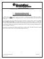
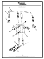
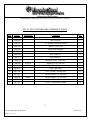
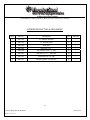
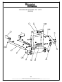
Medium Duty Gen II
Parts & Service Manual
Unit Serial Number: ________________
Record the MODEL and SERIAL NUMBER of equipment for parts ordering information.
PURCHASED FROM:
DATE:
MODEL:
SERIAL NUMBER:
22956 Highway 61 Morley, MO 63767 Phone (573) 262-3545 Fax (573) 262-3540
TABLE OF CONTENTS
DESCRIPTION
PAGE NO.
Warranty Policy
Ordering Parts
Warranty Request Procedure
Introduction / Periodic maintenance Inspection / Daily Inspection & Lubrication
Registration of Equipment & warranty Information / A Word About Safety
Moldboard / Push Frame Assembly Instructions
Cushion Valves with Central Hydraulic Systems
Drawing of Cushion Valve
Parts Break Down of Cushion Valve
Maintenance Procedure (Tightening Packing Nuts on Snowplow Cylinders)
Torque Arm Removal
Drawing of Medium Duty Assembly
Parts Break Down of Medium Duty Assembly
Drawing of 10’ Poly Moldboard Assembly
Parts break down of 10’ Poly Moldboard Assembly
Drawing of 10’ Steel Moldboard Assembly
Parts Break Down of 10’ Steel Moldboard Assembly
Drawing of 36R 10’ Poly Moldboard Assembly
Parts Break Down of 36R 10’ Poly Moldboard Assembly
Drawing of Blade / Hinge Assembly
Parts Break Down of Blade / Hinge Assembly
Drawing of Rubber Deflector & Skid Shoes
Parts Break Down of Rubber Deflector & Skid Shoes
Drawing of MD Push Frame Assembly
Parts Break Down of MD Push Frame Assembly
Drawing of Universal Tilt Hitch
Parts Break Down of Universal Tilt Hitch
General Operating Instructions
Electrical
Warranty
3
3
4
5
6
7
8
10
11
12
13
14
15
16
17
18
19
20
21
22
23
24
25
26
27
28
29
30
31-35
37
2
New Sno-King MD Gen II 060807
FORM 1-1.121.152-1
Revision 07
22956 Highway 61 Morley, MO 63767 Phone (573) 262-3545 Fax (573) 262-3540
WARRANTY POLICY
Wheeler Steel and Truck Equipment, Inc. warrants products of it’s manufacture against defects in workmanship and material
for a period of one year, from the date of shipment to the customer. In consequence of this warranty, any component part or parts of
such products proving defective within the above specified time will be repaired or replaced F.O.B. factory. Providing such parts are
returned, transportation prepaid, to the factory and found defective by Wheeler Steel and Truck Equipment, Inc.
This warranty will not apply to any product which has been repaired or altered outside of Wheeler Steel and Truck
Equipment, Inc. factory in any way, so as in Wheeler Steel and Truck Equipment, Inc.’s judgement, to affect its stability or
reliability, nor which has been subject to misuse or accident.
The obligations of Wheeler Steel and Truck Equipment, Inc. under this warranty are limited to the replacement of defective
parts. Such obligations are exclusive and in lieu of all other remedies, warranties, guarantees of liabilities, expressed or implied,
with respect to each product delivered, hereunder, arising by law or otherwise (including without limitation any obligation or
liability by Wheeler Steel and Truck Equipment, Inc. arising from negligence or with respect to fitness, merchantability, loss of use,
revenue, or profit, or consequential damages or injuries).
This limited warranty shall not be extended, altered, or varied except by a written instrument signed by Wheeler Steel and
Truck Equipment, Inc.
Wheeler Steel and Truck Equipment, Inc. assumes no responsibility for engines, electrical equipment or any other
equipment and accessories not manufactured by Wheeler Steel and Truck Equipment, Inc. beyond the warranty of the manufacturer
of such equipment of accessories.
All warranty work done on Wheeler Steel and Truck Equipment, Inc. equipment must have prior authorization from
Wheeler Steel and Truck Equipment, Inc., along with a “Return Goods Authorization” number. All labor and parts issued by user
for Wheeler Steel & Truck Equipment, Inc warranty without an authorization number and a signed authorization warranty form will
be at the users own cost.
ORDERING PARTS
Delays and errors can be eliminated when ordering instructions are followed correctly.
1.
Place orders direct with Wheeler Steel and Truck Equipment, Inc. / nearest dealer.
2.
State Company name, address, and postal/zip code.
3.
Give the exact model and serial number of the equipment/unit (stamped on the unit identification plate.)
4.
Furnish part number, description and quantities required. Note: An alpha designation in the Item ID column indicates a
sub-component for that parent item. When placing parts orders reference the parent item to receive a complete assembly.
Individual items can be ordered separately if required by ordering the alpha designated item number.
5.
Print or type order clearly.
6.
Give specific shipping instructions.
WHEELER STEEL & TRUCK EQUIPMENT, INC – 22956 Hwy 61 Morley, MO 63767; (573) 262-3545, (573) 262-3369 Fax
3
New Sno-King MD Gen II 060807
FORM 1-1.121.152-1
Revision 07
22956 Highway 61 Morley, MO 63767 Phone (573) 262-3545 Fax (573) 262-3540
WARRANTY REQUEST PROCEDURE
All repairs considered for warranty that is performed outside of Wheeler Steel and Truck Equipment, Inc., require prior
written authorization from Wheeler Steel and Truck Equipment, Inc. Failure to obtain written warranty authorization prior to
repairs may result in the rejection of the warranty claim. To obtain warranty consideration one must provide all required
Wheeler Steel and Truck Equipment, Inc. with unit information including date of manufacture and serial numbers. In most
cases this information is easily obtained from the “Shipped Unit Tag” and/or individual unit serial tag.
(A) To obtain Parts Warranty Consideration:
(1) Contact Wheeler Steel and Truck Equipment, Inc. A customer service to obtain a Return Goods
Authorization (RGA) number. Any product arriving at Wheeler Steel and Truck Equipment, Inc. without a
RGA number will be rejected and returned to the sender at his or her own expense.
(2) Goods are to be shipped prepaid to Wheeler Steel and Truck Equipment, Inc. 22956 Highway 61 Morley, MO
63767. All items should be clearly marked with the appropriate RGA number.
(3) When a replacement item is shipped to replace a defective part for warranty consideration the following
additional steps will occur:
a) An invoice will be generated for the value of the replacement item(s).
b) The defective part(s) must be returned (prepaid) to Wheeler Steel and Truck Equipment, Inc.
c) Upon receiving the defective part(s) Wheeler Steel and Truck Equipment, Inc. will issue and
process a Discrepant Material Report (DMR). Once the evaluation of the DMR report is complete
and the parts are deemed warranty, a credit will be issued against the outstanding invoice. If the
part(s) are deemed Non-warranty the invoice will remain outstanding to be paid to Wheeler
Steel and Truck Equipment, Inc. Any part(s) to be returned to the customer will be at his or her
own expense.
(B) To obtain Labor Parts Repair Warranty Consideration:
In the event that repairs are required outside of Wheeler Steel and Truck Equipment, Inc. facility that may be
considered for warranty the following steps must occur. Notification of Wheeler Steel and Truck Equipment, Inc.
customer service must take place prior to the start of any repairs.
(1) Contact Wheeler Steel and Truck Equipment, Inc. customer service to obtain a Warranty Claim Form (WCF)
and warranty authorization number.
(2) Fill out all required WCF information and fax or mail the completed form to Wheeler Steel and Truck
Equipment, Inc., attention Customer Service Department.
(3) Once the WCF report has been reviewed warranty authorization will be granted or denied. NOTE: Wheeler
Steel and Truck Equipment, Inc. warranty labor rates will apply unless specifically determined
otherwise. Any part(s) involved in a WCF request must follow the Parts Warranty Consideration procedures.
For Customer Service and/or Parts requests please contact:
Service Department – Daniel Wheeler
Ph. (573) 262-3545; Fax (573) 262-3369
4
New Sno-King MD Gen II 060807
FORM 1-1.121.152-1
Revision 07
22956 Highway 61 Morley, MO 63767 Phone (573) 262-3545 Fax (573) 262-3540
INTRODUCTION
This instruction/parts manual has operation and maintenance information for the Viking-Cives / Sno-King Equipment. It
has been prepared to familiarize you with the design features of the unit, and to instruct you in its proper operation and maintenance.
Read this manual carefully before you operate and/or service your Sno-King Equipment. Remember that you’re working
with heavy equipment that can injure you or someone else. You can help lessen the chance of injury by following the procedures in
this manual, carefully.
DANGER: If incorrectly used, this equipment can cause severe injury. Your chance of injury can be greatly reduced
by following all caution/warning decal notifications. All decals must be kept clean and complete. Replace any decals that are
unreadable. Decals may be purchased directly from Viking-Cives Group and/or the nearest authorized dealer. All Operator/Service
people should review this manual carefully and become familiar with its contents. If anyone else beside you operates or services
this equipment, make sure they read this manual and are instructed to follow the safety procedures related to this
equipment.
PERIODIC MAINTENANCE INSPECTION
DAILY INSPECTION AND LUBRICATION
Daily inspection along with periodic preventive maintenance will reduce the chance of any major repairs and down time
during equipment use.
1.
2.
3.
4.
5.
6.
7.
Check the fluid level in the hydraulic oil reservoir. If the sight indicates low oil level, add the appropriate amount of the
specified hydraulic fluid. Cold Weather Operation: All equipment is designed to operate with hydraulic oil minimally
warm. During cold weather conditions, it is recommended that the truck be run at idle with the pump engaged and
circulating the oil through the system before operating equipment.
Grease all required components:
- All pump drive shaft nipples.
- All front harness pivot points.
Check all components for loose and/or missing fasteners, if required tighten and/or replace.
Visually inspect all battery terminals and electrical connections, wires, switches, etc. for signs of corrosion, wear, loose
and/or broken connections, etc. At the beginning of each shift review all lighting accessories to ensure proper working
conditions, immediately replace any broken or non-functioning bulbs and/or lenses.
Visually inspect all hydraulic connections and hoses for cracks and/or leaks.
Visually inspect plow units. Check cutting edges and wear shoes. If cutting edge has excessive wear remove and rotate or
if required replace. CAUTION: Do not allow cutting edge to wear down to urethane hinge. Any wear to the mounting
angle may affect the operation and safety of the equipment. Replacement is costly.
At the beginning of each shift visually inspect all caution and warning decals. All decals should be complete and legible.
If decals are not legible, clean them. If cleaning the decals does not make them legible, install new decals.
5
New Sno-King MD Gen II 060807
FORM 1-1.121.152-1
Revision 07
22956 Highway 61 Morley, MO 63767 Phone (573) 262-3545 Fax (573) 262-3540
REGISTRATION OF EQUIPMENT AND WARRANTY INFORMATION
Report any damage to equipment at once to Viking Cives, USA. You should also register your equipment with
Wheeler Steel & Truck Equipment, Inc, by filing out a warranty certificate and registration card and returning them to
Viking Cives, USA. The warranty period becomes effective upon date of delivery of equipment unless other
arrangements have been made with a Wheeler Steel & Truck Equipment, Inc Distributor or Wheeler Steel & Truck
Equipment, Inc. The information required to register the equipment may be found on the serial number tag secured to
the equipment.
Patent # 6,536,141
Model NO. 1034DT / SERIAL NO._______________
22956 Hwy 61 Morley, MO 63767
Phone (573) 262-3545 / Fax (572) 262-3369
A WORD ABOUT SAFETY:
The equipment described in this manual is normally being operated in adverse winter conditions with bad weather, snow
and ice. Due to these adverse operating conditions it is important that you the operator use good safety practices at all
time to protect yourself, co-workers and others when using the equipment.
It is not practical or possible to warn you about all the hazards associated with the operation and maintenance of this
equipment. You should always use your own good judgment supplemented with the information found on the safety
decals, instructions in this manual, your employer’s safety programs, safety codes, local, state/provincial, and federal
laws, rules and regulations.
When operating/performing maintenance on this equipment, trouble shooting equipment operations and loading or
unloading the sanders/spreaders with material observe & obey all safety decals on the equipment and warnings listed in
the manual. Failure to do this could result in serious injury or death to you or others.
Remember at all times that as the operator you are responsible for the safe operation of this equipment and responsible for
the safety of others. Good safety practices not only protect you but also protect the people around you.
6
New Sno-King MD Gen II 060807
FORM 1-1.121.152-1
Revision 07
22956 Highway 61 Morley, MO 63767 Phone (573) 262-3545 Fax (573) 262-3540
SNO-KING MOLDBOARD / PUSHFRAME
ASSEMBLY INSTRUCTIONS
1. Position the moldboard assembly face down on a flat surface.
2. Remove the factory installed 1” and ¾” fasteners from the left and right torque arm assemblies.
3. Utilizing adequate lifting equipment and proper safety procedures, position the torque tube and a-frame
assembly into the rear moldboard cavity and attach with the 1” X 2½” fine thread bolts and flat washers,
(a coating of premium grade anti-seize thread compound is recommended) but do not completely tighten
at this time.
4. Rotate the torque tube and a-frame assembly towards the moldboard and attach, but do not completely
tighten at this time, the torque arms to the center moldboard rib adjusting holes with the ¾” X 2½” bolts
and nuts while positioning the flat washers on the moldboard side of the ribs.
5. Apply thread sealant onto the 90-degree pipe fittings and install into the moldboard reversing cylinders.
6. Attach the correct reversing cylinder hose assemblies as indicated in the parts and service manual for
your hydraulic application. A cushion valve is required on all central hydraulic systems. (Please note
memo on the following page)
7. Connect each end of the lift chain assembly to the a-frame lifting lugs with the 3/8” clevis midlinks
provided.
8. Once the completed plow assembly has been properly installed on the truck it will be necessary to adjust
the moldboard to an angle of attack of 22-25 degrees and adequately tighten both the torque tube and
torque arm fasteners at that time.
7
New Sno-King MD Gen II 060807
FORM 1-1.121.152-1
Revision 07
22956 Highway 61 Morley, MO 63767 Phone (573) 262-3545 Fax (573) 262-3540
SNO-KING CUSHION VALVES
WITH CENTRAL HYDRAULIC SYSTEMS
A cushion valve is always required in the reverse circuit of a Sno-King snowplow! When you purchase a
package which includes an electric / hydraulic power unit, a relief valve is an integral part of the power unit
reverse valve.
When you purchase a Sno-King medium duty package less hydraulics (SK0110, SK0210, SK0310) no cushion
valve is included in the package – we consider them to be a part of the hydraulic package. A cushion valve
for reverse cylinder protection must be included in your hydraulic package or certain cylinder failure will result.
We recommend a cushion valve with a relief setting between 2,000 to 2,500 psi (maximum working pressure of
the reverse cylinder is 2,500 psi).
The majority of our Dealers have opted to supply their own cushion valves. Sno-King will make an optional
cushion valve available to those of you that wish to purchase them from us.
8
New Sno-King MD Gen II 060807
FORM 1-1.121.152-1
Revision 07
22956 Highway 61 Morley, MO 63767 Phone (573) 262-3545 Fax (573) 262-3540
NOTES:
______________________________________________________
_____________________________________________
_____________________________________________
_____________________________________________
_____________________________________________
_____________________________________________
_____________________________________________
_____________________________________________
_____________________________________________
_____________________________________________
_____________________________________________
_____________________________________________
_____________________________________________
_____________________________________________
_____________________________________________
_____________________________________________
_____________________________________________
_____________________________________________
9
New Sno-King MD Gen II 060807
FORM 1-1.121.152-1
Revision 07
22956 HWY 61 PO BOX 295 MORLEY, MO 63767 (573)262-3545 PH (573)262-3369 FX
CUSHION VALVE
2
8
4
6
7
4
1
1
6
1
3
3
5
5
10
EQUIPMENT MAY NOT BE EXACTLY AS SHOWN. SOME COMPONENTS MAY BE OPTIONAL
TO MAINTAIN OUR ON-GOING PRODUCT AND DEVELOPMENT IMPROVEMENT PROGRAM, VIKING-CIVES RESERVES THE RIGHT TO CHANGE EQUIPMENT & SPECIFICATION WITHOUT NOTICE.
This Owner's Manual File is Contained Within
CUSHION VALVE.idw
22956 Highway 61 Morley, MO 63767 Phone (573) 262-3545 Fax (573) 262-3540
CUSHION VAVLE
Item
Part No.
Description
Qty.
1
2180244
Cushion Valve
1
2
3SK4100
3/8” x 24” Hose Assembly
2
3
3SK4110
3/8” x 48” Hose Assembly
2
4
3SK4130
3/8” 90 Degree Swivel Adaptor
2
5
3SK4190
3/8” Quick Coupler
2
6
3SK3495
Bolt Hex 5/16” x 2 ½” unc zinc
2
7
3SK3496
Nut hex top lock 5/16” unc zinc
2
8
3SK4190
3/8 Quick disconnect
8
Optional
11
New Sno-King MD Gen II 060807
FORM 1-1.121.152-1
Revision 07
22956 Highway 61 Morley, MO 63767 Phone (573) 262-3545 Fax (573) 262-3540
MAINTENANCE PROCEDURE:
TIGHTENING PACKING NUTS ON SNOWPLOW CYLINDERS
Adjusting packing nuts are used on snowplow cylinders to hold the cylinder together as well as providing
pressure against the chevron style rod packing. The v-shaped packing flare out and seal tightly against the rod
surface as the nut is tightened.
Often times, it is necessary to adjust the packing nut in the field if oil starts to leak from the cylinder. This
occurs because the seals tend to wear in after 100 cycles and need to have more pressure applied to them.
The proper adjustment procedure for the packing nut is listed below:
1. Loosen the packing nut.
2. Tighten the packing nut by hand until it is snug against the packing.
3. Use a nut wrench to tighten the nut ¾ turn.
This simple procedure should produce a torque valve on the nut of 50 foot-pounds and should provide a dry rod
when cycled.
12
New Sno-King MD Gen II 060807
FORM 1-1.121.152-1
Revision 07
22956 Highway 61 Morley, MO 63767 Phone (573) 262-3545 Fax (573) 262-3540
TORQUE ARM REMOVAL
NEVER USE HEAT TO AID IN THE REMOVAL OF TORQUE
ARMS – THE URETHANE WILL MELT AND BE RUINED.
•
Proper torque arm removal is accomplished by installing a 1” NF size bolt into the threaded hole in the center of
the torque arm shaft. The bolt should have a loop welded to it to allow attachment of cable to “pull” the torque
arm from the torque tube. A straight – in line pull is required. To install the arms, adequately lubricate the inside
of the torque tube, the outside of the torque arms, and press the arms into the torque tube while protecting the
threads. Do not pound on the steel arm portion of the torque arm – this will bend the arm and damage the part.
•
Please contact the Service Department at (573) 262-3545 if you have any questions.
13
New Sno-King MD Gen II 060807
FORM 1-1.121.152-1
Revision 07
22956 HWY 61 PO BOX 295 MORLEY, MO 63767 (573)262-3545 PH (573)262-3369 FX
MEDIUM DUTY ASSEMBLY
5
4
3
2
6
1
14
EQUIPMENT MAY NOT BE EXACTLY AS SHOWN. SOME COMPONENTS MAY BE OPTIONAL
TO MAINTAIN OUR ON-GOING PRODUCT AND DEVELOPMENT IMPROVEMENT PROGRAM, VIKING-CIVES RESERVES THE RIGHT TO CHANGE EQUIPMENT & SPECIFICATION WITHOUT NOTICE.
This Owner's Manual File is Contained Within
MD PLOW ASSEMBLY.idw
22956 Highway 61 Morley, MO 63767 Phone (573) 262-3545 Fax (573) 262-3540
MEDIUM DUTY ASSEMBLY PARTS
Item
Part No.
Description
Qty.
1
3SK2171-3
MD Push Frame
1
2
3SK2131
MD Torque Tube weldment
1
3
3SK2125
10’ Moldboard Assembly
1
4
202600143
21” Swivel
1
5
3SK3492
60” Sno-King Chain
1
6
3SK3488
½” midlink
2
Optional
15
New Sno-King MD Gen II 060807
FORM 1-1.121.152-1
Revision 07
22956 HWY 61 PO BOX 295 MORLEY, MO 63767 (573)262-3545 PH (573)262-3369 FX
10' POLY MOLDBOARD ASSEMBLY
13
12
10
2
11
6
1
8
5
8
11
3
5
14
11
4
7
NOTES: ITEM 13 IS NOT SHOWN
ON THE DRAWING
16
EQUIPMENT MAY NOT BE EXACTLY AS SHOWN. SOME COMPONENTS MAY BE OPTIONAL
TO MAINTAIN OUR ON-GOING PRODUCT AND DEVELOPMENT IMPROVEMENT PROGRAM, VIKING-CIVES RESERVES THE RIGHT TO CHANGE EQUIPMENT & SPECIFICATION WITHOUT NOTICE.
This Owner's Manual File is Contained Within
10' MOLDBOARD.idw
22956 Highway 61 Morley, MO 63767 Phone (573) 262-3545 Fax (573) 262-3540
10’ POLY MOLDBOARD ASSEMBLY PARTS
Item
Part No.
1
Alt. Part No.
Description
Qty.
3SK2125
10’ Poly moldboard
1
2
3SK7076
10’ Poly sheet
1
3
3SK7071
120” Adiprene trip hinge
1
4
3SK7166
Plate washer 26”
3
5
3SK7167
Plate washer 6”
2
6
3SK3722
Bolt hex 5/8 x 3 ½ unc zinc
3
7
2N81074
5/8” x 3” plow bolt
12
8
3SK3720
5/8” x 3” grade 5 carriage bolt
10
9
3SK3698
81072
Bolt hex 5/8 x 1 ½ unc zinc
6
10
3SK3585
81091
Bolt hex 3/8 x 1 ½ unc zinc
24
11
3SK3781
Nut hex toplock 5/8” unc zinc
31
12
3SK3591
Nut hex toplock 3/8 unc zinc
24
13
3SK3595
Flatwasher sae 3/8 zinc
24
14
3SK3768
5/8” x 2 ½” O.D. washer
12
15
3SK7121
Blade 3/4 x 6 x 120
1
81086C
17
New Sno-King MD Gen II 060807
FORM 1-1.121.152-1
Revision 07
22956 HWY 61 PO BOX 295 MORLEY, MO 63767 (573)262-3545 PH (573)262-3369 FX
10' STEEL MOLDBOARD ASSEMBLY
1
12
9
7
12
10
3
4
4
13
12
11
6
5
2
NOTES: ITEM NUMBER 13 IS NOT
SHOWN ON DRAWING
18
EQUIPMENT MAY NOT BE EXACTLY AS SHOWN. SOME COMPONENTS MAY BE OPTIONAL
TO MAINTAIN OUR ON-GOING PRODUCT AND DEVELOPMENT IMPROVEMENT PROGRAM, VIKING-CIVES RESERVES THE RIGHT TO CHANGE EQUIPMENT & SPECIFICATION WITHOUT NOTICE.
This Owner's Manual File is Contained Within
10' STEEL MOLDBOARD.idw
22956 Highway 61 Morley, MO 63767 Phone (573) 262-3545 Fax (573) 262-3540
10’ STEEL MD MOLDBOARD ASSEMBLY LIST
Item
Part No.
Description
Qty.
1
3SK2121
10’ Steel moldboard
1
2
3SK7121
Cutting edge 3/4” x 6” x 120”
1
3
3SK7071
120” Adiprene trip hinge
1
4
3SK2280
Hinge stop weldment
2
5
3SK7166
Plate washer 26” upper (must always be reinstalled when replacing the blade)
3
6
3SK7167
Plate washer 6” upper
2
7
3SK2286
Curb Shoe 10’ and 11’
1
8
3SK3722
Bolt hex 5/8” x 3 ½” unc zinc
3
9
2N81074
5/8” x 3” Plow Bolt
10
10
3SK3720
5/8” x 3” Grade 5 carriage bolt
12
11
3SK3781
Nut hex toplock 5/8” unc zinc
31
12
3SK3768
5/8” x 2 ½” Round lower washer (must always be reinstalled when replacing
blade)
12
19
New Sno-King MD Gen II 060807
FORM 1-1.121.152-1
Revision 07
22956 HWY 61 PO BOX 295 MORLEY, MO 63767 (573)262-3545 PH (573)262-3369 FX
36R 10' POLY MOLDBOARD ASSEMBLY
2
15
11
1
17
11
9
6
5
12
8
10
14
14
3
4
7
18
13
20
EQUIPMENT MAY NOT BE EXACTLY AS SHOWN. SOME COMPONENTS MAY BE OPTIONAL
TO MAINTAIN OUR ON-GOING PRODUCT AND DEVELOPMENT IMPROVEMENT PROGRAM, VIKING-CIVES RESERVES THE RIGHT TO CHANGE EQUIPMENT & SPECIFICATION WITHOUT NOTICE.
This Owner's Manual File is Contained Within
36' 10 FT MOLDBOARD.idw
22956 Highway 61 Morley, MO 63767 Phone (573) 262-3545 Fax (573) 262-3540
36R 10’ POLY MOLDBOARD ASSEMBLY PARTS
Item
Part No.
1
Alt Part No.
Description
Qty.
3SK2013
Sno-King MD moldboard frame weldment
1
2
3SK7068
36R 10 ft poly
1
3
3SK7071
10’ Sno-King Adiprene Hinge
1
4
3SK7121
Blade 3/4 x 6 x 120
1
5
3SK2282
Hinge stop weldment
2
6
3SK2286
Curb shoe 10’ & 11’
1
7
3SK7166
Plate washer 26”
3
8
3SK7167
Plate washer 6”
2
9
3SK3722
Bolt hex 5/8 x 3 ½ unc zinc
3
10
3SK3700
81073D
Bolt hex 5/8 x 2 unc zinc
6
11
3SK3585
81091
Bolt hex 3/8 x 1 ½ unc zinc
24
12
2N81074
5/8 x 3 plow bolt
10
13
SK3720
5/8 x 3 Grade 5 carriage bolt
12
14
SK3781
Nut hex toplock 5/8” unc zinc
31
15
3SK3591
Nut hex toplock 3/8” unc zinc
24
16
3SK3595
Flatwasher sae 3/8 zinc
24
17
SK3768
5/8 x 2 ½ round lower washer
12
81086C
21
New Sno-King MD Gen II 060807
FORM 1-1.121.152-1
Revision 07
22956 HWY 61 PO BOX 295 MORLEY, MO 63767 (573)262-3545 PH (573)262-3369 FX
BLADE/HINGE ASSEMBLY INSTRUCTIONS
4
5
3
2
1
NOTES: DON'T USE CUTTING TORCH TO
REMOVE BOLTS WHEN CHANGING
CUTTING EDGE. IT WILL RUIN
ADIPRENE HINGE.
NOTES: ALWAYS USE NEVER
SEIZE ON ALL BOLTS
WHEN REINSTALLING
REPLACEMENT BLADES
22
EQUIPMENT MAY NOT BE EXACTLY AS SHOWN. SOME COMPONENTS MAY BE OPTIONAL
TO MAINTAIN OUR ON-GOING PRODUCT AND DEVELOPMENT IMPROVEMENT PROGRAM, VIKING-CIVES RESERVES THE RIGHT TO CHANGE EQUIPMENT & SPECIFICATION WITHOUT NOTICE.
This Owner's Manual File is Contained Within
BLADE-HINGE ASSEMBLY.idw
22956 Highway 61 Morley, MO 63767 Phone (573) 262-3545 Fax (573) 262-3540
BLADE / HINGE ASSEMBLY PARTS
Item
Part No.
Description
Qty.
1
3SK7071
Adiprene trip hinge
1
2
3SK7126
Cutting edge std highway punching
1
3
3SK3725
5/8” grade 5 carriage bolt
12
4
3SK3781
Nut hex top lock 5/8” unc zinc
12
5
3SK3768
5/8” x 2 ½” O.D. washer
12
Optional
23
New Sno-King MD Gen II 060807
FORM 1-1.121.152-1
Revision 07
22956 HWY 61 PO BOX 295 MORLEY, MO 63767 (573)262-3545 PH (573)262-3369 FX
6
2
7
8
1
4
NOTES: ALL ITEMS ARE OPTIONAL
FOR 10' MOLDBOARDS
5
3
24
EQUIPMENT MAY NOT BE EXACTLY AS SHOWN. SOME COMPONENTS MAY BE OPTIONAL
TO MAINTAIN OUR ON-GOING PRODUCT AND DEVELOPMENT IMPROVEMENT PROGRAM, VIKING-CIVES RESERVES THE RIGHT TO CHANGE EQUIPMENT & SPECIFICATION WITHOUT NOTICE.
This Owner's Manual File is Contained Within
RUBBER DEFLECTOR-2.idw
22956 Highway 61 Morley, MO 63767 Phone (573) 262-3545 Fax (573) 262-3540
RUBBER DEFLECTOR & SKID SHOES
Item
Part No.
Description
Qty.
Optional
1
3SK7140
10’ Rubber deflector
1
*
2
3SK7156
10’ Retainer strip
1
*
3
3SK2280
Skid shoe
2
*
4
3SK2280
Hitch pin 3/16”
2
*
5
3SK2280
Flat washer SAE 3/8” zinc
32
*
6
3SK3585
Bolt hex 3/8 x 1 ½ unc zinc
10
*
7
3SK3595
Flatwasher sae 3/8 zinc
20
*
8
3SK3591
Nut hex toplock 3/8 unc zinc
10
*
25
New Sno-King MD Gen II 060807
FORM 1-1.121.152-1
Revision 07
22956 HWY 61 PO BOX 295 MORLEY, MO 63767 (573)262-3545 PH (573)262-3369 FX
MD PUSH FRAME ASSEMBLY
19
9
15
6
17
18
16
2
5
12
3
8
11
13
15
14
10
7
1
NOTES: ITEM # 7 CAN BE PART NUMBER
202600143 OR 202600097 MAKE SURE TO
SPECIFY WHICH ONE YOU NEED
26
EQUIPMENT MAY NOT BE EXACTLY AS SHOWN. SOME COMPONENTS MAY BE OPTIONAL
TO MAINTAIN OUR ON-GOING PRODUCT AND DEVELOPMENT IMPROVEMENT PROGRAM, VIKING-CIVES RESERVES THE RIGHT TO CHANGE EQUIPMENT & SPECIFICATION WITHOUT NOTICE.
This Owner's Manual File is Contained Within
3SK4.idw
22956 Highway 61 Morley, MO 63767 Phone (573) 262-3545 Fax (573) 262-3540
MD PUSH FRAME ASSEMBLY / PART NUMBER: 3SK4
Item
Part No.
1
Alt Part No.
Description
Qty.
3SK2171-3
MD push frame
1
2
3SK2131
MD torque tube weldment
1
3
3SK4028
Cylinder 2 ½” x 8” SA
2
4
3SK2155-L
Tripping torque arm
1
5
3SK2155-R
Tripping torque arm
1
6
281027
Bolt hex 1 ½ x 7 unc zinc
1
7
202600143
MW 21” center swivel
1
8
20900004
Pin 1.000 dia x 3.406
2
9
3SK3421
Pin 1” x 5 ½”
2
10
415569
Bolt hex 1 ¼” x 4” unc zinc
1
11
281007B
Nut hex toplock 1 ¼ unc zinc
1
12
237286
Nut hex toplock 1 ½” unc zinc
1
13
281015A
81015A
Flatwasher SAE 1 ¼” zinc
1
14
281013A
81013A
Flatwasher SAE 1” zinc
2
15
3SK3450
80508A
Cotter pin ¼ x 2 ½ zinc
4
16
20129002
Bushing 1.500N 1.000M 0.906S
2
17
260106
Grease fitting ¼ 28 STR
1
18
3SK3488
½” midlink
2
19
3SK3492
60” Sno-King chain
1
81023C
81023F
80577D/80579
Optional
27
New Sno-King MD Gen II 060807
FORM 1-1.121.152-1
Revision 07
22956 HWY 61 PO BOX 295 MORLEY, MO 63767 (573)262-3545 PH (573)262-3369 FX
SNO-KING MD UNIVERSAL TILT HITCH
(SK0563)
1
18
7
20
8
19
4
9
16
17
5
3
14
12
15
2
14
6
11
28
EQUIPMENT MAY NOT BE EXACTLY AS SHOWN. SOME COMPONENTS MAY BE OPTIONAL
TO MAINTAIN OUR ON-GOING PRODUCT AND DEVELOPMENT IMPROVEMENT PROGRAM, VIKING-CIVES RESERVES THE RIGHT TO CHANGE EQUIPMENT & SPECIFICATION WITHOUT NOTICE.
This Owner's Manual File is Contained Within
20301010
22956 Highway 61 Morley, MO 63767 Phone (573) 262-3545 Fax (573) 262-3540
UNIVERSAL MD TILT HITCH SK0563 PARTS
Item
Part No.
1
Alt. Part No.
Description
Qty.
20303020
MD Sno-King upper tilt section
1
2
20303022
MD Universal lower tilt section
1
3
20103010
Brace arm weldment Sno-King tilt hitch
2
4
20103009
Brace arm rear clip weldment Sno-King
2
5
SK2221
Lift arm MD Sno-King
1
6
3SK4029
Cylinder 2 ½ x 10 SA
1
7
3SK3410
Pin 1” x 4”
1
8
3SK3420
Pin 1” x 5”
2
9
3SK3400
Pin 1” x 3 ½”
1
10
415476
Bolt hex 1 x 6 ½ unc zinc
2
11
281022
81022
Bolt hex 1 x 4 unc zinc
1
12
415364
81065F
Bolt hex ¾ x 2 ¾ unc zinc
2
14
237278
Nut hex toplock 1” unc zinc
3
15
3SK3811
Nut hex toplock ¾” unc zinc
2
16
3SK3710
Bolt hex 5/8 x 2 ½ unc zinc
2
17
SK3781
Nut hex toplock 5/8” unc zinc
2
18
281013A
81013A
Flatwasher sae 1” zinc
2
19
3SK3460
80536
Cotter hairpin 3/16” x 3 ¾” zinc
2
20
280518
Cotter pin 3/16” x 2 ½” zinc
2
81075E
29
New Sno-King MD Gen II 060807
FORM 1-1.121.152-1
Revision 07
22956 Highway 61 Morley, MO 63767 Phone (573) 262-3545 Fax (573) 262-3540
GENERAL OPERATING INSTRUCTIONS
BEFORE SNOW-PLOWING:
1. Check the pump fluid level with the lift cylinder ram completely down. Keep the fluid level ½”
below the filler neck.
2. Check all electrical connections for tightness. Remove any corrosion. Make sure the unit is grounded
securely.
3. Carry the emergency repair kit and four quarts of Dextron III ATF fluid for commercial operations.
4. Tighten all bolts on the plow and truck hitch. Inspect for leaks and worn cutting edge. Replace if
needed.
5. With the cylinder ram completely down, adjust both chains to the tightest position, keeping all the
links straight.
DURING SNOW-PLOWING:
1. Adjust the skid shoes to the upper most position on pavement or frozen earth surfaces.
2. Lower the skid shoes to support the cutting edge ¼” above the surface to prevent digging in to
thawed earth and “pea stone” surfaces.
3. If any hydraulic leaks occur, stop plowing immediately. Raise the plow with a jack or level. This
will enable the vehicle to be driven for repair with the snowplow raised.
4. Inspect the entire snowplow system hourly during plowing.
5. Replace the cutting edge before it wears into the polymer. Remove the cutting edge bolts with proper
tools. DO NOT burn-off the bolts, as this will destroy the polymer. All plate washers must be
reinstalled with blade.
AFTER SNOW-PLOWING:
1. Check all hoses and fittings for leaks.
2. Lubricate the cylinder rams and pins with multi-purpose grease.
30
New Sno-King MD Gen II 060807
FORM 1-1.121.152-1
Revision 07
A
B
2
M1
15
11
9
8
6
5
3
2
1
2
MATERIAL:
DRAWN BY: KMK
DATE: 9/22/2004
CHECKED BY:
DATE:
DWG SIZE: ANSI A
SCALE:
ALT. ITEM:
EST. UNITS:
3/8 ID C - 0.0 TO + 0.03
HIGH AMP WIRES 78'' LONG
COLORS: PIN 1 BLACK
PIN 2 RED
WIRE SGT 4 AWG
END RING TERMINALS
NOTES:
GREASE FEMALE TERMINALS
10
PIN #1 GROUN/AUX GROUND
PIN #2 12 VDC (+)
PIN #3 BROWN (PUMP SOLENOID)
PIN #5 BLUE/BLACK (?)
PIN #6 RED (LEFT ANGLE)
PIN #8 GREEN/BLACK (RIGHT ANGLE)
PIN #9 GREEN/YELLOW (AUTO LIGHT TRANSFER)
PIN #11 ORANGE/WHITE (FLOAT)
PIN #15 RED/BLACK (12 VDC (+))
SNO-KING
13
9
4
1
14
5
10
15
6
2
16
7
11
8
THIRD-ANGLE PROJECTION
DO NOT SCALE
THIS DRAWING
REV
DESCRIPTION
A1
A2
T1
7
6
5
4
3
2
1
SNO-KING (ALT) VEHICLE SIDE
1
SK6106M
DWG NO.
5
8
4
7
9
6
3
DATE
1
REV NO.
UNLESS OTHERWISE SPECIFIED
ALL BENDS ARE 90°
DIMENSIONS ARE IN INCHES
TOLERANCES ARE AS NOTED
FRACTIONAL +/- 1/8
DECIMAL
+/- .062
ANGLES
+/.5°
DRAWN APPVD
C1
END VIEW
LOOKING AT
FACE OF C1
CONNECTOR
2
1
115
THIS DOCUMENT CONTAINS CONFIDENTIAL, PROPRIETARY
INFORMATION AND IS THE EXCLUSIVE PROPERTY OF
VIKING-CIVES GROUP. NEITHER THE DOCUMENT NOR ITS
CONTENTS ARE TO BE USED, REPRODUCED OR DISCLOSED
IN WHOLE OR IN PART WITHOUT THE PRIOR WRITTEN
PERMISSION OF VIKING-CIVES GROUP.
ECN
20'' GREEN/YELLOW
Viking
Cives
Group
30
END VIEW LOOKING AT
FACE OF M1 CONNECTOR
12
3
PIN #1 RED/BLACK (12V +)
PIN #2 RED (LEFT)
PIN #3 GREEN/BLACK (RIGHT)
PIN #4 BLUE/BLACK (LIFT)
PIN # 5 ORANGE/WHITE (FLOAT)
PIN #6 BROWN (PUMP SOLENOID)
PIN #7 WHITE/BLACK (GROUND)
1
A
B
A
6'' - RED
6'' - BLACK
M28 BROWN 10''
M24 (FUSE 15 AMP)
A
2
5/16 B2
RED
BLACK
3/8 B1
THIRD-ANGLE PROJECTION
DO NOT SCALE
THIS DRAWING
3
DESCRIPTION
11
16
7
1
15
6
10
1
SK6105M
DWG NO.
14
5
2
9
13
4
12
3
DATE
REV NO.
UNLESS OTHERWISE SPECIFIED
ALL BENDS ARE 90°
DIMENSIONS ARE IN INCHES
TOLERANCES ARE AS NOTED
FRACTIONAL +/- 1/8
DECIMAL
+/- .062
ANGLES
+/.5°
DRAWN APPVD
END VIEW OF
CONNECTOR
8
M2
PIN #15 12 VOC (+) FUSE (M24)
PIN #11 FLOAT (M27)
PIN #8 RIGHT ANGLE (M25)
PIN #6 LEFT ANGLE (M26)
PIN #5 LIFT
PIN #3 PUMP SOLENOID RING TERM. M28
PIN #2 RED=12VDC (+) RED/WHITE=12VOC (+)
PIN #9 GROUND/JUMPER
INTERNAL COIL GROUND
PIN #1 GROUND/JUMPER
THIS DOCUMENT CONTAINS CONFIDENTIAL, PROPRIETARY
INFORMATION AND IS THE EXCLUSIVE PROPERTY OF
VIKING-CIVES GROUP. NEITHER THE DOCUMENT NOR ITS
CONTENTS ARE TO BE USED, REPRODUCED OR DISCLOSED
IN WHOLE OR IN PART WITHOUT THE PRIOR WRITTEN
PERMISSION OF VIKING-CIVES GROUP.
SNO-KING PLOW SIDE WIRING HARNESS
Viking
Cives
Group
REV
VIEW OF END CAP
36
11
M27 ORANGE/WHITE
RED/BLACK (FUSE)
15
8
5
M25 GREEN/BLACK
ECN
BROWN
6
M29 BLUE/BLACK
RED/WHITE
2
9
1
M26 RED
ORANGE/WHITE 4''
BLACK 4''
BLACK 4''
RED 4''
BLACK 4''
MATERIAL:
DRAWN BY: KMK
DATE: 9/23/2004
CHECKED BY:
DATE:
DWG SIZE: ANSI A
SCALE:
ALT. ITEM:
EST. UNITS:
RED/BLACK #15 - 11''
RED/WHITE #2 - 11''
B
A
A
B
M26
M27
A
B
B
M25
M29
GREEN/BLACK 4''
BLACK 4''
BLUE/BLACK 4''
RED
BLACK (JUMPER)
BLACK
1
SNO-KING
B
2
SNO-KING
A
B
A
B
44
AUX
LEFT
REVERSE
D
O
W
N
U
P
PLOW
PLOW
POWER
FLOAT
2
RIGHT
REVERSE
MATERIAL: PURSHASHED
DRAWN BY: randahl
DATE: 6/5/2007
CHECKED BY:
DATE:
DWG SIZE: ANSI A
SCALE:
1:1
ALT. ITEM:
EST. UNITS:
POWER ON
OFF
PRESSURE
RELEASE
2
THIRD-ANGLE PROJECTION
DO NOT SCALE
THIS DRAWING
DESCRIPTION
FIRST RELEASE
1
3SK4064
DWG NO.
THIS DOCUMENT CONTAINS CONFIDENTIAL, PROPRIETARY
INFORMATION AND IS THE EXCLUSIVE PROPERTY OF
VIKING-CIVES GROUP. NEITHER THE DOCUMENT NOR ITS
CONTENTS ARE TO BE USED, REPRODUCED OR DISCLOSED
IN WHOLE OR IN PART WITHOUT THE PRIOR WRITTEN
PERMISSION OF VIKING-CIVES GROUP.
ECN
SNO-KING
SNO-KING PLOW REMOTE
REV
1
WHITE ( FLOAT [DOWN])
BLUE (MOTOR)
RED (+ 12V)
ORANGE (UP COIL)
BLACK (GROUND)
GREEN (RIGHT)
YELLOW (LEFT)
POWER ON
OFF
PRESSURE
RELEASE
TOGGLE
SWITCH
1
DATE
6/5/07
1
REV NO.
UNLESS OTHERWISE SPECIFIED
ALL BENDS ARE 90°
DIMENSIONS ARE IN INCHES
TOLERANCES ARE AS NOTED
FRACTIONAL +/- 1/8
DECIMAL
+/- .062
ANGLES
+/.5°
DRAWN APPVD
RLS
A
B
3
MATERIAL:
DO NOT SCALE
THIS DRAWING
REV
ECN
DESCRIPTION
C1 PORT
(PASSENGER SIDE CYLINDER)
DRAWN APPVD
C2 PORT
(DRIVERS SIDE CYLINDER)
1
DATE
C
D
2
DRAWN BY: KMK
DATE: 9/23/2004
CHECKED BY:
DATE:
DWG SIZE: ANSI C
SCALE:
ALT. ITEM:
EST. UNITS:
THIRD-ANGLE PROJECTION
1
3SK4056M
DWG NO.
THIS DOCUMENT CONTAINS CONFIDENTIAL, PROPRIETARY
INFORMATION AND IS THE EXCLUSIVE PROPERTY OF
VIKING-CIVES GROUP. NEITHER THE DOCUMENT NOR ITS
CONTENTS ARE TO BE USED, REPRODUCED OR DISCLOSED
IN WHOLE OR IN PART WITHOUT THE PRIOR WRITTEN
PERMISSION OF VIKING-CIVES GROUP.
MONARCH PUMP ASSSEMBLY
Viking
Cives
Group
1
REV NO.
UNLESS OTHERWISE SPECIFIED
ALL BENDS ARE 90°
DIMENSIONS ARE IN INCHES
TOLERANCES ARE AS NOTED
FRACTIONAL +/- 1/8
DECIMAL
+/- .062
ANGLES
+/.5°
A
C3 PORT (LIFT CYLINDER)
SOLENOID D IS CONNECTED
TO PLUG M26 (RED & BLACK
WIRES)
SOLENOID A IS CONNECTED
TO PLUG M25 (GREEN/BLACK
& BLACK WIRES)
2
A
SOLENOID B IS CONNECTED
TO PLUG M27 (ORANGE/WHITE
& BLACK WIRES)
PUMP SOLENOID
CONNECTS HERE
(BROWN WIRE)
RED (+) B2 CABLE
IS CONNECTED TO
THIS TERMINAL
SOLENOID C IS CONNECTED
TO PLUG M29 (BLUE/BLACK
& BLACK WIRES)
3
B
4
4
B
C
D
48
22956 Highway 61 Morley, MO 63767 Phone (573) 262-3545 Fax (573) 262-3540
NOTES:
______________________________________________________
_____________________________________________
_____________________________________________
_____________________________________________
_____________________________________________
_____________________________________________
_____________________________________________
_____________________________________________
_____________________________________________
_____________________________________________
_____________________________________________
_____________________________________________
_____________________________________________
_____________________________________________
_____________________________________________
_____________________________________________
_____________________________________________
_____________________________________________
36
New Sno-King MD Gen II 060807
FORM 1-1.121.152-1
Revision 07