1
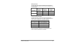
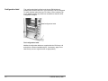
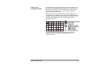
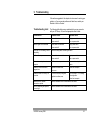
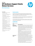
CD Library 144 User’s Guide A-65004 Table of Contents Safety and regulatory information ................................................i Safety and EMC information......................................................iii Declaration of conformity ....................................................iii Safety standards.................................................................iii Canadian interference-causing equipment regulations........ iv Class B ITE ........................................................................ v A-65004 January 1998 1 Introduction..........................................................................1-1 About this manual ..................................................................1-1 Product description ................................................................1-1 Configuring your CD Library 144 ............................................1-3 Catalog numbers....................................................................1-4 2 Product Information.............................................................2-1 Specifications.........................................................................2-1 Performance specifications ....................................................2-2 Environmental specifications ..................................................2-3 Power cables .........................................................................2-4 3 CD Library 144 Features ......................................................3-1 Exterior ..................................................................................3-1 Interior ...................................................................................3-4 4 Magazines.............................................................................4-1 Applying bar code labels ........................................................4-2 Loading CDs in magazine trays ..............................................4-3 Installing magazines in the CD Library....................................4-4 Removing magazines.............................................................4-5 Changing magazines while powered up..................................4-5 5 Setting up the CD Library 144 .............................................5-1 Packaging contents................................................................5-1 Unpacking the library..............................................................5-2 Installing the stabilizing feet....................................................5-2 Installation procedure .............................................................5-2 Connecting the power cable ...................................................5-3 i ii 6 Operating the CD Library 144.............................................. 6-1 Powering up/powering down .................................................. 6-1 Installing media...................................................................... 6-2 Mailbox loading................................................................ 6-2 Magazine loading............................................................. 6-3 Upgrading firmware................................................................ 6-3 Packing/shipping.................................................................... 6-4 7 SCSI Cabling and Configuration......................................... 7-1 SCSI IDs................................................................................ 7-1 Setting SCSI IDs.................................................................... 7-2 SCSI ID Bus length................................................................ 7-2 SCSI harnesses..................................................................... 7-5 Configuration label ................................................................. 7-6 Filling out the Configuration label ..................................... 7-7 Cabling recommendations...................................................... 7-8 SCSI device configuration examples ...................................... 7-9 8 Drive Installation.................................................................. 8-1 Packaging contents................................................................ 8-2 Installation tools ..................................................................... 8-3 EMI shields ............................................................................ 8-3 Installing a drive..................................................................... 8-4 9 Troubleshooting .................................................................. 9-1 Troubleshooting chart ............................................................ 9-1 Indicator light status ............................................................... 9-2 Mechanical error checklist...................................................... 9-3 Warranty and Service Agreement .......................................... 9-5 A-65004 January 1998 Safety and regulatory information Important Safety and Regulatory Information WARNING: TO PREVENT FIRE OR SHOCK HAZARD, DO NOT EXPOSE UNIT TO RAIN OR MOISTURE. TO PREVENT POSSIBILITY OF INJURY OR DAMAGE TO THE UNIT, DO NOT OPERATE WITH ANY COVERS OR PANELS REMOVED. CHANGES OR MODIFICATIONS MADE TO THIS PRODUCT WITHOUT EXPRESS APPROVAL FROM EASTMAN KODAK COMPANY COULD VOID THE USER’S AUTHORITY TO OPERATE THE EQUIPMENT. • Read and follow instructions — Read and follow all the safety and operating instructions before operating the unit. Heed all warnings on the equipment and in the operating instructions. • Power sources — The unit should be operated only from the type of power source indicated on the dataplate label. If you are not sure of the type of power supply that will be used, consult a dealer or local power company. • Power cord damage — Avoid damage to the power cord. If damage should occur, replace it with the specific cord for this unit. • Power cord protection — Power supply cords should be routed so they are not likely to be walked on or pinched by items placed upon or against them. Pay particular attention to cords at plugs, convenience receptacles, and the point where they leave the unit. NOTE: The power cord must have appropriate Safety Agency approval for the country where the unit is installed. • Cleaning — Unplug the unit before cleaning. Clean only the outside cabinets using a damp cloth. Do not use liquid cleaners or aerosol cleaners. • Attachments — Do not use attachments which are not recommended. The use of unrecommended attachments may cause hazards and serious damage to the equipment. • Dust — Excessive dust levels may damage internal parts. • Ventilation — Slots and openings in the cabinets are provided for ventilation and to ensure reliable operation and protection from overheating. The openings should never be blocked or covered and the unit should never be placed near or over a radiator or heat register. Do not place the unit in a built-in installation unless proper ventilation is provided in accordance with the manufacturer’s instructions. A-65004 January 1998 i • Lightning — For added protection for the equipment during a lightning storm, or any time when the equipment will be left unattended and unused for long periods of time, unplug the units from the power outlets. Unplugging the equipment will protect the equipment from damage caused by lightning or power line surges. • Overloading — Do not overload power outlets and extension cords. This can result in a risk of fire or electric shock. • Object or liquid entry — Never push objects of any kind into the equipment openings. They could touch dangerous voltage points or short-out parts and result in a fire or electric shock. Never spill liquid of any kind on the equipment. CAUTION: • Laser safety — See label below: CAUTION: ii Lithium Battery — Danger of explosion if battery powered RAM is incorrectly replaced. Replace only with the same or equivalent type recommended by manufacturer. Dispose of used batteries according to manufacturer’s instructions. Use of controls or adjustments or performance of procedures other than those specified herein may result in hazardous radiation exposure. A-65004 January 1998 Safety and EMC information Declaration of conformity We declare our sole responsibility that the product Kodak Digital Science CD Library 144 to which this declaration relates, is in conformity with the following standards and bears therefore a CE mark: • • • • • EN 55022 ClassB/1994 EN 61000-3-2/1995 EN 61000-3-3/1995 EN 50082-1/1992 EN 90950/1993 following the provisions of the applicable directives: • • 89/336/EEC and amendments 73/23/EEC and amendments Safety standards The Kodak Digital Science CD Library 144 complies with DHHS Regulations 21CFR Chapter I Subchapter J Section 1040.10. The CD Library 144 is in conformity with international safety requirements and bears the following safety marks: • • • UL (Underwriter Laboratories, UL 1950) CSA (Underwriter Laboratories test for Canadian Standards Association, CSA, 22.2 No. 950) GS (TÜV Rheinland, EN 60950) and EN 60825 (IEC825) EMC standards Europe EN 55022:94 Class B emissions EN 61000-3-2 Harmonics EN 61000-3-3 Flicker EN 50082-1:92 Generic Immunity IEC 801-2 IEC 801-3 IEC 801-4 A-65004 January 1998 iii Pacific Rim Region: VCCI (Japan, Class 2) MITI Powerline Requirement Div. 6, No. 378 AS/NZS 3548 (Aus/New Zea. Class B) AS/NZS 4251 (Aus/New Zea.) American Region: 47 CFR part 15 support (FCC Class B), meets Class B limits for verification ICES-003 Issue 2 Rev 1 (Canada, Class B) Canadian interference-causing equipment regulations This Class B digital apparatus meets all requirements of the Canadian Interference-Causing Equipment Regulations. Cet appareil nemérique de la classe B respecte toutes les exigences du Réglement sur le matérial brouilleur du Canada. iv A-65004 January 1998 Class B ITE Translation This is a Class B product based on the standard of the Voluntary Control Council for Interference from Information Technology Equipment (VCCI). If this unit is used near a radio or television receiver in a domestic environment, it may cause radio interference. Install and use the equipment according to the instruction manual. Federal Communications Commission This equipment has been tested and found to comply with the limits for a Class B digital device, pursuant to part 15 of the FCC Rules. These limits are designed to provide reasonable protection against harmful interference in a residential installation. This equipment generates, uses and can radiate radio frequency energy and, if not installed and used in accordance with the instructions, may cause harmful interference to radio communications. However, there is no guarantee that interference will not occur in a particular installation. If this equipment does cause harmful interference to radio or television reception, which can be determined by turning the equipment off and on, the user is encouraged to try to correct the interference by on or more of the following measures: • Reorient or relocate the receiving antenna. • Increase the separation between the equipment and receiver. • Connect the equipment into an outlet on a circuit different from that to which the receiver is connected. • Consult the dealer or an experienced radio/TV technician for help. A-65004 January 1998 v 1 Introduction This Operator’s Manual contains information that will help you set up and use the Kodak Digital Science™ CD Library 144. You do not need any specialized computer knowledge to operate the CD Library 144. About this manual The CD Library 144 accepts both CD-ROM (Read-Only Memory) and CD-R (Recordable) Drives. In this manual they are referred to collectively as drives unless there is a need to differentiate between the two types. Product description The CD Library 144 can store up to 162 CDs in 9 magazines, each containing 18 discs each. You may install up to four CD-ROM or CD-R drives, in any combination. See the section in this chapter entitled, “Configuration options”. Drives and magazines fit interchangeably in the storage bays. However, drives may only be installed in the bottom four storage bays, starting at the lowest bay. You may use any 120mm CD-ROM or CD-R media. For optimum performance and data retention when recording to CDs, Kodak CDWritable media is recommended. A-65004 January 1998 1-1 CDs can be bulk-loaded in magazines or individually loaded through the mailbox. Store up to 162 CDs in 9, 18-disc magazines Your choice of any combination of up to four CD-ROM or CD-R drives The CD Library 144 The CD Library 144 is developed, manufactured, and serviced by Eastman Kodak Company. Device Communications The CD Library 144 robotics and drives are controlled over a singleended Small Computer System Interface (SCSI-2). 1-2 A-65004 January 1998 Configuring your CD Library 144 The following figure illustrates the configuration options for the CD Library 144. Standard CD Library 144 configurations are shipped with the drives installed. You may purchase additional drives at any time and install them yourself. For instructions on how to install drives, see the section entitled “Drive installation” in Chapter 8. Magazines are packed separately from the CD Library 144 and must be installed by the customer. Each magazine can hold up to 18 CDs. You may purchase and install additional magazines at any time. CD media is not included with the CD Library 144. It must be purchased separately. Maximum Storage Options 1 Drive 9 Magazine Bays 162 CDs 2 Drives 8 Magazine Bays 144 CDs 3 Drives 7 Magazine Bays 126 CDs 4 Drives 6 Magazine Bays 108 CDs Standard Configuration Worldwide 2 CD-ROM Drives 8 Magazines 144 CD Capacity Symbol Key CD-ROM or CD-R Drive 18 disc Magazine Configuration options A-65004 January 1998 1-3 Catalog numbers The table below lists the Kodak Digital Science CD Library 144 products with their catalog numbers. Product Name CD Library 144 / Americas CD Library 144 / EAMER CD Library 144 / APR CD Library 144 / Japan CD Library 144 with 8 Magazines and 2 16X CD ROM Drives / Americas CD Library 144 with 8 Magazines and 2 16X CD ROM Drives / EAMER CD Library 144 with 8 Magazines and 2 16X CD ROM Drives / APR CD Library 144 with 8 Magazines and 2 16X CD ROM Drives / Japan CD Library Customer Installable 16X CD-ROM Drive CD Library Customer Installable CD-R 4X / 12X Drive CD Library Factory Installed 16X CD ROM Drive CD Library Factory Installed CD-R 4X/12X Drive CD Library 18-Slot Magazine CD Library Bar Code Labels / #19-#255 1-4 Catalog Number 864 7240 818 8880 172 9185 155 6984 831 4148 115 8443 131 3014 153 2647 812 2483 159 4365 188 4402 146 9873 158 9001 135 3168 A-65004 January 1998 2 Product Information This chapter contains technical information about the CD Library 144. Specifications Physical Characteristics Size (W x H x D) 10.6 x 30.7 x 18.9 in. (270 x 780 x 480mm) Weight, including magazines and discs 70.5 lb. (32 kg) Technical Specifications Maximum disc storage 162 CDs Maximum data storage (650 MB/disc) 105 GB Maximum magazine installation 9 Universal storage bays (drive or magazine) 3 Maximum number of drives CD-R CD-ROM 4 SCSI channels A-65004 January 1998 2 (4, if drives are internally terminated) Operating Voltage 100 — 240V Rating Current 2.5 — 1.0A Frequency 50 — 60Hz 2-1 Performance specifications Disc Exchange Time The CD Library 144 Disc Exchange Time is defined as the time necessary for the robotics to: • pick a disc from a drive (robotics located at the drive, drive drawer open). • move to a magazine and load the disc into the magazine tray. CD Library 144 Disc Exchange Times Maximum Minimum 5.0 seconds 3.7 seconds Average Disc Load Times Method Average Load Time Mailbox — Individual load Magazine — 18 discs/magazine 15 sec./disc 30 sec./magazine Reliability Mean Time Between Failure (MTBF) CD Library 144 Mean Exchanges Between Failures (MEBF) Robotics CD-ROM Drives CD-R Drives Mailbox Magazine Tray 2-2 >20,000 POH (Power on Hours) >2,000,000 >100,000 >75,000 >20,000 >60,000 A-65004 January 1998 Environmental specifications Condition Operating Nonoperating Shipping Temperature Range 41° to 104° F (5° to 40° C) 14° to 149° F -10° to 65° C -40° to 149° F (-40° to 65° C) Gradient 52° F/Hr (11° C/Hr) 68° F/Hr (20° C/Hr) 68° F/Hr (20° C/Hr) Relative Humidity (Non-condensing) 3% to 90% 5% to 95% 5% to 95% Altitude -1000 to 7000 ft. Shock 2Gs @ 11ms half-sine horizontal 1g @ 11ms halfsine vertical axis 50Gs @ 11ms halfsine and 1 pulse. 5-17Hz 0.44mm p-p 5-500Hz, 5mm 1G p-p No damage Vibration 17-150Hz 0.25G No damage 10-20Hz, 2mm p-p 0-p 150-200Hz linear interpolation 200-500Hz 0.33G 0-p Tilt A-65004 January 1998 +/- 5° 2-3 Power cables The power connector on the rear panel of the CD Library 144 complies with IEC 320. The connector on the library end of the power cable must comply with (IEC) EN 60 320/ C13. Depending on your location, the following power cable is provided with the CD Library 144: 2-4 Region Part No. Catalog No. Australia 621 7861 719 3253 Europe Standard 451 3990 719 3204 France/Italy 600 4060 719 3238 Switzerland 603 7200 719 3220 UK 621 7851 719 3246 US/ Mexico/Canada 605 1531 719 3261 Asia/ Pacific Region (APR) Customer provides power cable Greater China Customer provides power cable A-65004 January 1998 3 CD Library 144 Features Exterior This chapter describes the operating features of the CD Library 144. 1 3 2 4 5 6 7 8 9 Exterior features of the CD library 144 1. Indicator lights 6. SCSI connectors 2. Mailbox 7. Stabilizing feet 3. Open/close button, mailbox 8. Power switch 4. Handles 9. Power connector 5. Front door with lock A-65004 January 1998 3-1 Indicator lights — there are three indicator lights on the front of the CD Library 144. See the section entitled, “Indicator light status” in Chapter 9, for an explanation of the lights. From left to right they are: Error (red) Busy (green) Power (green) Mailbox — The mailbox is used for loading and unloading individual CDs. CAUTION: Do NOT use the mailbox drawer to lift or move the CD Library 144! Doing so can damage the drawer and drawer load mechanism. Open/Close Button, Mailbox — press this button to open or close the mailbox. Handles — the handles are used for lifting or moving the CD Library 144. 3-2 A-65004 January 1998 Front door with lock — the front door is unlocked and opened with the key provided. The front door allows access to the interior of the CD Library 144. You need to unlock and open the front door to install or remove magazines and drives, and to set or change SCSI IDs. For firmware versions greater than 1.4.1 — the front door lock can be controlled via the host computer. If the host-controlled lock is enabled, access through the front door is not possible when the unit is powered on, even with a key. If the host-controlled lock is disabled, access through the front door is as described above. The default for the hostcontrolled door lock is disabled. Consult your CD server software documentation for more information. When the front door is opened, an interlock switch disables the robotics after the CD Library 144 completes any tray or drawer operation in progress. Drive operations are not disabled. Front Door Key — two identical keys are provided with the CD Library 144. If you require a replacement key, contact your reseller. SCSI Connectors — the four SCSI connectors, labeled A - D, provide SCSI connections to the CD Library 144 from the host computer Stabilizing feet — the feet provide stability to the CD Library 144 during operation. Power switch — the power switch turns the CD Library 144 on and off Power connector — the power connector provides AC inlet power to the CD Library 144. A-65004 January 1998 3-3 Interior 4 3 7 5 6 2 1 1 For Drives For robotics Detail with A and B EMI Shields removed Interior features of the CD Library 144 1. SCSI ID switches 5. SCSI harnesses 2. EMI shields 6. Power harness 3. Magazine bay 7. Drives 4. Configuration label SCSI ID switches — there is a SCSI ID switch for each of the installed drives and one for the CD Library 144 robotics. Each device on a SCSI bus must be assigned a unique SCSI ID. All SCSI ID switches are identical and each has two push buttons. To increase the SCSI ID number, press the bottom button. To decrease the SCSI ID number, press the top button. 3-4 A-65004 January 1998 EMI shields — the library robotics and each drive are provided with an ElectroMagnetic Interference (EMI) shield. The EMI shields control electromagnetic transmissions or emissions that could interfere with the operation of the drives or the CD Library 144. There are three styles of EMI shields: • A-Style EMI shield — installed on the top or last drive in the CD Library 144. • B-Style EMI shield — installed on all drives except the top one and included with each CD Library customer-installable drive. • C-Style EMI shield — installed over the library robotics and electronics. A-style EMI shield B-style EMI shield C-style EMI shield A-65004 January 1998 3-5 Drive/Magazine bays — there are 10 Drive/Magazine bays. Each bay is identified with one of three labels that indicates what may be installed in that bay, as illustrated below: Configuration label — the configuration label is affixed to the A-style EMI shield and indicates how the SCSI devices in the CD Library 144 are configured. This label should be updated if drives are added or if the SCSI configuration changes. See the section entitled, “Configuration label” in Chapter 7 for instructions on filling out the label. SCSI harnesses — the CD Library 144 supplies four pre-installed SCSI harnesses for connecting the library robotics and drives. See the section entitle “SCSI cabling and configuration” in Chapter 7 for details on the SCSI harnesses. Drive power harness — the power harness has four power connectors, one for each drive position. 3-6 A-65004 January 1998 4 Magazines Kodak Digital Science CD Library 18-Slot Magazines enable you to bulk-load CDs into the CD Library 144. Each magazine contains 18 slide-out trays. Each tray holds one CD. You may purchase additional CD Library 18-Slot Magazines at any time. Contact your sales representative. You can manually load CDs into the magazine trays before you install the magazine in the CD Library 144. Or, empty magazines can be installed in the CD Library 144. If empty magazines are installed, the CDs must be loaded individually through the mailbox and put into the magazine trays, or a drive drawer, through a command from the host software. This chapter describes how to: A-65004 January 1998 • apply bar code labels to magazines • manually load CDs into the magazine trays • install a magazine in the CD Library 144 4-1 Applying bar code labels Magazine bar code labels #1 - 18 are shipped with the CD Library 144. They are provided in sheets of six sets of labels per sheet (two labels per set), and are packed with the manuals and other labels. To order additional bar code labels, contact your reseller. Apply the bar code labels to the magazine before you install it in the CD Library 144. The bar code labels allow the CD Library 144 to identify the magazine during the inventory process. To apply the bar code labels, peel the labels from the sheet and apply to the magazine in the locations noted below. Be sure to apply the labels in the same orientation as illustrated. Applying Bar Code Labels 4-2 A-65004 January 1998 Loading CDs in magazine trays To manually load CDs in the magazine trays: 1. Press the plastic spring on the side of the magazine to unlock the trays, and slide a tray out just far enough to clear the disc area. NOTE: Do not pull the tray completely out of the magazine. If this happens, the tray must be replaced in its original orientation in the magazine. Step 1 Step 2 Loading a CD in the Magazine Tray 2. Place a CD, label side up, in the tray. Make sure the CD sits flat in the disc area. 3. A-65004 January 1998 Press the spring and slide the tray and CD all the way into the magazine. 4-3 Installing magazines in the CD Library You can add magazines to the CD Library 144 or change the position of existing magazines at any time. No tools are necessary for this procedure. NOTE: During the initial set up of the CD Library 144, you must attach the stabilizing feet before installing the magazines (see Chapter 5). 1. Unlock and open the CD Library 144 front door. 2. Determine which bay you wish to use for the magazine. The label on the right side of each bay indicates whether a drive, a magazine, or either, may be installed. 3. Make sure the arrow on the top of the magazine is pointing into the library. Firmly, but carefully, slide the magazine into the bay slot until it clicks into place. CAUTION: Do not use force to push the magazine into the bay slot. Damage to the magazine or your media could result. Finger hole Installation Labels Installing a Magazine 4. 4-4 Close and lock the CD Library 144 front door. A-65004 January 1998 Removing magazines You can remove magazines to the CD Library 144 or change the position of existing magazines at any time. No tools are necessary for this procedure. Changing magazines while powered up You may install or remove magazines while the CD Library 144 is powered up. When you close the front door after installing or removing magazines, the library performs a partial automatic inventory. The inventory records the absence or presence of a CD in the magazines that were changed or added while the door was open. The inventory will take about 30 seconds per changed magazine. NOTE: Opening the front door and changing magazines does not affect drive operations. Any current reading or writing processes will continue while the door is open. A-65004 January 1998 4-5 5 Setting up the CD Library 144 Follow the instructions in this chapter to prepare the CD Library 144 for operation. The only tool you need for these activities is a flat blade screwdriver. Packaging contents The packaging carton contains the following items: • CD Library 144 stabilizing feet • Clear plastic bag containing: Power cable (except in Asia/Pacific Region and Greater China) External SCSI terminator connector (male) Front door keys (2) • Clear plastic bag containing: CD Library 144 Operator’s Manual User’s Manual for each type of installed drive Bar code labels, #1 - 18 Configuration labels (2) Interactive CD — Kodak Business Information Systems Products A-65004 January 1998 5-1 Unpacking the library Retain the packing material in which the CD Library 144 was shipped. You will need it when moving or shipping the unit. CAUTION: Do NOT use the mailbox drawer to lift the CD Library 144! Doing so can damage the drawer and drawer mechanism. Do NOT remove the red retainer strap from the mailbox until after the stabilizing feet have been installed. Installing the stabilizing feet The stabilizing feet must be installed to ensure stability of the CD Library 144. You need a flat head screwdriver to install the stabilizing feet on the bottom of the CD Library 144. NOTE: Do NOT remove the red retainer strap from the mailbox until after the stabilizing feet have been installed. Installation procedure 1. Remove all magazines from the CD Library 144, if any are installed. 2. Place a non-abrasive pad, such as the foam packing material from the shipping carton, on a stable work surface or the floor. The pad will prevent damage to the SCSI connectors and other features on the rear panel of the CD Library 144. 3. Carefully tip the CD Library 144 and lay it on the prepared surface, with the rear panel facing down. 4. Remove the four rubber pads from the bottom of the CD Library 144 by removing the screw that holds each rubber pad. Save the screws. 5-2 A-65004 January 1998 5. Install the stabilizing feet on the bottom of the CD Library 144. Use the four screws removed in Step 4. Installing the Stabilizing Feet 6. Carefully return the CD Library 144 to an upright position. 7. Remove the red retainer strap from the mailbox by withdrawing the tab from the slot and pulling the strap carefully out of the mailbox. The retainer strap keeps the mailbox tray in place during shipping. It must be removed before the CD Library 144 is powered up. NOTE: Keep the retainer strap with the other CD Library 144 packing materials. It must be reinstalled if the unit is moved or shipped. See the section entitled “Packing/Shipping” in Chapter 6 for reinstallation instructions. 8. Install magazines. See the section entitled, “Installing magazines in the CD Library 144” in Chapter 4. Connecting the power cable A-65004 January 1998 Plug the power cable into the power connector on the rear panel of the CD Library 144. 5-3 6 Operating the CD Library 144 This chapter contains operating instructions for the CD Library 144. Powering up/powering down Before powering up the CD Library 144, connect the power cable and SCSI cables, and ensure the last device on each SCSI bus is properly formatted. NOTE: Before you power up the CD Library 144 for the first time after unpacking, remove the red retainer strap from the mailbox if you have not already done so. The retainer strap keeps the mailbox tray in place during shipping. If the retainer strap is still in place when the CD Library 144 is powered up, the automatic inventory will not succeed and damage to the mailbox may result. Power the CD Library 144 up and down with the power switch on the rear panel. Power up procedure Turn the power switch to On. • The CD Library 144 will perform the automatic inventory. During the automatic inventory, all three indicator lights will flash intermittently. • When the inventory is complete and the CD Library 144 is successfully powered up, the green Busy light and green Power light will be illuminated. Automatic inventory Each time the CD Library 144 is powered up, it performs an automatic inventory that records the absence or presence of a CD in each magazine tray, and in the mailbox. It takes about 30 seconds for the CD Library 144 to inventory the CDs in one magazine. A CD Library 144 that is fully loaded with 9 magazines takes approximately 5 minutes to inventory. Power down procedure Turn the power switch to Off. A-65004 January 1998 6-1 Installing media CDs can be loaded into the CD Library 144 in two ways: • • Mailbox loading Individual disc loading through the mailbox. Bulk magazine loading, 18 discs per magazine. To load an individual CD into the CD Library 144: 1. Press the Open/Close button. The mailbox drawer opens. 2. Place the CD in the mailbox tray, label side up. Loading a CD in the Mailbox 3. Press the Open/Close button. The mailbox drawer closes. Each time the mailbox drawer closes, the CD Library 144 robot inventories the mailbox, checking for the absence or presence of a CD in the tray. CAUTION: Always use the Open/Close button to close the mailbox drawer. Do not push on the drawer. NOTE: The CD Library 144 will not move the CD from the mailbox tray unless prompted to do so by the host software. 6-2 A-65004 January 1998 Magazine loading To bulk load CDs into the CD Library 144, see the section entitled “Installing magazines in the CD Library 144” in Chapter 4. Upgrading firmware Firmware upgrades are provided through your reseller or upgrades may be downloaded from the Kodak Web site at: http://www.kodak.com A-65004 January 1998 6-3 Packing/shipping When moving or shipping the CD Library 144, use the original packing material in which it was delivered. Preparing the CD Library 144 for shipping 1. Remove all magazines from the library. Drives may remain installed. 2. Install the mailbox retainer strap: • Power the unit on. • Unlock and open the front door. • Open the mailbox drawer. • Wrap the retainer strap around the front of the mailbox drawer, being sure to include the tray front. Secure the retainer strap by inserting the narrow tab end through the slot. Mailbox tray Mailbox drawer 6-4 • Close the mailbox drawer. • Power the unit off. A-65004 January 1998 7 SCSI Cabling and Configuration All CD Library 144 devices are connected through a single-ended SCSI-2 interface. The CD Library 144 devices include the library robotics and up to four drives. NOTE: There is no direct communication between the library robotics and the installed drives. All coordination between the library robotics and the drives is controlled by the host software. Termination power The CD Library 144 does not provide termination power (TERMPWR) to the SCSI bus. TERMPWR must be provided to the SCSI bus by either the host adapter or the drives. If TERMPWR is not provided, the CD Library 144 may report an error during power up. SCSI IDs As shown in the illustration below, each drive that is installed in a CD Library 144 is assigned a location number, and a recommended default SCSI ID. The CD Library 144 robotics are also assigned a factory default SCSI ID. Location number Drive #4 Drive #3 Drive #2 Drive #1 Robotics Device Default SCSI ID Drive #4 4 Drive #3 3 Drive #2 2 Drive #1 1 Robotics 5 CD Library 144 — Default SCSI IDs A-65004 January 1998 7-1 Setting SCSI IDs There is a SCSI ID switch on each of the installed drives and one for the CD Library 144 robotics. They are located inside the front door and are recessed behind the metal shields (EMI shields) mounted on the drives and robotics. To set the SCSI ID, press the bottom push button to increase the SCSI ID number, and press the top button to decrease the SCSI ID number. Setting SCSI ID switches It is not necessary to remove the EMI shields to set the switches. The switch for the robotics is recessed slightly more than the switches for the drives, but may still be set or changed without removing the EMI shield. Each device on a SCSI bus must have a unique SCSI ID. The CD Library 144 does not support SCSI Configured Automatically (SCAM). SCSI ID Bus length CAUTION: When configuring your CD Library 144, it is critical to keep the total SCSI bus lengths within the limitations set by ANSI specifications. Using longer SCSI buses than specified can create data transfer malfunctions. Use the following formula to determine the total SCSI bus length: Total SCSI bus length = ANSI spec. recommendation = Internal CD Library 144 length + External cable length + Internal host length 7-2 A-65004 January 1998 ANSI Specification The table below lists the maximum allowable SCSI bus lengths as defined by ANSI specifications. The SCSI mode used depends on the host SCSI adapter. SCSI Mode SCSI-2 Fast 20 Maximum SCSI Bus Length Transfer Rate MB/sec. Number of Devices 5 8 19.7 ft. (6m) 10 8 9.8 ft. (3m) 20 4 9.8 ft. (3m) 40 8 4.9 ft. (1.5m) Internal CD Library 144 Length The table below lists the lengths of the internal SCSI harnesses installed in the CD Library 144. The Y-cable is included with each CD Library customer-installable drive, purchased separately. Harness Length A 45.7 in. (1160 mm) B 28 in. (710mm) C 26.4 in. (670mm) D 23.6 in. (600mm) Y-Cable 11.8 in. (300mm) Refer to the illustration CD Library 144—SCSI Harnesses and YCable, No Devices Installed later in this chapter. A-65004 January 1998 7-3 SCSI Cable Requirements The external SCSI cable must be provided by the customer. A shielded single-ended cable with a 50-contact, low density SCSI device connector is required. The cable must comply with the SCSI-2 ANSI X3.131-1994. When laying out the installation site, consider the routing of the I/O cabling. Avoid the following: 7-4 • Static discharges to the cables. • Interference from noise sources such as fluorescent lights, motors, dimmer switches, power lines. A-65004 January 1998 SCSI harnesses For flexibility in configuring your system, the CD Library 144 provides four installed SCSI harnesses. For ease of identification, the harnesses are labeled A - D, both at the connector on the rear panel and on the cable at the opposite connector end. Each CD Library customerinstallable drive includes a Y-cable that can be used for connecting additional devices on a single SCSI bus. Symbol Key External SCSI connector (Female) Internal SCSI Connector (Female) Internal SCSI Connector (Male) 11.8 in (300 mm) Y 9.8 in. (250 mm) Drive Pos 4 SCSI Bus Y-Cable Drive Pos 3 Drive Pos 2 Drive Pos 1 D SCSI connectors on the rear panel C B A SCSI Harness D SCSI Harness C D 21.7 in. (550 mm) C 23.6 in. (600 mm) 26.4 in. (670 mm) SCSI Harness B B 26.4 in. (670 mm) SCSI Harness A Optional Hard Drive (not included) CD Library 144 Robotics 19.7 in. (500 mm) 31.5 in. (800 mm) A Front Rear 28 in. (710 mm) 45.7 in. (1160 mm) CD Library 144 Cabinet CD Library 144—SCSI Harnesses and Y-Cable, No Devices Installed A-65004 January 1998 7-5 Configuration label The configuration label is affixed to the A-style EMI shield and indicates how the SCSI devices in your CD Library 144 are configured. To avoid confusion about how your CD Library 144 is configured, fill out or update the label any time drives are added or when the SCSI configuration changes. Configuration Label The Configuration Label Additional configuration labels are supplied with the CD Library 144 and with the customer-installable drives. If necessary, apply a new label directly over the original and fill out appropriately. 7-6 A-65004 January 1998 Filling out the Configuration label As illustrated below, indicate what devices are on each SCSI bus and where the bus is terminated. Use R to indicate a CD-ROM drive, and W to indicate a CD-R drive. Then, to define the bus, draw a line from the input SCSI connector (A, B, C, or D), through the connected devices, to the termination point. In the example below, the library robotics and a CD-ROM drive (in drive position 1) are installed on the A-SCSI harness, with an external termination at the B connector on the rear panel. A CD-R drive (in drive position 2) is installed on the C-SCSI harness, with an internal termination at the drive. See the SCSI Device Configuration examples at the end of this chapter. Each example includes the appropriately filled out configuration label. A-65004 January 1998 7-7 Cabling recommendations 7-8 To take full advantage of the flexibility of the CD Library 144 SCSI cabling architecture, we recommend the following: • Keep each SCSI bus as short as possible. • The A harness must always be connected in the following way: first to the hard drive (if one is installed), then to the library robotics, then to successive devices if necessary. • Always use the A harness connector as a SCSI input port. • The A harness is the only harness provided that is long enough to connect to a device located in drive Position 4. • Connect the A harness to the last, or top, drive installed. See the cabling examples that follow. • Install drives in the four bottom-most installation bays, starting with drive Position 1. Do not leave empty bays between drives. • Terminate the last device on the SCSI bus. Termination may be made internally or externally, depending on your configuration. An external SCSI terminator connector is provided with the CD Library 144. See drive documentation for procedures on how to terminate drives internally. • To maximize performance and prevent CD-R drive errors, put each CD-R drive on a dedicated SCSI bus. • Assign a unique SCSI ID to each device on a SCSI bus. • Update the Configuration Label each time you add or remove drives or change the SCSI configuration. A-65004 January 1998 The following examples illustrate different drive installation SCSI device configuration examples configurations. Your configuration requirements may be different from what is shown. The SCSI IDs are set as suggested by the CD Library 144 defaults. Symbol Key for Configuration Examples External SCSI connector (Female) Internal SCSI Connector (Female) Internal SCSI Connector (Male) SCSI Terminator Connector (Female/Male), Internal SCSI Terminator Connector (Male), External (provided) External SCSI Bus Input Example 1 — standard configuration Example 1 illustrates the standard SCSI configuration for the CD Library 144, which installs two CD-ROM drives and the library robotics on one SCSI bus. The library robotics and the drives are connected on the same bus, with SCSI input on harness A. The interconnection between the drives is made with a Y-cable. The bus is terminated externally at the B connector on the rear panel. Harnesses C and D are not used here. A-65004 January 1998 7-9 The total length of the internal SCSI cabling in this example is: A + Y + B = 85.5 in. (2172mm) 7-10 A-65004 January 1998 Example 2 Example 2 illustrates the installation of one CD-R drive on a dedicated SCSI bus, and three CD-ROM drives and the library robotics on another bus. The CD-R drive is connected on a separate bus, with SCSI input on harness D. The bus is terminated externally at the C connector on the rear panel. The total length of the internal SCSI cabling on this bus is: C + D = 50 in. (1270mm) The library robotics and three CD-ROM drives are connected on the same bus, with SCSI input on harness A. Interconnections between the drives are made with Y-cables. The bus is terminated externally at the B connector on the rear panel. The total length of the internal SCSI cabling on this bus is: A + Y2 + Y1 + B = 97.2 in. (2470mm) A SCSI ID - 4 CD-ROM Drive Pos 4 SCSI ID - 3 CD-ROM Drive Pos 3 Y2 SCSI ID - 2 Y1 CD-ROM Drive Pos 2 CD-R Drive Pos 1 BUS CDL A B C SCSI ID - 1 T D X B X C D D1 X D2 D3 D4 R R R W Configuration Label for Example 2 SCSI Harness D one bus external termination SCSI Harness C SCSI Harness B one bus external termination SCSI Harness A CD Library 144 Robotics SCSI ID - 5 Front Rear CD Library 144 Cabinet A-65004 January 1998 7-11 Example 3 Example 3 illustrates the installation of two CD-R drives, each connected on a dedicated SCSI bus; and two CD-ROM drives, which share a single SCSI bus with the library robotics. SCSI input for the CD-R drive in drive position 1 is on harness D. The drive is terminated internally. See the drive documentation for information on terminating drives internally. The total length of the internal SCSI cabling on this bus is: D = 23.6 in. (600mm) SCSI input for the CD-R drive in drive position 2 is on harness C. The drive is terminated internally. The total length of the internal SCSI cabling on this bus is: C = 26.4 in.(670mm) The library robotics and two CD-ROM drives are connected on the same bus, with SCSI input on harness A. The interconnection between the drives is made with a Y-cable. The bus is terminated externally at the B connector on the rear panel. The total length of the internal SCSI cabling on this bus is: A + Y + B = 85.5 in. (2172mm) 7-12 A-65004 January 1998 • Close and lock the front door. NOTE: The mailbox drawer must be secured to prevent the tray from sliding out of the mailbox during shipping. If you do not have the original retainer strap, a strip of heavy weight paper may be substituted. Tape or staple the strip to secure. 3. Unplug the power and SCSI cables from the rear panel. 4. Remove the stabilizing feet. A-65004 January 1998 • Place a non-abrasive pad, such as the foam packing material from the shipping carton, on a stable work surface or the floor. • Carefully tip the CD Library 144 and lay it on the prepared surface, with the rear panel facing down. • Remove the stabilizing feet from the bottom of the CD Library 144 by removing the screws. • Carefully return the CD Library 144 to its upright position. 6-5 5. Pack the CD Library 144 in its original packing container. Make sure both the top and bottom pieces of molded foam packing material are in place before sliding the carton top over the unit. 6. Securely fasten the carton closed with the plastic handles, as illustrated below. Carton top 6-6 A-65004 January 1998 8 Drive Installation You may purchase additional CD-ROM or CD-R drives for your CD Library 144. There are currently two drives available for field installation by the customer: • Kodak Digital Science CD Library Customer Installable 16X CD-ROM Drive. • Kodak Digital Science CD Library Customer Installable CD-R 4X/12X Drive. Contact your reseller for the latest list of available drives. Most packaging, shipping, and installation procedures are the same for both types of drives. Therefore, they are collectively referred to here as drives, unless it is necessary to differentiate between the two types. There may be slight differences in the SCSI configurations of a CD-R and a CD-ROM Drive. IMPORTANT: See Chapter 7, “SCSI Cabling and Configuration” for more information.. This chapter describes the drive packaging contents and provides instructions for installing a drive into the CD Library 144. A-65004 January 1998 8-1 Packaging contents 4 5 2 1 3 Contents of customer-installable drive package 1. Customer Installable Drive (with mounting brackets installed) 2. EMI shield, B style, with fastener 3. Y-Cable 4. User’s Manual—Drive 5. Configuration label 6. Installation Instructions (not pictured) 7. 8-2 Kodak CD Writable media (not pictured), with CD-R Drive only A-65004 January 1998 Installation tools The only tool you need to install a Customer Installable Drive in a CD Library 144 is a flat blade screwdriver. EMI shields Each drive is provided with an EMI (ElectroMagnetic Interference) shield. The EMI shields protect the CD Library 144 from harmful electromagnetic transmissions and emissions. CAUTION: To ensure EMI/EMS (EMS = ElectroMagnetic Susceptibility) protection, the EMI shields must be reinstalled after changing drives or modifying the drive harness. There are three styles of EMI shields for the CD Library 144: • The A-style shield is provided with the CD Library 144 and is always installed on the last or top, drive. • B-style shields protect all other drives. One B-style shield is included with each Customer Installable Drive. The C-style shield is provided with the CD Library 144 and protects the library robotics and electronics. A-style EMI shield B-style EMI shield C-style EMI shield Three styles of EMI shields A-65004 January 1998 8-3 Installing a drive NOTE: A bar code label is installed on the Customer Installable Drive chassis. Do not change or remove this label. Drive installation procedure 1. Power down the host computer, the CD Library 144, and all connected SCSI devices. 2. Unplug the power cable from the back of the CD Library 144. 3. Unlock and open the front door. 4. Remove the A-style EMI shield from the top drive in the library by removing the screw that secures the right side of the shield. Swing the shield open and remove the left side of the shield from the tab in the library frame. 5. Remove the remaining EMI shields in t he same manner, starting at the top and working down. NOTE: The screws that secure the EMI shields also secure the drive to the library frame. Be sure to retain the screws for reinstallation of the EMI shields. This screw secures both the EMI shield and the drive. Removing the A-Style EMI shield 8-4 A-65004 January 1998 6. If a magazine is installed in the bay directly above the top installed drive, remove it and re-install it in an empty bay. Drives may be installed in the four lowest bays only, starting with the bottom, with no empty bays between drives. 7. Hold the drive as illustrated below and firmly but carefully slide it into the bay slot until it clicks into place. Installing a drive The CD Library 144 comes equipped with two SCSI ID harnesses. (Early versions of the CD Library 144 do not have SCSI ID harnesses and this step should be disregarded for those units.) These harnesses connect the drives to the library control board and provide the capability for the library to communicate drive positions and drive SCSI IDs to the host. One end of the two harnesses connects to the robotics control board at the bottom of the library. Each opposite end consists of two connectors for connecting to the installed drives. One harness has connectors labeled 1 and 2 for installation to drives in positions one and two and the other have connectors labeled 3 and 4 for installation to drives in positions three and four. A-65004 January 1998 8-5 8. There are four SCSI harnesses installed in the CD Library 144. Choose the appropriate harness and connect it to the SCSI connector on the back of the drive. You may need to use the Ycable for the drive’s SCSI bus connection, depending on your configuration. For SCSI cabling information and examples, see the section entitled, “SCSI cabling and configuration” in Chapter 7. 9. Terminate the SCSI bus appropriately. The last device on the SCSI bus must be terminated. Termination may be made internally or externally, depending on your configuration. See the diagram with Step 12 or the drive documentation for procedures on how to internally terminate drives. 10. The CD Library 144 provides four power connectors. Plug one of the power connectors into the back of the drive. Use any one of the available connectors. SCSI Harness Power Harness SCSI ID Switch SCSI ID harness not shown Cable Harnesses 8-6 A-65004 January 1998 11. Re-install the bottom C-style EMI shield in its original lowest position. Working form the bottom up, install B-style, EMI shields over all drives except the top-most drive. Finally, install the A-style EMI shield over the top drawer. Configuration label A-style EMI shield B-style EMI shield Drive and EMI Shields Installed 12. Set the drive SCSI ID switch, if necessary. See the section entitled, “Setting SCSI IDs” in Chapter 7 for system default IDs. Each device on a SCSI bus must be assigned a unique SCSI ID. A-65004 January 1998 8-7 NOTE: Drives are shipped with the SCSI ID switch already connected to the back of the drives. Should this connection be inadvertently disconnected from the back of the drive, see the following diagram for proper reconnection. Writer: Teac CD-R50S not terminated Red Wire terminated 0 1 2 3 4 5 6 7 0 1 2 3 4 5 6 7 l l O l l l l l l l O l l l l l l l l l l l l l l l l l l l l l CD-ROM: Teac CD-516S Red Wire terminated not terminated Red Wire 0 1 2 3 4 5 6 7 0 1 2 3 4 5 6 7 l l l l l l l l l l l l l l l l l l O l l l l l l l O l l l l l Red Wire 13. Update the configuration label located on the A-style EMI shield. See the section entitled “Filling out the configuration label” in Chapter 7 for more information. 14. Close and lock the CD Library 144 front door. 15. Plug the power cable into the back of the CD Library 144. 8-8 A-65004 January 1998 9 Troubleshooting If the actions suggested in this chapter do not succeed in solving your problem, or if you encounter problems not listed here, contact your Reseller or Service Provider. Troubleshooting chart The following table lists common problems that you may encounter with your CD Library 144, and the appropriate action to take. Problem/Error Probable Cause Operator Action Unit does not power up Power cable not connected Plug in power cable Power switch off Turn on power switch Power cable not connected Plug in power cable Power switch off Turn on power switch Indicator lights do not illuminate Error light is on or flashing, unit not responding See the following table, Indicator Light Status Mailbox will not open Power cable not connected Plug in power cable Power switch off Turn on power switch Automatic inventory does not complete Mailbox retainer strap not removed Remove retainer strap from mailbox drawer Unable to retrieve documents, images, data Application software error, Reboot host computer Unable to access CD Library 144 from host SCSI bus incorrectly configured Drive error Application software error Refer to Chapter 7, SCSI cabling and configuration Reboot host computer Mechanical error, manual intervention required Refer to Mechanical Error Checklist later in this section Unit not responding as expected, no error light Refer to Mechanical Error Checklist later in this section A-65004 January 1998 9-1 Indicator light status There are three indicator lights on the front of the CD Library 144. From left to right they are Error (red), Busy (green), and Power (green). The following table describes the different states of the indicator lights, and the appropriate action to take if an error occurs. Indicator Light Status Error red Busy green Power green System Status Operator Action off off off Power off No action necessary off on on System ready No action necessary off flash on System busy No action necessary flash off on System error Power down unit, power back up on off on Firmware error or power up error Power down unit, power back up. If unsuccessful, install new firmware. Refer to Chapter 5, Upgrading Firmware. on on on SCSI bus error Power down unit, power back up. Check configuration, terminate SCSI bus. Refer to Chapter 5, SCSI cabling and configuration. on flash on Front door open Close and lock front door flash flash on Power up error Power down unit, power back up. Blocked clear path sensor Mechanical error, manual intervention required Refer to Chapter 9, Mechanical error checklist. 9-2 A-65004 January 1998 Mechanical error checklist If a mechanical error occurs, perform the following checklist. It addresses the most common reasons for a mechanical error or jam. • Close and lock the front door. • Open the mailbox and check that the tray is fully seated. • Close the mailbox. • Power down the unit and unplug the power cable. • Open the front door, remove all magazines, and check that all of the magazine trays are fully closed and seated. With the magazines removed, locate the picker assembly, pictured below. It is located inside the unit, behind the magazine/drive bay area. It travels up and down on two shafts: one is round and spiraled, and the other is square. The shafts are mounted near the right hand, inside panel of the CD Library 144. Picker Assembly The Picker Assembly • A-65004 January 1998 Move the picker up or down by manually rotating the spiraled shaft. Position the picker at or near magazine bay 8. 9-3 • If there is a CD being held by the picker, as in the picture below, release the CD by doing the following: With your left hand, hold the CD lightly by the edges. With your right hand, push the white tab feature (see below) away from you. The picker releases the CD. White tab, push here CD Releasing the CD 9-4 • Reinstall the magazines. • Close and lock the front door of the CD Library 144. • Plug in the power cable and power up the unit. • If the original problem persists, contact your Reseller or Service Provider. A-65004 January 1998 Warranty and Service Agreement Important Warranty and Service Agreement Notice: To avoid unnecessary down-time should your Kodak Digital Science CD Library 144 need service, it is important to register your Warranty as soon as possible. Contact your CD Library 144 Reseller to register your warranty and discuss your Service Agreement protection options. Be sure to have the Serial Number and K# of the CD Library 144 ready when you contact your Reseller. A-65004 January 1998 9-5 EASTMAN KODAK COMPANY Business Imaging Systems Rochester, New York 14650 Kodak, Digital Science and the ds monogram symbol, are trademarks of Eastman Kodak Company. Printed on recycled paper. A-65004 1/98 Eastman Kodak Company, 1998 Printed in U.S.A. BUSINESS I M AG I NG SYSTEMS