1
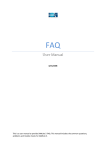
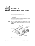
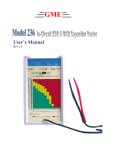
CHAPTER 7
Checking Inside the System
This chapter provides troubleshooting procedures for components inside the system.
Before you start any of the procedures in this chapter, take the following steps:
•
•
Perform the procedures described in “Checking Connectors and Switches” in
Chapter 2.
Read the safety instructions in “Safety First—For You and Your System” in the
next section of this chapter.
You need your system’s User's Guide to perform the procedures in this chapter.
NOTE: When you see the question “Is the problem resolved?” in a troubleshooting
procedure, perform the operation that caused the problem.
Safety First—For You and Your System
The procedures in this guide require that you open the system cover and work inside
the system. While working inside the system, do not attempt to service the system
except as explained in this guide and elsewhere in Dell documentation. Always follow
the instructions closely. See the safety instructions in your Dell PowerEdge System
Information document for important safety information.
WARNING FOR YOUR PERSONAL SAFETY AND PROTECTION OF THE
EQUIPMENT
Before starting to work on the system, perform the following steps in the
sequence listed:
support.dell.com
1.
Power off and disconnect your system and peripherals from their power
sources (unless you are installing or removing a hard-disk drive). Also,
disconnect any telephone or telecommunication lines from the system.
2.
Ground yourself by touching an unpainted metal surface on the
chassis, such as the metal around the card-slot openings at the back of
the system, before touching anything inside your system.
3.
While you work, periodically touch an unpainted metal surface on the
system chassis to dissipate any static electricity that might harm
internal components.
Checking Inside the System
7-1
In addition, Dell recommends that you periodically review the safety instructions for
this system.
Removing and Replacing the Optional
Front Bezel
You must remove the system’s optional front bezel before removing the system from
the rack, installing or removing a hard-disk drive, or using the diskette or CD-ROM
drive.
Removing the Optional Front Bezel
To remove the front bezel, press the retention tab on each end of the bezel and
remove the bezel from the chassis (see Figure 7-1).
nameplate
tabs (2)
Figure 7-1. Removing the Bezel
Replacing the Optional Front Bezel
To replace the front bezel, insert the retention tabs on each end of the bezel and press
the bezel toward the chassis until it locks into place (see Figure 7-1). Ensure that the
bezel is oriented so that its status indicators are positioned just above the Dell
nameplate in the center of the bezel.
Opening the System Cover
WARNING: The power supply in your system may produce high voltages
and energy hazards, which can cause bodily harm. Only trained service
technicians are authorized to remove the cover and access any of the
components inside the system chassis.
7-2
Installation and Troubleshooting Guide
The system has a cover that provides access to the system board, memory, installed
drives, and expansion cards.
To open the system cover, perform the following steps.
CAUTION: Observe the precautions in “Safety First—For You and Your
System.” Also observe the safety instructions in your System Information
document.
1.
Unscrew the captive screw fasteners securing the system to the rack.
2.
Slide the system out of the rack.
3.
Using a Phillips screwdriver, remove the screw securing the cover to the front
panel (Figure 7-2).
4.
Slide the top cover back and lift the cover up and off the system chassis.
cover
screw
Figure 7-2. Opening the System Cover
Replacing the System Cover
NOTE: When sliding the system back into the rack, ensure that none of the internal
wiring or cables interferes with the cover.
To replace the cover, perform the following steps:
support.dell.com
1.
Lower the cover over the system chassis with the hole facing forward (towards
the front panel).
2.
Engage the notches in the cover into mating fingers on the inside of the chassis.
3.
Slide the cover forward until the hole in the cover aligns with a matching hole in
the front of the chassis.
Checking Inside the System
7-3
4.
Secure the cover with the screw you removed when you opened the cover (see
Figure 7-2).
Inside the System
In Figure 7-3, the cover is removed to provide an interior view. Figure 7-3 also
identifies the drive bays. Use this illustration to locate interior features and
components discussed later in this guide.
riser board
control panel cable
IDE-SEC interface cable
PCI retention panel
microprocessor
and heat-sink
memory modules (up to 4)
IDE-PRI interface cable
cooling fans (5)
power supply
CD-ROM
drive
diskette
drive
hard-disk drives (2)
control panel
Figure 7-3. Inside the System
The system board holds the system's control circuitry and other electronic
components. Several hardware options such as the microprocessor and memory are
installed directly on the system board.
The expansion card riser board accommodates one full-length peripheral component
interconnect (PCI) expansion card and one low-profile PCI card (occupied by the video
controller).
The peripheral bays provide space for an integrated 3.5-inch diskette drive and
CD-ROM drive, and two 1-inch hard-disk drives. For more information, see Chapter 9,
“Installing Drives”.
The power cables leading from the power supply distribute power to the system
board and all installed drives.
For drives such as the diskette drive and the CD-ROM drive, an interface connector
connects each drive to the system board.
7-4
Installation and Troubleshooting Guide
Troubleshooting a Wet System
Liquid spills, splashes, and excessive humidity can cause damage to the system. If an
external device (such as an external drive) gets wet, contact the device manufacturer
for instructions. If the system gets wet, perform the following steps:
1.
Power off the system, including any attached peripherals, and disconnect the
system from the electrical outlet.
NOTICE: See “Protecting Against Electrostatic Discharge” in the safety
instructions in your System Information document.
2.
Open the system cover.
3.
Let the system dry for at least 24 hours.
Make sure that it is thoroughly dry before proceeding.
4.
Remove all expansion cards installed in the system.
See “Removing an Expansion Card” in Chapter 8.
5.
Close the system cover, reconnect the system to the electrical outlet, and power
on the system.
Does the system have power?
Yes. Go to step 6.
No. See Chapter 10, “Getting Help,” for instructions on obtaining technical
assistance.
6.
Power off the system, disconnect it from the electrical outlet, open the system
cover, and reinstall all expansion cards you removed in step 4.
7.
Close the system cover and reconnect the system to the electrical outlet.
8.
Run the Dell Diagnostics and test the system.
Did the tests run successfully?
Yes. The system is operating properly.
No. See Chapter 10, “Getting Help,” for instructions on obtaining technical
assistance.
support.dell.com
Checking Inside the System
7-5
Troubleshooting a Damaged System
If the system was dropped or damaged while being moved, you should check the
system to see if it functions properly. If an external device attached to the system is
dropped or damaged, contact the manufacturer of the device for instructions or see
Chapter 10, “Getting Help,” for information on obtaining technical assistance from
Dell.
To troubleshoot a damaged system, perform the following steps:
1.
Power off the system, including any attached peripherals, and disconnect the
system from its electrical outlet.
NOTICE: See “Protecting Against Electrostatic Discharge” in the safety
instructions in your System Information document.
2.
Open the system cover.
3.
Check the expansion-card connections to the riser board and PCI2 connector on
the system board.
4.
Verify all internal cable and component connections.
Make sure that all cables are properly connected and that all components are
properly seated in their connectors and sockets.
5.
Close the system cover and reconnect the system to the electrical outlet.
6.
Run the system board tests in the Dell Diagnostics.
Did the tests run successfully?
Yes. The system is operating properly.
No. See Chapter 10, “Getting Help,” for instructions on obtaining technical
assistance.
Troubleshooting the Battery
If an error message indicates a problem with the battery, or if the System Setup
program loses the system configuration information when the system is turned off,
the battery may be defective.
To troubleshoot the battery, perform the following steps:
1.
Power off the system, including any attached peripherals, and disconnect the
system from its electrical outlet.
NOTICE: See “Protecting Against Electrostatic Discharge” in the safety
instructions in your System Information document.
2.
7-6
Open the system cover.
Installation and Troubleshooting Guide
3.
Check the connection of the coin cell battery to the system board.
See “Replacing the Battery” in Chapter 8, “Installing System Board Options,” for
information on gaining access to the battery socket.
4.
Is the battery firmly installed in the battery socket on the system board?
Yes. Go to step 7.
No. Go to step 6.
5.
Reseat the battery in its socket.
6.
Close the system cover and reconnect the system to the electrical outlet.
Is the problem resolved?
Yes. The battery was loose. You have fixed the problem.
No. Continue with this procedure.
CAUTION: There is a danger of a new battery exploding if it is incorrectly
installed. Replace the battery only with the same or equivalent type
recommended by the manufacturer. Discard used batteries according to the
manufacturer's instructions.
7.
Repeat steps 1 and 2.
8.
Replace the battery.
Is the problem resolved?
Yes. The battery's charge was low. You have fixed the problem.
No. See Chapter 10, “Getting Help,” for instructions on obtaining technical
assistance.
Troubleshooting the Power Supply
The green light-emitting diode (LED) on the control panel (see Figure 2-4) signals the
system power status. The LED is normally green when the system is on and running.
Replace the power supply as described in the following subsection.
WARNING: The power supply in your system may produce high voltages
and energy hazards, which can cause bodily harm. Only trained service
technicians are authorized to remove the cover and access any of the
components inside the system chassis.
support.dell.com
Checking Inside the System
7-7
Power Supply Removal and Replacement
To remove a power supply, perform the following steps.
CAUTION: Observe the precautions in “Safety First—For You and Your
System” presented earlier in this chapter. Also observe the safety instructions in your System Information document.
CAUTION: The microprocessor and heat-sink assembly and other system
board components can get extremely hot during system operation. Be sure
the system has had sufficient time to cool before you touch it.
NOTICE: See “Protecting Against Electrostatic Discharge” in the safety
instructions in your System Information document.
CAUTION: Avoid touching the output connectors on the power supply. Wait
10 to 20 seconds after disconnecting the AC power cable from its input
receptacle before removing the power supply or coming into contact with
its output connectors.
7-8
1.
Unplug the power cord and all peripheral cables from the back of the system.
2.
Remove the system cover.
3.
Disconnect the DC power cable from its connector on the system board.
4.
Disconnect the DC power cable from the hard-disk drives.
5.
Disconnect the DC power cable from the back of the 3.5-inch diskette drive and
the CD-ROM drive.
6.
Remove the two screws that secure the power supply to the chassis back panel
(see Figure 7-4).
7.
Lift the power supply out of the chassis.
Installation and Troubleshooting Guide
power supply
screws (2)
Figure 7-4. Power Supply Removal
To install a replacement power supply, perform the following steps:
1.
Lower the new power supply into the chassis.
Ensure that the power supply is properly seated into its slot in the chassis.
support.dell.com
2.
Secure the power supply with the two screws removed in step 6 of the previous
procedure.
3.
Connect the DC power cables to their connectors on the system board, hard-disk
drives, and CD-ROM drive.
4.
Replace the cover.
5.
Connect the AC power cable to the power input receptacle on the back panel of
the system.
6.
Connect the free end of the AC power cable to an electrical outlet.
7.
Connect all peripheral cables to the back of the system.
8.
Power on the system and observe the front-panel status indicators for normal
operation.
Checking Inside the System
7-9
Troubleshooting a Cooling Fan
Five cooling fans are installed in the system chassis. (See Figure 7-5 for fan
orientation. Fan 1 is the outermost fan in the fan assembly, located directly behind the
CD-ROM drive.) If you observe that one of the cooling fans is not operating or if the
Dell Diagnostics software issues a fan-related error message, perform the following
steps to replace the faulty fan.
CAUTION: Observe the precautions in “Safety First—For You and Your
System” presented earlier in this chapter. Also observe the safety
instructions in your System Information document.
NOTICE: See “Protecting Against Electrostatic Discharge” in the safety
instructions in your System Information document.
1.
Power off the system, including any attached peripherals, and disconnect the AC
power cable from its power source.
2.
Remove the system cover.
3.
Disconnect the cooling fan power cable by pressing the release tab on the power
cable connector.
NOTE: Perform the next step only if you are removing fan 1, located behind the
CD-ROM drive. If you are replacing any other fan, skip to step 5.
7-10
4.
If you are removing fan 1, you must remove two screws that secure the fan to its
bracket.
5.
Lift the fan out of the system chassis (see Figure 7-5).
Installation and Troubleshooting Guide
fan power cable
cooling fans (5)
fan power connectors
Figure 7-5. Removing a Cooling Fan
NOTICE: When installing a new fan, ensure that the airflow arrow on the
fan is pointing to the rear of the system. If the fan is installed incorrectly,
system components might be damaged due to overheating.
NOTICE: Ensure that the fan’s wiring harness is routed from the side of the
fan when the fan is installed. If the fan’s wiring harness is routed from the
top or the bottom of the fan, the cover will not close properly and the fan or
the wiring harness might be damaged.
6.
Press the new fan into its position in the chassis and connect the fan power
connector to a vacant fan power connector in the system board (see Figure 7-5).
Ensure that the replacement fan is oriented the same way as the original fan.
If you are replacing the fan directly behind the CD-ROM drive, secure the fan with
the two screws you removed with the old fan.
7.
When reinstalling the fan, be careful to avoid pinching the system interface
cables.
8.
Replace the cover and reconnect the system to AC power.
9.
Power on the system. Do the fans operate properly?
Yes. You have fixed the problem.
No. See Chapter 10, “Getting Help,” for instructions on obtaining technical
assistance.
support.dell.com
Checking Inside the System
7-11
Troubleshooting Expansion Cards
If an error message indicates an expansion-card problem or if an expansion card
seems to perform incorrectly or not at all, the problem could be a faulty connection, a
conflict with software or other hardware, or a faulty expansion card. To troubleshoot
expansion cards, perform the following steps:
1.
Power off the system, including any attached peripherals and disconnect the AC
power cable from its power source.
NOTICE: See “Protecting Against Electrostatic Discharge” in the safety
instructions in your System Information document.
2.
Open the system cover.
See “Opening the System Cover” presented earlier in this chapter.
3.
Remove the expansion card.
See “Removing an Expansion Card” in Chapter 8.
4.
If the removed expansion card was installed on the riser board, remove the riser
board.
See “Removing and Replacing the Riser Board” in Chapter 8.
5.
If the expansion card uses the riser board, reinstall the riser board.
See “Removing and Replacing the Riser Board” in Chapter 8.
6.
Reinstall the expansion card.
See “Installing an Expansion Card” in Chapter 8.
7.
Close the system cover, reconnect the system to AC power, and power on the
system.
Is the problem resolved?
Yes. The riser board or expansion card connections were loose. You have fixed
the problem.
No. Go to step 8.
8.
Remove all expansion cards from the system.
See “Removing an Expansion Card” in Chapter 8.
9.
Run the system memory test in the Dell Diagnostics.
Did the test run successfully?
Yes. Go to step 10.
No. See Chapter 10, “Getting Help,” for information on obtaining technical
assistance.
7-12
Installation and Troubleshooting Guide
10. Power off the system, disconnect it from AC power, and open the system cover.
11. Reinstall one of the expansion cards you removed in step 8.
12. Run the system memory test in the Dell Diagnostics.
Did the test run successfully?
Yes. Go to step 13.
No. See Chapter 10, “Getting Help,” for information on obtaining technical
assistance.
13. Repeat steps 11 and 12 for the remaining expansion card that you removed in
step 8.
Have you reinstalled all of the expansion cards without encountering a test
failure?
Yes. You have fixed the problem.
No. See Chapter 10, “Getting Help,” for information on obtaining technical
assistance.
Troubleshooting System Memory
A system memory problem can be a faulty dual in-line memory module (DIMM) or a
faulty system board. If a random-access memory (RAM) error message appears, the
system probably has a memory problem.
When you power on or reboot the system, the Caps Lock and Scroll Lock indicators
on the keyboard should flash momentarily and then remain off. If the Num Lock
category in the System Setup program is set to On, the Num Lock indicator should
flash momentarily and then remain on; otherwise, it should remain off. Abnormal
operation of these indicators can result from a defective DIMM.
To troubleshoot system memory, perform the following steps:
1.
Power on the system, including any attached peripherals.
Is there an error message indicating invalid system configuration information
after the memory count is completed?
Yes. Go to step 2.
No. Go to step 7.
support.dell.com
Checking Inside the System
7-13
2.
Enter the System Setup program to check the system memory setting.
See “Using the System Setup Program,” in your User's Guide for instructions.
Does the amount of memory installed match the system memory setting?
Yes. Go to step 8.
No. Go to step 3.
3.
Power off the system, including any attached peripherals, and disconnect the
power cable from the electrical outlet.
NOTICE: See “Protecting Against Electrostatic Discharge” in the safety
instructions in your System Information document.
4.
Open the system cover.
5.
Reseat the DIMMs in their sockets.
6.
Close the system cover, reconnect the system to AC power, and power on the
system.
7.
Enter the System Setup program and check the system memory again.
Does the amount of memory installed match the system memory?
Yes. Go to step 8.
No. Go to step 9.
8.
Reboot the system, and observe the monitor screen and the Num Lock, Caps
Lock, and Scroll Lock indicators on the keyboard.
Does the monitor screen remain blank, and do the Num Lock, Caps Lock, and
Scroll Lock indicators on the keyboard remain on?
Yes. Go to step 9.
No. Go to step 14.
9.
Repeat steps 3 and 4.
NOTE: There are multiple configurations for the DIMMs. See “Memory Module
Installation Guidelines,” in Chapter 8. The following steps are an example of one
configuration.
10. Swap the DIMM in DIMM_0 with one of the same capacity.
11. Close the system cover and reconnect the system to an electrical outlet.
7-14
Installation and Troubleshooting Guide
12. Reboot the system, and observe the monitor screen and the indicators on the
keyboard.
Is the problem resolved?
Yes. You have fixed the problem.
No. Go to step 13.
13. Repeat steps 10 through 12 for each DIMM installed.
Is the problem resolved?
Yes. You have fixed the problem.
No. Go to step 14.
14. Run the system memory test in the Dell Diagnostics.
Did the test run successfully?
Yes. You have fixed the problem.
No. See Chapter 10, “Getting Help,” for instructions on obtaining technical
assistance.
Troubleshooting the Video Subsystem
Troubleshooting video problems involves determining which of the following items is
the source of the problem: the monitor, the monitor interface cable, the video
memory, or the video logic of the system.
The following procedure troubleshoots problems with the video memory and video
logic only. Before you begin, perform the procedure in “Troubleshooting the
Monitor” in Chapter 6, “Checking the Equipment,” to determine whether or not the
monitor is the source of the problem.
To troubleshoot the video subsystem, run the video tests in the Dell Diagnostics.
Did the tests run successfully?
Yes. The problem is not related to video hardware. Go to Chapter 4, “Finding
Software Solutions.”
No. The integrated video controller is faulty. See Chapter 10, “Getting Help,” for
instructions on obtaining technical assistance.
support.dell.com
Checking Inside the System
7-15
Troubleshooting the System Board
A system board problem can result from a defective system board component, a
faulty power supply, or a defective component connected to the system board. If an
error message indicates a system board problem, perform the following steps to
troubleshoot the problem:
1.
Power off the system, including any attached peripherals, and disconnect the
system from its electrical outlet.
NOTICE: See “Protecting Against Electrostatic Discharge” in the safety
instructions in your System Information document.
2.
Open the system cover.
3.
Remove all expansions cards. See “Removing an Expansion Card” in Chapter 8.
4.
Close the system cover, reconnect the system to AC power, and power on the
system.
5.
Run the system board tests in the Dell Diagnostics.
Did the tests run successfully?
Yes. Go to step 6.
No. See Chapter 10, “Getting Help,” for instructions on obtaining technical
assistance.
6.
Power off the system and disconnect it from AC power.
7.
Reinstall one of the expansion cards that you removed in step 3, repeat step 4,
and continue with step 8.
8.
Run the system board tests again.
Did the tests run successfully?
Yes. Go to step 9.
No. See Chapter 10, “Getting Help,” for instructions on obtaining technical
assistance.
9.
Repeat steps 6 through 8 for the remaining expansion card that you removed in
step 3.
Have you reinstalled all of the expansion cards without a test failure?
Yes. You have fixed the problem.
No. One of the expansion cards is faulty. See Chapter 10, “Getting Help,” for
instructions on obtaining technical assistance.
7-16
Installation and Troubleshooting Guide
Troubleshooting the Diskette Drive
Subsystem
If the monitor displays a system error message indicating a diskette drive problem
during execution of either the boot routine or the Dell Diagnostics, the problem may
be caused by any of the following conditions:
•
•
•
•
•
An expansion card is interfering with proper drive operations.
The diskette drive/CD-ROM drive cables are not firmly connected.
The diskette drive is faulty.
The system's power supply is not providing sufficient power for the drives.
The system's diskette drive logic is faulty.
To troubleshoot the diskette drive subsystem, perform the following steps:
1.
Enter the System Setup program, and verify that the diskette drive setting is
configured correctly.
See “Using the System Setup Program,” in the User's Guide for instructions.
2.
Run the diskette drive test in the Dell Diagnostics to determine whether the
diskette drive subsystem now works correctly.
Do the tests complete successfully?
Yes. You have fixed the problem.
No. Go to step 3.
3.
Power off the system, including any attached peripherals, and disconnect the AC
power cable from its power source.
4.
Open the system cover.
NOTICE: See “Protecting Against Electrostatic Discharge” in the safety
instructions in your System Information document.
5.
Remove all expansion cards from the system.
6.
Close the system cover, reconnect the system to AC power, and power on the
system.
7.
Run the diskette drive test in the Dell Diagnostics to determine whether the
diskette drive subsystem now works correctly.
Do the tests complete successfully?
Yes. An expansion card may be conflicting with the diskette drive logic, or you
may have a faulty expansion card. Go to step 8.
No. The diskette drive subsystem is faulty. See Chapter 10, “Getting Help,” for
instructions on obtaining technical assistance.
support.dell.com
Checking Inside the System
7-17
8.
Reinstall one of the expansion cards that you removed in step 5, and repeat
steps 6 and 7.
9.
Close the system cover, reconnect the system to AC power, and power on the
system.
10. Run the diskette drive tests in the Dell Diagnostics to determine whether the
diskette drive subsystem now works correctly.
11. Repeat steps 8 through 10 until all expansion cards have been reinstalled or until
one of the expansion cards prevents the system from booting from the
diagnostics diskette.
12. Has an expansion card prevented the system from booting from the diagnostics
diskette?
Yes. An expansion card is faulty. See Chapter 10, “Getting Help,” for instructions
on obtaining technical assistance.
No. The diskette drive subsystem is faulty. See Chapter 10, “Getting Help,” for
instructions on obtaining technical assistance.
Troubleshooting Hard-Disk Drives
If you have hard-disk drive problems, perform the following checks:
7-18
1.
Back up the files on your hard-disk drive.
2.
Run the appropriate integrated drive electronics (IDE) hard-disk drive tests as
described in Chapter 5, “Running the Dell Diagnostics.”
3.
If necessary, see See Chapter 10, “Getting Help,” for instructions on obtaining
technical assistance.
Installation and Troubleshooting Guide