1
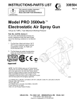
Service and
Troubleshooting
Manual
-12/20/06-
© Handi Quilter, LLC.
Table of Contents
About the HQ Sixteen
About the manual
Service Manual General Rules
General Specifications (I)
Lubrication Specifications (II)
Adjustments:
Page
Lubrication Instructions………………………………………………..…………0.1 – 0.4
General Observation of Front Frame Cover, Mast and Hand Wheel ………….....1.0 – 1.1
Removal of Front Cover ………………………………………………………..…2.0.-2.2
Securing Flats and Screws……………………………………………..…………3.0 – 3.1
Axial Play Check and Adjustment..………………………………………………………4
Adjusting the Base Plate ……………………………………………………………….…5
Adjusting the Motor Belt Tension………………………………………………........…6.0
Adjusting Transmission Gear Lash (play).....…………………………………………...6.1
Adjusting the Timing Belt Tension……………………………………………………..6.2
Adjusting the Presser Bar Height Version A (Older Machines)……….……………..…7.0
Adjusting the Presser Bar Height Version B (Newer Machines)………………….........7.1
Adjusting the Presser Foot………………………………………………………………7.1
Needle Position, Check, & Adjustment…………………………………………………...8
Adjustment of the Loop Lift and Needle Distance…..…………….…………..….9.0 – 9.1
Adjusting Needle Height…………………………………………………………………10
Adjustment of the Stop Finger ……………………………………………………..……11
Adjusting the Needle Height with Cylinder Tool……….………………..……....12.0,12.1
About the HQ Sixteen Quilting Machine
The HQ Sixteen model quilting machine is the first ever mass-produced quilting machine.
The HQ Sixteen utilizes high-tech electronics and an innovative touch-pad user interface
to offer greater functionality and ease of operation to home sewers than ever before
conceived in the quilting industry. The HQ Sixteen quilting machine is a high quality
machine that incorporates very robust design features, and is very easy to service.
The HQ Sixteen machine is constructed following a specific sequence of operations similar to the construction of a house. Walls cannot be erected until the foundation is in
place. Similarly, this service manual has been written with an adjustment logic that is
driven by the construction processes used to create the machine. If the service technician
carefully follows the adjustment steps in the order presented, a fine running sewing
machine is possible each and every time.
About the Manual
The purpose of this service manual is to help the technician complete a repair on a
machine accurately and quickly. You will find the manual complete with photographs
and explanations that we hope will aid you in your repair efforts. Additional to the
teaching aids found herein, you will also find all of the tools listed that are necessary for
adjustments. If you need help in locating these tools for purchase, please contact Handi
Quilter, LLC
Handi Quilter’s Customer Service technical staff is available for assistance and advice
during normal business hours. For additional help in technical training, we refer you to
the training schedule at the Corporate Office in Bountiful, Utah.
Service Manual General Rules
•
Adjustments shown in the manual should only be made if a setting deviates from the
tolerance specified in the manual.
•
Adjustments should be made only in the logical sequence shown and described in the
manual.
•
Safety must be considered when working on any machine. Safety warnings are
included throughout this manual where appropriate, but do not address all possible
safety concerns that might confront the service technician.
•
When working on or near any live electrical assemblies, the power cable must be
removed from the machine.
•
We urge you to observe the cautions in the manual.
•
Please note that the hand wheel must always be turned in the direction of normal
rotation unless otherwise instructed. This is especially true when making the loop lift
timing and needle height adjustment.
General Specifications
Dimensions:
(210 X 410 mm)
8.25” X 16.00”)
(Min 150spm,
Max, 1500 spm)
134R (135 X 7)
14/90 - 19/120
(Rotary, custom made, Cerliani,
Type FA, Vertical, M Bobbin)
Aluminum, Class M
Cerliani, Type MF
Brushless DC, internal encoding
Up and down, full and half stitch
120 V, 60Hz, 150 W
20 W
5 mm
35.3 mm
73 mm
(Kluber Lube, permanent)
(Velocite 10, Texaco 22)
Sewing Speed:
Needle System:
Needle Sizes, (recommended):
Hook System:
Bobbin Type:
Bobbin Case:
Motor Type:
Needle Positioning:
Electrical Power:
LED Power Consumption:
Sew Foot Stroke/Lift:
Needle Bar Stroke:
Take-Up Stroke:
Lubrication, (main components):
Lubrication of hook:
Assembly Torque Specifications
The Torque Specifications apply to all internal fasteners in sizes 4.0, 5.0, and 6.0mm in
general at ISO 4762 Screw class 8.8. The torque specifications are also generally
classified as soft jointed and are listed according to size and placement in the machine.
1. 4 mm Allen Socket Head Cap Screws, Class 8.8 @2.5Nm
• Head-frame, and main bearing retainers
2. 5mm Allen Socket Head Cap Screw Class 8.8@ 5.6Nm
• Transmission Housing,
• Motor Frame Mounting,
• Pulleys,
• Collars
3. 6mm Allen Socket Head Cap Screws Class. 8.8 @ 9.9Nm.
• An exception must be observed here since the screws are considered soft
jointed and shallow threaded and are used externally. It is therefore
advised that this torque specification not exceed 6Nm.
I
Lubrication Specifications
1.
2.
3.
4.
5.
6.
Lubricant type
Machine Components
Kluber, Constant OY68
Kluber, Mikrozella G 8 OY
Kluber, GLY 2100
Kluber, NCA 15, Isoflex
Kluber, GLY 151, Polylub
Conoco, Hydroclear R&O 32
or similar white oil, i.e.
Texaco 22, or Velocite 10
All main bearings
Main bearing reservoirs
Take-up articulating link
Take-up caged Needle bearings
Transmission gears
Hook race
For lubrication packages, see HQ Mechanical Tools and Accessories.
II
Lubrication
Lube Kit Part# 388-000-004
The HQ Sixteen lubricating schedule should be followed every year up to every
two years to insure top mechanical performance.
This is a two-part lubrication system.
Lube #1 (Red) at points shown first. Apply
the reservoir gel Lube #2 (Blue) on the
side of the bearing and or under the
bearing retainer straps.
Kluber Constant OY 68 #1 (Red) and
Mikrozella G8 0Y #2 (Blue).
Lube #1
(Red)
Kluber
Constant OY
68, the needle
bar and
hopping
mechanism.
Lube #3
(Yellow)
Kluber GLY,
2100 the takeup and
articulating
links of the
take-up lever.
Lube #5
(Orange)
Kluber GLY
151, the
presser bar
guide clamp
and wear
plate.
Lube #4 (Green)
Kluber Isoflex
NCA-15, the takeup caged needle
bearings, 2 places.
0.1
Lube #4 (Green)
Kluber Isoflex NCA-15, the belt idler wheel
needle bearings.
Lube #1 (Red) Kluber Constant OY 68,
the transmission shaft bearings followed
by Lube #2 (Blue) Mikrozella G8 0Y, as
before stated.
Lube #1 Red
Lube #2 Blue
Apply Lube #5 (Orange) Kluber
GLY 151 on the Delrin gear to
provide a dampening lubricant for
noise reduction.
Apply one drop of Lube #6 (Purple), to the raceway of the bobbin
case support two to three times per day. This application is
based upon sewing for 8 hours of machine time. If the machine is
used less, lubricate the hook less frequently. After the lubrication
of the hook, it is recommended that one momentarily sew on
scrap material before resuming the sewing of the quilt. Failure to
do so may result in oil stains on the quilt piece.
0.2
Lubrication Chart for HQ Sixteen (2005 Improved Version)
Several improvements were made to the HQ Sixteen machine in 2005. Some of the
improvements are the introduction of a new head-frame, presser bar guide, and transmission
gearing. Please observe the lubrication instructions for these new features. All other lubrication
in the previous lubrication chart should be observed as noted.
#3 (Yellow) GLY 2100
One drop per orifice.
#4 (Green) IsoFlex NCA-15
#5 (Orange) GLY 151
Add grease sparingly to the
presser bar slide. Add a small
amount on between the stylus
and cams of both the presser bar
lifting link, and the hopping
mechanism lifting arm.
#1 (Red) OY 68 One drop
on the side of the needle and
presser bars. One drop in
the needle bar driver
orifice.
Kluber Lubricants
(RED) OY 68
(BLUE) Mikrozella G8 0Y
(YELLOW) GLY 2100
(GREEN) IsoFlex NCA-15
(ORANGE) GLY 151
(PURPLE) Texaco 22, hook race only
Replacement Lube
Replacement Lube
Replacement Lube
Replacement Lube
Replacement Lube
Replacement Lube
0.3
#1 Red: 388.001.004
#2 Blue: 388.002.004
#3 Yellow: 388.003.004
#4 Green: 388.004.004
#5 Orange: 388.005.004
#6 Purple: 388.006.004
#1 (Red) OY 68
One drop on each bearing
bushing.
#2 (Blue) Mikrozella G8 0Y
Add a dab to the end of each
bearing bushing.
#5 (Orange) GLY 151
Add a small dab to reduce gear noise.
0.4
1. General Observation of the Front Frame Cover, Mast, and Hand wheel
The following observations, accompanied by necessary adjustments, will ensure trouble-free thread passage.
Failure at any of these points will significantly affect thread tension.
Tools required: (2mm, 2.5mm handle allen, 8mm open
end wrench)
Check:
1. The Spool Stand (mast) should be adjusted so that the
eyelet loops are centered directly over the spool pins.
•
•
2.
If a correction is necessary:
Loosen the jam nut, reposition and tighten the jam
nut.
Make sure that a gap of 1.0mm to 1.5mm exists between
the frame and the hand wheel. (Note: This can only be
adjusted when the front frame cover has been removed.)
Figure 1.1
If a correction is necessary, loosen the hand wheel
setscrew, (Note: this can only be done after removing the
front cover) position the hand wheel and retighten the
screw. (3mm handle allen)
3.
Figure 1.2
Inspect the condition of the thread guides 1, 2, and 3, and
thread stirrup 4, and thread guide 5 for any abrasions, cuts,
or electroplating blistering. Replace any damaged parts as
shown in Figures 1.3.
1
4
2
5
3
Figures 1.3
1.
•
•
•
Figure 1.4
•
Check the top tension assembly for the following:
A gap of 1.0mm to 1.5mm exists between the frame
boss and the back disk of the tension assembly, see
figure 1.4. If a correction is necessary: loosen screw.
(2mm handle allen), adjust the gap between the front
cover and the rear tension disk, and retighten screw.
Check between the tension disks for any foreign
material that could prevent the disks from functioning
properly. If a correction is necessary, remove the
knob, tick washer, tension disks, and core spring.
Clear and reassemble.
Check that the take up spring has a normal torsion
tension and inspect the spring for any cut or abrasions.
Adjust or replace if necessary.
Check that the top tension knob has resistance and
can not vibrate loose while sewing. To correct:
remove the knob, tick washer and core spring, adjust
the split bolt by spreading with a #3 fillister screw
driver until the knob has adequate resistance to keep
its setting.
1.1
2. Removal of the Front Cover
Tools Required: 2mm, 3mm, 4mm handle allen, 4mm L allen, #3 fillister screwdriver, and #2
phillips screwdriver.
1.
Loosen the set screw A in Figure 2.1, rotate the thread
guide 3 to allow access to the frame screw, then re-snug.
(2mm handle allen tool)
2.
Remove the three frame screws as shown in Figure 2.2.
(3mm handle allen tool)
3.
Remove the “C-pod” by unscrewing the 4 screws C in
Figure 2.3. (#2 phillips screwdriver)
4.
Carefully unplug the cables from the C-print and pod. Be
careful not to touch the C-print. Figure 2.4. See plug
configuration on page 2.2.
A
Figure 2.1
Figure 2.2
C
Figure 2.3
2.0
Figure 2.4
5. Remove the needle plate. Figure 2.5. (#3 fillister
screwdriver)
Figure 2.5
6. Remove the 5 frame screws D in Figure 2.6 Note: the fifth
screw is behind the C-print removed in step 4. (4mm handle
allen – may need 4mm L allen tool to break loose screws)
D
D
Figure 2.6
7. Separate the Front Frame Cover. Make sure the take up
lever does not get caught in the frame slot. Figure 2.7.
Note: If the frame cover is not easily removed, loosen the
front base plate screws. (5mm handle allen)
Figure 2.7
2.1
Replacement of cover:
Replace the front cover in the reverse order that it was disassembled.
Note: See torque specifications chart in the specification section for torque values.
C-Print/Pod Cables
Connections
CAUTION
P-Print/Pod Cables
- - DANGER OF ELECTRICAL SHOCK – DANGEROUS VOLTAGES
Do not plug main power or run the sewing machine with the p-pod off of the machine
and or open so that human body part comes in contact with electrical energy.
Note 1: The C-Pod and the P-Pod are STATIC SENSITIVE parts and should not be handled
without special discharge tools. For this reason, all C and P Prints will be exchanged in the pod
covers. Do not remove the Printed Circuit Boards (PCBs) from the pods.
Note 2: The colored edge of the ribbon cable is always located on pin 1 of a plug socket. The motor,
opto-interrupter, and handle bar cable plugs are keyed.
Note 3: After installing the cables through the service hole on the front cover, carefully take out any
excess cable through the hole and fold inside of the pod covers. This will prevent any pinching or
subsequent damage to the cables by moving parts.
2.2
3. Checking and Securing Flats and Screws
The HQ Sixteen has been designed using flats and special screws so that loop lift timing cannot slip.
Tools required: (2.0 and 2.5mm handle allen)
Pitman Crank
Check the following locations, making sure that the first
screw of a timed component has been fixed firmly on the
Pitman
respective flats on shafts.
Note: The screws are generally positioned 120 degrees
apart. When the first screw (Position 1) has been located
and tightened on a flat, the second screw is then tightened,
compounding the tightness of the first screw, thus securing
and assuring that timing will not change. (see figure 3.1)
Figure 3.1
Note: See torque specifications chart in the specification
section for torque values.
Thrust Collar
NOTE: The thrust collar flat is inclined. The first screw
(shown in Figure 3.2) must be provisionally tightened. The
second screw is then fully tightened. The first screw is then
fully tightened. It is important to check that this collar
tightening procedure did not create a tight arm shaft
condition. If so, readjust the collar again.
Figure 3.2
Main Timing Pulley
Figure 3.3
FIRST SCREW, FIRST POSITION RULE:
Transmission shaft and Gear
Figure 3.4
The first screw or first position is ALWAYS located
120° apart in the direction of rotation from the second
screw or second position.
3.0
Checking and Securing Flats and Screws (Continued)
Hand-wheel
Handwheel screw – inside frame (3mm handle
allen )
Secondary Drive
Pulley
Drive pulley screws (2.5mm handle allen)
Figure 3.5
Transmission gear and pulley screws – (2.5mm handle
allen)
Figure 3.6
Hookshaft gear screws - (2.5mm handle allen)
Figure 3.7
3.1
4. Axial Play Check and Adjustment
Axial or end play on shafting can result in noise, wear,
and faulty sewing.
Tools required: (2, and 2.5mm handle allen)
Check:
1.
Check the arm-shaft by pushing and pulling on the hand
wheel. See Figure 4.1. If a correction is necessary:
• Loosen the thrust collar (See figure 4.2)
• Adjust so that no play is detected. Care must be
taken on the first screw that is fixed on an inclined
flat so as not to tighten too tight at first.
• Provisionally set the first screw, tighten the second
screw fully tight.
• Tighten the first screw.
2.
Check the transmission shaft by pushing and pulling
axially on the gear as shown in Figure 4.3. If a
correction is necessary:
• Loosen the second screw on the gear first, and use
the first screw (screw on flat) to adjust out any play
by moving the gear outwards toward the bushing.
• Tighten the first screw on the flat, and then tighten
the second screw.
Figure 4.1
Figure 4.2
3. Check the hook shaft by pushing and pulling the hook as
shown in Figure 4.4. If a correction is necessary:
• Remove the play by loosening the hook shaft thrust
collar and adjusting out any axial play as shown in
Figure 4.5. (Note: No shaft flat is located here.)
Note: See torque specifications
chart in the specification section
for torque values.
Figure 4.3
4
Figure 4.4
Figure 4.5
5. Adjusting the Base Plate feet and Rollers
Tools required: (5mm handle allen)
Check:
1. The Base Plate must be adjusted so that the rubber feet
will sit flat on a planed surface.
If a correction is necessary, 0.012” shim washers may
be used as shown in Figures 5.1 and 5.2.
Figure 5.1
Figure 5.2
Adjustment of Base Plate Rollers:
The base plate rollers must be equally spaced in their
respective positions.
If a correction is necessary:
• Slightly loosen the front base plate screws
• Shift the front base plate until the front and rear
wheels are equidistant as shown in Figure 5.3.
Figure 5.3
5
6 a. Adjusting the Motor Belt Tension
NOTE:
Check belt
tautness
The motor belt tension need not be tightened as
tightly as the main timing belt (see 6 c.)
Check the belt tension for tautness by pressing it with the
index finger (see Figure 6.1). Proper belt tension provides
for some belt flexibility under light finger pressure, but
should not be so tight as to bind the machine. If a correction
is necessary:
• Loosen the motor frame screws 1, 2, 3, and 4 shown in
Figure 6.2, and slide the motor frame up or down to
achieve the correct adjustment. (4mm allen and 4mm
ball end allen for screws behind motor)
• Tighten Screws.
Figure 6.1
Note: screw # 3 and #4 are
behind the motor on the right
side – use the (4mm ball allen
tool) for tightening.
3
1
Main
Timing Belt
Motor belt
2
4
Figure 6.2
6.0
6 b.
Adjusting Transmission Gear Lash (play)
Check the transmission gear lash, between the metal
transmission gear and the delrin hook shaft gear. NOTE: Do
not adjust this unless you are sure it needs adjusting. This will
affect the timing of the machine. There should be little or no
lash between the two gears. If correction is necessary:
•
Loosen the two screws in the elongated slots on the
transmission housing above the gear.
(4mm allen tool) (figure 6.3) see left arrows.
• Adjust the transmission mount with elongated slots
up (for more lash) and down (for less lash) until it has
the least amount of gear lash and noise.
NOTE: the transmission housing is pushed to the right
towards the handwheel end of the machine, until flush with the
machined edge, while being adjusted. (figure 6.3) see right
arrow.
• Tighten the two transmission housing screws.
• NOTE: Improper adjustment of this setting will
cause timing and noise problems.
Figure 6.3
6.1
6 c. Adjusting the Timing Belt Tension
Check the timing belt for tautness by holding the
transmission pulley and rocking the hand wheel. You
should not be able to feel play between the belt teeth
and the transmission timing pulley teeth. NOTE: if
you tighten the belt too much you will create a bind
or extra noise in the machine. If a correction is
necessary:
•
•
•
•
Loosen the idler pulley screw and locknut –
the bracket has an elongated hole in the
motor housing for idler adjustment. Figure
6.4 (5mm allen tool and 10mm wrench)
Adjust the idler pulley in or out until the
timing belt has the proper tautness.
Retighten the bolt and lock nut.
NOTE: it is important that 6 a., 6 b., and 6
c. be done in this order so one adjustment
does not throw out the others.
Figure 6.4
6.2
7 a. Adjusting the Presser Bar Height
Version A (Older Machines)
(Tools required: 2mm handle allen, 2mm L allen , and
1.500” height gauge)
Check:
This adjustment is made with the front frame cover off.
When the needle bar is at its lowest position the presser
bar must be 1.5” above the needle plate as shown in
Figure 7.1.
Figure 7.1
If a correction is necessary:
• Remove the sewing foot NOTE: make sure to hold
the foot while loosening to prevent presser bar
damage from the set screws set on the presser bar.
• Loosen screws A and B in figure 7.2
• Wiggle the presser bar up or down to the desired
position.
• Push the tool blade down lightly towards table while
tightening.
• Tighten screws A and B.
A
B
Figure 7.2
7.0
7 b. . Adjusting the Presser Bar Height
Version B (Newer Machines)
(Tools required: 3 mm handle allen, 0. 5mm feeler gauge)
Check:
Figure 13.1
Figure 7.3
When the needle bar is in its lowest position, the
sewing foot should be no higher than 0.5mm above the
needle plate as shown in Figure 7.3. It is permissible
for the sewing foot ring to lightly touch the needle plate.
Note: the factory default on the sewing foot: screwed
into the presser bar 7 revolutions. To check the foot,
without removing it, there should be about 13-15
threads of the foot exposed below the hopping foot jam
nut. It is important to check this before resetting the
presser bar height in case the end user has changed the
foot height. Improper setting of the presser bar height
and foot height can cause stitch problems including
skipped stitches.
If a correction is necessary:
• Turn the handwheel until the needle bar is at its
lowest position.
• Place the (0.5mm feeler gauge) under the
hopping foot. Figure 7.3
• Loosen screw C through the machine front cover
(3mm allen driver) Figure 7.4
• Wiggle the presser bar up or down to the desired
position.
• Tighten screws C. Figure 7.4 – push down lightly
on the tool blade towards table while tightening.
7 c. Adjusting the Presser Foot (Sewing Foot)
Figure 7.4
The HQ-Sixteen features the “KinetiQuilt” hopping
mechanism, allowing the sewing foot to move (hop) up,
down, and dwell on the fabric when the needle is in the
fabric. This allows fabric to move through the machine
similar to a normal sewing machine with a feed dog.
The dwell time allows for a longer hesitation of the foot
on the fabric and completion of the stitch cycle. The
results are better tension, less needle breakage, and
increased hook life.
If a correction is necessary:
• Install the loop lift clamp onto the right angle bend of
the sewing foot as shown in Figure 7.5. While
holding the clamp and foot, loosen the jam nut.
Screw the foot shaft to the desired height. Tighten
the jam nut. (clamp, 8mm open end wrench)
Figure 7.5
Note: Under NO circumstance loosen or tighten the jam
nut without HOLDING the sewing foot as indicated.
7.1
8. Needle Position, Check, & Adjustment
Tools required: 2mm, 3mm handle allen
The needle position adjustment is the most important of
all adjustments in the machine. Needle Position provides
the foundation for which all other settings are made. Once
the needle position has been completed, great care must
be maintained to keep this setting. It is important that the
sewing instrument is transported in a most careful manner
so as not to allow bumping or dropping.
Check:
• Use a new 135 x 7 size 100, needle. The needle must
be centered in the stitch hole of the needle plate as
shown in figure 8.1. (2mm and 3mm handle allen)
Bobbin case end
Figure 8.1
Screw A
Adjustment for Y axis:
Screw B
Adjustment for X axis:
Figure 8.2
C
D
E
F
G
H
Figure 8.3
Note that adjustment is done with the front frame
cover off.
• Loosen first the screws G and D in figure 8.3
(3mm handle allen)
• Loosen screws A and B in figure 8.2. (3mm
handle allen)
• While pushing the head frame back into the main
casting, gently slide the head frame left or right to
correct as necessary.
• Tighten screws A and B in figure 8.2.
(Note: If needle position changes, repeat the
process.)
Note that adjustment is done with the front frame
cover on. Important Note: the picture shows the
cover off for illustration purposes only!
The primary adjustment is accomplished using the right
side of the head frame shown in Figure 8.3. The screws
on the left side are loosened to allow movement of the
head frame.
• If a correction is necessary, loosen screws F, H,
(2mm handle allen) and G (3mm handle allen).
• Loosen screw D (3mm handle allen) and back off
screw E (2mm handle allen).
• Push the head frame back against the main frame
so that screw C touches the main frame. Adjust
screw C (2mm handle allen) to bring needle to
center in the needle plate.
• Gently tighten screw E until it lightly touches the
main frame.
• Tighten screw D.
• Repeat process on the left side of the head frame.
(Note: If needle position has changed, repeat process)
8
9. Adjustment of the Loop Lift and Needle Distance
“Loop Lift” is a universal hook and timing term for all lock
stitch sewing machines. When the needle lifts a specified
distance from the BDC (bottom dead center), the hook
point is set to coincide with the needle as shown in figures
9.4 and 9.5
Figure 9.1
Figure 9.2
Figure 9.3
Tools required: (loop lift clamp, part no. 500 001002, a
2.2mm forked feeler gauge, and a #3 x 150 fillister
screwdriver)
NOTE: The loop lift clamp used, must have a plastic
protective compression pad so as not to damage the
coating of the needle bar.
Check: (observe the following)
• Turn the hand wheel until the needle bar is at its
lowest position or BDC.
• Place the loop lift clamp (special protective clamp)
on the needle bar and set the thumbscrew lightly.
• Place the 2.2mm feeler gauge between the clamp and
the projected bearing in the head frame (see Figure
9.1).
• Raise and reset the clamp, pinching the 2.2 feeler
gauge in between the clamp and projected bearing.
This step may be repeated a few times to remove
all excess play between the clamp and gauge.
• Remove the 2.2 feeler gauge (see Figure 9.2).
• Rotate the hand wheel in the direction of motion
until the clamp touches the bearing (see Figure 9.3).
• Check the position of the hook point relative to the
needle. (See figures 9.4 and 9.5).
Note: When the hook screws have been loosened,
the adjustments of the loop lift and needle distance
are possible since the hook can be moved radially as
well as axially.
If a correction is needed: 1st rotate basket down, see 9.1
• Loosen the screws on the hook base (2.0mm ballend
L allen and handle allen) and set the hook to the
correct positions by sliding the hook axially on its
shaft, as well as radialLy, setting the hook point
relative to the needle, (needle distance). See note
next page
9. Adjustment of the
Figure 9.4
Figure 9.5
9.0
9 Adjustment of the Loop Lift and Needle Distance Continued
Rotating basket down - Note: With the bobbin case
basket in the normal position, the basket needle
guard deflects the needle and makes it difficult to
accurately adjust the needle distance between the
hook point and the back of the needle scarf. It is
important that the basket needle guard be rotated
down out of the way, to allow correct adjustment of
the needle distance setting. Figure 9.6 shows the stop
finger engaged with the bobbincase installed from
down below.
Stop finger engaged with bobbincase installed from below. –
figure 9.6
Figure 9.6
Stop finger engaged without bobbincase from above – figure
9.7
Figure 9.7
Rotate the basket out of the way to facilitate the needle distance
adjustment - Important: after moving stop finger you need to
hold basket in place when turning hand wheel to prevent
needle from hitting basket.
• Loosen the stop finger screw with the (2.5mm handle
allen tool).
• Slide the stop finger out of the basket groove, until the
basket can be rotated.
• Snug the stop finger screw.
• Rotate the basket 180 degrees until large cutout is up
towards needle as shown in figure 9.8 (you will now
need to hold the basket in that position - see important
note above)
Basket rotated 180 degrees down, facilitating needle distance
adjustment from above – figure 9.8
Figure 9.8
9.1
10. Adjusting the Needle Height
Tools required: (#2 or #3 Fillister screwdriver x
150mm)
Check:
This adjustment must be completed with the front frame
cover on. Important note: shown with cover off for
illustration purposes only!
The needle height must be set so that when viewed from
behind as shown, the hook point is flush with right side of
the needle. The bottom of the hook point should be
1.0mm above the top of the needle eye. (See figure 10.1).
Figure 10.1
If a correction is necessary:
• Raise the needle bar to its highest position.
• Insert a screw driver through the access hole. (See
figure 10.2.)
• Loosen the screw slightly so that the needle bar can
be wiggled up or down to the correct position.
Note: Under NO circumstance should the needle bar
clamp screw be completely loosened. Failure to observe
this caution can result in the uncoupling of the needle bar
from the needle bar driver. If this happens, do not run the
machine. Remove the front frame cover, reassemble the
needle bar to the needle bar driver and readjust.
Figure 10.2
Note: Earlier models had only the upper hole - Later
models now have a second hole lower on the frame end as
shown in Figure 10.2 and 10.3. This allows the needle
height adjustment to be made with the needle bar at a
lowered position.
Figure 10.3
10
11. Adjustment of the Stop Finger
Tools required: (2.5mm handle allen)
A
Figure 11.1
Check:
The engagement of the Stop Finger and throat of the
bobbin case support basket must have a clearance of
0.8mm to 1.0mm. (This clearance ensures that adequate
space exists for thread escapement during the sewing
process).
If an adjustment is necessary,
• Loosen screw A, in Figure 11.1 and adjust the stop
finger so that the proper clearance is achieved as
shown in Figures 11.1 and 11.2.
• Tighten screw.
0.8mm to 1.0mm
Figure 11.2
Stop finger engaged
11.3
11
12. Adjusting the Needle Height with Cylinder Tool
Note: The adjustment with the cylinder tool
requires the hook be removed , so loop lift and
needle distance will have to be reset afterwards.
Tools required: (#2 or #3 Fillister
screwdriver x 150mm, Needle Height
Cylinder tool)
Check: Turn the handwheel in the direction of motion until the hook point becomes even with the right
side of the needle as shown in (Fig 12.1). The hook point should be 1.0mm above the needle eye. If the
height of the needle appears to be out, install the Loop Lift Clamp and 2.2mm feeler gage as shown in the
Adjustment of Loop Lift and Needle Distance Section, check loop lift. If the machine requires a Loop Lift
adjustment, remove the stop finger, and hook body from the machine. Follow the steps using the Needle
Height Cylinder tool:
1.0mm
Fig 12.1
Needle Height with Cylinder Tool
This adjustment can be completed with the front frame cover on or off.
The height of the needle must be set from the front side of the machine as shown. The eye of the needle must align
exactly to the trepan groove as shown in Fig 12.6.
1.
Install the Cylinder Tool with the flat
side up. (Fig 12.2)
2.
Rotate the Cylinder Tool so that the flat
side is down. (Fig 12.3)
Page 12.0
Figure 12.2
Figure 12.3
3.
Bring the needle to the lowest point by
rotating the handwheel. (Fig 12.4)
4.
Figure 12.4
Slide the Cylinder tool gently against
the needle. (Fig 12.5)
Figure 12.5
5. Sight through the needle eye and compare the
upper and lower levels of the eye with the
Cylinder tool groove. If an adjustment is
necessary, loosen the needle bar driving clamp
slightly and raise or lower the needle bar. (#3
Fillister screwdriver x 150mm)
Figure 12.6
6. Reinstall the hook and set loop lift at 2.2mm and reset needle distance. (See Adjustment of the Loop
Lift and Needle Distance Section)
Page 12.1