1
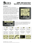
™ ® 750 Control Panel Operation and Troubleshooting Introduction The CANplus® 750 (CP750™) control panel is a universal platform to monitor, control and automatically start/stop both electronically and mechanically governed diesel engines. The microprocessor-based, solid-state design uses high power semiconductors instead of outdated electromechanical relays to ensure reliable high current switching. Graphical gauge pages or a single large analog gauge are displayed on the 4.25” diagonal LCD. Virtually any SAE J1939 parameter reported by the ECU (Engine Control Unit) can be displayed including RPM, coolant temperature, oil pressure, engine hours, voltage and diagnostic codes. An analog fuel level input broadcasts the fuel level across the CANbus to the display and other J1939 devices. The trans-reflective, backlit display is clearly readable in both bright sunlight as well as total darkness and is housed in a rugged IP67 rated housing. Current alarm conditions are displayed in plain language on popup messages and can be viewed in the alarm list. Various diagnostic screens allow detailed investigation of the CANbus data stream. By accessing the Configuration Menu, users can customize displayed data to show metric or US units, display language and various other parameters such as the full-scale reading of gauges. Four bright LEDs below the display indicate Auto Standby, Preheat, Stop and Warning status. Five buttons access a context dependent button bar when any button from 1 to 4 is pressed. The graphical menu structure uses easily understood icons to indicate the button’s current function. After 5 seconds of inactivity the button bar disappears. Button 1 Button 2 Button 3 Button 4 Button 5 Analog Gauge Pages Digital Gauge Pages Single Analog Gauge Active Alarm Page Gauge Adjust Repeated presses cycle through four pages of analog gauges (16 total). Repeated presses cycle through four pages of digital gauges (16 total). Repeated presses cycle through available analog gauges. Displays active alarms including a plain language description. Configures the parameters displayed by gauge pages. 463-3000-08 Initial - 18-Feb-2008 CANplus and CANplus logo are registered trademarks of LOFA Industries, Inc. CP750 and the LOFA logo are trademarks of LOFA Industries, Inc. 1 ® 750 Control Panel Operation and Troubleshooting Note Most problems with electronically controlled engines can be pinpointed via ECU diagnostic messages. Use the display or ECU diagnostic tool to view fault codes. Engine state information and diagnostic codes displayed by the CANplus display are provided via the CANbus. Automatic Operation The CP750 panel features advanced Automatic Start/Stop control which can meet almost any requirement. Two switch inputs and a transducer input support a number of control scenarios. Single switch mode allows reliable operation with a single switch. Dual switch operation allows greater hysteresis when needed. The transducer input supports simple start/stop operation by level or pressure and maintenance modes with speed modification. Programmable high and low set points control start/stop operation. Level maintenance modes monitor the operating point and adjust the engine speed to match the targeted set point with configurable aggressiveness. Dual switch inputs can be combined with the transducer input for redundant safety to protect against transducer sensor clog or failure. Throttle Control The standard Ramp Throttle uses a momentary rocker switch to adjust the integral throttle control. All throttle commands are sent directly to the engine using CANbus throttle control. Note Throttle control requires CANbus throttling to be enabled in the ECU. CANbus throttling is also known as Torque Speed Control or TSC1. Other throttle options include Digital Rotary Throttle, Two-State Throttle (Idle/Run) or Three-State Throttle (Idle/Intermediate/Run). The Digital Rotary can be installed with the Throttle Ramp Throttle or Three-State Throttle to adjust the Idle, Intermediate and Run speeds. Service Timers The CP750 display provides sixteen (16) service timers to alert the operator of needed maintenance. The time interval for each timer can be adjusted in 10 hour increments. A popup message is displayed after the display self test if a timer has expired alerting the user that service is required. The message is displayed on each power up until the elapsed timer is disabled or reset. CANplus Messenger Telemetry Option The optional CANplus Messenger system provides a variety of features to protect and support the equipment investment. Remote monitoring can alert maintenance requirements, operational problems, improper operation and location with geo-fence alert. The Web-browser interface allows monitoring an entire fleet of equipment in a central location. Contact LOFA Industries for more information. 2 463-3000-08 Initial - 18-Feb-2008 ® 750 Control Panel Operation and Troubleshooting Mechanically Governed Engines On mechanically governed engines, the CANplus I/O Board performs the ECU function by monitoring low oil pressure, high temperature and two additional engine faults. Three analog inputs broadcast the oil pressure, engine temperature and fuel level across the CANbus to the display and other J1939 devices. The engine speed can be controlled using a mechanical throttle or by using the standard CP750 throttle controls with the optional CANplus Actuator Kit. Automatic throttling with automatic start/stop requires the use of the CANplus Actuator Kit. Only single speed operation is possible with a mechanical throttle. Warning! When replacement parts are required, LOFA Industries recommends using replacement parts supplied by LOFA or parts with equivalent specifications. Failure to heed this warning could lead to premature failure, product damage, personal injury or death. Automatic Start/Stop Warning! When the key is turned to the autostart position and a start condition exists, the panel will start immediately! Always configure parameters by turning the key to run. Do not configure the panel in the autostart position! Always use lock out/tag out procedures when servicing autostart equipment! Important Safety Information The warnings in this publication are not all inclusive. LOFA Industries cannot anticipate every potential hazard. Appropriate safety rules and precautions should be followed with any tool, work method or operating procedure. Improper procedures, tools and materials may cause damage or make the equipment unsafe to operate. Only persons with appropriate training, skills and tools should perform these functions. Improper operation, maintenance or repair of this product can be dangerous and may result in injury or death. Do not operate or perform any maintenance or repair on this product until all operation, maintenance and repair information is read and understood. The information, specifications and illustrations in this publication are based on information available at the time of publication. All items are subject to change at any time without notice. 463-3000-08 Initial - 18-Feb-2008 3 ® 750 Control Panel Operation and Troubleshooting Manual Operation Turning the control system key to the run position energizes the ECU, all LEDs illuminate once and a start-up screen is displayed while a self test is performed. If the display beeps for longer than 1 second, it indicates a self test fault. Users can attempt to rectify the fault by restoring factory defaults (see Configuration Menu for details). Contact LOFA Industries for assistance if the fault persists. After the start-up screen is cleared, the display shows readings on its virtual gauges. Initially the analog gauges are displayed but the display uses the last displayed screen on subsequent startups (see Preferred Screen Store for details). If the ECU is preheating when the key switch is turned to the run position, the Preheat LED is illuminated. Preheat time varies with atmospheric and engine conditions. After waiting for the Preheat LED to extinguish, the engine is cranked by turning and holding the key switch in the start position until the engine starts. Note The ECU will not preheat unless conditions warrant. If necessary, starting the engine may be attempted by turning the key to the start position without waiting for preheat to expire. The key switch is spring loaded to return automatically to the run position when released. The key switch includes an interlock to prevent the key from being turned to the start position while the engine is running. The key switch must be turned to the off position to reset the starter interlock before the switch can be turned to the start position again. Throttle Control The type of throttle operators installed along with the configured values of Minimum Requested RPM, Idle RPM, Intermediate RPM, Run RPM and Maximum Requested RPM determine throttle operation. The engine speed can be adjusted above Run RPM and below Idle RPM but the requests can not fall below Minimum Requested RPM or above Maximum Requested RPM. The ECU determines how the engine responds to the throttle requests and will not allow the engine speed to fall below the ECU minimum or maximum RPM. Note The Minimum Requested RPM and Maximum Requested RPM can only be configured using the CANplus Configurator. See Configuration below for more information. Ramp Throttle The standard Ramp Throttle uses a momentary rocker switch to adjust the requested engine speed. When first started the requested engine speed is Idle RPM. Pressing and releasing the rabbit icon increases the speed requested by 25 RPM. Pressing and holding the rabbit icon causes the speed to accelerate to full speed in a few seconds. Similarly, pressing the turtle icon decreases the requested speed. 4 463-3000-08 Initial - 18-Feb-2008 ® 750 Control Panel Operation and Troubleshooting Two-State Throttle The optional Two-State Throttle uses a two position rocker switch to adjust the requested engine speed. Pressing the rabbit icon requests the engine to go to Run RPM. Pressing the turtle icon requests the engine to go to Idle RPM. Three-State Throttle The optional Three-State Throttle uses a three position rocker switch to adjust the requested engine speed. Pressing the rabbit icon requests the engine to go to Run RPM. The intermediate position requests the engine to go to Intermediate RPM. Pressing the turtle icon requests the engine to go to Idle RPM. Digital Rotary Throttle The optional Digital Rotary Throttle uses a rotary switch to simulate the operation of a throttle potentiometer. Like the Ramp Throttle, when first started the requested engine speed is Idle RPM. Turning the throttle knob clockwise increases the requested engine speed. Turning the throttle knob counter-clockwise decreases the requested engine speed. Note When used in combination with the Three-State Throttle, the Rotary Throttle can only be used to make speed adjustments when the switch is in the intermediate position. The Rotary Throttle can be used to reprogram the Idle, Intermediate and Run RPMs when used in combination with the Ramp Throttle or Three-State Throttle. After adjusting the engine to the desired speed with the throttle knob, press and hold the knob and then press and hold the throttle switch position to be changed. After two seconds all LEDs will flash indicating the current speed has been stored. The knob and switch can now be released. Automatic Start/Stop Operation Turning the control system key to the Autostart position causes all LEDs illuminate once, the Auto Standby indicator is illuminated and the start-up screen is displayed while a self test is performed. After the start-up screen is cleared, the display shows the transducer reading and switch status on the Transducer/Switch gauge. All other CANbus values will show since the ECU is not energized at this time. After one minute the display is powered down to reduce battery drain. The automatic start/stop system is still functioning as indicated by the Auto Standby LED. Start Event 463-3000-08 Initial - 18-Feb-2008 At Run Speed Intermediate seconds Run Intermediate When the configured stop conditions exist, the panel reduces the engine speed per the throttle profile and stops the engine. If the configured start conditions exist before the shutdown process is complete the engine Stop Event RPM Once the configured automatic start condition exists, the display powers up, the panel starts the engine and follows the throttle control profile configured (see diagram). The flexible throttle profile includes various speeds and times for a variety of scenarios. Cool Down minutes Warm Up seconds Idle Ramp to Run seconds Ramp Up seconds Ramp Down seconds Time Engine Running Engine Stop 5 ® 750 Control Panel Operation and Troubleshooting will return to the previous speed until the stop condition exists. Automatic Start/Stop Warning! When the key is turned to the autostart position and a start condition exists, the panel will start immediately! Always configure parameters by turning the key to run. Do not configure the panel in the autostart position! Always use lock out/tag out procedures when servicing autostart equipment! Start and Stop Events The Start and Stop Events are determined by the combination of Start/Stop Mode and Function. See the table below for Start/Stop Modes Sngl Switch Switch one controls automatic operation. Dual Switch Both switch inputs control automatic operation. Transducer The transducer input controls automatic operation. Xducer & Sw The transducer input controls automatic operation with dual switch mode as the backup. The switch inputs override the transducer if actuated when the transducer is not calling for an automatic cycle. Start/Stop Functions Empty Uses the selected mode to reduce the level or pressure. Fill Uses the selected mode to increase the level or pressure. Maintain Out Uses the transducer to maintain the level or pressure at or below the target. Maintain In Uses the transducer to maintain the level or pressure at or above the target. Mode▼ Sngl Switch Dual Switch Transducer Xducer & Sw Function ► Start Empty SW1 Close Fill SW1 Open Stop SW1 Open SW1 Close Start SW1 and SW2 Close SW1 and SW2 Open Stop SW1 and SW2 Open SW1 and SW2 Close Start Stop Start Above High Set Point Below Low Set Point Above High Set Point or SW1 and SW2 Close Below Low Set Point or SW1 and SW2 Open Below Low Set Point Above High Set Point Below Low Set Point or SW1 and SW2 Open Above High Set Point or SW1 and SW2 Close Stop Maintain Out Maintain In Above High Set Point Below Low Set Point Above High Set Point or SW1 and SW2 Close Above High Set Point or SW1 and SW2 Close Below Low Set Point Above High Set Point Below Low Set Point or SW1 and SW2 Open Below Low Set Point or SW1 and SW2 Open Note When the switch inputs are the source of the start event in Xducer & Sw mode, only the switches will stop the engine. 6 463-3000-08 Initial - 18-Feb-2008 ® 750 Control Panel Operation and Troubleshooting Maintain Functions The Maintain In and Maintain Out functions adjust the engine speed to keep the transducer level at the Target Set Point. The Servo Gain adjusts how aggressively the throttle is adjusted while the Servo Delay controls how often the throttle is adjusted. Note Maintain functions are only available in the Transducer or Xducer & Sw modes. The direction of the throttle adjustment is dependent on the selected mode as shown in the table. Transducer State Above Target Below Target Maintain Out Increase Speed Decrease Speed Maintain In Decrease Speed Increase Speed In some situations the transducer level may fluctuate around the Target Set Point such as the water level on a windy day. To limit throttle hunting using the maintain functions a dead band can be programmed. This value prevents throttle adjustment while the level is within the band (see diagram). In essence the speed is considered to be at the target whenever it is within the dead band. Note The dead band entered is amount above and below the target point. For example, if the target is 5.0 feet with a 0.1 foot dead band, the dead band is 4.9 to 5.1 feet. 463-3000-08 Initial - 18-Feb-2008 Level o r Pressure Dead Band High Set Point Target Set Point Dead Band Low Set Point 7 ® 750 Control Panel Operation and Troubleshooting CANplus Display Soft buttons simplify the user interface by displaying a button bar above the buttons when any of the first 4 buttons (buttons 1 to 4, starting from the left) are pressed. Icons on the button bar change to represent the current function of each button. The button bar disappears after 5 seconds if no further buttons are pressed. Note Different software versions may have slightly different displays. Analog Gauge Pages Analog Gauge Pages provide four independent pages of analog gauges. To enable Analog Gauge Pages, press any of the first 4 buttons to show the top level button bar and then press button 1 . Alternate pages are selected by repeated pressing of button 1. The four standard gauge pages are shown below. Page 1 Page 2 Page 3 Page 4 Note Engine Hours are displayed as a digital value even on Analog Gauge Pages. The default gauge pages represent 13 selections since the tachometer is repeated in the upper left quadrant of each page. All 16 gauges may be configured by the user to create an application-specific view of CANbus data. Gauges on the current page can be changed via Adjust Mode, accessed by pressing button 5 when the button bar is visible. Gauges can be changed on any of the four pages by selecting the page to be changed and then entering Adjust Mode. In Adjust Mode a new button bar is displayed identifying the button functions. Button 1 corresponds to the upper left gauge, button 2 to the upper right gauge, button 3 to the bottom left gauge and button 4 to the bottom right gauge. Successive presses of the buttons selects a different parameter for the gauge. Adjust Mode is exited by pressing button 5 and storing the new configuration even when power is removed. Note A gauge selection can only appear once per page. To move a gauge selection, the existing gauge location must be changed first. Gauge selections are limited to the data currently being received. Gauge pages can be configured in Demo mode to select any supported parameter. See Data Parameters Monitored for a complete list of available parameters. 8 463-3000-08 Initial - 18-Feb-2008 ® 750 Control Panel Operation and Troubleshooting Adjust Mode can be disabled in the Configuration Menu to prevent accidental changes. Digital Gauge Pages Digital Gauge Pages display the same data as the Analog Gauge Pages but in digital only format. To enable Digital Gauge Pages, press any of the first 4 buttons to show the top level button bar and then press button 2 . Alternate pages are selected by repeated pressing of button 2. The four standard gauge pages are shown below. Page 1 Page 2 Page 3 Page 4 Note The 16 gauges are the same for Analog and Digital Gauge Pages. Adjustments in either Analog Gauge Pages or Digital Gauge Pages affect the same gauge in the other mode. Single Analog Gauge Single Analog Gauge uses the entire display for a single large analog gauge. This mode is enabled by pressing any of the first 4 buttons to show the top level button bar and then press button 3 . The gauge displayed is selectable by repeatedly pressing button 3 while in the Single Analog Gauge mode while the menu bar is visible. The currently displayed gauge is stored when power is removed (see Preferred Screen Store). Note Gauge selections are limited to the data currently being received. See Data Parameters Monitored for a complete list of available parameters. Analog Transducer/Switch Gauge The Analog Transducer/Switch Gauge displays the transducer value and the switch input states. The left column represents the values as a bar graph with a digital value displayed below. The right column shows whether the switches are ‘open’ represented by the pointer being down or ‘closed’ represented by the pointer being up. Digital Transducer Gauge The Digital Transducer Gauge displays the transducer value as a digital only value. The switch state is not displayed on the Digital Transducer Gauge. Active Alarms A flashing popup window is overlaid on the current screen when an active alarm is received. The popup includes a plain language description in addition to the standard SPN/FMI (Suspect Parameter 463-3000-08 Initial - 18-Feb-2008 9 ® 750 Control Panel Operation and Troubleshooting Number/Failure Mode Indicator) pair defined by the SAE J1939 standard. Additionally, if enabled, the beeper sounds as an audible cue. Example alarm message, alarm list screens showing unacknowledged conditions and acknowledged alarms. After acknowledgement, the exit button becomes active. Note Standard J1939 abbreviations are used for alarms. MS = Most Severe, MOD= Moderately Severe, LS = Least Severe. Alarm List The Alarm List is accessed by pressing any button while an alarm popup is displayed or by pressing any of the first 4 buttons to show the button bar and then button 4 . Alarms not yet acknowledged are shown in grey on black while acknowledged alarms are shown in black on grey. The list also indicates when the alarm occurred if engine hours are available. The most recent alarm is displayed at the top of the list. The list can be scrolled using buttons 1 and 2 and alarms acknowledged by pressing button 3 . The Alarm List can be closed by pressing Button 5 once the alarms are acknowledged. An alarm indicator is displayed near the upper right corner of the display as long as alarms are active. The indicator and alarm messages in the list are automatically removed when the alarm is no longer received for a few seconds. Note Only active faults are displayed in the alarm list. Once a fault is corrected it is automatically removed from the list. To view previously active faults use the engine diagnostic tool. 10 463-3000-08 Initial - 18-Feb-2008 ® 750 Control Panel Operation and Troubleshooting Configuration To adapt the CP750 panel to the requirements of a particular application, a large number of parameters are configurable. The most commonly modified parameters can be accessed by invoking the Configuration Menu of the display. Infrequently changed parameters and those parameters that typically need to be restricted such as Maximum RPM are accessible only through the CANplus Configurator. The CANplus Configurator is a Windows® PC program and a hardware adapter that allows total access to the parameters of the panel. For more information about the CANplus Configurator, please contact LOFA. Configuration Menu This Configuration Menu allows the user to set various operating parameters such as US or metric units, scale limits for tachometer and service timers. The configuration menu is entered by pressing and holding button 5 (the right hand button) in any mode for at least 3 seconds. If PIN (Personal Identification Number or ‘password’) entry is enabled the correct PIN must be entered to access the configuration menu. The top level configuration menu is displayed as shown. Buttons 1 and 2 allow you to choose from Display, System, Autostart, Settings, Telemetry or Db Viewer. Pressing button 4 selects the chosen menu item indicated by bold text and the selection arrow . Each item is described in detail on the following pages. Settings are automatically stored when exiting the current menu even when power is removed. The Configuration menu and its six choices. Pressing Button 4 selects the highlighted menu item. Button 5 exits the configuration mode. Note Most configuration changes take affect immediately. Some such as Idle RPM take affect on the next power up. 463-3000-08 Initial - 18-Feb-2008 11 ® 750 Control Panel Operation and Troubleshooting Display Menu The Display Menu allows the user to configure items affecting how information is displayed. Units Menu This menu allows the user to set the units used for speed, distance, pressure, volume and temperature independently. Button 4 cycles through the available values for the selected item. Speed MPH (miles per hour) km/h (kilometers per hour) Knts (knots) Distance Miles km (kilometers) NM (nautical miles) Pressure PSI (pounds per square inch) bar (barometric units) kPa (kilopascals) Volume Gal (US gallons) IGal (Imperial gallons) Liters Language Menu This menu allows the user to choose between English, Swedish, French, German, Spanish, Italian, Dutch and Portuguese. The currently selected value is indicated by the check mark Button 4 selects the highlighted value. . Button Beep The soft buttons emit an audible beep when this item is On. Button beep is disabled by setting this item to Off. The audible beep still sounds when an alarm occurs. Button 4 cycles between On and Off. Temperature °F (Fahrenheit) °C (Celsius). 12 463-3000-08 Initial - 18-Feb-2008 ® 750 Control Panel Operation and Troubleshooting Gauges Menu This menu allows the user to configure aspects of the gauges displayed. Button 3 selects the previous value while Button 4 selects the next value of the highlighted item. Max RPM Sets the full scale RPM indicated by the tachometer gauge. RPM Service Sets the sixteen (16) service intervals in hours and resets the service timer. Setting the service interval to 0 disables the timer and the word Off is displayed. Pressing Button 4 allows adjusting the selected service timer. 2500, 3000, 3500, 4000, 4500, 5000, 6000, 7000, 8000 or 9000 Max Speed Sets the full scale speed indicated by the speedometer gauge. MPH 15, 20, 25, 30, 35, 40, 45, 50, 55, 60, 70, 75, 80, 85, 95 or 100 km/h 20, 30, 40, 50, 60, 70, 80, 90, 100, 110, 120, 130, 140, 150 or 160 Quad Adjust Allows the user to disable Adjust Mode of the Analog and Digital Gauge Pages. Button 3 disables while Button 4 enables Quad Adjust. Disabling Adjust Mode locks the current gauge configuration and prevents the operator from accidentally changing the gauge configuration. 463-3000-08 Initial - 18-Feb-2008 Button 1 decreases the service interval time while Button 2 increases the service interval time in 10 hour increments. Holding Button 3 for approximately 3 seconds resets Next Service In to the current service interval. The service timer descriptions can be changed using the CANplus Configurator. Note It is not possible to set the service timers if engine hours are not being received by the display. 13 ® 750 Control Panel Operation and Troubleshooting System Menu The System Menu allows the user to configure items affecting how the system functions. . Button 4 through the available values for the selected item. Demo The display supports several demo modes to operate with simulated data. Mode 1 simulates speed data and engine parameters. Mode 2 only simulates engine parameters. Mode 3 simulates speed data, engine parameters and alarms. Mode 0 disables Demo Mode. Demo is automatically set to 0 (Off) if live data is received. Restore Defaults This allows resetting all configuration information to default US or Metric units. Additionally the display is reset to the initial configuration. 14 cycles The default settings are: Setting US Metric Language English Button Beep On Service Timers Off Display Mode Analog Gauges Gauge Pages Defaults Quad Adjust On Demo Mode 0 (Off) Engine Source 0 Display CAN Address 40 Alarm Filter Glb SPN Version 1 Speed Source Auto PIN Entry Off PIN 1111 Max Gauge RPM 2500 Max Gauge Speed 40 MPH 60 km/h Speed Units MPH km/h Distance Units Miles km Pressure Units PSI kPa Volume Units Gal l Temperature Units ºF ºC 463-3000-08 Initial - 18-Feb-2008 ® 750 Control Panel Operation and Troubleshooting Com Viewer J1939 Settings Displays CANbus data received and engine configuration transmitted by the ECU. This screen allows adjustments specific to the J1939 data link. J1939 Viewer Engine Source This screen provides a hexadecimal dump of the messages received on the CANbus. This viewer displays the raw data. To see the decoded data use the Db Viewer. Selects which source the display listens to for gauge data. Every device on a J1939 network has a unique address (in the range 0-254) to which the display can choose to listen. The display listens to a single data source; usually the ECU at address 0. Note Incorrectly configuring the Engine Source address will result in no data available for display. Button 1 freezes the display while button 2 shows CANbus data statistics screen. Display CAN Add As mentioned previously, every device has a unique address and the display is no different. The default display address is 40, the recommended address for single engine setups. Note Incorrectly configuring the Display Address can result in data collisions on the CANbus. Engine Config Alarm Filter This screen displays the engine configuration information received from the ECU. This setting specifies whether the display will display alarms from all sources (Glb or global) or only the source address specified in the Engine Source setting (Src or source). SPN Version Button 2 selects the next page of engine configuration while button 1 selects the previous page. 463-3000-08 Initial - 18-Feb-2008 Selects the default SPN (Suspect Parameter Number) conversion method version to 1, 2 or 3. Version 4 is automatically detected, but older engines that use conversion method 1, 2 or 3 requires setting this parameter correctly. 15 ® 750 Control Panel Operation and Troubleshooting Note Consult your engine supplier to establish the appropriate SPN conversion method version. Selecting the wrong version will cause alarm data to be displayed incorrectly. Speed Source There are 3 sources of speed data the display can decode. The settings for this parameter are AUTO, NMEA, WHEEL, NAV and OFF. AUTO prioritizes the sources (highest to lowest); NMEA, WHEEL (PGN 65265), NAV (PGN 65272). The selection can be forced to one of the available sources by selecting it explicitly. Selecting OFF stops the display listening to any source of speed data. Button 1 adjusts the first digit of the PIN. Button 2 adjusts the second digit, button 3 the third digit and button 4 the fourth digit. The PIN is entered using button 5 . PIN Change This allows changing the PIN. The user is prompted for the current PIN The user is prompted for the new PIN. PIN Settings By default PIN security is disabled. The user is prompted to enter a PIN every time the Configuration Menu is accessed after this feature is enabled. The new PIN must be confirmed before the PIN is changed. PIN Entry This allows turning PIN Entry On or Off. To enable the PIN entry feature select PIN Settings and press button 4 to enable. The current pin must be entered (default is 1111) as a security feature. Once the PIN has been entered the feature is enabled. PIN Entry is disabled by setting PIN Entry to Off. If the new PINs match a confirmation screen is displayed. The digits of the PIN are entered by using the buttons corresponding to the digits of the PIN. 16 463-3000-08 Initial - 18-Feb-2008 ® 750 Control Panel Operation and Troubleshooting If the two PINs entered do not match an error message is displayed and the PIN is unchanged. About Displays the following product information: Warning If the PIN is changed from the default and the new PIN is lost, the configuration mode will not be accessible. Clearing the PIN requires returning the display to LOFA for service. ID/Build EEPROM PART No VERS CHK SOURCE LIB1 LIB2 Serial number of the display Number of writes on EEPROM Unit part number Software version number Flash memory checksum The source of received data Low level system library version Low level Graphical Display Interface library version (if used) Note This screen can not be exited until the checksum calculation is complete. Checksum calculation takes approximately 10 seconds and is complete when the checksum value changes from Calculating… to a hexadecimal value such as 0x704E – OK 463-3000-08 Initial - 18-Feb-2008 17 ® 750 Control Panel Operation and Troubleshooting Autostart Menu This submenu allows the user to configure automatic start/stop operation. Refer to Automatic Start/Stop Operation for more information. Mode This menu selects the basic automatic start/stop operation mode. Button 4 cycles between Single Switch, Dual Switch, Transducer or Xducer & Sw. Function This menu selects the automatic start/stop function. Button 4 cycles between Empty, Fill, Maintain Out and Maintain In. Throttling Menu The throttling menu allows the user to configure throttle control. Idle RPM Selects the RPM the control system will request for idle speed. Idle can be set to compensate for parasitic loads such as hydraulic pumps or compressors. Idle RPM is the low speed setting of the optional two state or three state throttle switches. Note The minimum engine speed is set by the ECU. Requesting a lower speed causes the engine to run at the ECU minimum speed. RPM limits are programmed into the panel to limit the requested speed. Changing the panel Minimum Requested RPM and Maximum Requested RPM requires using the CANplus Configurator. The throttling menu allows programming the automatic start/stop throttle profiles as shown in the following diagram. 18 463-3000-08 Initial - 18-Feb-2008 ® 750 Control Panel Operation and Troubleshooting Intermediate RPM Selects the RPM the control system will request for intermediate speed. The intermediate speed can be used to prime pump or charge lines during automatic start/stop operation. Intermediate RPM is also the middle setting of optional three state throttle switches. Note Setting the Intermediate RPM to the same speed as Idle RPM and Ramp to Run to 0 seconds is effectively two speed automatic operation. Run RPM Selects the RPM the control system will request for run speed. The run speed is the normal operating speed during automatic start/stop operation. Run RPM is the high speed setting of the optional two state or three state throttle switches. Ramp to Run s Selects the number of seconds to ramp from intermediate speed to run speed after intermediate warm-up Ramp Down s Selects the number of seconds to ramp from current speed to idle speed. The ramp down time begins when the automatic start/stop system detects a stop event. Cool Down m Selects the number of minutes to operate at idle speed after ramp down time. At the end of the cool down period the engine will be stopped. Servo Configures the servo profile for autostart maintain modes Ramp Up/Down This submenu configures the speed profile for automatic start/stop operation. Gain Controls the aggressiveness of the maintain servo modes. Warm Up s Selects the number of seconds to operate at idle speed before beginning the ramp to intermediate speed. The warm up time begins when the starter is disengaged. Delay 10mS Controls how quickly the maintain servo mode responds to changes in level. Transducer This submenu configures the transducer type and set points. Ramp Up s Selects the number of seconds to ramp from idle speed to intermediate speed after warm-up Intermediate s Selects the number of seconds to operate at intermediate speed before ramping to run speed Type Selects between Level and Pressure 463-3000-08 Initial - 18-Feb-2008 19 ® 750 Control Panel Operation and Troubleshooting Range Starter Selects appropriate range for the transducer type This submenu configures starter control options for autostart High Set Point For Empty and Maintain Out modes, sets the level that begins an autostart cycle. For Fill and Maintain In modes sets the level that ends the cycle. Maintain Point Sets the target point for maintain modes Low Set Point Restart Attempts For Empty and Maintain Out modes sets the level that ends an autostart cycle. For Fill and Maintain In modes sets the level that begins a cycle. Restart Delay Sec Selects the number of times to attempt restart Dead Band Selects the number of seconds to wait before attempting a restart Sets the amount of change from the target point required to alter the engine speed. Start on Sec 20 Selects the maximum number of seconds the starter can be engaged 463-3000-08 Initial - 18-Feb-2008 ® 750 Control Panel Operation and Troubleshooting Settings Menu This submenu allows the user to configure CANplus hardware. Warning Governor Selects between Elect (electronically governed) and Mech (mechanically governed) engines modes. For mechanically governed engines the CANplus I/O Board functions as an ECU, broadcasting engine parameters such as oil pressure and temperature on the CANbus. Note Switching governor modes requires cycling power before calibrating the RPM. The CANplus Configurator must be used to configure mechanical engine parameters. Incorrectly configuring the CP750 CAN Address prevents the display from receiving I/O Board data for the display menus and can result in data collisions on the CANbus. Calibrate RPM Calibrates the tachometer input for mechanically governed engines to allow the CANplus I/O board to measure the engine speed. This signal may be provided by an alternator frequency tap, proximity switch. An optional amplifier/divider can be added for use with a magnetic pickup. CP750 CAN Add Selects the address used by the display to communicate with the CANplus I/O board. The default I/O Board address is 128. Note Engine data is always transmitted using address 0 in mechanically governed mode. Note Calibrate RPM is only available on mechanically governed engines. The RPM must be calibrated for automatic start/stop operation to function. 463-3000-08 Initial - 18-Feb-2008 21 ® 750 Control Panel Operation and Troubleshooting Crank the engine and measure the engine RPM with a handheld tachometer. Select Calibrate RPM and enter the digits of the measured RPM using the buttons corresponding to the digits of the RPM. Button 1 adjusts the first digit of the RPM. Button 2 adjusts the second digit, button 3 the third digit and button 4 the fourth digit. The RPM is entered using button 5 . Alarm Settings Configures the set points for the transducer alarm messages. The alarm is transmitted as SPN 1083 with FMI 1 for a low alarm and FMI 0 for a high alarm. When the calibration is complete the LEDs will begin a blinking sequence. The power must be cycled to continue configuration or operation. Aux Output Selects the Aux Output function and provides a 1 amp low side switch. Running The output is active when the engine RPM exceeds 500 RPM Low Level Sets the transducer low level alarm set point. High Level Sets the transducer high level alarm set point AS Armed The output is active when the keyswitch is in the Autostart position and the engine has not stopped due to a fault At Speed The output is active when the engine is at or above the Operating RPM Prestart The output is prestart alarm activated 10 seconds before the engine automatically starts Note The Aux Output is available on a connector in the I/O Board only. Changing the prestart alarm time requires using the LOFA Configurator. 22 463-3000-08 Initial - 18-Feb-2008 ® 750 Control Panel Operation and Troubleshooting Telemetry Menu This menu allows configuring the optional telemetry system. Telem J1939 Address Defines address the telemetry module is using for CANbus communications. Status Displays telemetry and modem status information retrieved from the telemetry module: Note The display will be unable to communicate with the telemetry module if this address is incorrect. Modbus Address Selects the Modbus slave address the telemetry module will use for Modbus communications. 463-3000-08 Initial - 18-Feb-2008 Modem Type Cell Reg Cell State Identifies the modem type Identifies cell modem registration Indicates cell state and signal strength GPS Indicates GPS status RTC Indicates number of days since real time clock cellular update Modbus SSLT Indicates Modbus slave status Hdw Status Indicates various hardware status items Software Ver Indicates the version of software in the Messenger 23 ® 750 Control Panel Operation and Troubleshooting Db Viewer The Database Viewer displays and decodes all data monitored by the display. This diagnostic tool allows viewing data not normally displayed. The list can be scrolled using buttons 1 and 2 and closed by pressing Button 5 . Note The Database Viewer is always in English regardless of language selected. Preferred Screen Store The display automatically stores the current screen as the preferred screen after a delay of approximately 15 seconds. The display will use the last stored screen on the next power-up. Note Selecting Restore Defaults restores the Analog Gauge Pages and default gauges. Popup Messages and Alerts Service Required Users can set up to sixteen service timers in hours in the Configuration menu. The Service Required popup is displayed at power up when one or more service timers has expired. Pressing any button removes the popup. If no button is pressed the popup closes in approximately 5 seconds. Pop-up warnings of service required and data communications failure. 24 463-3000-08 Initial - 18-Feb-2008 ® 750 Control Panel Operation and Troubleshooting Data Communications Failure The data communications failure popup icon flashes if the display does not detect data. The warning disappears and normal operation resumes once data is detected. Note Incorrectly configuring the Engine Source address will result in no data available for display. Data Not Available Gauges and the Db Viewer will display normal when parameter data is received. if the desired data is not available. The display value returns to Note In Autostart Standby only the transducer gauge displays data since the ECU is not powered. Adjusting Lighting and Contrast Pressing button 5 (the right-hand button) when there is no menu bar opens the lighting and contrast menu bar. The display has a number of back-lighting levels allowing the display to be read in the dark. The level is adjusted by pressing buttons 1 (decrease) or button 2 to (increase) illumination. Contrast is adjusted in the same manner using buttons 3 and 4 . Note The display adjusts the contrast with ambient temperature. Manual contrast adjustments are only necessary with extreme climate change. The menu is exited by pressing button 5 powered off. . The lighting and contrast settings are retained after the unit is Note If the contrast has been adjusted poorly, the factory setting is restored by pressing buttons 1 thru 4 simultaneously. This action does not change other user-configured settings. 463-3000-08 Initial - 18-Feb-2008 25 ® 750 Control Panel Operation and Troubleshooting Indicators Auto Standby LED (Green) A solidly illuminated Auto Standby LED indicates the keyswitch is in the auto start position and the system is ready to start. Preheat LED (Amber) A solidly illuminated Preheat LED indicates the engine is preheating. When the LED extinguishes, the preheat period is complete and the engine may be cranked. Note The CANplus only reports when the ECU is requesting preheat. Cold starting aids may not be installed in all engine configurations. Engine Stop LED (Red) A solidly illuminated Engine Stop LED indicates the ECU has stopped the engine due to a fault. Note ECU programming determines the response to warnings and failures. Typically the ECU can be programmed to shutdown, derate or run to failure. The CANplus only displays ECU reported conditions. Warning LED (Amber) A solidly illuminated Warning LED indicates a warning reported by the ECU. Note The Warning LED is not used in Mechanical Governor mode. Gauges Analog gauges can be added by removing blind covers and installing the gauge. No wiring or interface is provided in standard control systems. 26 463-3000-08 Initial - 18-Feb-2008 ® 750 Control Panel Operation and Troubleshooting Typical J1939 Wiring Topology Most electronically governed engine installations include a harness with built in J1939 backbone. Use twisted shielded pair with a drain wire for CANbus wiring terminated with 120Ωresistors at each end. The maximum length for the bus is 131 feet (40 m) and stubs should not exceed 39 inches (1m) in length. 463-3000-08 Initial - 18-Feb-2008 27 ® 750 Control Panel Operation and Troubleshooting Harness Sealed Connectors The provided Deutsch sealed weather-proof plug includes a locking ring device which must be turned counter clockwise to separate the connectors. To positively seat the connectors the locking ring is turned clockwise. Warning LOFA does not recommend using dielectric grease or sealant with sealed connectors. These chemicals may cause seal damage and allow water entry. Use LOFA provided cavity plugs to seal the connector if wires are removed. Unsealed Connectors For unsealed connectors exposed to the elements, LOFA recommends using dielectric grease to protect contacts. Warning LOFA does not recommend using sealant with unsealed connectors. Sealant traps moisture in the connector and encourages corrosion. Harness Routing The minimum routing radius of the wiring harnesses should be at least two times the diameter of the wiring harness. Bends should be avoided within 1 inch (25 mm) of any connector in order to avoid seal distortion allowing moisture to enter the connector. 28 463-3000-08 Initial - 18-Feb-2008 ® 750 Control Panel Operation and Troubleshooting Battery Circuit Requirements Warning Improper wiring can cause electrical noise, unreliable operation and may damage the control system or other components. All power connections must be free from foreign materials, including paint, which may interfere with proper connection. A reliable dedicated power circuit must be provided for the control system. LOFA recommends the power connection be made directly to the battery. Grounding through frame members is not recommended! All circuit paths must be capable of carrying any likely fault currents without damage. Do not reverse the battery polarity. Attempting to crank the engine when the polarity of the battery connections is reversed may damage the control system. Battery Positive Connection The electronic control system operates on either a 12 VDC or 24 VDC electrical systems. The unswitched battery positive connection to the control system is made at the weather proof connector. The control system provides switched positive battery protected by solid-state MOSFETs. These outputs include integral protection against overloads and short circuits. An integral 40 AMP slow blow fuse protects the unswitched battery positive circuit. Powering the control system through dedicated circuits reduces the possibility of system damage. Warning Disconnecting the battery while the engine is running may damage electrical components. When using a battery disconnect switch, LOFA recommends using a 2 pole switch to disconnect both the battery and alternator output. Note A maximum of three ring terminals should be connected to a power stud in order to ensure integrity of the connection. The use of more than three terminals can cause the connection to become loose. Voltage Drop If control system voltage drops below 6 volts for more than one tenth of a second, the control system may reset causing the self test to reactivate. Resetting the control system is equivalent to quickly turning the key switch to off and back to run without starting the engine. Voltage drops can be caused by a discharged battery, transients from external equipment, improper wire sizes, faulty wiring or nearby lightning strikes. 463-3000-08 Initial - 18-Feb-2008 29 ® 750 Control Panel Operation and Troubleshooting Suppression of Voltage Transients (Spikes) Warning The installation of voltage transient suppression at the transient source is required. LOFA follows SAE recommended electrical environment practices. Inductive devices such as relays, solenoids and motors generate voltage transients and noise in electrical circuits. Unsuppressed voltage transients can exceed SAE specifications and damage electronic controls. I Relays and solenoids with built-in voltage transient suppression diodes are recommended whenever possible. Refer to the illustration for proper installation of diodes when built-in voltage transient suppression is not available. Locate inductive devices as far as possible from the components of the electronic control system. When using electric motors it may also be necessary to add isolation relays to eliminate voltage transients, noise and prevent back feed. 30 463-3000-08 Initial - 18-Feb-2008 ® 750 Control Panel Operation and Troubleshooting Welding on Equipment with Electronic Controls Proper welding procedures are required to avoid damage to electronic controls, sensors and associated components. The component should be removed for welding if possible. The following procedure must be followed if the component must be welded while installed on equipment with electronic controls. This procedure will minimize the risk of component damage. Warning Do not ground the welder to electrical components such as the control ground or sensors! Improper grounding can cause damage to electrical components! Clamp the ground cable from the welder to the component being welded. Place the clamp as close as possible to the weld to reduce the possibility of damage. 1. Stop the engine. Turn the key switch to the OFF position. 2. Disconnect the negative battery cable from the battery. 3. Open any installed battery disconnect switch. 4. Unplug the control system if possible. 5. Connect the welding ground cable as close as possible to the area to be welded. 6. Protect the wiring harness from welding debris and spatter. 7. Use standard welding methods to weld the materials. 463-3000-08 Initial - 18-Feb-2008 31 ® 750 Control Panel Operation and Troubleshooting General Troubleshooting For additional information, refer to engine manufacturer troubleshooting guide. No response from starter motor Possible Cause No battery voltage to starter Battery discharged Tripped overcurrent protection No signal from control system Defective starter solenoid Defective starter motor Possible Remedy Verify wiring and battery connection (power and ground) Charge or replace battery, verify alternator charging Correct fault, replace or reset overcurrent protection No power to control system (see Control System Troubleshooting) Replace starter solenoid Replace starter motor Engine will crank but not start Possible Cause Engine not getting fuel ECU is not functioning Tripped overcurrent protection No preheat (cold condition) Possible Remedy Check fuel level, filter, fuel pump, verify no air in fuel lines See Engine Troubleshooting Correct fault, replace or reset overcurrent protection See Preheat Troubleshooting Engine runs and shuts down Possible Cause ECU shutdown Circuit overload protection tripped Voltage transients (spikes) Defective control system Possible Remedy Use display to view ECU diagnostic codes, use ECU diagnostic tool for more detailed information Correct overload, keep control system from overheating (over 167° F or 75° C) Add suppressor diodes, protect from nearby lightening strikes, shield induced spikes from other equipment, add electric motor control relay See Control System Troubleshooting Alternator not charging battery Possible Cause Broken or slipping alternator drive belt Alternator not excited Alternator output not connected Alternator not grounded Alternator faulty 32 Possible Remedy Adjust or replace alternator drive belt Verify excitation circuit connected, replace faulty regulator Install charge wire Clean or add ground connection Replace faulty alternator 463-3000-08 Initial - 18-Feb-2008 ® 750 Control Panel Operation and Troubleshooting Engine Troubleshooting Note Most problems with ECU controlled engines can be pinpointed via the ECU diagnostic messages. Use the display or ECU diagnostic tool to view fault codes. All engine state information and diagnostic codes shown by the CANplus display are provided by the CANbus. ECU programming determines the response to warnings and failures. Typically the ECU can be programmed to shutdown, derate or run to failure. ECU does not power-up Possible Cause No power to ECU Tripped overcurrent protection Faulty ECU Optional e-stop engaged Possible Remedy Locate reason for lack of power and correct (Circuit overloaded? Failed suppressor diode? Faulty wiring?) Correct fault, replace or reset overcurrent protection Replace ECU Disengage e-stop Engine not getting fuel Possible Cause Empty fuel tank Clogged filter Air in fuel lines Low fuel pressure Faulty fuel pump Possible Remedy Fuel engine Replace filter Bleed fuel lines Replace faulty fuel pump and/or clogged filter Replace fuel pump, correct wiring fault (electric fuel pump) Preheat Troubleshooting Engine is hard to start in cold conditions Possible Cause Start attempt before preheat complete Heater faulty Heater relay faulty Preheat control not functioning Faulty control system Possible Remedy Wait for preheat time to elapse, crank as soon as time elapses Replace heater Replace relay Correct wiring, correct ECU configuration Repair or replace ECU Engine produces excessive white smoke after starting Possible Cause Afterglow not enabled Heater faulty Heater relay faulty Preheat control not functioning Faulty control system Possible Remedy Reconfigure ECU Replace heater Replace relay Correct wiring, correct ECU configuration Repair or replace ECU 463-3000-08 Initial - 18-Feb-2008 33 ® 750 Control Panel Operation and Troubleshooting Control System Troubleshooting Control system does not perform self test Possible Cause Tripped overcurrent protection Faulty connection to battery Faulty control system Possible Remedy Correct fault, replace or reset overcurrent protection Correct battery connections (see Battery Circuit Requirements) Repair or replace control system Control system performs normal self test, engine cranks, runs and shuts down Possible Cause Engine Stop LED illuminated Possible Remedy Correct ECU stop condition, use ECU diagnostics Display does not display data Possible Cause Display lost power Engine Source address incorrect Display Address incorrect Display configuration problem CANbus failure ECU not sending data Possible Remedy Turn on key, verify display plugged into harness Change Engine Address in Configuration Change Display Address to 40 (default) Reset display using Restore Defaults Check CANbus (see Testing CANbus) Repair or replace ECU Inaccurate RPM in Mechanical Mode Possible Cause Panel not calibrated Tachometer ratio changed 34 Possible Remedy Run Calibrate RPM to correct error Recalibrate RPM 463-3000-08 Initial - 18-Feb-2008 ® 750 Control Panel Operation and Troubleshooting Testing a Warning or Shutdown Shutdown simulation with ECU controlled engines requires using the ECU diagnostic tool. Refer to the diagnostic tool documentation to simulate a warning or shutdown. Testing CANbus Most information provided to the CANplus display is sent by the ECU via the CANbus. CANbus is an international data bus used to support SAE J1939. If this connection is broken or improperly terminated, the CANplus display cannot show ECU parameters such as engine hours, oil pressure and diagnostic codes. This test procedure helps identify the problem location. 1. Disconnect the battery. Warning This test should be completed with the battery disconnected! Failure to disconnect the battery may cause ECU, panel or test equipment damage! 2. Identify the engine diagnostic plug. Connect an ohmmeter across the CANbus pins of the diagnostic plug. 3. A reading of 60Ωindicates both ends of the bus are terminated and the bus is intact. 4. A reading of 120Ωindicates only one end of the bus is terminated. Identify the CANbus terminator on the engine harness and remove it. a. An ohmmeter reading of 120Ωindicates the bus to the terminator in the panel is complete and the problem is between the panel and the engine terminator. b. An open circuit ohmmeter reading indicates the bus to the engine terminator is complete and the problem is between the panel and the diagnostic plug. 5. Reinstall the terminator resistor and reconnect the battery. a. If the ECU diagnostic tool is available, use it to verify the ECU is transmitting CANbus data. Refer to ECU documentation to identify and correct the error. b. If another panel is available for testing, replace the panel to determine if the error is in the panel. 463-3000-08 Initial - 18-Feb-2008 35 ® 750 Control Panel Operation and Troubleshooting Diagnostic Trouble Codes (DTC) CANbus Diagnostic Trouble Codes are a pair of numbers; the Suspect Parameter Number (SPN) and Failure Mode Identifier (FMI). The SPN indicates the faulting subsystem and the FMI identifies the type of failure. Typical SPNs Standard SPN codes are defined by SAE J1939-71. Not all standard codes are provided by ECUs. Manufacturers may add additional SPN codes beyond the codes identified in J1939-71. Refer to ECU documentation for supported SPNs. SPN 51 91 94 98 100 110 111 Description Throttle Position Accelerator Pedal Position Fuel Delivery Pressure Engine Oil Level Engine Oil Pressure Engine Coolant Temperature Coolant Level FMI FMI codes are defined by SAE J1939-71. Refer to ECU documentation for correct interpretation of FMI codes for a specific SPN. FMI 0 1 2 3 4 5 6 7 8 9 10 11 12 13 14 15 16 17 18 19 20 thru 30 31 36 Description Data valid but above normal operational range Data valid but below normal operational range Data erratic, intermittent or incorrect Voltage above normal or shorted high Voltage below normal or shorted low Current below normal or open circuit Current above normal or grounded circuit Mechanical system not responding properly Abnormal frequency, pulse width or period Abnormal update rate Abnormal rate of change Failure mode not identifiable Bad intelligent device or component Out of calibration Special instructions Data valid but above normal operational range (least severe) Data valid but above normal operational range (moderately severe) Data valid but below normal operational range (least severe) Data valid but below normal operational range (moderately severe) Received network data in error Reserved for future assignment Not available or condition exists 463-3000-08 Initial - 18-Feb-2008 ® 750 Control Panel Operation and Troubleshooting Data Parameters Monitored This table lists the engine and transmission parameters that are monitored via the CANbus. The parameters can be displayed by the user-configurable gauge pages or the single analog gauge. DB is an abbreviation for the internal database which stores all data transmitted from the engine/transmission. The complete database can be accessed on the display via the Db Viewer in the Configuration menu. Icon Parameter Gauge Pages Single Gauge Database Electrical (Volts or Amps) Electrical Potential Battery Voltage, Switched Net Battery Current Alternator Voltage Alternator Current Fuel (L, Gal, lGal) or (L/h, Gal/h IGal/h) or (km/L, MPG or IMPG) Fuel Level Fuel Rate Fuel Temperature Instantaneous Fuel Economy Trip Fuel Economy Trip Fuel Trip Fuel Rate Total Fuel Used Fuel Leakage 1 Fuel Leakage 2 Distance (km, Miles or Nmiles) Distance Remaining Trip Distance Total Vehicle Distance Pressure (kPa, PSI or bar) Fuel Pressure Barometer Pressure Auxiliary Pressure 1 Turbo Pressure Air Inlet Pressure Air Filter Differential Pressure Injector Metering Rail 1 Pressure Injector Metering Rail 2 Pressure Engine Coolant Pressure Engine Oil Pressure Transmission Oil Pressure Clutch Pressure Air Start Pressure Injector Control Pressure Temperature (ºC or ºF) Engine Coolant Temperature Engine Intercooler Temperature Engine Oil Temperature Transmission Oil Temperature 463-3000-08 Initial - 18-Feb-2008 37 ® Icon 750 Control Panel Operation and Troubleshooting Parameter Gauge Pages Single Gauge Database Turbo Oil Temperature Intake Manifold Temperature Air Inlet Temperature Exhaust Temperature Auxiliary Temperature 1 Engine ECU Temperature Exhaust Gas Port 1 Temperature Exhaust Gas Port 2 Temperature Turbo Inlet Temperature Percentage (%) Acceleration Position Engine Oil Level Coolant Level Fan Speed Drivers Demand Percent Torque Actual Engine Percent Torque Percent Load at RPM Speed (RPM, km/h, MPH or KTS) Input Shaft Speed Output Shaft Speed Engine Speed Turbo 1 Speed Engine Desired Operating Speed Fan Speed Vehicle Speed Time (h) Total Engine Hours Trip Engine Hours Service Hours Miscellaneous Torque Converter Lock-Up Engaged Transducer Current Gear Selected Gear CANTX Disable CANplus I/O Abbreviations The units MPG and Gal denote US gallons. For non-US US gallons (UK, Canada, etc) the units are denoted as IMPG or IGal. N denotes nautical miles. KTS denotes knots. Note If a parameter is not transmitted on the CANbus it will not be possible to select it. If a configured gauge parameter is unavailable, is displayed. 38 463-3000-08 Initial - 18-Feb-2008 ® 750 Control Panel Operation and Troubleshooting Glossary CAN Controller Area Network (also referred to as CANbus); serial communications protocol for electronic engines use DTC Diagnostic Trouble Code; the combination of SPN and FMI that identifies a specific error ECU Engine Control Unit; electronic device responsible for controlling and monitoring engine operation ECM Engine Control Module; an alternate name for the ECU FMI Failure Mode Identifier; defines the type of failure detected in the subsystem identified by the SPN GPS Global Positioning System; a system of satellites and receiving devices used to compute positions on the earth, used in navigation J1939 SAE engine data protocol using CAN 2.0B LCD Liquid Crystal Display; a display technology that uses electric current to align crystals in a special liquid. When current is applied the crystals change their orientation creating a darker area. NMEA National Marine Electronics Association, serial communications protocol for marine use RS-232 Standard electrical interface for serial communications RS-485 Standard differential electrical interface for serial communications SAE Society of Automotive Engineers; professional association of transportation industry engineers that sets most auto-industry standards for the testing, measuring, and designing of automobiles and their components Soft buttons Push buttons whose function changes according to use SPN Suspect Parameter Number; a number used to identify a particular element, component or parameter associated with an ECU Note The messages, icons and error codes displayed conform to J1939 standards wherever possible. A copy of the relevant standards documents may be accessed and purchased at: http://www.sae.org/standardsdev/groundvehicle/j1939a.htm Software Revision History 1.37 Initial release Document Revision Information Initial: 18-Feb-2008. 463-3000-08 Initial - 18-Feb-2008 39 Automatic Start/Stop Warning! When the key is turned to the autostart position and a start condition exists, the panel will start immediately! Always use lock out/tag out procedures when servicing autostart equipment! 463-3000-08 Initial - 18-Feb-2008