1
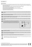
Technologies Inc.
Application Note
6 Bainard Street
London, Ontario N6P 1A8 CANADA
tel(519)652-9959 fax(519)652-1057
AN0802
WattsOn® Troubleshooting
Summary
The goal of this document is to present basic troubleshooting and commissioning steps for implementation of
WattsOn meters in various wiring systems.
The WattsOn® Universal Power Transducer is an
advanced meter capable of four-quadrant metering.
Because of this, correct wiring of voltage and
current inputs is critical to the measurement
accuracy of the system.
Danger
Line voltages up to 600 VAC are
present on the input terminals of
the device and throughout the
connected line circuits during
normal operation. These voltages
may cause severe injury or death.
The following tools are helpful in diagnosing
hardware installation issues:
Installation and servicing must be performed
only by qualified, properly trained personnel.
1. Digital Multimeter capable of mV AC and mA AC
measurements.
WattsOn Meters calibrated for use with 5A CTs have
special precautions that must be taken. NEVER
disconnect a 5A CT without shorting it first. These
CTs are capable of producing very high voltages and
arcing when not shorted, and as a result may cause
serious injury or death!
2. Clamp on Amp meter to verify current in line (if
possible).
Always ensure that 5A CTs are shorted via a
shorting block, or that power to the circuit
which the CT is installed on is off before
disconnecting from the meter.
5. Hookup wire for RS485 to WattsOn (twisted
pair, or "speaker" wire OK). Verify insulation
rating.
3. Computer running Windows (XP recommended)
4. USB-to-RS485 or RS232-to-RS485 converter
6. Elkor WattsOn Console Software
http://www.elkor.net/EWC_setup.exe
WattsOn meters with 5A inputs may be identified by
the part number (ie: WattsOn-1100-5A), or by the
yellow sticker on the face of the unit as below:
7. Basic tools (screwdrivers, etc).
5A CT
If unsure, contact the vendor to determine WattsOn
type.
11/11/2008, rev A
-1© Elkor Technologies Inc. 2006
AN0307
operation. Note: this feature can be disabled in
software, however it is ON by default from the
factory.
Troubleshooting Steps:
1. POWER SUPPLY: Before commencing other
troubleshooting steps, ensure that the WattsOn is
receiving a proper power supply. Power to the
WattsOn is provided by to the upper left (black) plug
in two-position connector.
Valid power supply
ranges are:
If the LED shows a Double-Flash followed by a short
pause and another Double-Flash, it may be
indicative of Firmware problems. Verify that the DIP
switch is set to an address other than "0". By
default, from the factory, the address is set to "1".
If the address DIP switch is 0, set it to "1", and reset
the power to the WattsOn (unplug the black power
plug for 5 seconds, and plug it back in).
20-26VDC or 18-24VAC / 100mA
Power may be provided via a small control
transformer capable of sourcing at least 100mA.
Preferred power is DC, and may be attained by
using a DIN rail mount switching power supply.
Elkor recommends the Lambda DSP10-24.
During normal measurement operation (ie: voltage
inputs above 25VAC), the DIAG LED should be OFF.
If the LED stays ON constantly, or turns on an off
erratically, it is an indication of reverse power
detection. This condition arises when the SUM of
the real power (watts) in all three phases is
negative. Please note however, in a three-phase
system (assuming balanced phases), if only one of
the phases is reversed, the NET will continue to be
positive.
The green Power LED should illuminate when the
WattsOn is receiving power, however note that the
LED will continue to be illuminated even during low
voltage conditions. That is, the LED is not an
indication of WattsOn "sanity" or "operation", but
rather that power is simply available.
3. TROUBLESHOOTING via SOFTWARE:
Note that voltages can sag when other equipment is
powered on, especially when using a small VA
control transformer. Therefore, it is best to verify
the input voltage using a DMM, on the terminals of
the black plug-in power connector to ensure that the
proper voltage is present.
Use of the WattsOn Console software for
troubleshooting and commissioning is highly
recommended. The software is capable of showing
all real time and accumulated parameters, as well as
allowing viewing and changing of configuration
parameters.
2. DIAG LED: The Red DIAG (diagnostic) LED has a
variety of functions. Depending on the state of the
LED, it can signify a number of conditions. The
table below summarizes the LED states and related
conditions:
LED State
OFF
Fast Flashing
Solid (ON)
Slow Flashing
Double-Flash,
pause,
Double-Flash
First, an RS485 connection must be available.
Typical solutions are RS232-to-RS485 or USB-toRS485 converters.
Elkor recommends the
converters by B&B Electronics. They are listed in
Appendix A. In any case, the converter should have
"Automatic Send Data Detection" to avoid issues
with data direction switching.
Condition
Normal operation, or insufficient
power supply voltage (see step 1)
Input Voltages below threshold
(typically ≤ 25VAC).
Reverse NET Power (kW) condition
Reverse Sequence (typically this is
disabled from the factory)
Firmware update mode check:
DIP Address switch must not be"0".
Potential firmware problem.
Make sure that the RS485 converter (whether USB
or Serial) is properly installed and that the
corresponding drivers are installed and initialized.
You will need to know the COM port of the installed
converter. The easiest way to accomplish this is to
load up device manager.
Click Start > Settings > Control Panel > System.
To test for WattsOn functionality or "sanity", it is
best to connect power and disconnect voltage
inputs. In this configuration, the RED LED should
flash rapidly.
This is an indication of proper
11/11/2008, rev A
Click on the "Hardware Tab" and click the "Device
Manager" button.
-2© Elkor Technologies Inc. 2006
AN0307
associated with the Serial port or USB where the
RS845 converter is connected.
In the list, there should be an entry called "Ports
(COM & LPT)". Click on the small + symbol next to
this text and observe the available COM ports. If
using a USB-to-RS485 converter, the port should
appear as you plug the device into the computer
(there may be a delay of up to 30 seconds), and
disappear once the device has been unplugged.
Take note of the COM port number associated with
the device. Figure 1 shows a screenshot of the
device manager.
By default, the WattsOn is configured for a Baud
Rate of 9600bps. Click "OK"
Click on Options > Device Address, and ensure that
the address is configured to the same setting as the
DIP switch on the WattsOn.
If the settings are correct, the text should show
COMM OK! Click Close.
Device appears as
it is plugged in.
At this point, real time data should appear on the
screen. If communications is still timing out (status
can be observed in the status bar across the bottom
of the screen), verify the address, COM setting, and
RS485 wiring polarity. If problems persist, please
refer to
Elkor AN0303
– Modbus
RTU
Troubleshooting, or contact the vendor.
Wiring of the RS485 converter to the WattsOn takes
place via the "+" / "-" / "G" terminals on the upper
green 8-position plug on the WattsOn. Many RS485
converters are labeled A/B. Typically A is wired to
"-" and B is wired to "+".
However, if
communications does not work, try to switch the
polarity. For short runs, it is not necessary to
connect the "GND" connection.
Install the WattsOn console software. Make sure
that the serial or USB converter is attached to the
computer, and start the software.
Click on the "Port" menu, and ensure that the
Drop-down box is selected to the COM port
11/11/2008, rev A
-3© Elkor Technologies Inc. 2006
AN0307
The WattsOn Console displays all real-time and
accumulated parameters which the WattsOn
measures. Using this tool, it is easy to check for
proper wiring and operation of the system. When
connected to an active system, the measurements
are shown on the screen and updated approximately
once per second.
The software provides the
capability to ensure that the wiring is correct and
that the measurements are valid.
There are
typically two common problems associated with CT
wiring:
Current Magnitude:
1. Current Magnitude: caused by improper CT
selection, CT ratio configuration, and physical CT
installation or damaged CT.
Using a mV meter set to AC measurements,
measure the mV reading on the input terminals of
each CT (between the I11 to I12, etc).
2. Power Direction / Low or negative Power Factor:
caused by reversed CT orientation on the wire,
reversed CT polarity (wiring to WattsOn) or
incorrect voltage/current phase matchup.
Non-5A WattsOns are configured to interpret a full
scale of approximately 333mV AC.
That is, a
measurement of ~333mV AC is proportional to the
full scale rating of the WattsOn (as indicated in the
part number and the front yellow sticker). For
example:
If possible, take a measurement from the line where
the WattsOn CT is installed using a clamp on style
amp meter.
In most typical three-phase
installations, the loads should be fairly balanced, and
the currents should be approximately equal in all
three phases.
If the currents are suspected, perform the following
diagnostics:
For P/N: WattsOn-1100-MS360-250A
Full scale is 250A
If mV AC measurement on current inputs is 100mV,
calculated measured current is approximately
100mV/333mV * 250A = 75A.
These steps may only be performed on non-5A
input meters. Please see the disclaimer at the
beginning of this application note.
11/11/2008, rev A
Keep in mind that this measurement is an
approximation. If this calculation yields the same
approximate result as the WattsOn measurement,
the problem is before the WattsOn. Ensure that the
CT wiring is not shorted and that the CT is not
damaged. In the case of split core CTs, ensure that
the two sides are properly mated together.
-4© Elkor Technologies Inc. 2006
AN0307
Power Direction / Low or negative Power Factor:
3) One at a time, reconnect the CTs to the
WattsOn terminal I11, I12. Make sure that
the CT wires are connected as a pair (ie: do
not mix the white from CT #1 with the black
from CT #2.
Verify that the power factor (PF a, PF b, PF c)
readings are within 0.800 to 1.000. Readings that
are very low or have a negative sign (a marginally
negative power factor ie: -0.950 to -1.000 may be
normal) should be given closer examination. Most
installations have a nominal power factor within
0.800 to 1.000 (positive). This indicates a lagging
power factor, and is normal (caused by motors,
fans, etc). An excessively low power factor may be
an indicator of incorrect voltage to current phase
matching.
4) Observe the Power Factor (PF a,b,c)
readings. Continue changing CTs until the
power factor reading is maximized (as close
to +0.900 to +1.000) as possible.
5) At this point observe the Power (P a,b,c)
readings to determine if they are positive or
negative.
It is imperative that the voltages measured by
the WattsOn on the V1, V2, V3 terminals,
correspond to the same phases as the CTs on
I11/I12, I21/I22 and I31/I32.
6) Repeat these steps for phase B and C.
The easiest way to verify this is to physically inspect
the wiring to ensure that the V1 voltage and I11/I12
CT are both connected to the same phase (similarity
for phases 2 and 3). A mismatch may be evidenced
by a poor power factor reading. The following table
shows the effects on power factor with mismatched
CTs.
Actual
Phase PF
1.000
0.950
0.900
0.800
Va with Ia
(correct)
1.000
0.950
0.900
0.800
Va with Ib
(incorrect)
-0.5
-0.745
-0.827
-0.919
Verify that the power (Pa, Pb, Pc) shows the correct
sign. For a typical installation, with correctly wired
and oriented CTs, the power should show POSITIVE
values. This indicates that power is being imported
(consumed). In a correctly installed system, a
negative reading indicates that power is being
exported (generated). In most load-only systems,
the cause for this is either reverse polarity of the CT
into the Ix1, Ix2 terminals or incorrect orientation of
the CT on the wire. The solution is to reverse the
CT on the wire, or reverse the input polarity.
However, before taking these steps it is prudent to
understand the origin of the problem as haphazard
re-wiring may make the situation worse.
Va with Ic
(incorrect)
-0.5
-0.204
-0.0725
+0.119
As the table shows, in some cases the power factor
may not be an ideal indicator of phase mismatch,
especially if the nominal power factor of the system
is much lower than unity. This table should be used
only as a guideline, since in rare circumstances the
power factor may truly be low or negative.
Always verify the correct wiring of the installation
with the wiring diagram provided by the vendor.
Appendix:
Elkor Recommended RS485 Adapters
If suspect power factor readings are observed, and
a physical trace of CT and voltage leads is not
possible or does not yield any results, the following
steps should be taken:
Manufacturer
FTDI
B&B Electronics
B&B Electronics
1) Mark all of the CT wire leads with their
currently connected terminals (I11, I12, etc).
This will aid in tracking progress.
Acroname
Part
Type
USB-RS485-WE-1800-BT
(available from
www.digikey.com)
485SD9TB
485USBTB-2W
485USBTB-4W
R305-USB-RS485
USB
2) Disconnect all of the CT wire leads from the
WattsOn terminals, and observe that the
measured current and power in each phase
drops to "0".
11/11/2008, rev A
-5© Elkor Technologies Inc. 2006
AN0307
RS232
USB
USB