1
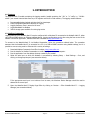
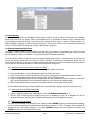
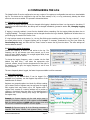
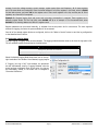
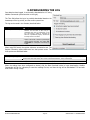
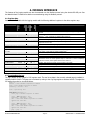
PRECISION ENERGY METER DATALOGGING (-L / -DL Option) USER MANUAL Installation Considerations Installation and maintenance of the WattsOn device must only be performed by qualified, competent personnel who have appropriate training and experience with electrical high voltage and current installations. The WattsOn device must be installed in accordance with all Local and National Electrical Safety Codes. WARNING Failure to observe the following may result in severe injury or death: During normal operation of this device, hazardous voltages are present on the input terminals of the device and throughout the connected power lines, including any potential transformers (PTs). With their primary circuit energized, current transformers (CTs) may generate high voltage when their secondary windings are open. Follow standard safety precautions while performing any installation or service work (i.e. remove line fuses, short CT secondaries, etc). This device is not intended for protection applications. Do not HIPOT and/or dielectric test any of the digital outputs. Refer to this manual for the maximum voltage level the meter can withstand. Do not exceed rated input signals as it may permanently damage the device. The power supply input should be connected via a rated 12-30 VAC/VDC power supply and properly isolated from the line voltage. Danger Line voltages up to 600 VRMS may be present on the input terminals of the device and throughout the connected line circuits during normal operation. These voltages may cause severe injury or death. Installation and servicing must be performed only by qualified, properly trained personnel. Limitation of Liability Elkor Technologies Inc. (“Elkor”) reserves the right to make changes to its products and/or their specifications without notice. Elkor strongly recommends obtaining the latest version of the device specifications to assure the most current information is available to the customer. Specifications and manual are available at http://www.elkor.net Elkor assumes no liability for applications assistance, customer’s system design, or infringement of patents or copyrights of third parties by/or arising from the use of Elkor’s devices. ELKOR TECHNOLOGIES INC. SHALL NOT BE LIABLE FOR CONSEQUENTIAL DAMAGES SUSTAINED IN CONNECTION WITH ELKOR PRODUCTS, EXCEPT TO THE EXTENT PROHIBITED BY APPLICABLE LAW. FURTHERMORE, ELKOR NEITHER ALLOWS NOR AUTHORIZES ANY OTHER PERSON TO ASSUME FOR IT ANY SUCH OBLIGATION OR LIABILITY. Although the information contained in this document is believed to be accurate, Elkor assumes no responsibility for any errors which may exist in this publication. ELKOR TECHNOLOGIES INC. - Page 1 - WattsOn-Mark II – LOGGING GUIDE TABLE OF CONTENTS Installation Considerations.....................................................................................................................................1 WARNING ............................................................................................................................................................1 Limitation of Liability .............................................................................................................................................1 Table of Contents.............................................................................................................................................. 2 1. Introduction.............................................................................................................................................. 3 1.1. Features........................................................................................................................................................3 1.2. Modbus Commander.......................................................................................................................................3 1.3. Flash Memory ................................................................................................................................................4 1.4. Battery-backed Real-time Clock .......................................................................................................................4 2. Configuring the Log .................................................................................................................................. 6 2.1. Changing Logging Settings..............................................................................................................................6 2.2. Selecting Logging Frequency ...........................................................................................................................6 2.3. Selecting Registers .........................................................................................................................................6 2.4. Selecting Logging Mode ..................................................................................................................................7 3. Downloading the Log ................................................................................................................................ 8 4. Modbus Interface...................................................................................................................................... 9 4.1. Register Map .................................................................................................................................................9 4.2. Downloading the Log......................................................................................................................................9 4.3. Log Format.................................................................................................................................................. 10 4.4. Example Configuration.................................................................................................................................. 10 ELKOR TECHNOLOGIES INC. - Page 2 - WattsOn-Mark II – LOGGING GUIDE 1. INTRODUCTION 1.1. Features The WattsOn-Mark II models containing the logging module (models containing the “–DL” or “–L” suffix, i.e., “W2-M1mA-DL”) can record historical data from any of its registers onto built-in Flash memory. The logging module features: Programmable battery-backed real-time clock for timestamps Freely configurable parameter selection for logging Logging frequency from 1 second to 18 hours Log downloadable via Modbus 2MB of storage space available for storing log entries 1.2. Modbus Commander Logging features of the WattsOn-Mark II may be configured with a Windows PC connected to the WattsOn-Mark II, either via a USB-to-RS485 cable or an Ethernet gateway device. Logging configuration can be done using the free version of the Modbus Commander application, available from Elkor’s website at http://www.elkor.net. To connect to the WattsOn-Mark II via Modbus Commander, follow the procedure outlined below. The procedure assumes that the WattsOn-Mark II is connected to a PC via a USB-to-RS485 converter using default settings, but it is possible to connect using serial or Ethernet with a variety of settings. 1. 2. 3. 4. Download Modbus Commander from Elkor’s website, http://www.elkor.net. Run the installer for Modbus Commander to install the program onto your computer. Run the application from the desktop shortcut created by the installer. Select the serial port on which the WattsOn is connected by selecting Setup → Serial Settings → Port, and clicking on the appropriate port (see screenshot below). If the appropriate serial port is not obvious from its name, the Windows Device Manager should be used to determine the correct port. 5. Open the WattsOn-Mark II Display Page Editor by clicking on Devices → Elkor WattsOn-Mark II → Logging Manager (see screenshot below). ELKOR TECHNOLOGIES INC. - Page 3 - WattsOn-Mark II – LOGGING GUIDE 1.3. Flash Memory The logging module contains two megabytes of flash memory used for storing log entries. Flash memory has inherently limited write endurance; the memory used in the WattsOn-Mark II is guaranteed to sustain 100,000 complete writes (from beginning to end) before failing. Each time the log is erased, the flash memory is reset to its starting position. If frequent logging is expected, it is best to allow the log to stay in “continuous” mode, thereby overwriting old entries, and writing in a circular fashion to incorporate a simple “wear-leveling” mechanism. 1.4. Battery-backed Real-time Clock The logging module contains a battery-backed real-time clock. The battery is rechargeable and should not need replacement. The clock must be set by the user before starting logging to obtain accurate timestamps. It can be set with the LCD display (if present), over Modbus, or using the free version of Modbus Commander. The clock contains a battery to allow the time to be retained despite power failures. The WattsOn-Mark II will retain the current time during a power failure of at least one month in duration. If the device is unpowered for longer than one month, check the device’s clock to see if it requires setting before starting a log. Note: the WattsOn-Mark II may require up to 48-hours to fully charge the battery if it has not been charged for a long time. 1.4.1. Setting the clock using the built-in display (if present) If the WattsOn-Mark II model includes a display, it can be used to quickly set the time. 1. 2. 3. 4. From the main screen, press the Back/Menu button to enter the main menu. Use the Down button to select Configuration with the cursor, and press the Forward/Select button to confirm. Press the Forward/Select button again to enter the Date and Time Settings screen. Press the Forward/Select button to enter the date editor. Use the Up and Down buttons to increase or decrease a digit, and use the Back/Menu and Forward/Select buttons to move left and right between digits. 5. When finished editing the date, press the Forward/Select button until the cursor leaves the field. See the WattsOn-Mark II Display Guide for details about using the display, editing numbers, and setting the time. 1.4.2. Setting the clock via Modbus Commander 1. Open the Logging Manager page, as described in section 1.2, Modbus Commander (p. 3). 2. Click the “Sync” button the use the program the current PC date/time into the unit. A date/time can also be manually entered into the Clock field, if a date/time different from the PC’s date/time is desired. 1.4.3. Setting the clock via Modbus The clock can be accessed as an unsigned 32-bit register at offset 0x4008 containing a standard UNIX timestamp; that is, it records the number of seconds that have elapsed since January 1st, 1970, at midnight. 32-bit registers are accessed as two 16-bit Modbus registers, in this case, 0x4008 containing the most significant two bytes, and 0x4009 containing the least significant two bytes. ELKOR TECHNOLOGIES INC. - Page 4 - WattsOn-Mark II – LOGGING GUIDE It is recommended that both registers be written with the same command, using Modbus Function 0x16 Write Multiple Registers; otherwise, the most significant register should be written first, followed by the least significant register, to avoid any anomalies. ELKOR TECHNOLOGIES INC. - Page 5 - WattsOn-Mark II – LOGGING GUIDE 2. CONFIGURING THE LOG The WattsOn-Mark II can be configured to save any number of its registers at configurable intervals into a downloadable log file. The device can be configured to log until the Flash memory is full, or to log continuously, deleting the oldest entries as new ones are added. The procedure is described below. 2.1. Changing Logging Settings The majority of logging settings can only be changed while logging is disabled and there is no log saved on the device. If logging has not been used before, the settings can be changed immediately (proceed to section 2.1, Changing Logging Settings). If logging is currently enabled, it must first be disabled before proceeding. Set the Logging Mode drop-down box to “Logging Disabled.” The logging frequency can be changed whenever the log is disabled, regardless of whether there is a pre-existing log file saved on the device or not. If a log has been saved on the device (i.e., the Log Size field reports something other than “No log on device”), it must be erased before the list of logged registers can be changed. If necessary, download the log first (see section 3, Downloading the Log), and then click the “Erase” button to remove the log from the device. The other settings can now be edited as desired. 2.2. Selecting Logging Frequency Choose the frequency at which to add entries to the log. The frequency can be set between once every second, up to once every 18 hours (64800 seconds). For a single register block, these times are accurate to ±1 second. To choose the logging frequency, enter a number into the field labeled “Log data every…” and select the appropriate units (seconds, minutes, hours) from the drop-down box to the right. In the example on the right, the logging frequency is set to once every 30 seconds. The more frequently data is logged, the faster the space available to will be consumed. 2.3. Selecting Registers Any register on the WattsOn-Mark II can be logged. For a complete list of registers, see the Register Map section of the WattsOn-Mark II manual. Registers are grouped together into blocks for efficient reading. Up to sixteen blocks of registers may be configured for logging. Each register block may contain up to 125 registers each. A register block consists of a starting address and a number of registers in that block. Note that many of the WattsOn-Mark II parameters are 32-bits, meaning they occupy two registers in the register map. Example 1: Suppose logging only the total active power is required. Total active power is a 32-bit register at offset 0x200. Enter the starting address as 0x200 and the register count as 2. The count is 2 because the register is a 32-bit register. Example 2: Suppose logging all of the following parameters is required: Total active, reactive, and apparent power, voltage ELKOR TECHNOLOGIES INC. - Page 6 - WattsOn-Mark II – LOGGING GUIDE average, line-to-line voltage average, current average, system power factor and frequency. All of these registers are in the same block and contiguous. Enter the lowest address of all of the registers in the block, which is 0x200 for total active power, and enter 16 for the register count. There are 8 registers in the list, and they are all 32-bit registers, so a count of 16 is required. Example 3: Suppose logging both real power and net energy consumption is required. These registers are in different register blocks. For the first block, enter 0x200 and 2, as in example 1. For the second block, enter 0x1100 for the starting address and 2 for the register count. Register addresses can be entered manually, or selected from the drop-down list for convenience. The more registers selected for logging, the faster the space available will be consumed. Once all of the desired register blocks are configured, click on the “Write to Device” button to send the log configuration to the WattsOn-Mark II device. 2.4. Selecting Logging Mode To begin logging, a logging mode must be selected. The logging mode determines what to do when the log space is full. The two available modes are described in the table below: Mode Overwrite Old Entries Until Full Description Logging continues indefinitely. Once the flash memory used to store the log is full, old entries are overwritten. Logging stops when flash memory is full. Select the desired Logging Mode drop-down box on the topright hand side of the window. Once selected, logging begins. If “Logging (unit log is full)” was selected, the drop-down box will automatically revert to “Logging Disabled” once the space has been completely filled. At that point, the log can be downloaded, erased, or the mode can be changed to “Overwrite Old Entries.” ELKOR TECHNOLOGIES INC. - Page 7 - WattsOn-Mark II – LOGGING GUIDE 3. DOWNLOADING THE LOG Once data has been logged, it can be easily downloaded to a PC using Modbus Commander (see screenshot on the right). The Time field allows the log to be partially downloaded based on the timestamps of the log entires, and the current system time. The log can be saved in two formats, described below: File Type Comma-Separated Values (.csv) Binary (.bin) Description Each value in the log entry is separated with a delimiter. The first value in each entry is a timestamp. Each entry is separated by a new line. This format is useful for importing the data into a spreadsheet program, and can also be easily read in a text editor. Each value is represented in binary one after another. This format is useful for processing by simple computer programs. See section 4.3, Log Format for a description of the binary log format. When using CSV format, the register values are converted to text. The Register Formatting options determine how that process occurs. The three options are described below: Register Formatting Option According to register type As decimal numbers As hexadecimal numbers Description The software will format each register value according to what kind of value the register represents. For example, both floating-point values and integer values will be converted appropriately. This is recommended. All registers will be converted based on their raw values, represented as integers in decimal format. All registers will be converted based on their raw values, represented as integers in hexadecimal format. When the settings have been configured as desired, click the Start Download button to begin downloading. Modbus Commander will ask for a directory to save the resulting file into, and then the log will be downloaded. This can take some time if the log is large. ELKOR TECHNOLOGIES INC. - Page 8 - WattsOn-Mark II – LOGGING GUIDE 4. MODBUS INTERFACE The features of the logging module can also be accessed over the Modbus protocol using the device’s RS-485 port. See the WattsOn-Mark II’s manual for details on communicating using the Modbus protocol. 4.1. Register Map WattsOn-Mark II models with the logging module add the following additional registers to the device register map. Offset Size Type R/W Default Name Module ID 0x4000 128 S R “IDLM” Clock 0x4008 32 U RW - Entry Count Entry Length Log Space Used 0x400A 0x400C 0x400D 32 16 32 U U U R R R - Logging Frequency Log Page Log Page Count Approximate Entries per Page Logging Mode Log Full Wipe Log Reserved … Reserved 1st Block Offset 1st Block Length 2nd Block Offset 2nd Block Length 16th Block Offset 16th Block Length 0x400E 0x4010 0x4011 0x4012 32 16 16 16 U U U U RW RW R R 0 - 0x4013 0x4014 0x4015 0x4016 16 16 16 - U B RW R 0 - - R - 0x401F 0x4020 0x4021 0x4022 0x4023 0x403E 0x403F 16 16 16 16 16 16 U U U U U U R RW RW RW RW RW RW 0 0 0 0 0 0 Description A string indicating the name of this module – the integrated display and logging module. The battery-backed real-time clock value, expressed as the number of seconds since January 1st, 1970, at midnight (a standard UNIX timestamp). The number of entries in the log. The number of registers occupied by a single entry in the log. A percentage indicating how much space in the log is used. A value of 10000 represents 100.00% full. How often to create a new log entry, expressed in seconds The “page” of the log currently available at register 0x4100. The number of “pages” in the log An approximate count of the number of entries per page. If 250 is not a multiple of the entry length, a page may also contain a partial entry. “0” for “Disabled,” “1” for “Log Continuously,” and “2” for “Log Until Full.” Indicates whether the log is completely full. When 0xA5A5 (42,405) is written to this register, the log is completely erased. Reserved for future use. These registers output “0” when read. To ensure compatibility with future versions, these registers should not be written to. Register offset of the first register in the first block to be logged. Length of the first block to be logged. Register offset of the first register in the second block to be logged. Length of the second block to be logged. Register offset of the first register in the last block to be logged. Length of the last block to be logged. 4.2. Downloading the Log The log is broken up into “pages” of 250 registers each. The raw binary data in the currently selected page is available in registers 0x4100 to 41FA. The page can be selected by writing to the Log Page register at address 0x4010. The algorithm for reading the entire log is outlined below: page ← 0 entries ← read 2 Modbus registers at 0x400A size ← read 1 Modbus register at 0x400C remaining ← entries × size file ← open binary file loop while remaining > 0 write page to Modbus register at 0x4010 count = min(remaining, 125) remaining = remaining - count data = read count Modbus registers at 0x4100 append file with data count = min(remaining, 125) remaining = remaining - count data = read count Modbus registers at 0x417D append file with data page = page + 1 ELKOR TECHNOLOGIES INC. - Page 9 - WattsOn-Mark II – LOGGING GUIDE 4.3. Log Format The log is composed of a sequence of entries, with the most recent entry first. Each entry is a series of bytes. The first four bytes represents the timestamp of the entry, and the remaining bytes represent each register that was chosen to be logged, in order. Each register requires at least 2 bytes, though many of the registers available in the WattsOn-Mark II require 4 bytes (such as all of the real-time and accumulated electrical parameters). Show below is an example in which 4 registers have been logged. First Entry (most recent) Timestamp 0 Reg 1 2 4 Reg 2 6 Second Entry Reg 3 8 Reg 4 10 Timestamp 12 14 Reg 1 16 Reg 2 18 Reg 3 20 Reg 4 22 … 24 4.4. Example Configuration For example, suppose the device is configured to log two parameters, the Net Total Energy (register 0x1000) and the Total Active Power (register 0x100), every 1 minute. To do this, the following registers are set to the values indicated in the table below. For this example, the 32-bit integer versions of the registers are used. Register Logging Frequency 1st Block Offset 1st Block Length 2nd Block Offset Offset 0x400E 0x4020 0x4021 0x4022 Value 60 0x1000 2 0x100 2nd Block Offset 0x4023 2 Notes Represented in seconds. Address of the first (and only) register in the block, Net Total Energy. Length of the block. Because Net Total Energy is 32 bits long, 2 registers are required. Address of the first (and only) register in the block, Total Active Power. This register is not continuous with the previous register, 0x1000, so two separate blocks are required. Length of the block. Because Net Total Energy is 32 bits long, 2 registers are required. Suppose that logging is started at January 1st, 2015, at midnight. At this time, the total active power is a constant 12 kW, and no energy been accumulated previously. The log is started by writing a “1” to the Logging Mode register at address 0x4013. After one minute has passed and the log is downloaded, it will be in the format illustrated below. For each parameter, its name is given, followed by the decimal value of the parameter on the next line, followed by the value of each individual byte (shown in hexadecimal) on the last line. First Entry (most recent) Timestamp 54 0 Net Total Energy* 1420070460 A4 8E 3C 2 Total Active Power** 120000 00 01 D4 C0 2 00 4 00 00 6 Second Entry 02 8 10 Timestamp 54 12 Net Total Energy 1420070400 A4 8E 00 14 Total Active Power 0 00 16 00 00 18 00 00 20 120000 01 D4 22 C0 24 * In this example, Net Total Energy assumes a default energy divider setting of 100, thereby the integer energy registers have a resolution of 100Wh. When Net Total Energy shows “2” in this case, it represents an accumulation of 200 Wh (12 kW after 1 minute) ** Total Active Power has a resolution of 0.1W, therefore when Total Active Power shows 120,000, it represents a value of 12,000.0 W ELKOR TECHNOLOGIES INC. - Page 10 - WattsOn-Mark II – LOGGING GUIDE Elkor Technologies Inc. 6 Bainard Street London, Ontario N6P 1A8 Tel: 519-652-9959 Fax: 519-652-1057 www.elkor.net © 2015, Elkor Technologies Inc.