1
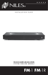
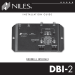
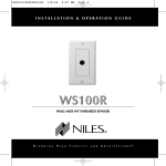
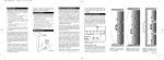
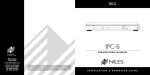
M O D E L
MS-1
MS-1
MICROSENSOR™ MINIATURE INFRARED SENSOR
I N S TA L L AT I O N & O P E R AT I O N G U I D E
M
I N I A T U R E
I
N F R A R E D
S
E N S O R
MS-1
MicroSensor TM
Miniature
IR Sensor
TABLE OF CONTENTS
Introduction
Introduction
1
The MS-1 is a miniature IR sensor designed for use with the
Niles Infrared Repeating systems.
Features and
Benefits
2
Installation
Considerations 3
Installation
9
Operation
11
Troubleshooting
12
Specifications 14
Installed in a remote room location, the MS-1 receives the IR
commands transmitted from your existing hand-held
remotes in that room. The commands are carried via a small
2-conductor shielded cable to your A/V equipment in another room, and instantly "repeated".
The MS-1 is compatible with all current Niles infrared
systems. It may be used along with, or as an alternative to,
the Niles IRR4D+, IRR4S+, SCW-UIR, MS-2, TIR1+ and MS360
IR sensors.
The MS-1 is just one part of the three building blocks necessary to complete a Niles IR repeating system:
●
Main System Unit —IntelliControl™, RVL-6, IRP2+, IRP6+,
IRZ6+.
●
IR Sensors — Models IRR4D+, IRR4S+, SCW-UIR,
TIR1+, MS-1, MS-2 and CMS-3.
●
IR Flashers —Models IRC-1 and IRC-2.
An expansion unit, Model XRP6+, is available for IR repeater
systems requiring control in more than six rooms.
M
I N I A T U R E
I
N F R A R E D
S
E N S O R
Features and Benefits
The MS-1 offers a number of improvements over other
miniature IR sensors.
●
Small size of only 1/2" diameter by 2-5/16" long — fits
almost anywhere.
●
Universal system — compatible with virtually all brands of
A/V equipment and remote controls.
●
Excellent IR receiving range — you get 18 to 30 feet of
remote control range (depending upon the strength of
your handheld remote).
●
100% factory tested for pickup range and angle.
●
Green "flash-back" L.E.D. visually confirms remote control
operation.
●
Simple 3-wire hookup—10 feet of IR cable included.
●
Printed circuit board design uses surface mount technology
(SMT), assuring high reliability.
●
Ideal for both home and commercial installations.
●
Bezel colors: Each MS-1 includes a black and white bezel.
●
Two year parts and labor warranty.
●
Proudly made in the USA.
IMPORTANT
Refer installation
to a professional
custom installer if
you are unfamiliar
with any of the
following
procedures.
2
M
I N I A T U R E
I
N F R A R E D
S
E N S O R
Installation Considerations
Type of Cable
TOOLS
REQUIRED
• 1/8" Standard
Slotted
Screwdriver
• Adjustable
wrench or pliers
• Wire Stripper
The MS-1 connects to the Niles Infrared Systems with an
individual home run of 2-conductor shielded cable.
Recommended cables are Niles data grade IR cable, West
Penn D291, Belden 8761, Carol C2516 or equivalent, made
of two 22 gauge (or larger) conductors surrounded by a foil
shield and a bare drain (ground) wire.
DO NOT USE UNSHIELDED CABLE WITH THE MS-1.
MS-1 Mounting Location
The MS-1 is ideal for use in applications when tabletop, ceiling, or wall-mounting is undesirable. Its small size and unobtrusive appearance makes it ideal for installation in obscure,
hidden locations, in cabinet facings, or in the “sensor knockout built into Niles in-wall loudspeakers. Installing the MS-1
close to the primary location of the user will ensure best performance.
The MS-1 is designed to flush-mount almost anywhere.
Convenient mounting locations for the MS-1 are:
●
●
●
3
In a cabinet door
In a wall, or wall-plate
Behind a speaker grille*
* Some types of speaker grilles will reduce the IR pickup range of the
MS-1. If unsure, test the pickup range before permanently installing
the MS-1 behind the speaker grille.
M
I N I A T U R E
I
N F R A R E D
S
E N S O R
Receiving Range and Pickup Angle
The receiving range of the MS-1 will vary according to the IR
output strength of the remote control being used. Remote
strength varies among brands depending on the number
and size of batteries used, and how many IR emitters the
remote has. For example, remotes that operate on two small
AAA batteries and have only one IR emitter are generally not
as strong as remotes that use the larger AA size batteries and
have two emitters. Tests with various manufacturers' remote
controls have shown that the operating range can vary from
a minimum of 18 feet to a maximum of about 30 feet.
Infrared signals travel essentially line-of-sight. They will not
pass through or around solid objects. Do not rely on an IR
signal being able to "bounce" off a wall or object to the MS-1.
o
The IR pickup angle of the MS-1 is 60 off-axis (horizontal
and vertical) at 18 feet. For more information see (Figure 3)
MS-1 Operating Range on Page 11.
Avoiding Optical Interference
As with any type of IR sensor, avoid locating the MS-1 where
it will be exposed to direct sunlight. The sun emits an enormous amount of IR energy, many times stronger than that of
a hand-held remote. Keep in mind that the less sunlight the
MS-1 receives, the better the range of the remotes.
DO NOT mount the MS-1 outdoors. During daylight hours,
you will experience poor range and/or interference.
4
M
I N I A T U R E
I
N F R A R E D
S
E N S O R
Avoiding Electrical Interference
Avoid locating the MS-1 near any potential sources of electrical or optical noise, such as light dimmers, florescent lighting
fixtures, low-voltage lights, and neon lights.
If you are installing the MS-1 near a television, keep it at least
6" away from the top, bottom or sides of the TV to avoid
interference. Avoid running the MS-1's cable on the top of
the TV, or near the back cabinet of the TV. This will help
reduce the possibility of interference.
"TECH TIP"
Do not install the
MS-1 next to a light
dimmer, or where it
will be exposed to
direct sunlight.
5
DO NOT INSTALL THE MS-1 INTO ELECTRICAL BOXES WITH
110 VOLT DEVICES.
Some states or municipalities allow devices such as the MS-1
to be installed into the same electrical box as 110 volt
devices, provided a "low-voltage partition" is used between
the devices. We do not recommend this. The cable connected to the MS-1 can act as an "antenna" for electrical noise.
Locating the MS-1 cable too close to a light dimmer or
switch may interfere with the MS-1. If you must locate the
MS-1 near electrical devices, install it in a separate metal electrical box, ground the box to the electrical system ground,
and route the MS-1 cable several feet away from all electrical
wiring.
M
I N I A T U R E
I
N F R A R E D
S
E N S O R
Avoiding Optical Feedback
If installing the MS-1 in the same room as an IR flasher, it is
possible for the flasher's IR output to be picked-up by the
MS-1. This effect, known as an optical feedback loop, can
cause erratic operation. Optical feedback is similar to acoustical feedback: the howling or whistling sound heard in a P.A.
system when the microphone is too close to the speaker. To
avoid optical feedback:
1. Lower the output power of the flasher(s) using the variable
flasher level control(s) on the Niles Main System Units.
2. Re-position the flasher(s) and/or the sensor.
3. Use Niles IRC-2 flashers and cover them with the supplied
IR blockers.
Changing the Color of the MS-1
The bezel surrounding the lens on the MS-1 is removable,
allowing fast and easy color changes as needed. A black and
white bezel are included with your MS-1. If you desire, you
may paint the MS-1 bezel yourself — to blend it seamlessly
into your decor.
If you need to change the color of the MS-1:
1. Hold the MS-1 as shown in (Figure 1) on next page.
Unscrew the bezel by turning it counter-clockwise. Note
that the MS-1's lens is held in place by the bezel — be
careful not to lose it.
6
M
I N I A T U R E
I
N F R A R E D
S
E N S O R
Figure 1
Removing the Bezel
2. Hold the MS-1 so that the front of it is facing you, making sure that the lens is in place. Screw the new bezel onto
the MS-1 by turning it clockwise.
7
M
I N I A T U R E
I
N F R A R E D
S
E N S O R
a
b
c
d
e
f
(a) Hex Nut (supplied)
(b) Washer (supplied)
(c) Mounting Surface
(d) IR Cable (10 feet supplied)
(e) MS-1 Miniature IR Sensor (supplied)
(f) MS-1 Lens Bezel (supplied)
8
M
I N I A T U R E
I
N F R A R E D
S
E N S O R
Installation
If you are installing the MS-1 into an existing wall, take time
to consider any possible obstructions which may be hidden
inside the wall, such as wood and metal studs; electrical, telephone or other types of wiring; plumbing; conduit; old wall
safes; etc.
1. Determine a mounting location for the MS-1. Select a
location where you will have access to the rear of the MS-1
after it is installed. This will allow you to securely tighten the
MS-1 to the mounting surface using the supplied hardware.
2. Drill a 1/2" hole where the MS-1 will be mounted.
3. Run the MS-1's IR cable. Label the cable for future reference. The MS-1 is supplied with 10' of pre-stripped IR cable.
The IR cable may be shortened or lengthened as needed. If
you want to make the MS-1's cable shorter, use a pair of wire
cutters to cut the cable to the desired length. The IR cable
may be lengthened by splicing it to a recommended IR cable
(See Installation Considerations — Type of Cable). You may
splice the MS-1 cable to another cable by soldering or crimping the connections.
9
4. Connect the MS-1 cable to the Main System Unit. Strip
1/4" of insulation from the end of each wire. Tightly twist the
end of each wire until there are no frayed ends. Insert the end
of each wire into the appropriate hole on the Main System
Unit's connector block; secure the wiring to the connector by
tightening the small connector screws. Double-check all connections. See (Figure 2).
M
I N I A T U R E
I
N F R A R E D
S
E N S O R
IRP2+
MODEL I R P 2 +
+
12
V
G
N
D
D
A
T
A
+
12
V
G
N
D
D
A
T
A
DATA
OUT
FLASHERS
FULL
POWER
STATUS
MS-1
IR
FLASHER
LEVEL
SENSOR INPUT
+
VAR
+
G
N
D
D
A
T
A
+12V DC
Room 1
Receiver
+
12
V
G
N
D
Figure 2
Wiring Diagram
(Installed in an
IRP2+ System)
D
A
T
A
SENSOR IN
Bare
Red
Black
To unswitched
AC Outlet
MS-1 Wiring Configuration
PIN 1 =
PIN 2 =
PIN 3 =
Red
Bare
Black
(+12V DC)
(GND)*
(DATA)
* You must use the bare
drain wire for the
ground connection.
NOTE: The color code shown above is for West Penn D291
IR cable. Actual color code of recommended cables may vary.
5. Secure the MS-1 by tightening the hex nut. DO NOT
OVER-TIGHTEN.
10
M
I
I N I A T U R E
N F R A R E D
S
E N S O R
Operation
This manual contains instructions for the MS-1 only. For specific information on the adjustment and operation of your
Niles Infrared system, please refer to the instruction manual
included with your Niles Main System Unit.
Operation of the MS-1 is straightforward. Simply aim your
hand-held remote at the MS-1. Your IR command is instantly
repeated to your A/V equipment. A green "flash-back" LED
on the MS-1 visually confirms the presence of an IR signal.
MS-1
60°
Figure 3
MS-1 Operating
Range
60°
50°
50°
18'
*All Angles
Referenced
to Center Axis.
40°
40°
22'
30°
26'
30'
11
30°
M
I N I A T U R E
I
N F R A R E D
S
E N S O R
Troubleshooting
The "flash-back" LED on the front of the MS-1 is a useful
troubleshooting aid.
The LED should light only when a remote command is being
received.
If the MS-1 does not work, and the LED does not light at all:
1. Test the remote control(s) by operating the A/V equipment directly. Replace the batteries if needed.
2. Double check the cable connections on all MS-1's and on
the Main System Unit. Look for open, shorted or reversed
wires.
If the MS-1 does not work, and the LED remains solidly lit:
1. Double check the cable connections on all MS-1's and on
the Main System Unit. Look for shorted or reversed wires.
2. Test for interference from the following sources:
●
Sunlight in the area of the MS-1
●
Fluorescent, neon or halogen lights in the room
●
Light dimmers, beginning with those closest to the MS-1
Observe the MS-1’s LED while performing all the tests. It is
possible to have interference from more than one source.
12
M
I N I A T U R E
I
N F R A R E D
S
E N S O R
There are many methods for reducing interference. Which
solution is best for you depends on your situation. Contact
Niles Technical Support at 1-800-289-4434 if you require
further assistance.
If the LED on the MS-1 "flickers" dimly, and the MS-1
functions normally, there is no cause for concern.
13
M
I N I A T U R E
I
N F R A R E D
S
E N S O R
Specifications
IR System
Compatible with virtually all brands of remotes using carrier
frequencies between 18 and 100 kHz
IR Receiving Range
Varies depending on remote strength; 18-30 feet typical
IR Receiving Angle
o
60 off-axis (horizontal and vertical) at 18 feet
Mounting
Thru-hole, fits into a 1/2" diameter hole; requires a
minimum of 2-5/16" mounting depth
Wiring Requirements
Individual home-runs of 2-conductor shielded cable, Niles IR
Cable, West Penn D291 or equivalent
Unit Dimensions
Front Bezel: 3/4" diameter x 1/4" high
Overall Unit: 1/2" diameter x 2-1/2" long
14
Niles Audio
Corporation
www.nilesaudio.com
12331 S.W. 130 Street
Miami, Florida, 33186
Tel: (305) 238-4373
Fax: (305) 238-0185
© 1999 Niles Audio Corporation. All rights reserved. Because Niles believes in constantly improving its
products, Niles reserves the right to change product specifications without notice. Niles and the Niles
logo are registered trademarks of Niles Audio Corporation. MicroSensor is a trademark of Niles Audio
Corporation. Printed in USA 1/99 DS00109B